

Page 1

HVAC pressure
applications with
the Fluke 922
For contractors troubleshooting pressure,
a lot depends on system peculiarities. Are
the installation instructions with the equipment? Is the start-up performance report
with them? Is the TAB (test and balance)
report available? Do you understand the
Application Note
control system? More often than not, it
seems, you can only answer yes to the
last question. You rely on your experience,
knowledge, and tools to check the fundamentals. And for that much, at least, Fluke
can help.
Pressure measurement
Pressure is measured in several different scales. Pounds
per square inch (psi), inches of
water column (in. wc), inches
of mercury column (in. hg), and
millionths of a meter of mercury
column (microns) are the most
typical in HVAC work.
Bourdon gauges are the traditional choice for higher pressure
readings in psi. Finer precision
measurements use mercury column scales. And for the most
precise measurements—and most
low pressure measurements in
HVAC—inches water column is
the standard.
The following chart compares
these common pressure scales
and their precision.
Using the Fluke 922 low pressure differential meter in a duct traverse.
F r o m t h e F l u k e D i g i t a l L i b r a r y @ w w w . f l u k e . c o m / l i b r a r y
Atmospheric Pressure 1 psi 1” hg 1” wc
14.696 psia 1 psi 0.019 psi 0.0361 psi
29.921 “ hg 2.036” hg 1” hg 0.0736” hg
406.8” wc 27.68” wc 13.595” wc 1” wc
Of the many different low
pressure measuring instruments
used over the years, electronic
manometers/micromanometers
(very low pressure gauges)
now offer durability, precision,
accuracy, and the significant
time saving convenience of fully
automatic calculations as well as
minimum-maximum-average and
memory functions.
Page 2
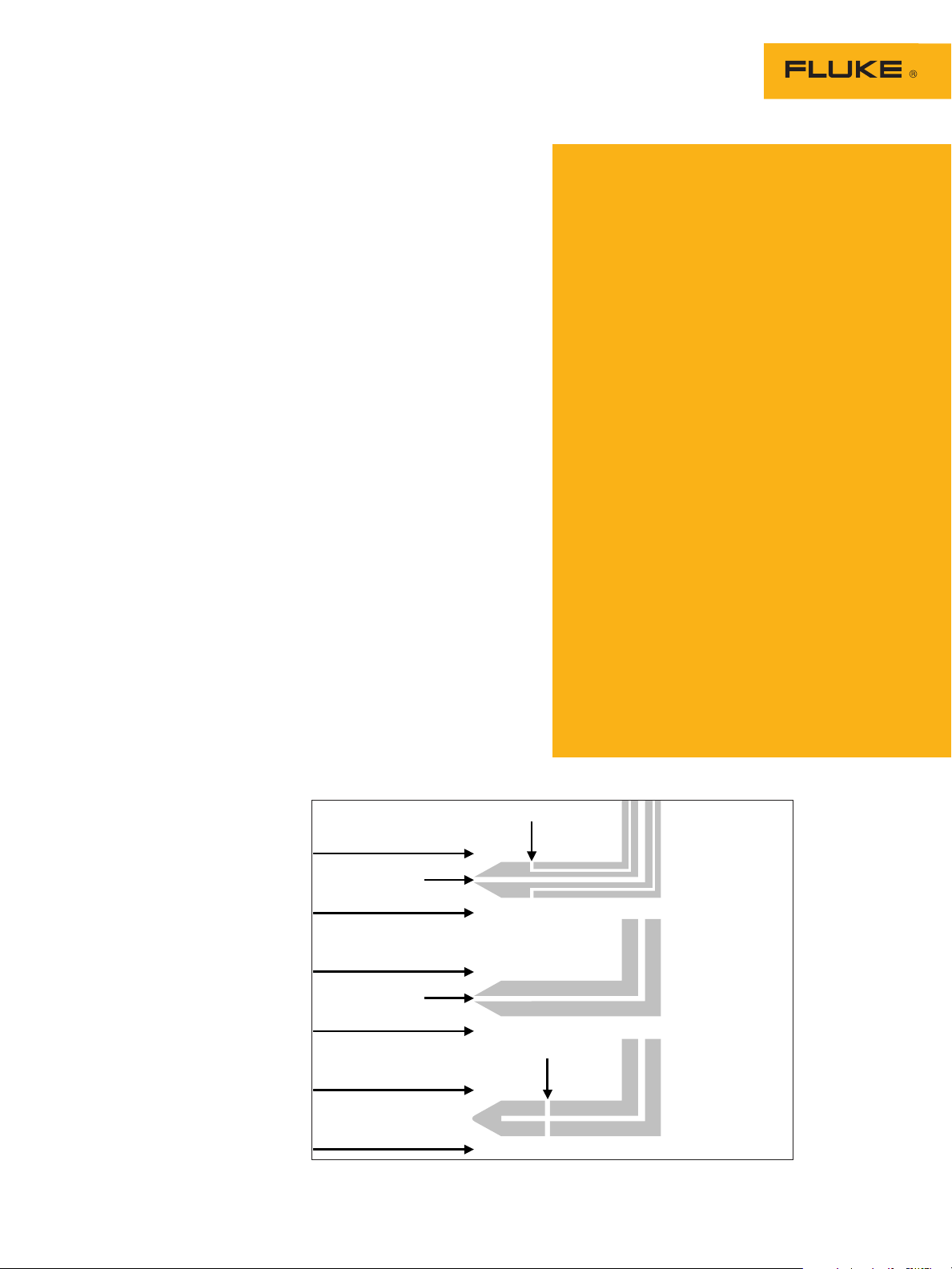
How pressure sensing
Total Pressure
Airflow
Airflow
Pitot-Static Tube
Pitot Tube
Static Pressure
Static Pressure
Total Pressure
Airflow
Airflow
Airflow
Airflow
Static Tip
works
The Fluke 922 is a low pressure differential meter used in
traditional manometer or micromanometer applications. It has
a range of +/-16” wc, resolution
of 0.001” wc, and over-pressure protection of 10 psi at each
high and low pressure port.
With a single tube connected to
its high or low port, the meter
will display positive or negative
pressure relative to the ambient pressure at the meter’s open
port. For a pressure differential
at two remote points, use tubing
to connect the higher pressure
sensing point to the “+” port and
the lower pressure sensing point
to the “-” port.
The meter uses a variety of
sensing probes and fittings to
access the type and location of
pressure measurement points.
These can be as simple as a
straight metal tube for checking draft, a “Tee” for tapping
into pressure sensing tubing
connected to a pressure switch,
a Pitot tube for sensing total
pressure, a Pitot-Static tube for
sensing both total and/or static
pressure, or a static pressure tip.
Pressure applications
Draft pressures: Draft pressures
are negative relative to ambient
pressures at the burner. Measuring and controlling draft is a critical step in combustion tests and
influences net thermal efficiency
of the appliance. Draft is created
by vertical vents or powered
sidewall vent systems connected
to fossil fuel equipment. Like too
much air, excessive draft through
a heat exchanger increases the
velocity of the combustion products containing heat, thereby
reducing the contact time in the
heat exchanger. Follow guidelines from the manufacturer or
standards authority.
Over-fire draft: Power burners typically have specifications
related to over-fire draft, which
relates to the velocity of combustion products through the
heat exchanger. This over-fire
draft typically is slightly negative (-0.01” wc to -0.02” wc)
but, depending on burner type
and application, may be slightly
positive (0.01” wc to 0.02” wc).
Follow guidelines from the manufacturer or standards authority.
Draft inducer pressure:
Category I fan-assisted gas appliances utilize a combustion air
inducer to create draft through
the appliance and deliver the
combustion products to a negative pressure vent. A pressure
switch is normally connected
to the inlet side of the inducer
to ensure a minimum draft has
been established before allowing
an ignition sequence to begin
or continue. For testing, a “Tee”
taps into the pressure sensing
tubing, to monitor the draft
created by the inducer. This is an
important value to benchmark at
appliance installation. While the
pressure switch ratings list cut-in
and cut-out (or differential)
pressures, without a benchmark
you can’t evaluate changes
within the appliance or vent over
time. Follow guidelines from the
manufacturer.
Pressure effects and
measurements
Pressure is an integral part of HVAC
equipment design, system design, function, application, control and diagnostics.
Pressure determines
• cleanliness of airside devices (pressure
drop across filters, evaporators, etc.)
• boiler steam temperature
• the saturation temperature of a fluid
(boiling temperature of a liquid, the condensing temperature of a vapor)
• the direction of fluid flow (fluids flow
from higher to lower pressures)
• fluid volume flow rate (pressure drop
across an orifice)
• whether or not a control or safety switch
will make or break (high/low pressure
switches, draft proving switches)
• the availability of a fluid to perform work
(oxygen/nitrogen tank pressures, gas
supply pressures, duct static pressures)
Pressure also
• senses zone device positions, modu
lates VFD drives, bypass dampers and
valves
• affects solubility of air in water
• contributes to flue gas velocity
(stack draft)
-
2 Fluke Corporation HVAC pressure applications with the Fluke 922
Options for sensing probes and fittings when accessing pressure measurement points.
Page 3

Combustion air blower pres-
sure differential: Category IV
direct vent gas appliances typically use a combustion air blower
to ensure airflow through the
vent system and appliance before
ignition. In most cases, a pressure differential switch monitors
pressure differential across an
orifice. Greater pressure differential indicates more airflow, lower
differential indicates less airflow.
In this case, two tees are needed
to tap into both the high and
low pressure sensing tubes connected to the pressure differential switch. This is an important
value to benchmark during appliance installation. Pressure differential depends on the length of
connected vent and the application. If this value is benchmarked
when installed, degradation
to differential created by heat
exchanger, condensate or vent
problems is more likely to be
detected before a failure occurs.
If not benchmarked, there’s no
way to evaluate degradation.
Follow guidelines from the
manufacturer.
Fan effects on combustion
pressures: When checking stack
draft, over-fire draft or combustion air inducer/blower pressure
differential, an abrupt change
in pressure when the blower
starts may indicate a compromise
between the flue passages and
the air passages. Fan pressure
can easily be 15 times or more
greater than flue passage pressure (-0.03” wc draft vs 0.5”
ESP), so abruptly changing draft
pressures commonly indicate
heat exchanger leaks. Gradual
changes in draft pressures most
likely mean combustion air supply problems or vent problems,
especially when accompanied
by rising CO and CO2, and falling O2 levels in the combustion
products. This can be caused
by insufficient make-up air or
return leaks, especially in spaces
that are considered confined
(less than 50 cu ft per 1,000
Btu input) or tight construction.
Use the Fluke 922 to compare
equipment room pressure to
outside pressure before and dur-
the equipment room can often
compensate for this engineering
design deficiency.
VAV (Variable Air Volume)
control: Pressure sensors are
often used to control VFD (variable frequency drive motor) RPM.
For instance, a supply duct pressure sensor can modulate the
RPM of a VFD, based on pressure
changes caused by a combination of open and closed zone
dampers. Exhaust VFD blowers
may modulate RPM based on
pressure differential between the
occupied space and outdoors. In
each of these cases, the VFD varies RPM to maintain a relatively
consistent pressure or pressure
differential. The Fluke 922 can
be used to monitor or check the
calibration of these sensors.
CAVB (Constant Air Volume
with Bypass) damper control:
Equipment with a constant RPM
blower may need to simulate
VAV in the supply duct, when
zoning is used. The control is
similar to a true VAV system. A
pressure sensor monitors supply
and modulates a bypass damper.
The damper relieves pressure
from the supply to the return,
maintaining a consistent supply
static pressure. The Fluke 922
can monitor or check the calibration of these sensors.
Pressure differential defrost
control: Some enthalpy wheels
use a differential pressure sensor to determine if a defrost cycle
is needed during cold weather.
A pressure differential increase
(indicating a frost build up) will
cycle the outdoor air intake
blower off , so it can use the
indoor air to defrost the wheel.
The Fluke 922 can be used to
monitor pressure differential,
check the calibration of the sensor, or test defrost operation.
Some air-to-air heat pumps use
a pressure switch to monitor
pressure drop across the outdoor
coil to determine if frost build-up
warrants a defrost cycle. In that
circumstance, the Fluke 922 can
be used to monitor defrost pressure differential, since restricted
airflow may indicate a frosted
coil.
ing equipment operation. Simply
adding a small supply register in
3 Fluke Corporation HVAC pressure applications with the Fluke 922
Airside devices: Pressure
drop across airside devices is
published by manufacturers and
is necessary for design considerations, including selecting
equipment for satisfactory blower
performance and for duct design
considerations. Once installed,
these same performance tables
are useful in estimating airflow
and determining end of life for
filters. Evaporators, for instance,
will have pressure drops with
associated cfm’s for a clean dry
coil and for a clean wet coil.
High performance filters will
have pressure drops with associated cfm’s for a clean filter, and
pressure drops with associated
cfm’s for that same filter when it
has reached the end of its life.
The Fluke 922 can be used
with a choice of pressure sensing devices to check pressure
drop across an airside device.
If the approach to and from the
device is straight, a Pitot tube
can be placed on each side of
the device and the difference in
total pressure readings will result
in pressure drop. The tube connected to the upstream side Pitot
tube is connected to the 922
“+” port, the tube connected to
the downstream side Pitot tube
is connected to the “-” port, the
pressure reading displayed will
be the device pressure drop. If
the approach is not straight to
the device, then use the static
sensing side of the two PitotStatic tubes, or use two static
pickups connected to the meter
in the same manner.
Confirming pressure drop across the air filter bank.
Page 4

TSP and ESP: Total Static
Pressure (TSP) and External Static
Pressure (ESP) are used in conjunction with the manufacturer’s
blower performance tables to
ensure that the blower performance is sufficient to overcome
airside device pressure drops
and the pressure drop associated
with duct friction and fittings
losses. Manufacturer’s blower
performance tables will specify
whether the tables are based
on TSP or ESP. Once installed,
the TSP or ESP is measured to
select the appropriate fan RPM
that will deliver the desired cfm.
It’s important to remember that
manufacturer’s blower curves
are developed by AMCA test
procedures that do not exhibit
any system effect. Due to equipment installation space and
configuration limitations, blower
performance is rarely the same
as system performance (“as-built”
rarely performs exactly “asdesigned”). Initial blower set up
is by TSP or ESP. Duct traverses
that measure actual airflow are
required for final blower set up.
TSP is normally provided for
commercial and industrial unitary
equipment. TSP includes internal
and external dynamic pressure
losses the equipment fan must
overcome. A static pickup is used
on the inlet side of the fan to
measure static pressure and the
connecting tube is connected to
the “-” port on the Fluke 922.
A static pickup is placed on the
discharge side of the blower and
the connecting tube is connected
to the “+” port on the Fluke 922.
The displayed pressure is the
TSP.
ESP is normally provided for
residential unitary equipment.
ESP is provided for equipment
that does not have optional
components that can be added
within the cabinet or when drilling holes to take TSP may violate
equipment agency certifications.
The blower tables are based on
dynamic pressure losses external
to the equipment, measured at
the return opening and at the
supply opening of the unitary
equipment. Check the blower
table instructions to determine
whether or not the filter should
be in place when measuring ESP.
Place a static pickup in the return
duct at the equipment return
opening. Connect this tube to the
“-” port of the Fluke 922. Place
a static pickup in the supply
duct at the equipment discharge
opening before any external
devices such as an external
evaporator, if so equipped. Connect this tube to the “+” port on
the Fluke 922. The displayed
reading will be the ESP.
FSP (Psf) is Fan Static Pressure
and is used to independently
rate a fan’s ability to overcome
all system dynamic pressure
losses. A Pitot tube is used on the
inlet side of the fan to measure
total pressure and the connecting
tube is connected to the “-” port
on the Fluke 922. A static pickup
is placed on the discharge side
of the blower and the connecting
tube is connected to the “+” port
on the Fluke 922. The displayed
pressure is the FSP.
Conclusion
Pressure is an often-misunderstood aspect of HVAC diagnostics. Everyone has refrigerant
pressure gauges, but to understand why “the pressures are
wrong,” you need to think about
fluid flow and heat transfer
too, instead of just adding gas
to force the pressures up. And,
while everyone probably has a
pressure gauge, it’s not always
the right kind for accurately
reading low pressure systems.
Now, with electronic meters like
the Fluke 922, you not only get
an accurate read, you can check
the actual pressure differential
instead of replacing pressure differential switches by default.
Using the Min/Max/Avg feature
The MIN-MAX feature on
the Fluke 922, in addition
to capturing minimum and
maximum readings, will
record and average readings when a fluctuating
pressure, velocity, or airflow
is encountered.
Once you’ve captured
pressure, velocity, and/or
airflow readings and stored
them in memory, they can
be recalled per selected
mode for review and
deleted individually, or as a
group.
4 Fluke Corporation HVAC pressure applications with the Fluke 922
Applications for
Min/Max/Avg include
checking:
• static pressure variations
as zone dampers open
and close
• CAVB bypass sizing and
damper operation
The average function is
most useful when air turbulence causes minor fluctuations in readings. The
average feature smoothes
out the slight variations,
making pressure evaluations more accurate.
Fluke. Keeping your world
up and running.
Fluke Corporation
PO Box 9090, Everett, WA USA 98206
Fluke Europe B.V.
PO Box 1186, 5602 BD
Eindhoven, The Netherlands
For more information call:
In the U.S.A. (800) 443-5853 or
Fax (425) 446-5116
In Europe/M-East/Africa +31 (0) 40 2675 200 or
Fax +31 (0) 40 2675 222
In Canada (800)-36-FLUKE or
Fax (905) 890-6866
From other countries +1 (425) 446-5500 or
Fax +1 (425) 446-5116
Web access: http://www.fluke.com
©2006-2007 Fluke Corporation. All rights reserved.
Specifications subject to change without notice.
Printed in U.S.A. 3/2007 2817879 A-EN-N Rev B
®
 Loading...