

Page 1

Victoreen®
660-6
500-100
6000-100
660-7 & 660-8
CT Probes and Phantoms
March 2005
Manual No. 660-6-1 Rev. 3
©2004, 2005 Fluke Corporation, All rights reserved. Printed in U.S.A.
All product names are trademarks of their respective companies
Operators Manual
Page 2

Fluke Biomedical
Radiation Management Services
6045 Cochran Road
Cleveland, Ohio 44139
440.498.2564
www.flukebiomedical.com/rms
Page 3

Table of Contents
Section 1: Introduction................................................................................................ 1-1
1.1 Product Description ..................................................................................... 1-1
1.2 Specifications............................................................................................... 1-1
1.2.1 CT Probes .............................................................................................. 1-1
1.2.2 Phantoms ............................................................................................... 1-5
1.3 Receiving Inspection.................................................................................... 1-5
1.4 Storage ........................................................................................................ 1-5
Section 2: Theory of Operation................................................................................... 2-1
2.1 Theory of Operation..................................................................................... 2-1
Section 3: Operation.................................................................................................... 3-1
3.1 Operation ..................................................................................................... 3-1
Section 4: Probe Calibration....................................................................................... 4-1
4.1 Probe Calibration ......................................................................................... 4-1
Appendix A: Radiation Dosimetry in Computed Tomography .................................... A-1
A.1 Radiation Dosimetry in Computed Tomography .......................................... A-1
i
Page 4

(Blank page)
Page 5

Introduction
Product Description
Section 1
Introduction
1.1 Product Description
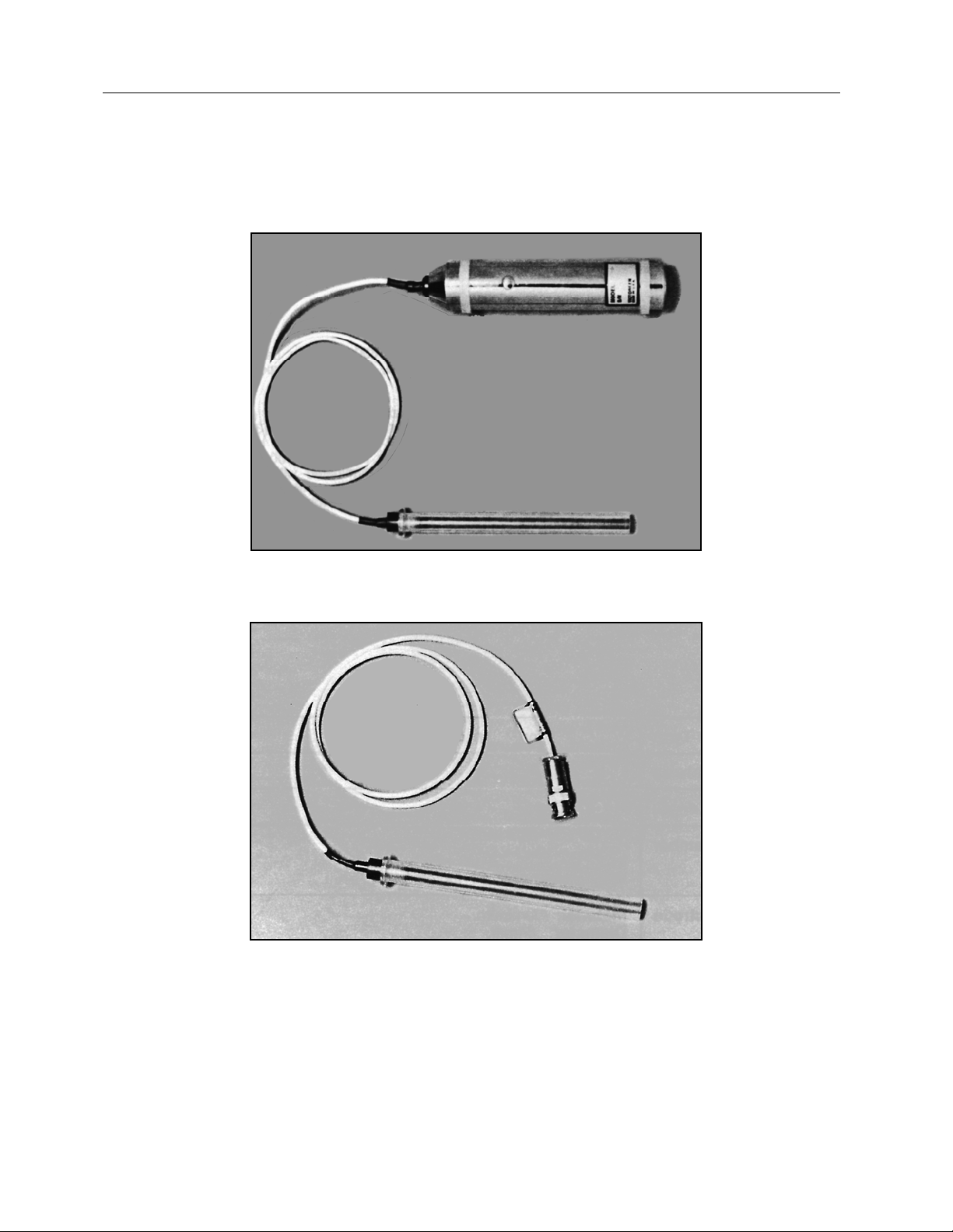
CT Probes, Models 660-6, 500-100, and 6000-100 are designed to be used with Phantoms, Models 6607 and 660-8, to measure exposure produced by Computed Tomography (CT) Scanners.
The probes (Figure 1-1) consist of a pencil type ionization chamber with a sensitive length of 10.0 cm.
The Model 660-6 probe chamber is connected, via 0.9 m (3 ft.) of low noise flexible cable, to a signal
digitizing pre-amplifier. It is designed to be readout on a Model 660 Digital Exposure Meter. The Model
500-100 probe chamber is connected to 0.9 m (3 ft.) of low noise flexible cable terminated with a male
BNC size triaxial connector. It is designed to be readout on a quality electrometer. Model 600-100 (notshown) is similar to the Model 500-100, but designed for the NERO™
The phantoms (Figure 1-2) are designed in accordance with the definition in the FDA Center for Devices
and Radiological Health, performance standard 1020.33 Computed Tomography (CT) equipment, “NCT
Dosimetry Phantom”. Model 660-7 is a body phantom; Model 660-8 is a head phantom.
1
1.2 Specifications
1.2.1 CT Probes
Detector Type
Volume
Sensitive Length
Chamber Material: Clear Acrylic
Electrode Material: Aluminum
Sensitivity
Factory Calibration
Energy Response
Beam Orientation
Phantom Adapter Outside Diameter: 1.27 ± 0.04 cm (0.50 ± 0.015 in)
Model 66O-6
(with Model 660
Readout)
Vented air ionization chamber
3.2 cc
10.0 cm
Inside Diameter: 6.4 mm
Wall Thickness: 54 mg/cm
Diameter: 0.64 mm
10 R cm/nC (nominal)
100 KVCP, 5.5 mm Al hvl
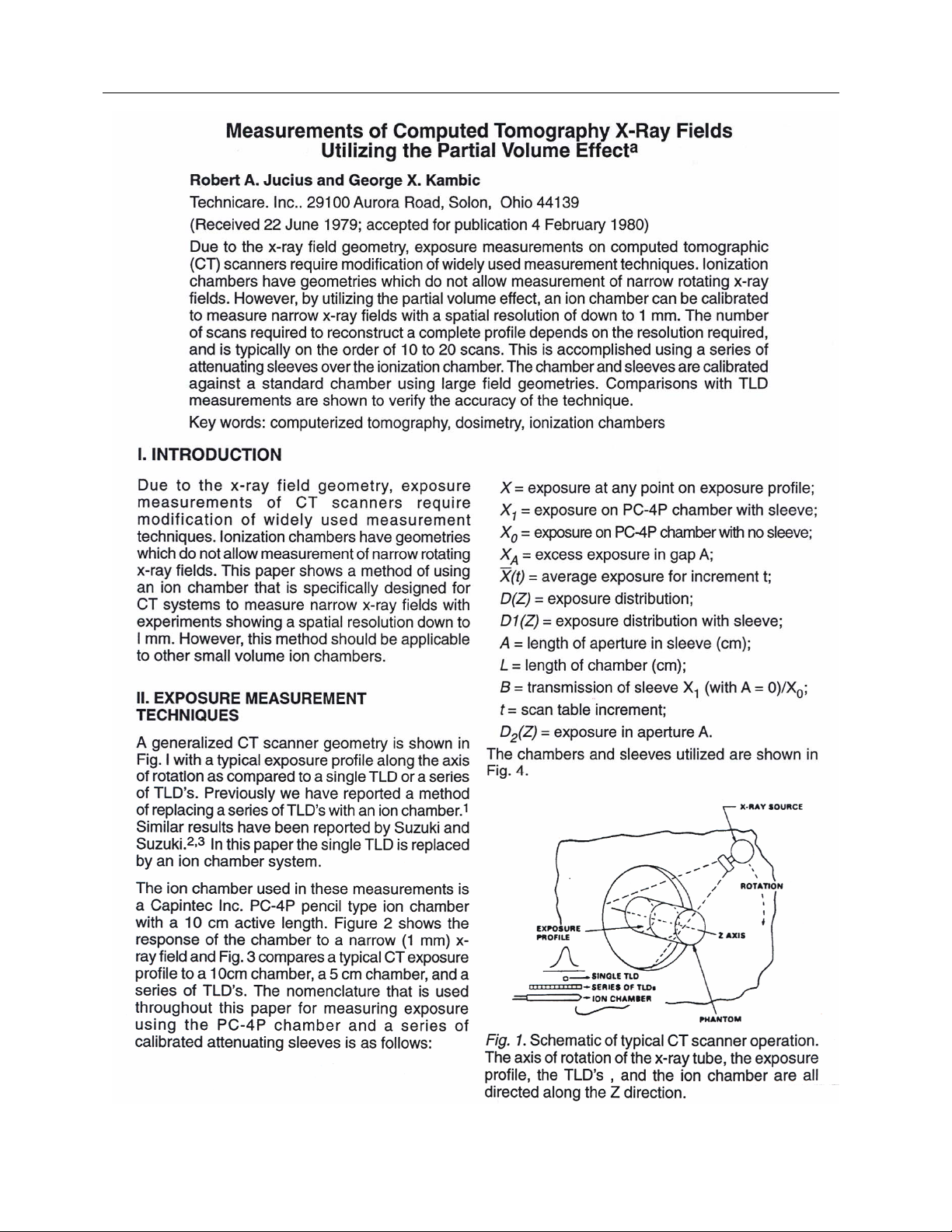
+5%, 1 mm Al to 10 mm Al hvl (see Figure 1-3)
Uniformity (along axis): + 3% over central 90% of active
length (see Figure 1-4)
Normal to chamber axis
Maximum Display: 999 R cm/min, 99.9 R cm
Maximum Resolution: 0.01 R cm/min, 0.001 R cm
2
1-1
Page 6
Victoreen 660-6,660-7,660-8,500-100,6000-100
Operators Manual
Figure 1-1. Model 660-6 and Model 500-100 CT Probes
1-2
Page 7
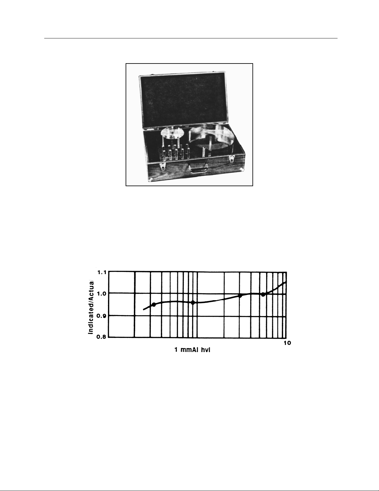
Figure 1-2. Model 660-7 and Model 660-8 Phantoms
Introduction
Specifications
1
Figure 1-3. CT Probe Energy Response (Phantom Adapter Removed)
1-3
Page 8

Victoreen 660-6,660-7,660-8,500-100,6000-100
Operators Manual
Figure 1-4. CT Probe Unit Length Response
Model 660-6
(Cont’d)
Intensity Limits:
Continuous Beam:
985 R/min (1% recombination loss, ion chamber)
1080 R cm/min (electronic preamp limitation)
Pulsed Beam: 1.6 mR/pulse (1% recombination loss)
Maximum Pulse Repetition Rate: 700 Hz
Ion Transit Time: 1.3 ms
Model 500-100
(with 300 Volt
Collection Potential)
Leakage Current:
10 min polarization time: <10
2 hr polarization time: <10
Intensity Limits:
Continuous Beam: 4.86 kR/min (1% recombination loss)
Pulsed Beam: 51.5 mR/pulse (1% recombination loss)
Maximum Pulse Repetition Rate: 3.3 kHz
Ion Transit Time: 0.3 ms
Connector: BNC triaxial
-14
A
-13
A
1-4
Page 9

Introduction
Specifications
1.2.2 Phantoms
Material
Thickness
Diameter
Probe Holes
Volume
Acrylic Plastic
15 cm
Model 660-7 Body Phantom: 32 cm (12.60 in)
Model 660-6 Head Phantom: 16 cm (6.30 in)
Arrangement: One on center, four around periphery (90
degrees apart, 1 cm in from edge)
Inside Diameter: 1.27 cm
3.2 cc
1.3 Receiving Inspection
Upon receipt of the unit:
1. Inspect the carton(s) and contents for damage. If damage is evident, file a claim with the carrier and
notify Fluke Biomedical, Radiation Management Service at 440.248.9300.
2. Remove the contents from the packing material.
3. Verify that all items listed on the packing list have been received and are in good condition.
If any of the listed items are missing or damaged,
notify Fluke Biomedical.
NOTE
1
1.4 Storage
If the unit is to be stored prior to use, pack it in the original container(s), if possible, and store in an
environment free of corrosive materials, fluctuations in temperature and humidity, and vibration and
shock.
The equipment described in this manual is intended
to be used for the detection and measurement of
ionizing radiation. It should be used only by
persons who have been trained in the proper
interpretation of its readings and the appropriate
safety procedures to be followed in the presence of
radiation.
Although the equipment described in this manual is
designed and manufactured in compliance with all
applicable safety standards, certain hazards are
inherent in the use of electronic and radiometric
equipment.
CAUTION
1-5
Page 10

Victoreen 660-6,660-7,660-8,500-100,6000-100
Operators Manual
(Blank Page)
Page 11

Theory of Operation
Theory of Operation
2
Section 2
Theory of Operation
2.1 Theory of Operation
In a phantom, integration of the radiation exposure profile produced by a single scan from a CT scanner
along a line normal to the slice, divided by the table increment, is equal to the average exposure
produced by a series of scans to a central slice at that point. * The line of integration must be of sufficient
length to intercept both the primary beam and the Compton scanner produced in the phantom. The
integral is expressed as R cm.
A long, thin radiation probe can be used for the measurement. The probe should be calibrated in a
uniform field covering its entire sensitive length, with a correction factor determined in the conventional
manner. Subsequent probe readings, multiplied by the correction factor and then by its sensitive length,
will be in units of R cm.
The CT probes are designed especially for CT scanner applications. The correction factor due to their
length (10.0 cm) is built into the probe calibration:
• The Model 660-6, when used with the Model 660, is read directly in R cm or R cm/min.
• The Model 550-100 correction factor is stated in R cm/coulomb
NOTE
In applications where the probes are used to
measure uniform field exposure in terms of R, the
Model 660 readings should be divided by 10 or the
Model 500-100 correction should be divided by 10.
*R. A. Jucius, G. X. Kambic, “Measurements of Computed Tomography X-Ray Fields Utilizing the Partial
Volume Effect”
2-1
Page 12

Victoreen 660-6,660-7,660-8,500-100,6000-100
Operators Manual
(Blank Page)
Page 13

Operation
Operation
Section 3
Operation
3.1 Operation
The following considerations should be noted when using CT Probes and Phantoms:
• The phantom adaptor (built-up sleeve) is designed to provide mechanical protection for the ion
chamber and to properly place the probe’s sensitive volume in the phantom.
• The phantom adaptor should never be removed from the probe in the field; it should only be
removed when necessary and in the calibration laboratory (e.g., to verify probe sensitivity).
• The hole plugs supplied with the phantoms have small 1.5 mm holes through their midpoint. When
the phantom is properly centered in the CT beam, the holes will appear as small rectangles on the
CT scan.
• The ion chamber electrode is not guarded; therefore, after a collection voltage is applied, allow five
minutes for the insulators to polarize.
• If using the Model 660 readout, five minutes after the unit is turned on remove the plug button in the
probe preamp and adjust the zero (while in the Rate Mode).
The Model 660 does not read below zero;
therefore, adjust the zero from a positive reading
down to just zero. Otherwise, appreciable error may
be introduced due to negative leakage.
Use the above guidelines and following procedure to take data
CAUTION
3
1. Position the phantom, readout device, and cable.
2. Connect the probe to the readout device.
3. Turn on the readout device, applying a collection voltage.
4. Run a scan to check that the holes in the hole plugs are visible.
5. Place the probe in the phantom.
6. Place the probe readout in the integrate mode.
7. Wait one minute to be sure there is not excessive leakage.
8. Run scans and record data as required.
3-1
Page 14

Victoreen 660-6,660-7,660-8,500-100,6000-100
Operators Manual
(Blank Page)
Page 15

Probe Calibration
Probe Calibration
Section 4
Probe Calibration
4.1 Probe Calibration
The Models 660-6 and 500-100 probes are factory calibrated with the correction factor built into the
calibration. However, since the NERO™ electrometer is calibrated with the internal ion chamber, it is
impossible to supply a CT probe correction factor that applies to all NEROs. Therefore, the user must
calibrate the probe with the NERO it is to be used with. Use the following procedure:
4
Calibration should be performed on a standard
radiographic x-ray machine rather than a CT
machine.
1. Set the x-ray machine to 100 kVp, 300 mA, and 0.5 sec.
2. Place the probe on the table:
• The source to detector distance (SDD) should be 40 inches.
• The equilibrium sleeve should be in place.
• The probe should be perpendicular to the tube axis to minimize the heel effect.
3. Collimate the beam so that it uniformly irradiates the entire length of the probe.
4. Attach the probe to the NERO detector:
a. Connect the BNC connector to the appropriate jack on the side of the NERO
b. Plug the banana plug into its mating jack.
5. Position, and if necessary shield, the NERO detector so that radiation does not fall on the ion
chamber.
6. Use the detector cable to plug the detector into the NERO unit, plug the unit into AC power, and
turn it on.
7. Verify the mR correction factor by pressing the key sequence F mR on the NERO. The correction
factor should be displayed on the LCD.
If 1.000 is not displayed, enter 1 and press ENT.
8. Set the NERO up for an exposure by pressing the key sequence F 5. Observe the following:
• The display will clear as NERO measures electrometer drift for twelve seconds.
• The NERO will then beep and display 0.0 mR.
9. Make an exposure and record the results.
10. Press NEXT to clear the display.
11. Repeat Steps 9 and10 to obtain a total of five exposures.
NOTE
NOTE
4-1
Page 16

Victoreen 660-6,660-7,660-8,500-100,6000-100
Operators Manual
NOTE
All five exposures should be within 3%.
12. Compute an average of the five exposures. Record the average as the Measured Value.
13. Press EXIT to return the NERO to the Ready condition.
14. Remove and disconnect the CT probe.
15. Place the NERO detector in the center of the beam.
16. Raise the tube 2.25 inches to compensate for the height of the detector box.
17. Make an exposure and record the results.
18. Press NEXT to clear the display.
19. Repeat Steps 17 and 18 to obtain a total of five exposures.
NOTE
All five exposures should be within 3%.
20. Compute an average of the five exposures. Record the average as the True Value.
21. Compute the correction factor for the probe as follows:
cf = 1 x True Value/Measured Value where 1 = the probe length (10 cm).
22. Record the correction factor.
Use the computed correction factor when making CT dose measurements. Enter it into the NERO as the
mR correction factor (by pressing F mR, entering the factor, and pressing ENT). The display will then
read directly in mR cm.
4-2
Page 17

Appendix
Radiation Dosimetry in Computed Tomography
A
Appendix A
Radiation Dosimetry in Computed Tomography
A.1 Radiation Dosimetry in Computed Tomography
This Appendix contains the following Technical Notes article, as published in Volume 7 No. 4 of “Medical
Physics” in Jul / Aug 1980.
Measurements of Computed Tomography X-Ray Fields
Utilizing the Partial Volume Effect
Robert A. Jucius and George X. Kambic
a
A-1
Page 18
Victoreen 660-6,660-7,660-8,500-100,6000-100
Operators Manual
A-2
Page 19

Appendix
Radiation Dosimetry in Computed Tomography
A
A-3
Page 20

Victoreen 660-6,660-7,660-8,500-100,6000-100
Operators Manual
A-4
Page 21

Appendix
Radiation Dosimetry in Computed Tomography
A
A-5
Page 22

Fluke Biomedical
Radiation Management Services
6045 Cochran Road
Cleveland, Ohio 44139
440.498.2564
www.flukebiomedical.com/rms
 Loading...