

Page 1

Getting Started Manual
5730A
Multifunction Calibrator
PN 4290571
August 2013 Rev. 1, 6/15
© 2013-2015 Fluke Corporation. All rights reserved. Specifications are subject to change without notice.
All product names are trademarks of their respective companies.
Page 2

LIMITED WARRANTY AND LIMITATION OF LIABILITY
Each Fluke product is warranted to be free from defects in material and workmanship under
normal use and service. The warranty period is one year and begins on the date of shipment.
Parts, product repairs, and services are warranted for 90 days. This warranty extends only to the
original buyer or end-user customer of a Fluke authorized reseller, and does not apply to fuses,
disposable batteries, or to any product which, in Fluke's opinion, has been misused, altered,
neglected, contaminated, or damaged by accident or abnormal conditions of operation or
handling. Fluke warrants that software will operate substantially in accordance with its functional
specifications for 90 days and that it has been properly recorded on non-defective media. Fluke
does not warrant that software will be error free or operate without interruption.
Fluke authorized resellers shall extend this warranty on new and unused products to end-user
customers only but have no authority to extend a greater or different warranty on behalf of Fluke.
Warranty support is available only if product is purchased through a Fluke authorized sales outlet
or Buyer has paid the applicable international price. Fluke reserves the right to invoice Buyer for
importation costs of repair/replacement parts when product purchased in one country is submitted
for repair in another country.
Fluke's warranty obligation is limited, at Fluke's option, to refund of the purchase price, free of
charge repair, or replacement of a defective product which is returned to a Fluke authorized
service center within the warranty period.
To obtain warranty service, contact your nearest Fluke authorized service center to obtain return
authorization information, then send the product to that service center, with a description of the
difficulty, postage and insurance prepaid (FOB Destination). Fluke assumes no risk for damage in
transit. Following warranty repair, the product will be returned to Buyer, transportation prepaid
(FOB Destination). If Fluke determines that failure was caused by neglect, misuse, contamination,
alteration, accident, or abnormal condition of operation or handling, including overvoltage failures
caused by use outside the product’s specified rating, or normal wear and tear of mechanical
components, Fluke will provide an estimate of repair costs and obtain authorization before
commencing the work. Following repair, the product will be returned to the Buyer transportation
prepaid and the Buyer will be billed for the repair and return transportation charges (FOB
Shipping Point).
THIS WARRANTY IS BUYER'S SOLE AND EXCLUSIVE REMEDY AND IS IN LIEU OF ALL
OTHER WARRANTIES, EXPRESS OR IMPLIED, INCLUDING BUT NOT LIMITED TO ANY
IMPLIED WARRANTY OF MERCHANTABILITY OR FITNESS FOR A PARTICULAR PURPOSE.
FLUKE SHALL NOT BE LIABLE FOR ANY SPECIAL, INDIRECT, INCIDENTAL, OR
CONSEQUENTIAL DAMAGES OR LOSSES, INCLUDING LOSS OF DATA, ARISING FROM
ANY CAUSE OR THEORY.
Since some countries or states do not allow limitation of the term of an implied warranty, or
exclusion or limitation of incidental or consequential damages, the limitations and exclusions of
this warranty may not apply to every buyer. If any provision of this Warranty is held invalid or
unenforceable by a court or other decision-maker of competent jurisdiction, such holding will not
affect the validity or enforceability of any other provision.
Fluke Corporation
P.O. Box 9090
Everett, WA 98206-9090
U.S.A.
Fluke Europe B.V.
P.O. Box 1186
5602 BD Eindhoven
The Netherlands
11/99
Page 3

OPERATOR SAFETY
SUMMARY
WARNING
HIGH VOLTAGE
is used in the operation of this equipment
LETHAL VOLTAGE
may be present on the terminals, observe all safety precautions!
To prevent electrical shock hazard, the operator should not electrically contact the
output HI or sense HI terminals or circuits connected to these terminals. During
operation, lethal voltages of up to 1100 V ac or dc may be present on these
terminals.
When the nature of the operation permits, keep one hand away from equipment to reduce the hazard
of current flowing through vital organs of the body.
Page 4

Page 5

Table of Contents
Title Page
Introduction ........................................................................................................ 1
Safety Information ............................................................................................. 3
Symbols ............................................................................................................. 4
How to Contact Fluke Calibration ..................................................................... 5
Instruction Manuals ........................................................................................... 5
Wideband AC Voltage Module (Option 5730A/03 or 5730A/05)..................... 5
Auxiliary Amplifiers .......................................................................................... 6
5725A Amplifier ........................................................................................... 6
52120A Amplifier ......................................................................................... 7
Support Equipment and Services ....................................................................... 7
732B Direct Voltage Reference Standard ..................................................... 7
732B-200 Direct Volt Maintenance Program (USA Only) ........................... 8
742A Series Resistance Standards ................................................................. 8
Wideband AC Module (Option 5730A/03 or 5730A/05) Calibration
Support .......................................................................................................... 8
The Components of the Calibrator ..................................................................... 8
5730A Calibration .............................................................................................. 9
The Artifact Calibration Process ................................................................... 9
Establish Traceability .................................................................................... 10
Calibration Reports ........................................................................................ 10
Range Adjustment ......................................................................................... 10
DC Zeros ............................................................................................................ 10
Unpack and Inspect the Calibrator ..................................................................... 11
Placement and Rack Mounting .......................................................................... 11
Cooling Considerations ...................................................................................... 12
Fuse Replacement .............................................................................................. 12
Clean the Air Filter ............................................................................................ 14
Clean the Exterior .............................................................................................. 15
Connect to Mains Power .................................................................................... 15
Connect a 5725A Amplifier ............................................................................... 15
Connect a 52120A Amplifier ............................................................................. 15
Front-Panel Features .......................................................................................... 15
Rear-Panel Features ........................................................................................... 20
General Specifications ....................................................................................... 22
Electrical Specifications .................................................................................... 24
AC Voltage Specifications ............................................................................ 25
i
Page 6

5730A
Getting Started Manual
Resistance Specifications .............................................................................. 31
DC Current Specifications ............................................................................. 35
AC Current Specifications ............................................................................. 37
Wideband AC Voltage (Option 5730A/03 and 5730A/05) Specifications
(99 % Confidence Level) ............................................................................... 40
52120A Specifications when Operated with the 5730A ................................ 41
52120A Electrical Performance Limits ......................................................... 42
Operated within 5730A Control Loop (all current ranges) ........................... 42
Coverage factor k=2.58 (99 % confidence level) ...................................... 42
Coverage factor k=2.00 (95 % confidence level) ...................................... 43
52120A/COIL 3 kA 25-Turn Coil ................................................................. 44
52120A/COIL 6 kA 50-Turn Coil ................................................................. 44
ii
Page 7

List of Tables
Table Title Page
1. Symbols .................................................................................................................. 4
2. Auxiliary Amplifier Data ....................................................................................... 6
3. Standard Equipment ............................................................................................... 11
4. Replacement Fuses ................................................................................................. 13
5. Front-Panel Features .............................................................................................. 16
6. Rear-Panel Features ............................................................................................... 20
iii
Page 8

5730A
Getting Started Manual
iv
Page 9

List of Figures
Figure Title Page
1. Access the Fuse ...................................................................................................... 13
2. Air Filter Access .................................................................................................... 14
3. Front-Panel Features .............................................................................................. 16
4. Rear-Panel Features ............................................................................................... 20
v
Page 10

5730A
Getting Started Manual
vi
Page 11

Introduction
The Fluke Calibration 5730A Calibrator (the “Calibrator” or the “Product”) can calibrate
a wide variety of electrical measurement instruments. The 5730A Calibrator maintains a
high accuracy over a wide ambient temperature range. This accuracy lets the Calibrator
test instruments in any environment, and eliminates the restrictions to calibrate only in a
temperature-controlled standards laboratory. The Calibrator can calibrate precision
multimeters that measure ac or dc voltage, ac or dc current, and resistance. The Calibrator
also is available with a Wideband AC Voltage option which extends this workload to
include RF voltmeters.
Specifications are provided at the end of this manual. The Product is a fullyprogrammable precision source of:
• DC voltage to 1100 V
• AC voltage to 1100 V, with output available from 10 Hz to 1.2 MHz
• AC and DC current to 2.2 A, with output available from 10 Hz to 10 kHz
• Resistance in values from 1 Ω to 100 MΩ, plus a short
• Optional wideband ac voltage from 300 μV to 3.5 V into 50 Ω (-57 dBm to
+24 dBm), 10 Hz to 30 MHz (5730A/03) or 50 MHz (5730A/05)
Features of the 5730A Calibrator include:
• Internal environmentally-controlled references that let the Calibrator maintain full
performance over a wide ambient temperature range.
• Automatic meter error calculation obtained through the use of a simple output adjust
knob.
• Keys that multiply and divide the output value by 10. This simplifies work on meters
with calibration points at decade multiples of a fraction of full-scale.
• Programmable entry limits used to restrict the levels that can be entered into the
Calibrator. This prevents access to levels that may be harmful to equipment or
personnel.
• Continuous display of Calibrator specifications at the selected operation point,
calibration interval, and specification confidence level.
1
Page 12

5730A
Getting Started Manual
• An auxiliary current binding post to calibrate meters with separate current inputs
without the need to move cables.
• Real-time clock and calendar for date stamping reports and reminders issued to
perform the dc zeros calibration procedure within the required interval.
• Offset and scaling modes that simplify linearity tests of multimeters.
• Variable phase reference signal output and phase-lock input.
• Interface for the Fluke Calibration 5725A Amplifier.
• Interface for the Fluke Calibration 52120A Amplifier.
• Standard IEEE-488 (GPIB) interface, that complies with ANSI/IEEE Standards
488.1-1987 and 488.2-1987.
• EIA/TIA-574 Standard RS-232 serial data interface for remote control of the
Calibrator.
• Universal Serial Bus (USB) 2.0 high-speed interface device port for remote control of
the Calibrator.
• Integrated 10/100/1000BASE-T Ethernet port for network connection remote control
of the Calibrator.
• Extensive internal self-testing and diagnostics of analog and digital functions
• USB Host port to save calibration reports to a flash drive.
• Visual Connection Management output terminals illuminate to help show correct
cable connection configurations.
• Soft Power - automatic selection of line voltage/frequency.
• LCD Color VGA display with touch panel overlay.
• A traceable calibration procedure for all modes and ranges that requires only 10 V,
1 Ω, and 10 kΩ external standards, with only occasional independent verification.
• Automated calibration check that provides added confidence between calibration
recalls, and data that can be used to document and characterize Calibrator
performance between calibration recalls.
2
Page 13

Multifunction Calibrator
Safety Information
Safety Information
A Warning identifies conditions and procedures that are dangerous to the user. A
Caution identifies conditions and procedures that can cause damage to the Product or
the equipment under test.
Warnings
To prevent possible electrical shock, fire, or personal injury:
• Read all safety information before you use the Product.
• Carefully read all instructions.
• Do not use the Product around explosive gas, vapor, or in
damp or wet environments.
• Use this Product indoors only.
• Do not put the Product where access to the mains power
cord is blocked.
• Use only the mains power cord and connector approved for
the voltage and plug configuration in your country and rated
for the Product.
• Replace the mains power cord if the insulation is damaged
or if the insulation shows signs of wear.
• Make sure the ground conductor in the mains power cord is
connected to a protective earth ground. Disruption of the
protective earth could put voltage on the chassis that could
cause death.
• Do not use an extension cord or adapter plug.
• Do not operate the Product with covers removed or the case
open. Hazardous voltage exposure is possible.
• Do not use the Product if it operates incorrectly.
• Do not connect to live output terminals. The Product can
supply voltages that can cause death. Standby mode is not
sufficient to prevent electrical shock.
• Do not apply more than the rated voltage, between the
terminals or between each terminal and earth ground.
• Use only cables with correct voltage ratings.
3
Page 14
5730A
Getting Started Manual
Symbols
Symbol Definition Symbol Definition
• Do not touch exposed metal on banana plugs, they can have
voltages that could cause death.
• Do not touch voltages >30 V ac rms, 42 V ac peak, or 60 V dc.
• Use the Product only as specified, or the protection
supplied by the Product can be compromised.
• Use only specified replacement fuses.
• Have an approved technician repair the Product.
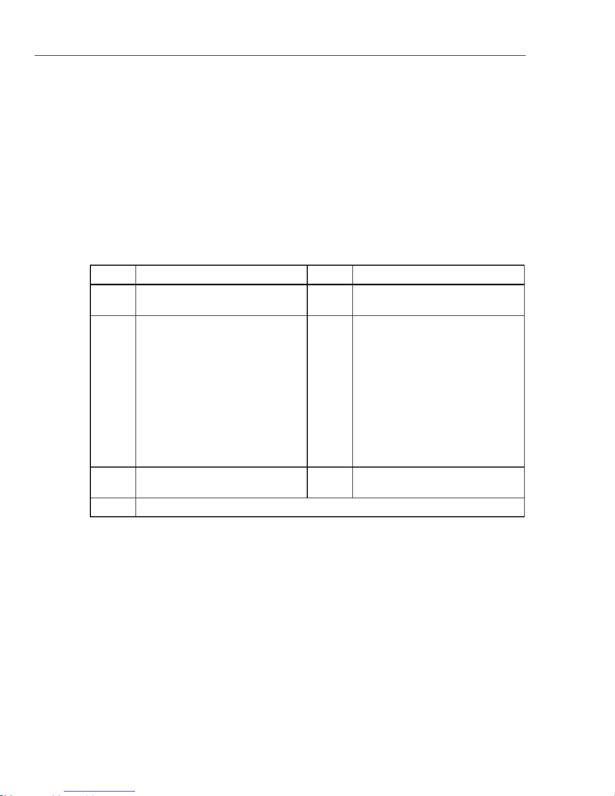
The symbols shown in Table 1 can be found in this manual or on the Calibrator.
Table 1. Symbols
WARNING.RISK OF DANGER.
This product complies with the WEEE
Directive marking requirements. The
affixed label indicates that you must not
discard this electrical/electronic product
in domestic household waste. Product
Category: With reference to the
equipment types in the WEEE Directive
Annex I, this product is classed as
category 9 "Monitoring and Control
Instrumentation" product. Do not
dispose of this product as unsorted
municipal waste.
Certified by CSA Group to North
American safety standards.
WARNING. HAZARDOUS VOLTAGE.
Risk of electric shock.
Conforms to European Union
directives.
Conforms to relevant Australian EMC
standards.
Conforms to relevant South Korean EMC Standards.
4
Page 15

Multifunction Calibrator
How to Contact Fluke Calibration
How to Contact Fluke Calibration
To contact Fluke Calibration, call one of the following telephone numbers:
• Technical Support USA: 1-877-355-3225
• Calibration/Repair USA: 1-877-355-3225
• Canada: 1-800-36-FLUKE (1-800-363-5853)
• Europe: +31-40-2675-200
• Japan: +81-3-6714-3114
• Singapore: +65-6799-5566
• China: +86-400-810-3435
• Brazil: +55-11-3759-7600
• Anywhere in the world: +1-425-446-6110
To see product information or download manuals and the latest manual supplements, visit
Fluke Calibration’s website at www.flukecal.com.
To register your product, visit http://flukecal.com/register-product.
Instruction Manuals
The 5730A Calibrator ships with:
• 5730A Getting Started
• 5730A Operators Manual (provided on CD-ROM or a printed copy is available for
purchase through the Fluke Calibration Service Department)
To order, refer to the Fluke Calibration Catalog or contact a Fluke Calibration sales
representative. See “How to Contact Fluke Calibration”.
Wideband AC Voltage Module (Option 5730A/03 or 5730A/05)
The Wideband AC Voltage Module (Option 5730A/03 or 5730A/05) can be installed in
the 5730A Calibrator. The module is a high-accuracy, low-noise, extremely flat ac
voltage source to calibrate RF voltmeters, with a frequency range of 10 Hz to 30 MHz
(5730A/03) or 50 MHz (5730A/05). Output is in seven ranges from 300 μV (-57 dBm) to
3.5 V (+24 dBm) through a Type-N coaxial connector into a 50 Ω load. The output level
is selected in volts or dBm through either the front panel controls or under remote
control.
The wideband module also functions with the Calibrator output adjust controls that
display the error of a wideband meter in either percentage of output or in decibels.
Included with the wideband module is a Type-N output cable, a 50 Ω terminator, an N(f)
to BNC(m) adapter, and a BNC(f) to double banana plug adapter. The wideband module
is calibrated to the end of its standard-equipment output cable.
5
Page 16
5730A
Getting Started Manual
Auxiliary Amplifiers
The Fluke Calibration Model 5725A and 52120A amplifiers are available to extend the
high voltage performance and current range of the 5730A Calibrator.
Interface connectors on the Calibrator rear panel accept cables to directly operate a
5725A and/or 52120A. Multiple amplifiers can be connected to the Calibrator at the same
time, but only one output can be active at a time. Once the amplifiers are connected and
configured in the Product Setup Menu, amplifier operation is controlled by the Calibrator.
A maximum of three 52120As can be connected to provide a maximum of 360 A rms ac
or 300 A dc current when their outputs are connected in parallel.
See Chapter 4 of the Operators Manual for instructions to operate both amplifiers. The
general specifications at the end of this manual include specifications to operate the
5730A Calibrator with both amplifiers. For other amplifier specifications, refer to their
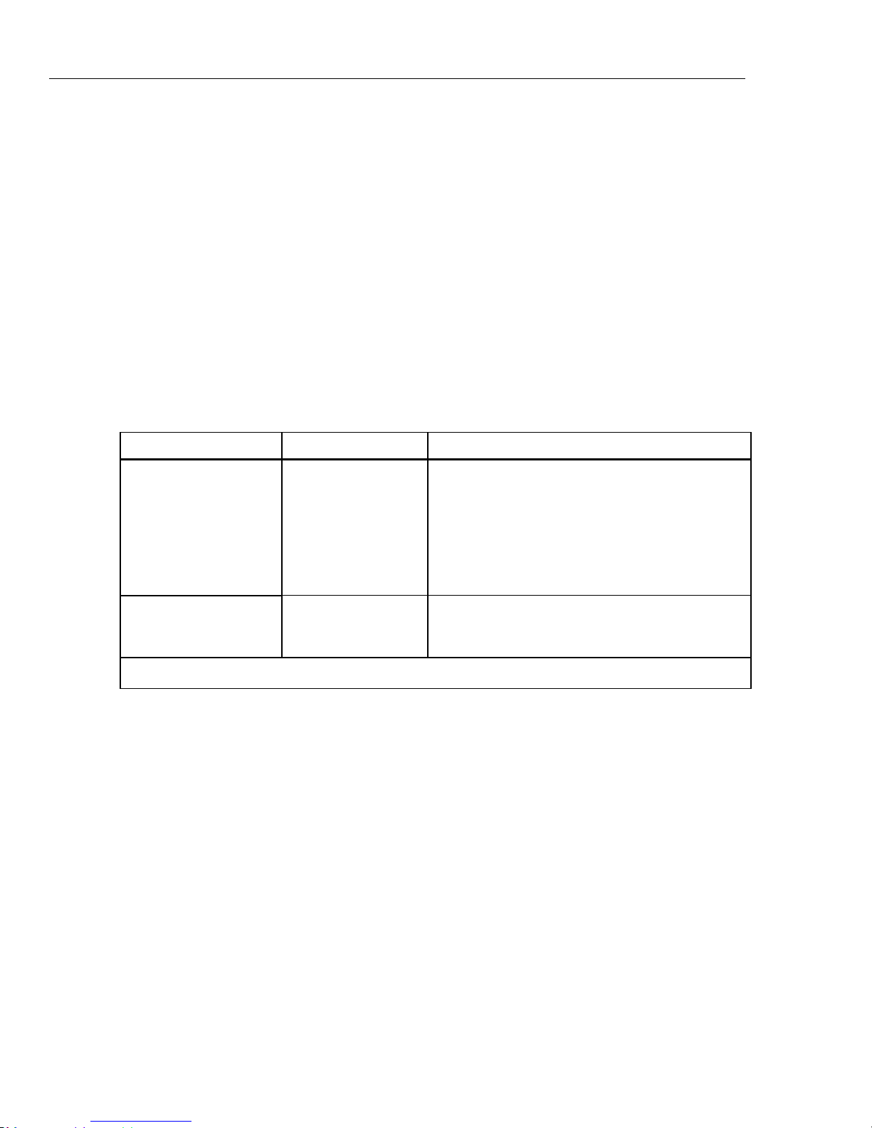
instruction manuals. Table 2 summarizes the extended capabilities offered by the 5725A
and 52120A. Brief descriptions of the extended capabilities follow.
Table 2. Auxiliary Amplifier Data
Model Mode Range
20 V rms to 1100 V rms up to 70 mA, 40 Hz to
AC Volts
5725A Amplifier
DC Amps 0 A to ±11 A
AC Amps 1 A rms to 11 A rms, 40 Hz to 10 kHz
52120A
Transconductance
Amplifier
[1] Up to three 52120As may be connected, providing a total current of up to 300 A dc or 360 A rms.
[1]
DC Amps 0 A to ±100 A
AC Amps 0.2 A rms to 120 A rms, 10 Hz to 10 kHz
30 kHz (50 mA < 5 kHz)
220 V rms to 750 V rms up to 70 mA, 30 kHz to
100 kHz
5725A Amplifier
The Fluke Calibration 5725A Amplifier is an external unit that operates under calibrator
control. It extends ac voltage drive capabilities and both ac and dc current output range.
The amplifier adds these capabilities to the 1100 V ac range of the 5730A Calibrator with
no compromise in accuracy:
• Frequency limits at higher voltage increase to 100 kHz at 750 V, 30 kHz at 1100 V.
• Load limit increases to 70 mA for frequencies above 5 kHz.
• Capacitive drive increases to 1000 pF, subject to the maximum output current.
A separate set of binding posts on the front panel of the 5725A supplies extended-range
ac and dc current outputs. Since most meters have a separate input terminal for the highcurrent ranges, this eliminates the need to change cables during a procedure. The 5725A
can also be configured to source all current (both standard calibrator-generated current
and its own current) through the 5725A binding posts.
6
Page 17

Multifunction Calibrator
Support Equipment and Services
52120A Amplifier
The Fluke Calibration 52120A Transconductance Amplifier is an external unit that
operates under calibrator control to extend the ac and dc current output range of the
5730A Calibrator. A maximum of three 52120A amplifiers can be connected, as much as
tripling the current output available. The 52120A amplifier can:
• Accept full scale dc or ac inputs of 2 volts or 200 mA from any calibrator, signal
generator or power supply
• Deliver proportional output current in ranges of 2 A, 20 A or 120 A at frequencies to
10 kHz
• Offer enhanced accuracy to 140 ppm when used in closed-loop mode with a 6105A
Electrical Power Standard
• Operate in parallel with one or two other 52120As to deliver 240 A or 360 A
• Source current with compliance voltage of 4.5 V rms or 6.4 V peak
• Drive inductive loads to 1 mH
• Drive optional current coils to deliver test currents of 3000 A or 6000 A
Support Equipment and Services
Fluke Calibration supports calibration requirements with precision, high-quality
equipment and a wide range of services. Depending on the calibration needs, location,
and capabilities, the 5730A Calibrator can be supported independently or with Fluke
Calibration services for part, or all support needs. The subsequent paragraphs describe the
support equipment and services offered by Fluke Calibration for the Calibrator. For
specifications and ordering instructions for this support equipment and other Fluke
Calibration instruments, refer to the Fluke Calibration catalog, or contact a representative
at a Fluke Calibration Sales and Service Center. See “How to Contact Fluke Calibration”.
732B Direct Voltage Reference Standard
The Fluke Calibration 732B is a rugged, easily transported solid state direct voltage
reference standard with a highly predictable 10 V output. The 732B can be shortcircuited, even for extended periods of time, without damage or loss of stability. It
maintains full specified stability over a temperature span of 18 °C to 28 °C.
The 5730A Calibrator uses a 10 V reference standard such as the Fluke Calibration 732B
in its semi-automated calibration procedure to establish external voltage traceability.
Chapter 7 of the Operators Manual describes this procedure.
7
Page 18

5730A
Getting Started Manual
732B-200 Direct Volt Maintenance Program (USA Only)
742A Series Resistance Standards
The Fluke Calibration 732B-200 Direct Volt Maintenance Program provides laboratories
with NIST-traceable 10 V calibration uncertainty as low as 0.6 parts per million (ppm).
The program maintains the 732B that is kept in the laboratory. To do this:
1. Fluke Calibration sends a calibrated Fluke Calibration-owned 732B standard,
together with all-necessary connection cables and instructions for comparison with a
customer 10 V reference standard.
2. The customer takes a series of readings over five days, and returns the results to the
Fluke Calibration Standards Laboratory.
3. The Fluke Calibration Standards Laboratory assigns a value to the customer 10 V
standard relative to the NIST legal volt and sends a report of calibration.
The 5730A Calibrator uses 1 Ω and 10 kΩ resistor standards such as the 742A Series in
its semi-automated calibration procedure to establish external traceability of resistance
and current. Chapter 7 of the Operators Manual describes this procedure.
The 742A Resistance Standards are constructed of arrays of Fluke Calibration wirewound
precision resistors and are ideally suited as support standards for the Calibrator. Stability
of the resistance transfer standards and their temperature coefficients make them ideal for
easy transport to the Calibrator work environment.
Wideband AC Module (Option 5730A/03 or 5730A/05) Calibration Support
The Wideband AC Module (Option 5730A/03 or 5730/05) requires two kinds of
calibration: gain and flatness. Gain constants are checked and recalibrated as part of the
normal 5730A Calibrator semi-automated calibration process.
Since frequency flatness is determined by such stable parameters as circuit geometry and
dielectric constants, flatness of the Wideband AC Module has excellent long-term
stability. This stability gives the Wideband AC Module a two-year calibration cycle for
flatness calibration. Flatness calibration is required only infrequently, and can be done
when the Calibrator is returned to a standards laboratory for periodic verification.
Chapter 7 of the Operators Manual contains the wideband gain and flatness calibration
procedures.
The Components of the Calibrator
The 5730A Calibrator is configured internally as an automated calibration system, with
process controls and consistent procedures. Internal microprocessors control all functions
and monitor performance with the use of a switching matrix to route signals between
modules. Complete automatic internal diagnostics, both analog and digital, confirm
operational integrity.
Reference amplifiers maintain dc accuracy and stability. Reference amplifiers have the
lowest noise and best stability. Reference amplifiers in the Calibrator go through special
selection processes that include long-term aging to ensure high reliability and
performance well within specifications.
8
Page 19

Multifunction Calibrator
5730A Calibration
The Calibrator achieves its exceptional ac voltage accuracy by the use of a patented Fluke
Calibration rms sensor to make real-time ac/dc comparison measurements. The Fluke
Calibration rms sensor is similar in principle to the traditional thermal voltage converter,
but has a shorter time constant, virtually no reversal error, higher signal-to-noise ratio,
and better frequency response. In the Calibrator, one Fluke Calibration rms sensor serves
as an ac/dc or ac/ac transfer standard to develop gain and flatness correction constants
during calibration. The second Fluke Calibration rms sensor continuously monitors and
corrects output voltage during operation.
A patented 26-bit digital-to-analog converter (DAC) lets the Calibrator precisely vary its
output. This is a pulse-width-modulated DAC with linearity typically better than 0.2 ppm
of full scale. As with the other internal functions, the linearity of the DAC is
automatically checked during calibration and analog diagnostics.
5730A Calibration
The 5730A Calibrator makes use of internal check standards and measurement systems.
As a result, it can be completely calibrated in place to full specifications with a small
number of convenient, portable, environmentally-tolerant standards available from Fluke
Calibration. This procedure is traceable to military standard requirements.
When manufactured, each Product is calibrated and thoroughly verified with process
metrology and calibration standards traceable to the International System of units (SI)
through well-recognized national metrology institutes. A certificate of calibration that is
accredited to ISO 17025 is included.
The calibration verification procedure is recommended every 2 years or as required by
established policies. This procedure involves no adjustments. It ensures internal processes
are in control, and establishes parallel external traceability paths for internal functions
such as ac transfers that are never adjusted or corrected.
The Artifact Calibration Process
Calibration requires only three external standards or artifacts: 10 V, 1 Ω, and 10 kΩ.
Environmentally-controlled internal check standards provide the primary reference
points. A stored table of calibration constants defines additional reference points for
controlling the output. Traceable calibration and adjustment to the specified level of
performance is accomplished in a semi-automated process that revises this table.
When finished with artifact calibration, but before the new constants are saved, the
5730A Calibrator presents the proposed adjustments as +/- ppm of range and percentage
change in specification for each range and function. A list of changes can be sent to the
computer through the serial port, USB device port, Ethernet port, or the IEEE-488 port
using the remote command: CAL_RPT? CHECK. Also on completion of calibration, the
Calibrator shows the largest proposed change.
Calibration can be completed as far as deriving and printing the proposed adjustments
without entering the calibration protection passcode. To save the changes in non-volatile
memory to adjust future outputs from the Calibrator, the passcode must be entered from
the front panel or with a remote command. The passcode entry menu is shown on the
display when necessary.
9
Page 20

5730A
Getting Started Manual
Establish Traceability
Calibration Reports
Traceability to national standards is established as follows:
• Except for the internal ac/dc transfer standard, the internal check standards are
directly calibrated by traceable external standards every time the Calibrator is
calibrated.
• The internal ac/dc transfer standard is never adjusted, so its traceability is not
disturbed by calibration. Infrequent verification is done in the traditional way, by
comparing selected ac voltage outputs with an external dc voltage standard through
an external ac/dc transfer standard. Fluke Calibration recommends this to be done
every two years or as determined by the policy of your organization.
• Infrequent independent verification is also done on stable parameters, such as
frequency flatness, determined more by circuit geometry and dielectric constants than
time.
The 5730A Calibrator stores two sets of calibration constants: the set currently in use and
the old set from the previous calibration. This gives the Calibrator the ability at any time
to produce a calibration report of the differences between the present settings and the
settings that were in effect before the last calibration. The report shows shifts in various
output values from before to after the most recent calibration for each range and function
in +/- ppm of range and in percentage of specification limit. The report can be saved to a
USB drive or retrieve it from a host computer through either the RS-232, USB device
port, Ethernet port, or IEEE-488 interface.
Range Adjustment
After calibration, further fine adjustments can be made to each range. Range adjustments
are optional and they are not necessary to meet total uncertainty specifications. However,
they can help to align the Calibrator closer to in-house standards.
Before range calibration is done, first do the Artifact Calibration as described later in this
manual. This is to calibrate the ranges that will not be adjusted. It also performs an initial
adjustment for each range, and supplies flatness corrections for ac functions.
DC Zeros
DC Zeros is a quick, automatic process that corrects offset errors that increase with time
on several output ranges. If a 5725A Amplifier is attached, it also zeros the 11 A dc
range. This process takes approximately 2 ½ minutes (plus an additional 30 seconds for
the 5725A).
To execute dc zeros, from the normal operation screen:
1. Touch Setup Menu to show the Setup Menu. See the “Setup Menu” section of
Chapter 4 in the Operators Manual.
2. Touch the Calibration menu.
3. Touch Run DC Zero to start the dc zeros routine. The status of the dc zero
calibration is shown as the Calibrator progresses through a series of steps. When
completed, the Calibrator shows “Calibration complete”.
If the Calibrator is not warmed up, the display prompts to continue or
cancel the DC Zeros function.
Note
4. Touch Close to proceed with Calibrator use.
10
Page 21
Multifunction Calibrator
Unpack and Inspect the Calibrator
Unpack and Inspect the Calibrator
The 5730A Calibrator ships in a container that prevents shipping damage. Inspect the
Calibrator carefully for damage, and immediately report any damage to the shipper.
Instructions for inspection and claims are included in the shipping container.
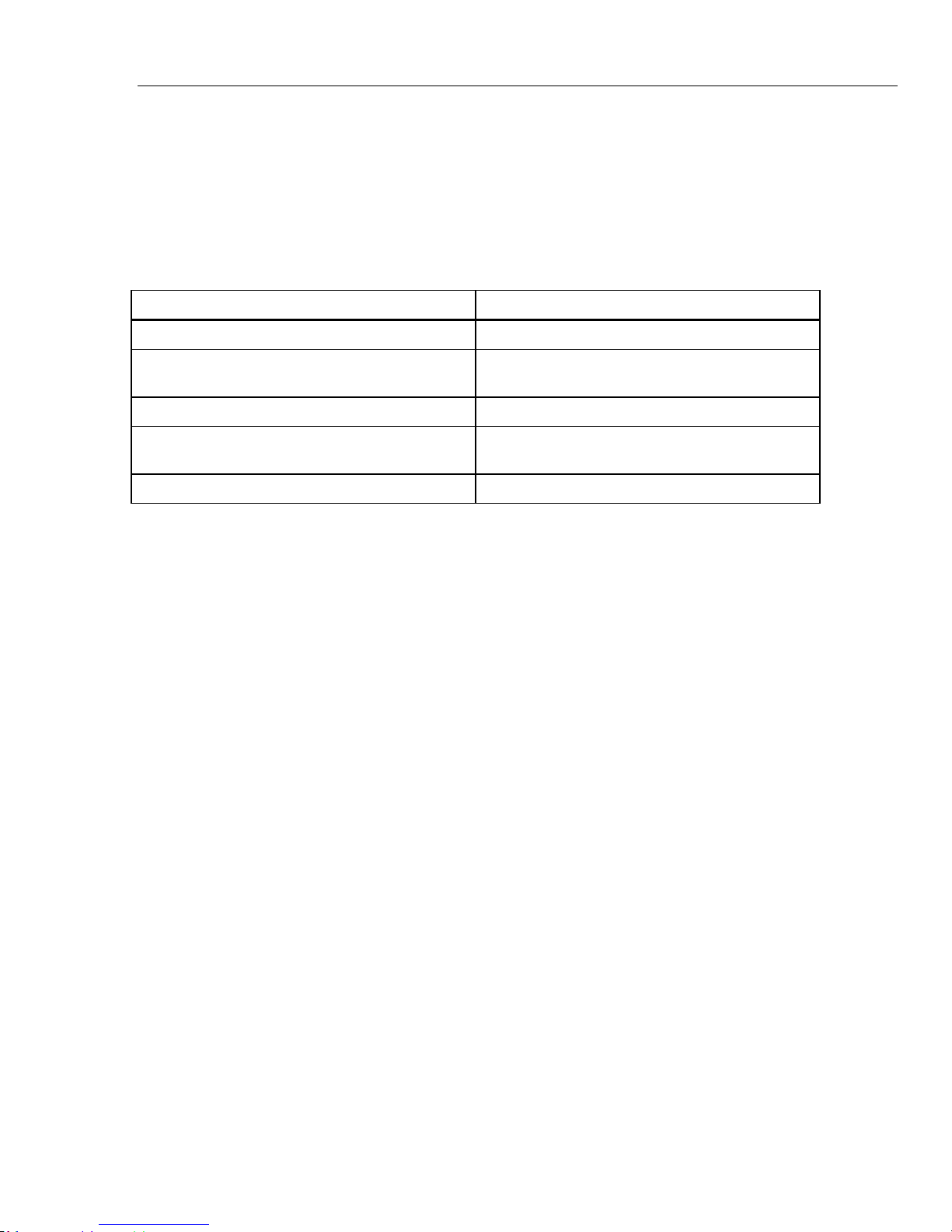
When the Calibrator is unpacked, check for all the standard equipment listed in Table 3
and check the shipping order for additional items ordered.
Table 3. Standard Equipment
Item Model or Part Number
Calibrator 5730A
Mains Power Cord
5730A Getting Started 4290571
5730A Manual CD (Containing the Operators
Manual)
Certificate of Calibration No part number
See Table 2-2 and Figure 2-1 in the Operators
Manual.
4290580
Placement and Rack Mounting
Put the 5730A Calibrator on top of a bench or mount in a standard-width, 24-inch
(61-cm) deep equipment rack. For bench-top use, the Calibrator has non-slipping,
non-marring feet. To mount the Calibrator in an equipment rack, use the Rack Mount
Kit (Model Y5737) or the Rack Ear Kit (Model Y5738). Instructions are included
with the kit.
Warnings
To prevent possible electrical shock, fire, or personal injury, do
not restrict access to the Calibrator mains power cord. The
mains power cord is the mains disconnecting device. If access
to the power cord is inhibited by rack mounting, a properlyrated accessible mains disconnecting switch must be provided
within reach as part of the installation.
11
Page 22

5730A
Getting Started Manual
Cooling Considerations
Fuse Replacement
Caution
Damage caused by overheating can occur if the area around the
air intake is restricted, the intake air is too warm, or the air filter
becomes clogged.
Adhere to these rules to lengthen the life of the 5730A Calibrator and enhance its
performance:
• The area around the air filter must be at least 3 inches from nearby walls or rack
enclosures.
• The exhaust perforations on the sides of the Calibrator must be clear of obstructions.
• The air that enters the Calibrator must be room temperature. Make sure that exhaust
from another instrument is not directed into the fan inlet.
• Clean the air filter every 30 days or more frequently if the Calibrator is operated in a
dusty environment. Instructions for cleaning the air filter are later in this manual.
Access the fuse from the rear panel. The fuse rating label below the fuse holder shows the
correct replacement fuse ratings for each operating voltage.
Warning
To prevent possible electrical shock, fire, or personal injury:
• Turn the Product off and remove the mains power cord.
Stop for two minutes to let the power assemblies discharge
before you open the fuse door.
• Replace a blown fuse with exact replacement only for
continued protection against arc flash.
• Use only specified replacement fuses, see Table 4.
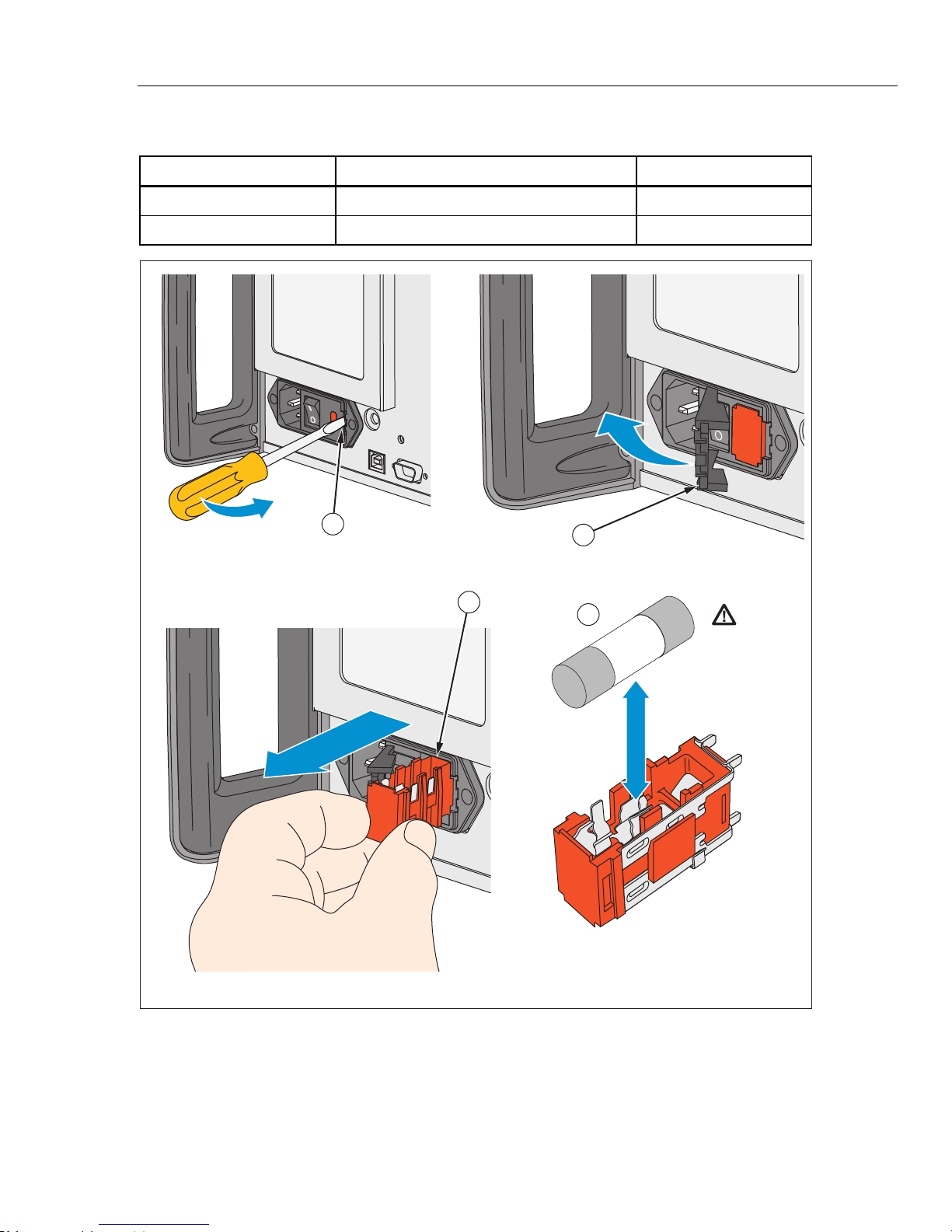
To access the fuse, refer to Figure 1:
1. Disconnect the mains power cord.
2. With a standard screwdriver, release the fuse holder door.
3. Pull out the fuse holder.
4. If necessary, replace the fuse.
5. Reinsert the fuse holder.
6. Close the fuse holder door.
12
Page 23
Multifunction Calibrator
Fuse Replacement
Table 4. Replacement Fuses
Line Voltage Range Fuse Description Fluke Part Number
100 V – 120 V T 3 A 250 V 109280
220 V – 240 V T 1.5 A 250 V 109231
115V
1
3
115V
2
4
P
RSR
1
1
1
V
5
1
0
V
5
3
V
2
Figure 1. Access the Fuse
hhp003.eps
13
Page 24
5730A
Getting Started Manual
Clean the Air Filter
Caution
Damage caused by overheating can occur if the area around the
fan is restricted, the intake air is too warm, or the air filter
becomes clogged.
To prevent Product damage, make sure that the filter is
completely dry before reinstallation.
The air filter must be removed and cleaned at least every 30 days, or more frequently if
the Calibrator is operated in a dusty environment. The air filter is accessible from the rear
panel of the Calibrator.
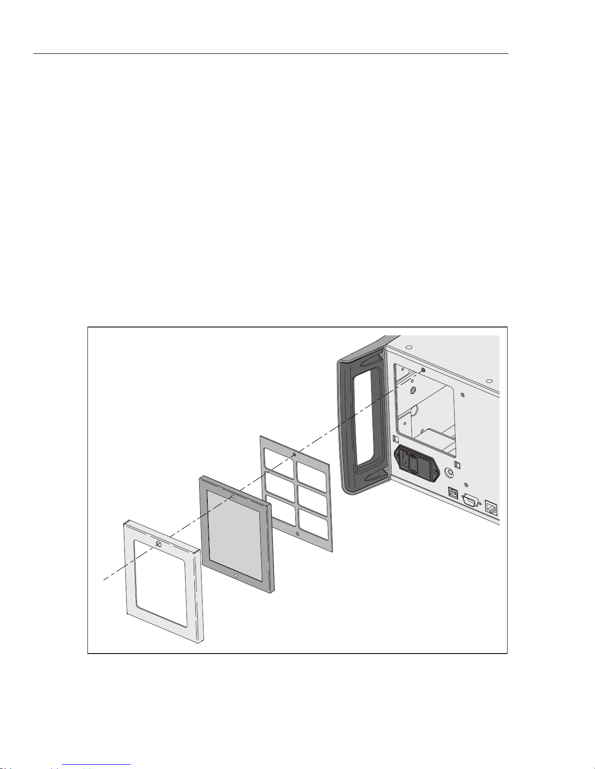
To clean the air filter, refer to Figure 2:
1. Disconnect line power.
2. Unscrew the knurled screw at the top of the air filter and pull the filter retainer
downwards (it is hinged at the bottom) to remove the filter.
3. Clean the filter by washing it in soapy water. Rinse and dry it thoroughly.
4. Reinstall the filter and the knurled screw.
14
Figure 2. Air Filter Access
hhp026.eps
Page 25

Multifunction Calibrator
Clean the Exterior
Clean the Exterior
To keep the 5730A Calibrator looking new, clean the case, front panel keys, and display
with a soft cloth slightly dampened with either water or a non-abrasive mild cleaning
solution that is not harmful to plastics.
Caution
Do not use aromatic hydrocarbons or chlorinated solvents for
cleaning. They can damage the plastic materials used in the
Product.
Connect to Mains Power
Warning
To prevent shock hazard, connect the factory-supplied threeconductor mains power cord to a properly-grounded power
outlet. Do not use a two-conductor adapter or extension cord,
as it will break the protective ground connection. If a twoconductor mains power cord must be used, a protective
grounding wire must be connected between the ground
terminal and earth ground before you connect the mains power
cord or operate the Product.
Connect a 5725A Amplifier
The 5730A Calibrator provides an interface connector for the Fluke 5725A Amplifier.
Designate the active amplifier for voltage and current boost in the Setup Menu, as
detailed in Chapter 4 of the Operators Manual. Refer to the 5725A Instruction Manual for
the installation procedure.
Connect a 52120A Amplifier
The 5730A Calibrator provides an interface connector for the Fluke 52120A
Transconductance Amplifier. Designate the active amplifier for current boost in a Setup
Menu, as detailed in Chapter 4 of the Operators Manual. Refer to the 52120A Users
Manual for the installation procedure.
Front-Panel Features
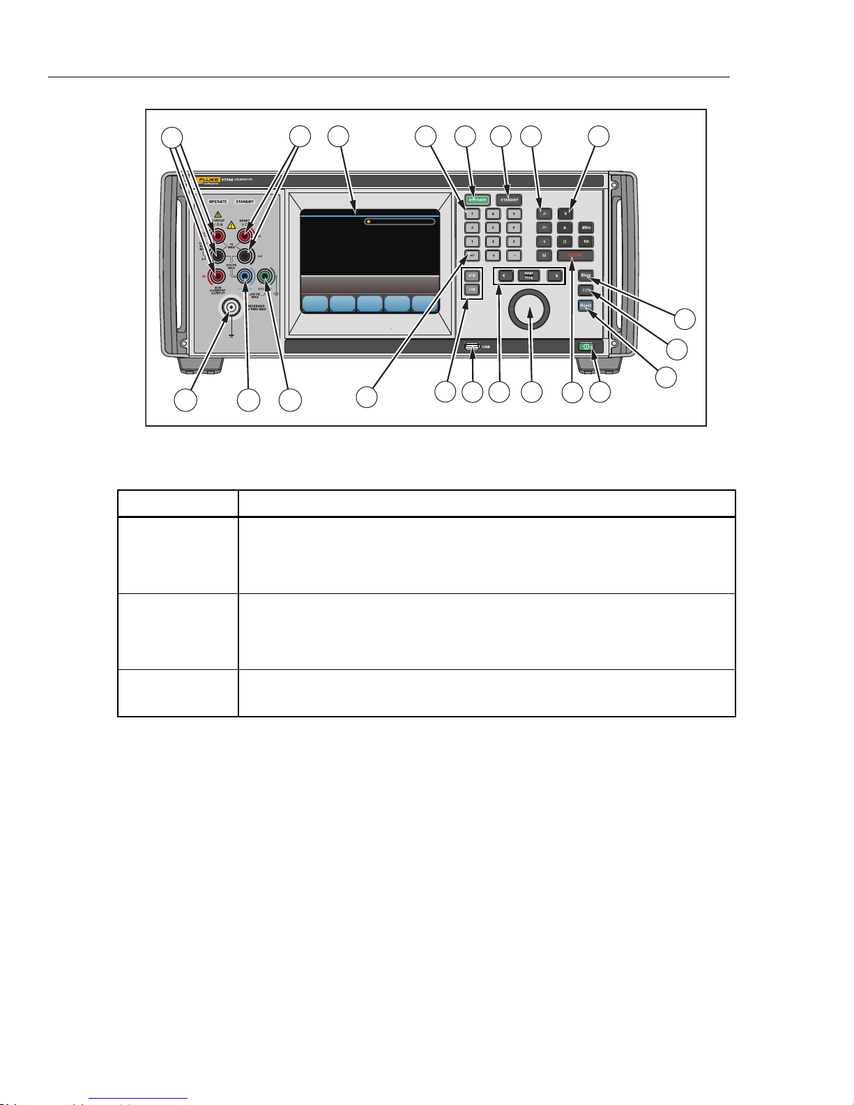
Front-panel features (including all controls, displays, indicators, and terminals) are shown
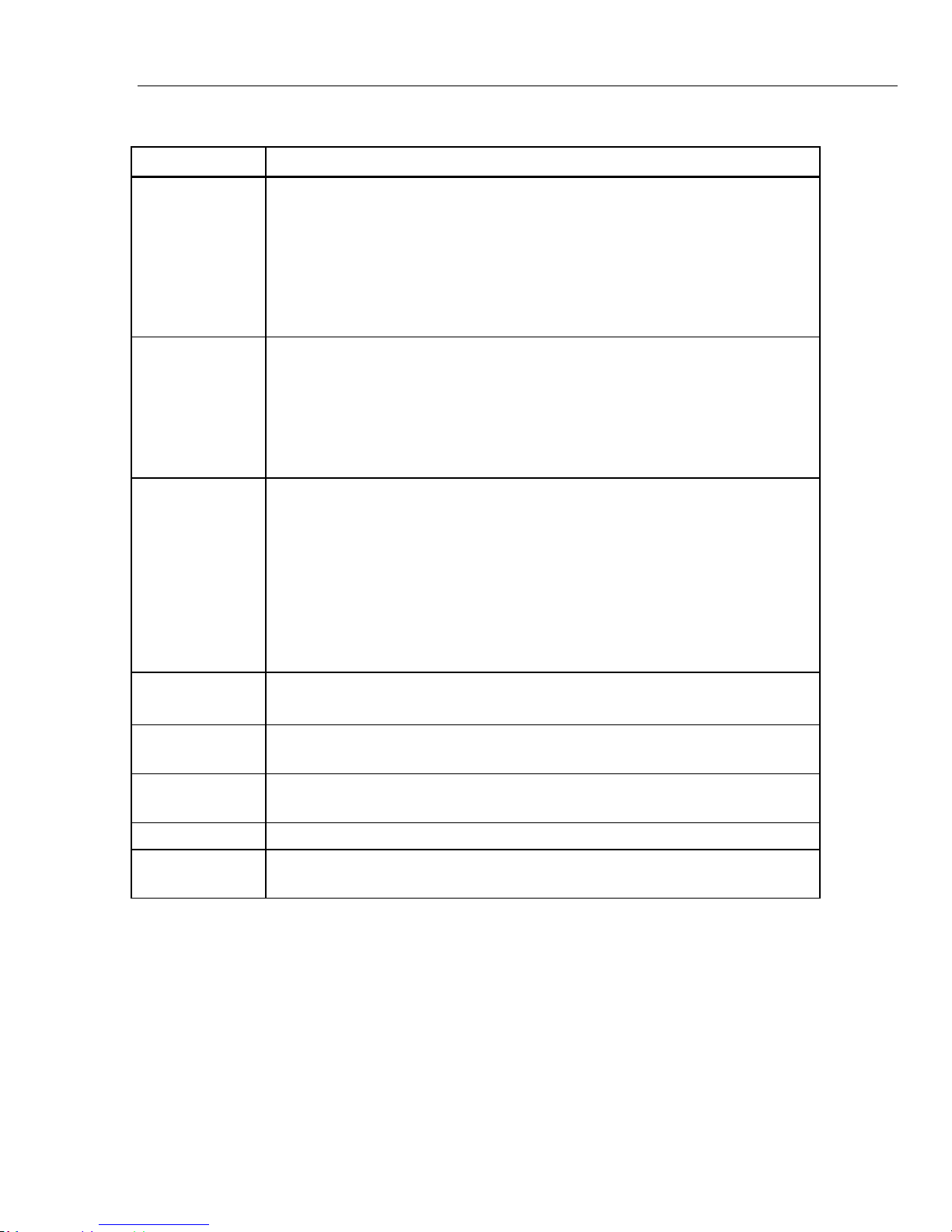
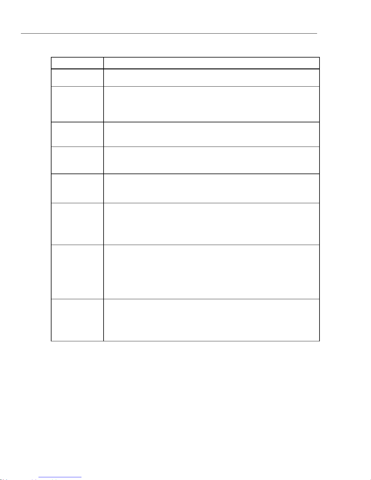
in Figure 3. Each front-panel feature is briefly described in Table 5.
15
Page 26
5730A
Getting Started Manual
20
19 1718
21
3
1
16
2
15
14
54
12
13
6
7
8
9
10
11
hhp006.eps
Figure 3. Front-Panel Features
Table 5. Front-Panel Features
Item Description
The color touch-sensitive display shows the output amplitude, frequency, and other
active conditions and messages. The display provides controls not available with
the keys alone. The Calibrator interface is made up of multiple menus, described in
Chapter 4 of the Operators Manual.
Numbered keys to enter the output amplitude, frequency, and other data such as
the time and date. To enter a value, push the digits of the output value, a multiplier
key (if necessary), and an output function key. Then push
for an output of 20 mV, push
.
. For example,
activates the programmed output.
16
Page 27
Multifunction Calibrator
Front-Panel Features
Table 5. Front-Panel Features (cont.)
Item Description
deactivates the programmed output. The output automatically changes to
STANDBY if:
• is pushed
• The output voltage is changed from <22 V to >22 V
• The output location changes
• The output function changes. An exception to this is that the output stays
operational when functions are changed between ac and dc voltage.
Multiplier keys to select output value multipliers. For example, if
is entered, the Calibrator output value is 33 mV. The multiplier keys are:
micro (10-6)
-3
milli (10
kilo (10
mega (10
Output function keys. The output functions are:
)
3
)
6
)
Decibels relative to 1 mW
Voltage
Current
Resistance
Frequency
When Hz is entered, the Calibrator automatically switches to ac. When a new
signed (+ or -) output value is entered without specifying Hz, the Calibrator
automatically switches back to dc.
Backspace (Bksp) key. As a new output value is entered, use this key to delete the
last key entry.
The CE (Clear Entry) key clears a value entry in progress.
The Reset key returns the Calibrator to its initial power-up state.
Power button. Push the lighted power button to turn on or off the Calibrator.
The ENTER key changes the output value just keyed in with the numerical,
multiplier, and output function keys explained above.
17
Page 28
5730A
Getting Started Manual
Item Description
Table 5. Front-Panel Features (cont.)
GROUND
Binding Post
V GUARD
Binding Post
[1]
Turn the Edit knob to the right to increase the output value of the active-edit digit.
Turn the Edit knob to the left to decrease the output value of the active-edit digit.
Error mode / edit keys
moves the active-edit digit one decimal place to the left.
switches the active-edit field between the amplitude and frequency.
moves the active-edit digit one decimal place to the right.
Front USB port. Calibration report data can be saved to a flash drive inserted into
this port. The Calibration report process is explained in Chapter 7 of the Operators
Manual.
Multiplier keys
- multiplies the present output by 10.
- divides the present output by 10.
Invert output key. If the output function is dc voltage, current, ac voltage entered in
dBm, or a wideband output entered in dBm, push
polarity of the output. If the output function is ac voltage or current, push
to change the output to dc.
If the Calibrator is the location of the ground reference point in a system, the
GROUND binding post can be used to connect other instruments to earth ground.
The chassis is normally connected to earth ground through the three-conductor line
cord instead of through the earth ground binding post. Refer to "Cable Connection
Instructions" in Chapter 4 of the Operators Manual for details. Included with the
Calibrator is a brass strap that connects GROUND to V GUARD.
The V GUARD binding post provides an external connection point for the internal
voltage guard. For a UUT with floating (ungrounded) inputs, the V GUARD should
be connected to LO internally (External Guard OFF). For a UUT with a grounded
input, the V GUARD must be externally connected to the grounded UUT input
(External Guard on). The maximum allowable potential between the V GUARD
connector and chassis ground is 20 V peak. Refer to "When to use the External
Voltage Guard" and "Cable Connection Instructions" in Chapter 4 of the Operators
Manual for details.
to toggle the
The WIDEBAND connector is a Type "N" connector that provides a connection
WIDEBAND
Connector
[1]
point for output from the Option 5730A/03 or 5730A/05 Wideband AC Module.
Wideband output specifications are stated for output levels present at the end of its
3-foot 50 Ω coaxial cable terminated into a 50 Ω purely resistive load. The
connector shell is connected to chassis ground. Refer to Chapter 4 of the Operators
Manual for connecting and operating instructions for the wideband module.
18
Page 29

Multifunction Calibrator
Front-Panel Features
Table 5. Front-Panel Features (cont.)
Item Description
Connection points for ac and dc current and voltage output, and resistance. The
function of each OUTPUT binding post is defined below:
LO
The common binding post for all output functions including 5725A amplified voltage
output, but not Option 5730A/03 or 5730A/05 Wideband AC or other auxiliary
amplifier output.
OUTPUT
Binding Posts
[1]
SENSE Binding
Posts
[1]
HI
The active binding post for all output functions including 5725A amplified voltage
output, but not Option 5730A/03 or 5730A/05 Wideband AC or other auxiliary
amplifier output.
AUX CURRENT OUTPUT
An optional active binding post for current. It is convenient to use the AUX
CURRENT OUTPUT binding post when calibrating a UUT with a separate current
input terminal. Refer to "Connect the Calibrator to the UUT" in Chapter 4 of the
Operators Manual for instructions for use of this binding post.
The SENSE binding post is used with resistance and voltage functions for sensing
at the UUT after the external sense has been selected by the touch of External
Sense or by remote command.
External sensing should be used in the dc voltage function when the UUT draws
enough current to produce a significant voltage drop in the cables, and in the
resistance function when the UUT has a four-wire ohms input and the Calibrator is
set to 100 kΩ or less. External sensing can also be used in the two-wire ohms
function to allow the two-wire compensation circuitry to the UUT terminals. Refer to
"When to use External Sensing," "Four-Wire Vs. Two-Wire Resistance
Connections," and "Cable Connection Instructions" in Chapter 4 of the Operators
Manual for external sensing instructions and illustrations of SENSE connections.
[1] Visual Connection Management Terminals. The appropriate terminals light up in green when
is pushed, whether in STANDBY or OPERATE. The terminals offer visual guidance for cable
connections for specific functions, protect the user by indicating which terminals are active, and
protecting the calibrator from damage from incorrect connections.
19
Page 30
5730A
Getting Started Manual
Rear-Panel Features
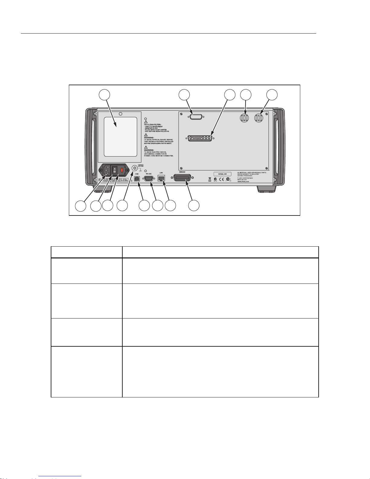
Rear-panel features (including all terminals, sockets, and connectors) are shown in
Figure 4. Each rear-panel feature is briefly described in Table 6.
768
Item Description
Fan Filter
52120A
Transconductance
Amplifier Connector
5725A Amplifier
Connector
VARIABLE PHASE
OUT BNC Connector
1
12
Figure 4. Rear-Panel Features
Table 6. Rear-Panel Features
The filter covers the air intake to keep dust and debris out of chassis. Fans
inside the Calibrator provide a constant cooling air flow throughout the
chassis. Circuitry inside the Calibrator monitors correct operation of the
internal fans.
Provides the analog and digital interface for the Fluke 52120A
Transconductance Amplifier. After the 52120A is connected to the 52120A
AMPLIFIER connector, control the 52120A from the Calibrator front panel
or by remote commands. Refer to "Auxiliary Amplifier Use" in Chapter 4 of
the Operators Manual for details.
Provides the analog and digital interface for the Fluke 5725A Amplifier.
After the 5725A is connected to the 5725A AMPLIFIER connector, control
the 5725A from the Calibrator front panel or by remote commands. Refer to
"Auxiliary Amplifier Use" in Chapter 4 of the Operators Manual for details.
Provides access to a variable-phase nominal 2.5 V rms sine-wave signal,
intended for a 3 kΩ load. The phase of this signal can be adjusted with the
arrow keys and rotary knob (or by remote commands) to lead or lag the
main Calibrator output signal by up to 180 degrees. The connector shell is
not connected directly to chassis ground. It is connected internally to the
OUTPUT LO binding post. The maximum allowable potential between the
connector shell and chassis ground is 20 V peak. Refer to "Variable Phase
Output" in Chapter 4 of the Operators Manual for details.
1311109
3 52
4
hhp009.eps
20
Page 31
Multifunction Calibrator
Rear-Panel Features
Table 6. Rear-Panel Features (cont.)
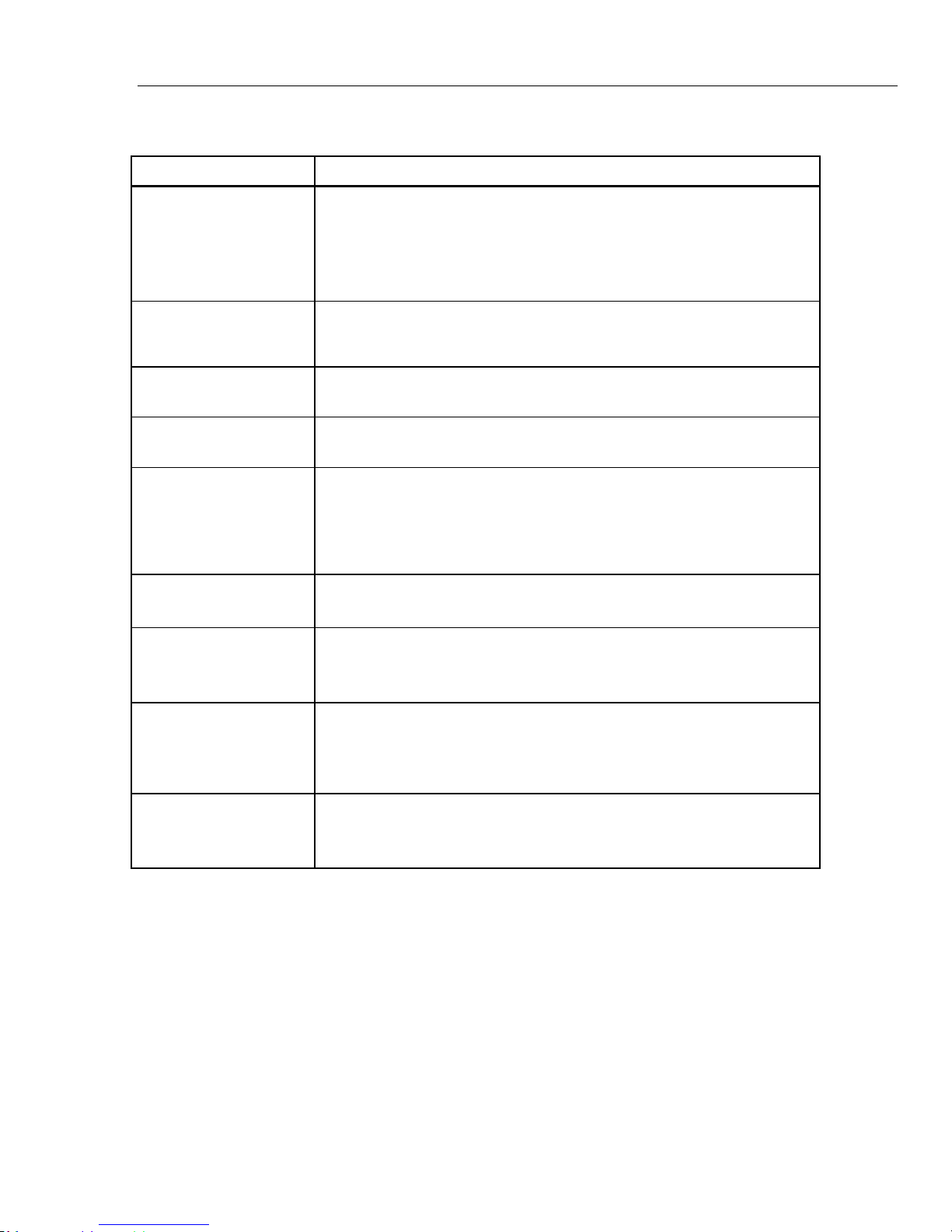
Item Description
Provides the input for an external signal onto which the Calibrator can be
PHASE LOCK IN
BNC Connector
phase locked. (1 V rms to 10 V rms, 10 kΩ input impedance.) The
connector shell is not connected directly to chassis ground. It is connected
internally to the OUTPUT LO binding post. The maximum allowable
potential between the connector shell and chassis ground is 20 V peak.
Refer to "Phase Locking to an External Signal," in Chapter 4 of the
Operators Manual for details.
AC PWR INPUT
Connector
A grounded male three-prong connector that accepts the mains power cord.
Master ON/OFF Switch
F1 Fuse Holder
Chassis Ground
Binding Post
Rear USB Port
RS 232 Connector
Ethernet Connector
IEEE-488 Connector
This switch must be in the ON (I) position before the soft power button on
the front panel will function.
Line power fuse. Refer to "Fuse Replacement" for fuse rating information
and the fuse replacement procedure.
A binding post that is internally grounded to the chassis. If the Calibrator is
the location of the ground reference point in a system, this binding post can
be used for connecting other instruments to earth ground. (The chassis is
normally connected to earth ground through the three-conductor line cord
instead of through the earth ground binding post.) Refer to "Connect the
Calibrator to the UUT" in Chapter 4 of the Operators Manual for details.
USB port for remote control of the Calibrator. Chapter 5 of the Operators
Manual describes how to connect to the USB interface. Refer Chapter 6 of
the Operators Manual for remote programming instructions.
A male (DTE) serial port connector for remote control of the Calibrator.
Chapter 5 of the Operators Manual describes proper cabling and how to set
up the Serial interface and connect to it. Refer to Chapter 6 of the
Operators Manual for remote programming instructions.
100 Base/T Ethernet connector for remote control of the Calibrator. Chapter
5 of the Operators Manual describes proper cabling, how to set up the
interface, and how to transmit data from the Calibrator. Chapter 5 of the
Operators Manual also describes how to use the Ethernet interface for
remote control.
A standard interface connector for operating the Calibrator in remote control
as a Talker or Listener on the IEEE-488 Bus. Refer to Chapter 5 of the
Operators Manual for bus connection. Refer to Chapter 6 of the Operators
Manual for remote programming instructions.
21
Page 32

5730A
Getting Started Manual
General Specifications
Warm-Up Time ....................................................... Twice the time since last warmed up, to a maximum of 30 minutes.
System Installation ............................................... Rack mount kits available.
Standard Interfaces .............................................. IEEE-488, RS-232, USB 2.0 device, Ethernet, 5725A, 52120A, phase
Temperature Performance
Operating ............................................................ 0 °C to 50 °C
Calibration ........................................................... 15 °C to 35 °C
Storage ............................................................... -40 °C to 75 °C
Relative Humidity
Operating ............................................................ <80 % to 30 °C, <70 % to 40 °C, <40 % to 50 °C
Storage ............................................................... <95 %, non-condensing. A power stabilization period of four days may
Safety ..................................................................... IEC 61010-1: Overvoltage Category II, Pollution Degree 2
Operating Altitude ................................................. 2000 m maximum
Guard Isolation ...................................................... 20 V
Electromagnetic Compatibility (EMC)
IEC 61326-1 (Controlled EM environment) ......... IEC 61326-2-1; CISPR 11: Group 1, Class A
USA (FCC) .......................................................... 47 CFR 15 subpart B, this product is considered an exempt device per
Korea (KCC) ....................................................... Class A Equipment (Industrial Broadcasting & Communication
Line Power
Line Voltage
5730A ............................................................. 100 V-120 V, 220 V- 240 V ±10 %
5725A ............................................................. 100 V, 110 V, 115 V, 120 V, 200 V, 220 V, 230 V, 240 V, ±10 %
Line Frequency ............................................... 47 Hz-63 Hz
Maximum Power
5730A ............................................................. 300 VA
5725A ............................................................. 750 VA
lock in (BNC), phase reference out (BNC).
be required after extended storage at high temperature and humidity.
Group 1 equipment has intentionally generated and/or use
conductively coupled radio-frequency energy which is necessary for
the internal functioning of the equipment itself.
Class A equipment is equipment suitable for use in all establishments
other than domestic and those directly connected to a low voltage
power supply network which supplies buildings used for domestic
purposes.
Emissions which exceed the levels required by CISPR 11 can occur
when the equipment is connected to a test object. The equipment may
not meet the immunity requirements of 61326-1 when test leads and/or
test probes are connected.
clause 15.103
Equipment)
This product meets requirements for industrial (Class A)
electromagnetic wave equipment and the seller or user should take
notice of it. This equipment is intended for use in business
environments and not to be used in homes.
22
Page 33
Multifunction Calibrator
General Specifications
Weight
5730A ................................................................. 27 kg (62 lb)
5725A ................................................................. 32 kg (70 lb)
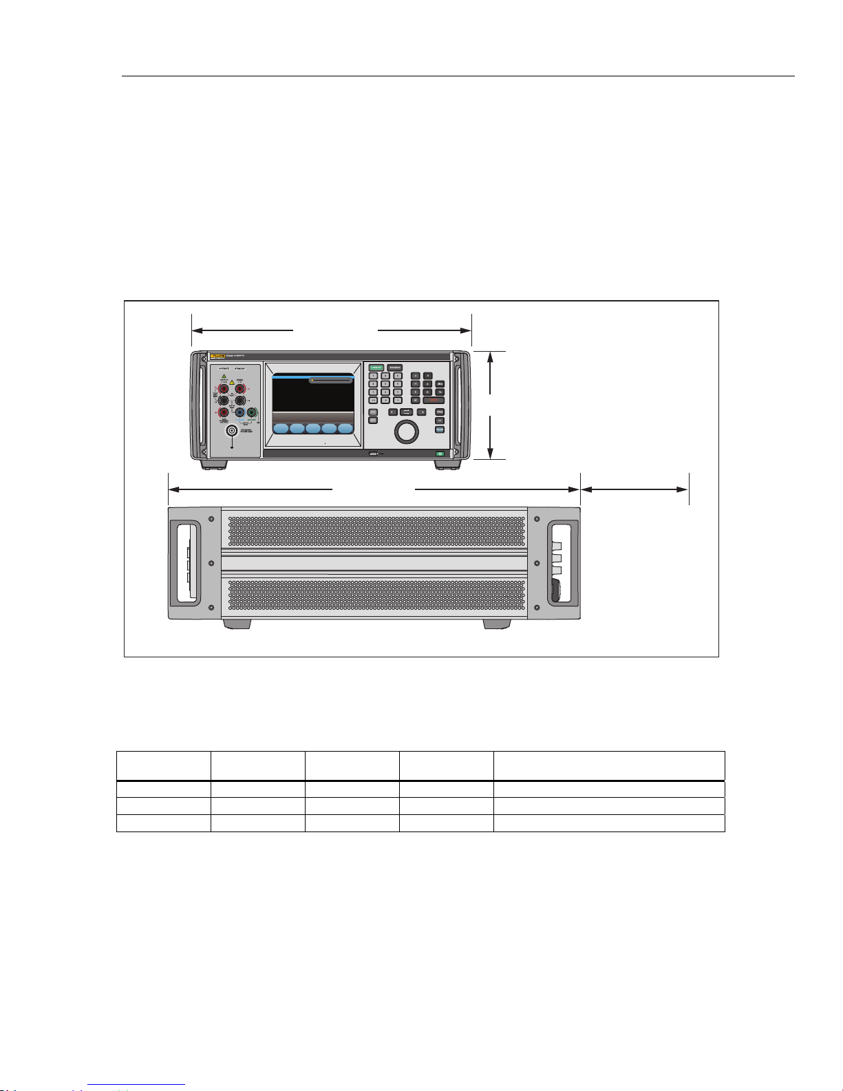
Size
5730A
Height ............................................................. 17.8 cm (7 in), standard rack increment, plus 1.5 cm (0.6 in) for feet
Width ............................................................... 43.2 cm (17 in), standard rack width
Depth .............................................................. 64.8 cm (25.5 in), overall; 59.4 cm (23.4 in), rack depth
5725A
Height ............................................................. 13.3 cm (5.25 in)
Width and Depth ............................................. Both units project 5.1 cm (2 in) from rack front.
43.2 cm (17 in)
17.8 cm (7 in)
64.8 cm (25.5 in)
6.35 cm (2.5 in)
For cable
access
Figure 5. Product Dimensions
Artifact Calibration Standards Requirements
The following external standards are necessary to calibrate the 5730A to the listed specification. Each external
standard used must have an uncertainty equal to or less than the listed uncertainty limit.
Fluke Standard
732B Voltage 10 V 1.5 ppm dc volts, ac volts, dc current, ac current
742A-1 Resistance
742A-10k Resistance
Traceable
Quantity
Nominal Value Uncertainty Limit
1 Ω
10 kΩ
10 ppm
2 ppm
5730A Specifications Susceptible to
Uncertainty Limit
1 Ω, 1.9 Ω
ac current, dc current 10 Ω to 100 MΩ
hhp002.eps
23
Page 34
5730A
Getting Started Manual
Electrical Specifications
The product specifications describe the Absolute Instrumental Uncertainty of the Product. The product specifications
include stability, temperature, and humidity; within specified limits, linearity, line and load regulation, and the reference
standard measurement uncertainty. The product specifications are provided at a 99 %, k=2.58, normally distributed and a
95 %, k=2, normally distributed level of confidence. Fluke Calibration guarantees product performance to the 99 % level of
confidence.
The relative specifications are provided for enhanced accuracy applications. The specifications apply when range
constants are adjusted (see "Range Calibration"). To Calculate an enhanced absolute specification from the relative
accuracy specification, it is necessary to combine the uncertainty of your external standards with the pertinent relative
specifications.
Specifications are valid after allowing a warm-up period of 30 minutes, or twice the time the Product has been turned off.
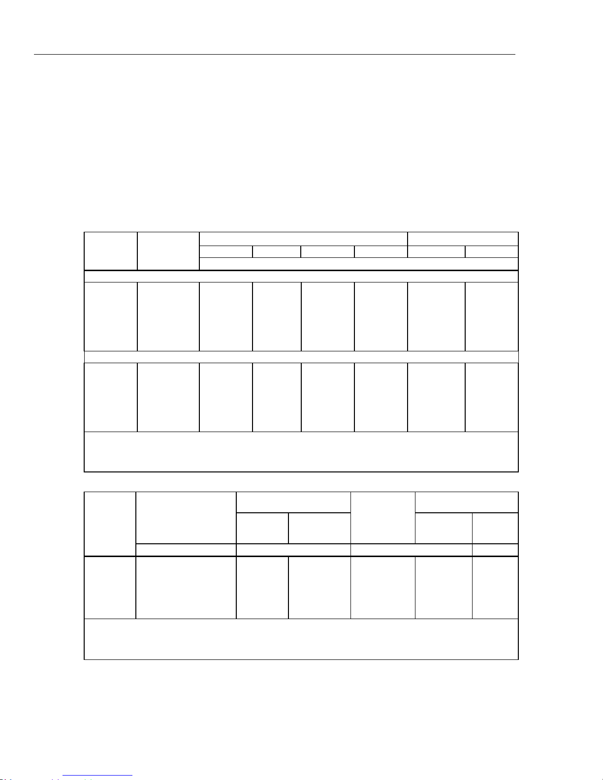
DC Voltage Specifications
Range Resolution
99 % Confidence Level
220 mV 10 nV 5 + 0.5 7 + 0.5 8 + 0.5 9 + 0.5 2 + 0.4 2.5 + 0.4
2.2 V 100 nV 3.5 + 0.8 4 + 0.8 4.5 + 0.8 6 + 0.8 2 + 0.8 2.5 + 0.8
11 V
22 V
220 V
1100 V
95 % Confidence Level
220 mV 10 nV 4 + 0.4 6 + 0.4 6.5 + 0.4 7.5 + 0.4 1.6 + 0.4 2 + 0.4
2.2 V 100 nV 3 + 0.7 3.5 + 0.7 4 + 0.7 5 + 0.7 1.6 + 0.7 2 + 0.7
11 V
22 V
220 V
1100 V
Notes:
Perform the DC Zero calibration every 30 days. In addition, perform the DC Zero calibration after powering up the unit the first time after
unpacking following a shipment or if exposed to an environmental change of greater than 5 °C.
1. For radiated EMI fields >400 MHz and <500 MHz, add 1 ppm.
1 μV
1 μV
10 μV
100 μV
1 μV
1 μV
10 μV
100 μV
5730A DC Voltage Specifications
Absolute / ±5 °C from calibration temperature
24 Hours 90 Days 180 Days 1 Year 24 Hours 90 Days
±(ppm output
[1]
+ μV)
2.5 + 3 3 + 3 3.5 + 3 4 + 3 1 + 3 1.5 + 3
2.5 + 5 3 + 5 3.5 + 5 4 + 5 1 + 5 1.5 + 5
3.5 + 50 4 + 50 5 + 50 6 + 50 2 + 50 2.5 + 50
5 + 500 6 + 500 7 + 500 8 + 500 2.5 + 400 3 + 400
2 + 2.5 2.5 + 2.5 3 + 2.5 3.5 + 2.5 0.8 + 2.5 1.2 + 2.5
2 + 4 2.5 + 4 3 + 4 3.5 + 4 0.8 + 4 1.2 + 4
3 + 40 3.5 + 40 4 + 40 5 + 40 1.6 + 40 2 + 40
4 + 400 4.5 + 400 6 + 400 6.5 + 400 2 + 400 2.4 + 400
Relative ±1 °C
24
DC Voltage Secondary Performance Specifications and Operating Characteristics
Range
Stability
24 Hours
[1]
±1 °C
Temperature Coefficient
10 - 40 °C
Adder
0 - 10 °C and
40 - 50 °C
[2]
Linearity ±1 °C
Bandwidth
0.1 - 10 Hz
±(ppm output + μV) ±(ppm output + μV) / °C ±(ppm output + μV) μV
220 mV
2.2 V
11 V
22 V
220 V
1100 V
Notes:
1. Stability specifications are included in the absolute specification values in the primary specification tables.
2. Temperature coefficient is an adder to accuracy specifications that does not apply unless operating more than ±5 °C from
calibration temperature.
0.3 + 0.3
0.3 + 1
0.3 + 2.5
0.4 + 5
0.5 + 40
0.5 + 200
0.4 + 0.1
0.3 + 0.1
0.15 + 0.2
0.2 + 0.4
0.3 + 5
0.5 + 10
1.5 + 0.5
1.5 + 2
1 + 1.5
1.5 + 3
1.5 + 40
3 + 200
1 + 0.2
1 + 0.6
0.3 + 2
0.3 + 4
1 + 40
1 + 200
0.15 + 0.1
0.15 + 0.4
0.15 + 300
Noise
pk-pk
0.15 + 2
0.15 + 4
0.15 + 60
Bandwidth
10 - 10 kHz
RMS
5
15
50
50
150
500
Page 35
Multifunction Calibrator
Electrical Specifications
Minimum Output .................................................. 0 V for all ranges, except 100 V for 1100 V range
Maximum Load ..................................................... 50 mA for 2.2 V through 220 V ranges; 20 mA for 1100 V range; 50 Ω
Load Regulation ................................................... <(0.2 ppm of output + 0.1 ppm of range), full load to no load
Line Regulation .................................................... <0.1 ppm change, ±10 % of selected nominal line
Settling Time ........................................................ 3 seconds to full specification; + 1 second for range or polarity change;
Overshoot ............................................................. <5 %
Common Mode Rejection .................................... 140 dB, DC to 400 Hz
Remote Sensing .................................................. Available 0 V to ±1100 V, on 2.2 V through 1100 V ranges
output impedance on 220 mV range; all ranges <1000 pF, >25 Ω
+ 1 second for 1100 V range
AC Voltage Specifications
5730A AC Voltage Specifications: 99 % Confidence Level
Absolute / ±5 °C from calibration temperature Relative ±1 °C
24 Hours 90 Days 180 Days 1 Year 24 Hours 90 Days
±(ppm output + μV)
250 + 5
100 + 5
85 + 5
220 + 5
500 + 6
1000 + 12
1400 + 25
2900 + 25
250 + 5
100 + 5
85 + 5
220 + 5
500 + 6
1000 + 12
1400 + 25
2900 + 25
250 + 15
100 + 8
65 + 8
135 + 8
370 + 20
650 + 25
1400 + 30
2700 + 60
250 + 50
95 + 20
45 + 10
75 + 12
95 + 40
350 + 100
1000 + 250
1600 + 400
270 + 5
105 + 5
90 + 5
230 + 5
540 + 6
1200 + 12
1500 + 25
3100 + 25
270 + 5
105 + 5
90 + 5
230 + 5
540 + 6
1200 + 12
1500 + 25
3100 + 25
270 + 15
105 + 8
66 + 8
140 + 8
380 + 20
700 + 25
1500 + 30
2900 + 60
270 + 50
100 + 20
46 + 10
77 + 12
97 + 40
370 + 100
1100 + 250
1800 + 400
290 + 5
110 + 5
95 + 5
240 + 5
570 + 6
1250 + 12
1600 + 25
3250 + 25
290 + 5
110 + 5
95 + 5
240 + 5
570 + 6
1250 + 12
1600 + 25
3250 + 25
290 + 15
110 + 8
67 + 8
145 + 8
390 + 20
750 + 25
1600 + 30
3100 + 60
290 + 50
105 + 20
47 + 10
78 + 12
98 + 40
380 + 100
1150 + 250
1900 + 400
300 + 5
115 + 5
100 + 5
250 + 5
600 + 6
1300 + 12
1700 + 25
3400 + 25
300 + 5
115 + 5
100 + 5
250 + 5
600 + 6
1300 + 12
1700 + 25
3400 + 25
300 + 15
115 + 8
70 + 8
150 + 8
400 + 20
800 + 25
1700 + 30
3300 + 60
300 + 50
110 + 20
48 + 10
80 + 12
100 + 40
400 + 100
1200 + 250
2000 + 400
250 + 5
100 + 5
60 + 5
85 + 5
200 + 6
350 + 12
800 + 25
2700 + 25
250 + 5
100 + 5
60 + 5
85 + 5
200 + 6
350 + 12
800 + 25
2700 + 25
250 + 15
100 + 8
60 + 8
85 + 8
200 + 20
350 + 25
800 + 30
2600 + 60
250 + 50
95 + 20
30 + 10
70 + 12
100 + 40
270 + 100
900 + 250
1200 + 400
270 + 5
105 + 5
65 + 5
95 + 5
220 + 6
400 + 12
1000 + 25
3000 + 25
270 + 5
105 + 5
65 + 5
95 + 5
220 + 6
400 + 12
1000 + 25
3000 + 25
270 + 15
105 + 8
65 + 8
95 + 8
220 + 20
400 + 25
1000 + 30
2800 + 60
270 + 50
100 + 20
40 + 10
75 + 12
105 + 40
290 + 100
1000 + 250
1300 + 400
Range Resolution
2.2 mV 1 nV
22 mV 10 nV
220 mV 100 nV
2.2 V
1 μV
Frequency
(Hz)
10 - 20
20 - 40
40 - 20 k
20 k - 50 k
50 k - 100 k
100 k - 300 k
300 k - 500 k
500 k - 1 M
10 - 20
20 - 40
40 - 20 k
20 k - 50 k
50 k - 100 k
100 k - 300 k
300 k - 500 k
500 k - 1 M
10 - 20
20 - 40
40 - 20 k
20 k - 50 k
50 k - 100 k
100 k - 300 k
300 k - 500 k
500 k - 1 M
10 - 20
20 - 40
40 - 20 k
20 k - 50 k
50 k - 100 k
100 k - 300 k
300 k - 500 k
500 k - 1 M
25
Page 36
5730A
Getting Started Manual
Range Resolution
22 V
[2]
220 V
[1]
1100 V
1 mV
5725A Amplifier:
1100 V
750 V
Notes:
1. Maximum output 250 V from 15-50 Hz.
2. See Volt-Hertz capability in Figure A.
10 μV
100 μV
1 mV
Frequency
(Hz)
10 - 20
20 - 40
40 - 20 k
20 k - 50 k
50 k - 100 k
100 k - 300 k
300 k - 500 k
500 k - 1 M
10 - 20
20 - 40
40 - 20 k
20 k - 50 k
50 k - 100 k
100 k - 300 k
300 k - 500 k
500 k - 1 M
15 - 50
50 - 1 k
40 - 1 k
1 k - 20 k
20 k - 30 k
30 k - 50 k
50 k - 100 k
Absolute / ±5 °C from calibration temperature Relative ±1 °C
24 Hours 90 Days 180 Days 1 Year 24 Hours 90 Days
±(ppm output + μV)
250 + 500
95 + 200
45 + 70
75 + 120
95 + 250
285 + 800
1000 + 2500
1500 + 4000
270 + 500
100 + 200
46 + 70
77 + 120
97 + 250
290 + 800
1100 + 2500
1600 + 4000
290 + 500
105 + 200
47 + 70
78 + 120
98 + 250
295 + 800
1150 + 2500
1700 + 4000
300 + 500
110 + 200
48 + 70
80 + 120
100 + 250
300 + 800
1200 + 2500
1800 + 4000
250 + 500
95 + 200
30 + 70
70 + 120
100 + 250
270 + 800
900 + 2500
1300 + 4000
270 + 500
100 + 200
40 + 70
75 + 120
105 + 250
290 + 800
1000 + 2500
1400 + 4000
±(ppm output + mV)
250 + 5
95 + 2
57 + 0.7
90 + 1.2
160 + 3
900 + 20
5000 + 50
8000 + 100
300 + 20
70 + 4
75 + 4
105 + 6
230 + 11
230 + 11
600 + 45
270 + 5
100 + 2
60 + 0.7
95 + 1.2
170 + 3
1000 + 20
5200 + 50
9000 + 100
320 + 20
75 + 4
80 + 4
125 + 6
360 + 11
360 + 11
1300 + 45
290 + 5
105 + 2
62 + 0.7
97 + 1.2
175 + 3
1050 + 20
5300 + 50
9500 + 100
340 + 20
80 + 4
85 + 4
135 + 6
440 + 11
440 + 11
1600 + 45
300 + 5
110 + 2
65 + 0.7
100 + 1.2
180 + 3
1100 + 20
5400 + 50
10,000 + 100
360 + 20
85 + 4
90 + 4
165 + 6
600 + 11
600 + 11
2300 + 45
250 + 5
95 + 2
45 + 0.7
75 + 1.2
140 + 3
600 + 20
4500 + 50
8000 + 100
300 + 20
50 + 4
50 + 4
85 + 6
160 + 11
160 + 11
380 + 45
270 + 5
100 + 2
50 + 0.7
80 + 1.2
150 + 3
700 + 20
4700 + 50
8500 + 100
320 + 20
55 + 4
55 + 4
105 + 6
320 + 11
320 + 11
1200 + 45
26
Page 37
Multifunction Calibrator
Electrical Specifications
5730A AC Voltage Specifications: 95 % Confidence Level
Absolute / ±5 °C from calibration temperature Relative ±1 °C
24 Hours 90 Days 180 Days 1 Year 24 Hours 90 Days
±(ppm output + μV)
200 + 4
80 + 4
70 + 4
170 + 4
400 + 5
800 + 10
1100 + 20
2400 + 20
200 + 4
80 + 4
70 + 4
170 + 4
400 + 5
800 + 10
1100 + 20
2400 + 20
200 + 12
80 + 7
54 + 7
105 + 7
296 + 17
535 + 20
1100 + 25
2400 + 45
200 + 40
75 + 15
37 + 8
61 + 10
79 + 30
276 + 80
800 + 200
1300 + 300
200 + 400
75 + 150
37 + 50
61 + 100
78 + 200
238 + 600
800 + 2000
1200 + 3200
220 + 4
85 + 4
75 + 4
180 + 4
460 + 5
900 + 10
1200 + 20
2500 + 20
220 + 4
85 + 4
75 + 4
180 + 4
460 + 5
900 + 10
1200 + 20
2500 + 20
220 + 12
85 + 7
55 + 7
110 + 7
298 + 17
583 + 20
1200 +25
2500 + 45
220 + 40
80 + 15
39 + 8
63 + 10
81 + 30
300 + 80
900 + 200
1500 + 300
220 + 400
80 + 150
39 + 50
63 + 100
80 + 200
243 + 600
900 + 2000
1300 + 3200
230 + 4
87 + 4
77 + 4
190 + 4
480 + 5
1000 + 10
1300 + 20
2600 + 20
230 + 4
87 + 4
77 + 4
190 + 4
480 + 5
1000 + 10
1300 + 20
2600 + 20
230 + 12
87 + 7
56 + 7
115 + 7
303 + 17
600 + 20
1300 + 25
2600 + 45
230 + 40
85 + 15
40 + 8
65 + 10
82 + 30
314 + 80
950 + 200
1600 + 300
230 + 400
85 + 150
40 + 50
65 + 100
81 + 200
249 + 600
900 + 2000
1400 + 3200
240 + 4
90 + 4
80 + 4
200 + 4
500 + 5
1050 + 10
1400 + 20
2700 + 20
240 + 4
90 + 4
80 + 4
200 + 4
500 + 5
1050 + 10
1400 + 20
2700 + 20
240 + 12
90 + 7
57 + 7
120 + 7
310 + 17
655 + 20
1400 + 25
2700 + 45
240 + 40
90 + 15
42 + 8
67 + 10
85 + 30
336 + 80
1000 + 200
1700 + 300
240 + 400
90 + 150
42 + 50
67 + 100
83 + 200
254 + 600
1000 + 2000
1500 + 3200
200 + 4
80 + 4
50 + 4
70 + 4
160 + 5
280 + 10
650 + 20
2100 + 20
200 + 4
80 + 4
50 + 4
70 + 4
160 + 5
280 + 10
650 + 20
2100 + 20
200 + 12
80 + 7
50 + 7
70 + 7
160 + 17
280 + 20
650 + 25
2100 + 45
200 + 40
75 + 15
25 + 8
55 + 10
80 + 30
230 + 80
700 + 200
1000 + 300
200 + 400
75 + 150
25 + 50
55 + 100
80 + 200
250 + 600
700 + 2000
1100 + 3200
220 + 4
85 + 4
55 + 4
80 + 4
180 + 5
320 + 10
800 + 20
2400 + 20
220 + 4
85 + 4
55 + 4
80 + 4
180 + 5
320 + 10
800 + 20
2400 + 20
220 + 12
85 + 7
55 + 7
80 + 7
180 + 17
320 + 20
800 + 25
2400 + 45
220 + 40
80 + 15
35 + 8
60 + 10
85 + 30
250 + 80
800 + 200
1100 + 300
220 + 400
80 + 150
35 + 50
60 + 100
85 + 200
270 + 600
800 + 2000
1200 + 3200
Range Resolution
2.2 mV 1 nV
22 mV 10 nV
220 mV 100 nV
2.2 V
22 V
1 μV
10 μV
Frequency
(Hz)
10 - 20
20 - 40
40 - 20 k
20 k - 50 k
50 k - 100 k
100 k - 300 k
300 k - 500 k
500 k - 1 M
10 - 20
20 - 40
40 - 20 k
20 k - 50 k
50 k - 100 k
100 k - 300 k
300 k - 500 k
500 k - 1 M
10 - 20
20 - 40
40 - 20 k
20 k - 50 k
50 k - 100 k
100 k - 300 k
300 k - 500 k
500 k - 1 M
10 - 20
20 - 40
40 - 20 k
20 k - 50 k
50 k - 100 k
100 k - 300 k
300 k - 500 k
500 k - 1 M
10 - 20
20 - 40
40 - 20k
20k - 50k
50k - 100k
100k - 300k
300k - 500k
500k - 1M
27
Page 38
5730A
μ
V
μ
V
Getting Started Manual
Range Resolution
[2]
220 V
100 μV
Frequency
(Hz)
10 - 20
20 - 40
40 - 20 k
20 k - 50 k
50 k - 100 k
100 k - 300 k
300 k - 500 k
500 k - 1 M
Absolute / ±5 °C from calibration temperature Relative ±1 °C
24 Hours 90 Days 180 Days 1 Year 24 Hours 90 Days
±(ppm output + μV)
±(ppm output + mV)
200 +4
75 + 1.5
45 + 0.6
70 + 1
120 + 2.5
700 + 16
4000 + 40
6000 + 80
220 + 4
80 + 1.5
47 + 0.6
75 + 1
130 + 2.5
800 + 16
4200 + 40
7000 + 80
230 + 4
85 + 1.5
50 + 0.6
77 + 1
140 + 2.5
850 + 16
4300 + 40
7500 + 80
240 + 4
90 + 1.5
52 + 0.6
80 + 1
150 + 2.5
900 + 16
4400 + 40
8000 + 80
200 + 4
75 + 1.5
35 + 0.6
60 + 1
110 + 2.5
500 + 16
3600 + 40
6500 + 80
220 + 4
80 + 1.5
40 + 0.6
65 + 1
120 + 2.5
600 + 16
3800 + 40
7000 + 80
1100 V
[1]
1 mV
15 - 50
50 - 1 k
240 + 16
55 + 3.5
260 + 16
60 + 3.5
280 + 16
65 + 3.5
300 + 16
70 + 3.5
240 + 16
40 + 3.5
5725A Amplifier:
40 - 1 k
1100 V
1 mV
750 V
Notes:
1. Maximum output 250 V from 15-50 Hz.
2. See Volt-Hertz capability in Figure A.
1 k - 20 k
20 k - 30 k
30 k - 50 k
50 k - 100 k
75 + 4
105 + 6
230 + 11
230 + 11
600 + 45
80 + 4
125 + 6
360 + 11
360 + 11
1300 + 45
85 + 4
135 + 6
440 + 11
440 + 11
1600 + 45
90 + 4
165 + 6
600 + 11
600 + 11
2300 + 45
50 + 4
85 + 6
160 + 11
160 + 11
380 + 45
AC Voltage Secondary Performance Specifications and Operating Characteristics
Temperature Coefficient
[1]
10 - 40 °C
5
5
2
2
3
3
5
5
5
5
2
2
3
5
0.05
0.05
0.05
0.1
0.2
0.3
0.4
0.5
0.2
0.2
0.2
0.4
0.5
0.6
1
1
) ±(ppm out pu t
2 + 1
2 + 1
2 + 1
15 + 2
15 + 4
80 + 5
80 + 5
80 + 5
0 - 10 °C and
40 - 50 °C
0.05
0.05
0.05
0.1
0.2
0.3
0.4
0.5
0.3
0.3
0.3
0.5
0.5
0.6
1
1
) / °C
2 + 1
2 + 1
2 + 1
15 + 2
15 + 4
80 + 5
80 + 5
80 + 5
Output Impedance
(Ω)
50
50
50
Bandwidth 10 Hz-
Range
2.2 mV
22 mV
220 mV
Frequency
(Hz)
Stability ±1 °C
24 Hours
10 - 20
20 - 40
40 - 20 k
20 k - 50 k
50 k - 100 k
100 k - 300 k
300 k - 500 k
500 k - 1 M
10 - 20
20 - 40
40 - 20 k
20 k - 50 k
50 k - 100 k
100 k - 300 k
300 k - 500 k
500 k - 1 M
±(ppm output +
10 - 20
20 - 40
40 - 20 k
20 k - 50 k
50 k - 100 k
100 k - 300 k
300 k - 500 k
500 k - 1 M
150 + 20
80 + 15
12 + 2
10 + 2
10 + 2
20 + 4
100 + 10
200 + 20
±μV ±μV / °C ±(% output + μV)
10
15
260 + 16
45 + 3.5
55 + 4
105 + 6
320 + 11
320 + 11
1200 + 45
Maximum
Distortion
10 MHz
0.05 + 10
0.035 + 10
0.035 + 10
0.035 + 10
0.035 + 30
0.3 + 30
0.3 + 30
2 + 50
0.05 + 11
0.035 + 11
0.035 + 11
0.035 + 11
0.035 + 30
0.3 + 30
0.3 + 30
2 + 30
0.05 + 16
0.035 + 16
0.035 + 16
0.035 + 16
0.035 + 30
0.3 + 30
0.3 + 30
1 + 30
28
Page 39
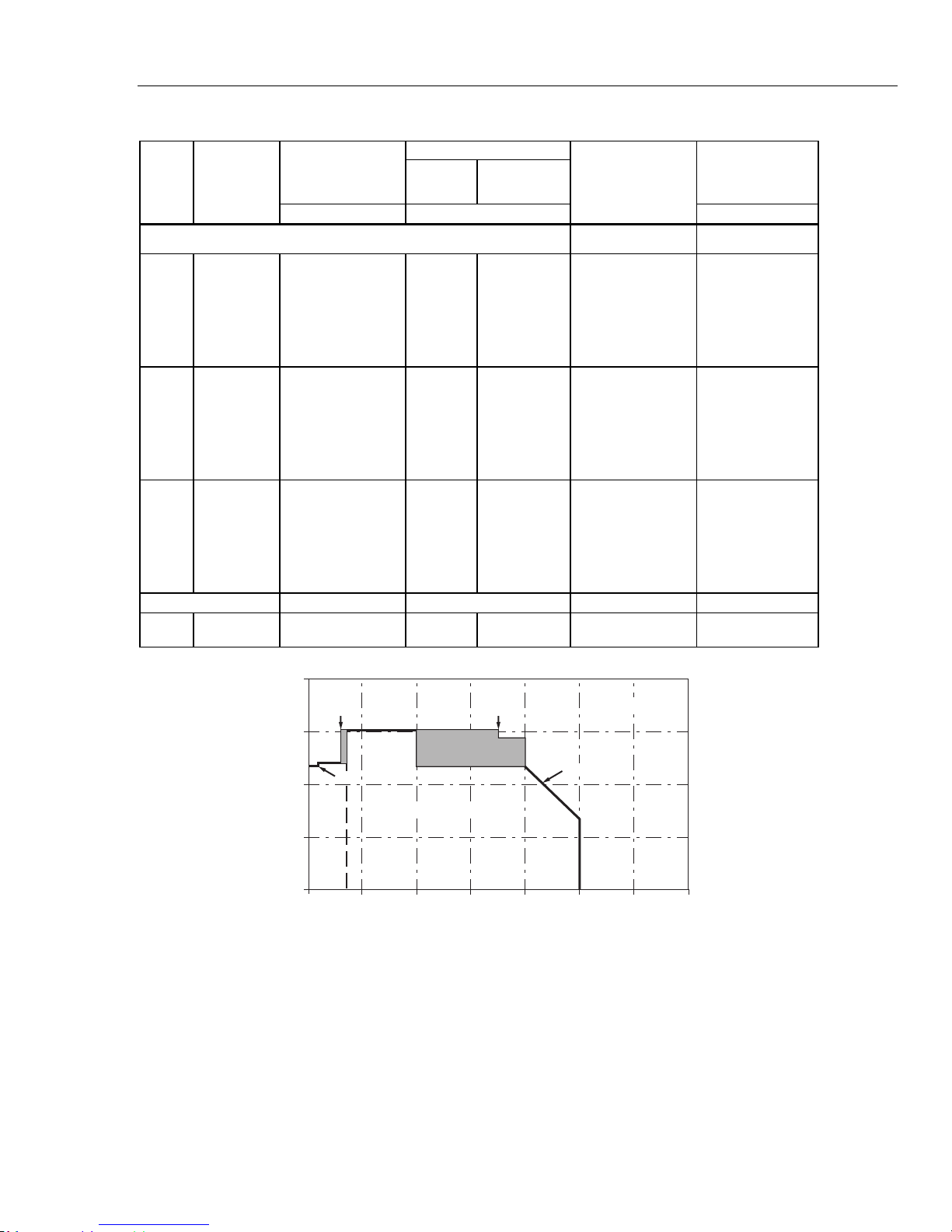
Multifunction Calibrator
Electrical Specifications
Temperature Coefficient
[1]
10 - 40 °C
0 - 10 °C and
40 - 50 °C
Output Impedance
(Ω)
Range
Frequency
(Hz)
Stability ±1 °C
24 Hours
±μV ±μV / °C ±(% output + μV)
Load Regulation
±(ppm output + μV)
10 + 2
10 + 2
10 + 4
30 + 10
120 + 16
300 ppm
600 ppm
1200 ppm
10 + 20
10 + 20
10 + 30
30 + 50
80 + 80
100 + 700
200 + 1100
600 + 3000
10 + 200
10 + 200
10 + 300
30 + .600
80 + 3,000
250 + 25,000
500 + 50,000
1000 + 110,000
10 + 2
10 + 1
2.2 V
22 V
220 V
1100 V
10 - 20
20 - 40
40 - 20 k
20 k - 50 k
50 k - 100 k
100 k - 300 k
300 k - 500 k
500 k - 1 M
10 - 20
20 - 40
40 - 20 k
20 k - 50 k
50 k - 100 k
100 k - 300 k
300 k - 500 k
500 k - 1 M
10 - 20
20 - 40
40 - 20 k
20 k - 50 k
50 k - 100 k
100 k - 300 k
300 k - 500 k
500 k - 1 M
15 - 50
50 - 1 k
150 + 20
80 + 15
12 + 4
15 + 5
15 + 5
30 + 10
70 + 20
150 + 50
150 + 20
80 + 15
12 + 8
15 + 10
15 + 10
30 + 15
70 + 100
150 + 100
150 + 200
80 + 150
12 + 80
15 + 100
15 + 100
30 + 400
100 + 10,000
200 + 20,000
50 + 10
15 + 5
2 + 1
10 + 2
10 + 4
80 + 15
80 + 40
80 + 100
50 + 100
15 + 30
2 + 10
10 + 20
10 + 40
80 + 150
80 + 300
80 + 500
50 + 1000
15 + 300
2 + 80
10 + 100
10 + 500
80 + 600
80 + 800
80 + 1000
50 + 10
15 + 5
5 + 2
15 + 4
20 + 4
80 + 15
80 + 40
80 + 100
50 + 100
15 + 40
4 + 15
20 + 20
20 + 40
80 + 150
80 + 300
80 + 500
50 + 1000
15 + 300
4 + 80
20 + 100
20 + 500
80 + 600
80 + 800
80 + 1000
±(ppm output + mV) ±(ppm outpu t) / °C ±(ppm output + mV) ±(% output)
150 + 0.5
20 + 0.5
50
2
50
5
Maximum
Distortion
Bandwidth 10 Hz-
10 MHz
0.05 + 80
0.035 + 80
0.035 + 80
0.035 + 80
0.035 + 110
0.3 + 110
0.5 + 110
1 + 110
0.05 + 700
0.035 + 700
0.035 + 700
0.035 + 700
0.05 + 800
0.3 + 800
0.3 + 800
2 + 800
0.05 + 10,000
0.05 + 10,000
0.05 + 10,000
0.05 + 10,000
0.2 + 50,000
1.5 + 50,000
1.5 + 50,000
3.5 + 100,000
0.15
0.07
10000
Voltage
1000
100
3.5 V
40 Hz 30 Hz
15 Hz
2.2 x 10⁷ V-Hz
Volt-Hertz Capability
10
0
50 Hz10 Hz 1 kHz 100 kHz 1 MHz 30 MHz
Frequency
Figure A.
29
Page 40
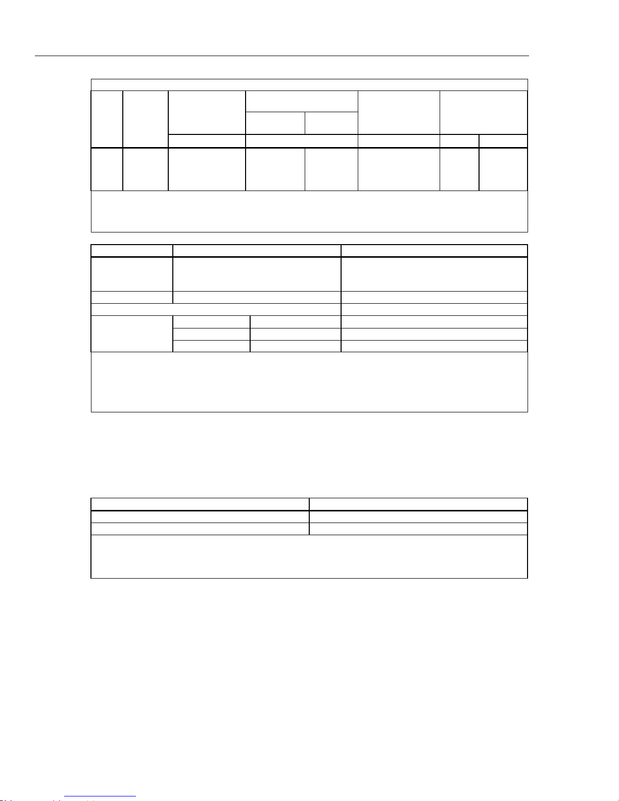
5730A
±
Getting Started Manual
5725A Amplifier:
Range
40 - 1 k
1100 V
Output Display Formats ....................................... Voltage or dBm, dBm reference 600 Ω.
Minimum Output ................................................... 10 % on each range
External Sense ...................................................... Applicable for 2.2 V, 22 V, 220 V, and 1100 V ranges; 5730A
1 k - 20 k
20 k - 50 k
50 k - 100 k
Notes:
1. Stability specifications are included in Absolute specification values for the primary specifications.
2. The 5725A will drive up to 1000 pF of load capacitance. Absolute specifications include loads to 300 pF and 150 pF as shown
under "Load Limits." For capacitances up to the maximum of 1000 pF, add "Load Regulation."
Voltage Range Maximum Current Limits Load Limits
2.2 V
220 V
1100 V 6 mA 600 pF
5725A Amplifier:
1100 V 5 kHz-30 kHz 70 mA 300 pF
Notes:
1. The 5725A will drive up to 1000 pF of load capacitance. Absolute specifications include loads to 300 pF and 150 pF as shown
under "Load Limits." For capacitances up to the maximum of 1000 pF, add "Load Regulation."
2. 2.2 V Range, 100 kHz-1.2 MHz only: Absolute specifications cover loads to 10 mA or 1000 pF. For higher loads, load regulation
is added.
3. Applies from 0 °C to 40 °C.
Temperature Coefficient
10 - 40 °C
Frequency
(Hz)
Stability
[1]
±1 °C
24 Hours
(ppm output + mV) ±(ppm output) / °C ±(ppm output + mV)
22 V
10 + .5
15 + 2
40 + 2
130 + 2
[2]
50 mA, 0 °C-40 °C
5
5
10
30
20 mA, 40 °C-50 °C
40 Hz-5 kHz 50 mA
30 kHz-100 kHz 70 mA
<100 kHz, 5725A <30 kHz. Specifications are the same as internal
sense.
Adder
0 - 10 °C and
40 - 50 °C
Load Regulation
[2]
10 Hz -10 MHz
Bandwidth
±(% output)
150 pF 1000 pF
Distortion
5
5
10
30
10 + 1
90 + 6
275 + 11
500 + 30
0.10
0.10
0.30
0.40
0.10
0.15
0.30
0.40
>50 Ω,
1000 pF
[1]
1000 pF
[3]
150 pF
30
Settling Time to Published Specifications
Frequency (Hz) Settling Time (seconds)
10-120 7
>120 5
Notes:
Plus 1 second for amplitude or frequency range change
Plus 2 seconds for 5730A 1100 V range
Plus 4 seconds for 5725A 1100 V range
Page 41
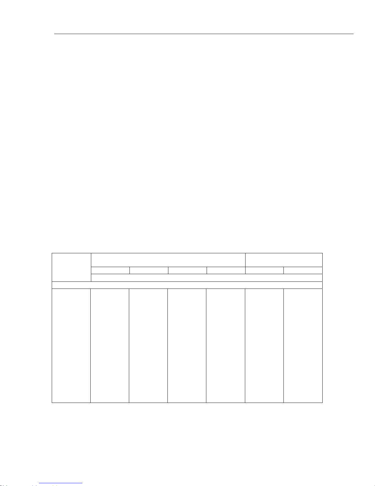
Multifunction Calibrator
Electrical Specifications
Overshoot .............................................................. <10 %
Common Mode Rejection
Frequency
Ranges (Hz) ........................................................ 10.000 - 119.99
Absolute Specification ........................................ ±0.0025 %
Resolution ........................................................... 11.999 counts
Phase Lock (Selectable Rear Panel BNC Input)
Phase Specification (except 1100 V range) ........ >30 Hz: ±1 ° + 0.05 °/kHz), <30 Hz: ±3 °
Input Voltage ....................................................... 1 V to 10 V rms sine wave (do not exceed 1 V for mV ranges)
Frequency Range ............................................... 10 Hz to 1.1999 MHz
Lock Range ......................................................... ±2 % of frequency
Lock-In Time ....................................................... Larger of 10/frequency or 10 msec
Phase Reference (Selectable Rear Panel BNC Output)
Range ................................................................. ±180 °
Phase Absolute Specification ............................. (except 1100 V range) ±1 ° at quadrature points (0 °, ±90 °, ±180 °)
Stability ............................................................... ±0.1 °
Resolution ........................................................... 1 °
Output Level ....................................................... 2.5 V rms ±0.2 V
Frequency Range ............................................... 50 Hz to 1 kHz, usable 10 Hz to 1.1999 MHz
....................................... 140 dB, dc to 400 Hz
0.1200 k - 1.1999 k
1.200 k - 11.999 k
12.00 k - 119.99 k
120.0 k - 1.1999 M
elsewhere ±2 °
Resistance Specifications
Absolute Specification of Characterized Value
Nominal Value
(Ω)
0
1
1.9
10
19
100
190
1 k
1.9 k
10 k
19 k
100 k
190 k
1 M
1.9 M
10 M
19 M
100 M
24 Hours 90 Days 180 Days 1 Year 24 Hours 90 Days
50 μΩ
85
85
23
23
10
10
13
15
33
43
100
±5 °C from calibration temperature
7
7
6
6
7
8
5730A Resistance Specifications
[1]
±ppm
99 % Confidence Level
50 μΩ
95
95
25
25
11
11
7.2
7.2
7
7
8
10
14
17
37
47
110
50 μΩ
100
100
26
26
11.5
11.5
7.5
7.5
7.5
7.5
9
11
14.5
19
40
50
115
50 μΩ
110
110
27
27
12
12
8
8
8
8
10
12
15
21
46
55
120
Relative ±1 °C
50 μΩ
32
25
5
4
2
2
2
2
2
2
2
2
2.5
3
10
20
50
50 μΩ
40
33
8
7
4
4
3
3
3
3
3
3
5
6
14
24
60
31
Page 42
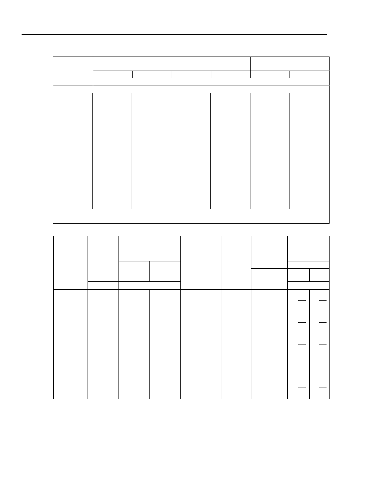
5730A
Getting Started Manual
Nominal Value
(Ω)
0
1
1.9
10
19
100
190
1 k
1.9 k
10 k
19 k
100 k
190 k
1 M
1.9 M
10 M
19 M
100 M
Note:
1. Specifications apply to displayed value. 4-wire connections, except 100 MΩ.
Absolute Specification of Characterized Value
±5 °C from calibration temperature
[1]
Relative ±1 °C
24 Hours 90 Days 180 Days 1 Year 24 Hours 90 Days
±ppm
95 % Confidence Level
40 μΩ
70
70
20
20
8
8
5.5
5.5
5
5
5.5
6
10
12
27
35
85
40 μΩ
80
80
21
21
9
9
5.7
5.7
5.5
5.5
7.5
7
11
13.5
31
39
95
40 μΩ
85
85
22
22
9.5
9.5
6
6
6
6
8
8
12
15
34
42
100
40 μΩ
95
95
23
23
10
10
6.5
6.5
6.5
6.5
8.5
8.5
13
18
40
47
100
40 μΩ
27
20
4
3.5
1.6
1.6
1.6
1.6
1.6
1.6
1.6
1.6
2
2.5
8
16
40
40 μΩ
35
26
7
6
3.5
3.5
2.5
2.5
2.5
2.5
2.5
2.5
4
4
12
20
50
Resistance Secondary Performance Specifications and Operating Ch aracteristics
Difference of
Characterized
to Nominal
Maximum
Value
±ppm
⎯
Compensation
Lead Resistance
Nominal
Value
(Ω)
Stability
[1]
±1 °C
24 Hours
Temperature Coefficient
10 - 40 °C
Adder
[2]
0 - 10 °C
and
40 - 50 °C
Full Spec Load
I
Range
- IU (mA)
L
[3]
Maximum
Peak
Current
I
MAX
(mA)
±ppm ±ppm/°C ±mΩ
0
⎯ ⎯ ⎯
8 - 500 500
1 32 4 5 8 - 100 700 500
1.9 25 6 7 8 - 100 500 500
10 5 2 3 8 - 11 220 300
19 4 2 3 8 - 11 160 300
Two-Wire
Adder Active
[4]
0.1 Ω 1 Ω
μV 4
2 +
4 +
I
m
μV 4
2 +
4 +
I
m
μV 4
2 +
4 +
I
m
μV 4
2 +
4 +
I
m
μV 4
2 +
4 +
I
m
μV 4
I
m
μV 4
I
m
μV 4
I
m
μV 4
I
m
μV 4
I
m
32
Page 43
Multifunction Calibrator
Electrical Specifications
Two-Wire
Adder Active
Compensation
[4]
Lead Resistance
0.1 Ω 1 Ω
Nominal
Value
(Ω)
Maximum
Stability
[1]
±1 °C
24 Hours
Temperature Coefficient
Adder
[2]
0 - 10 °C
10 - 40 °C
40 - 50 °C
and
Full Spec Load
I
Range
- IU (mA)
L
[3]
Maximum
Peak
Current
I
MAX
(mA)
Difference of
Characterized
to Nominal
Value
±ppm
±ppm ±ppm/°C ±mΩ
100 2 2 3 8 - 11 70 150
190 2 2 3 8 - 11 50 150
2 +
2 +
μV 4
I
m
μV 4
I
m
4 +
4 +
μV 4
I
m
μV 4
I
m
1 k 2 2 3 1 - 2 22 150 10 15
1.9 k 2 2 3 1 - 1.5 16 150
10 k 2 2 3
19 k 2 2 3
100 k 2 2 3
100 - 500 μA
50 - 250 μA
10 - 100 μA
7 150
5 150 100 120
1 150
10 15
50 60
I
= Current
m
produced by
Ohmmeter (A)
190 k
1 M
1.9 M
10 M
19 M
100 M
Notes:
1. Stability specifications are included in the Absolute specification values in the primary specification tables.
2. Temperature coefficient is an adder to Absolute specifications that does not apply unless operated more than 5 °C from calibration
temperature, or calibrated outside the range 19 °C to 24 °C. Two examples:
- Calibrate at 20 °C: Temperature coefficient adder is not required unless operated below 15 °C or above 25 °C.
- Calibrate at 26 °C: Add 2 °C temperature coefficient adder. Additional temperature coefficient adder is not required unless
operated below 21 °C or above 31 °C.
3. Refer to current derating factors table for loads outside of this range.
4. Active two-wire compensation may be selected for values less than 100 kΩ, with either the front panel or the meter input terminals
as reference plane. Active compensation is limited to 11 mA load, and to 2 V burden. Two-wire compensation can be used only
with Ω-meters that source continuous (not pulsed) dc current.
2 2 3
2.5 2.5 6
3.5 3 10
10 5 20
20 8 40
5 - 100 μA 500 μA
5 - 20 μA 100 μA
2.5 - 10 μA 50 μA
0.5 - 2 μA 10 μA
0.25 - 1 μA 5 μA
50 12 100 50 - 200 nA
1 μA
150
200
200
300
300
500
33
Page 44
5730A
Getting Started Manual
Nominal Value
Notes:
1. For I < I L, errors occur due to thermally generated voltages within the 5730A. Use the following equation to determine the error,
and add this error to the corresponding specifications.
Error = K(I
Where: Error is in mΩ for all two-wire comp values and four-wire short, and in ppm for the remaining four-wire values.
K is the constant from the above table;
I and IL are expressed in mA for short to 1.9 kΩ;
I and IL are expressed in μA for 10 kΩ to 100 MΩ
2. For I
in ppm and add this error to the corresponding specifications.
Error in ppm = K(I
Where: K is the constant from the above table;
I and I
I and I
(Ω)
Two-Wire Comp
SHORT
1
1.9
10
19
100
190
1 k
1.9 k
10 k
19 k
100 k
190 k
1 M
1.9 M
10 M
19 M
100 M
- I)/( I L x I)
L
< I < I
U
errors occur due to self-heating of the resistors in the calibrator. Use the following equation to determine the error
MAX
2
2
-I
)
U
are expressed in mA for short to 19 kΩ;
U
are expressed in μA for 100 kΩ to 100 MΩ
U
Current Derating Factors
Value of Derating Factor K for Over or Under Current
Four-Wire
[1]
I < IL
0.3
300
160
30
16
3.5
2.5
0.4
0.4
50
50
7.5
4.0
1.0
0.53
0.2
0.53
0.1
I < IL
4.4
4.4
4.4
4.4
4.4
4.4
4.4
4.4
4.4
5000
5000
⎯
⎯
⎯
⎯
⎯
⎯
[1]
Four-Wire
IU < I < IMAX
⎯
-5
4 x10
-4
1.5 x 10
-3
1.6 x 10
-3
3 x 10
-2
1 x 10
-2
1.9 x 10
0.1
0.19
2.0
3.8
-5
2 x 10
-5
3.8 x 10
-4
1.5 x 10
-4
2.9 x 10
-3
1 x 10
-3
1.9 x 10
⎯
[2]
34
Page 45
Multifunction Calibrator
Electrical Specifications
DC Current Specifications
5730A DC Current Specifications
Range
Resolution
nA
99 % Confidence Level
220 μA
2.2 mA
22 mA
220 mA
[1]
2.2 A
[1]
0.1
1
10
μA ±(ppm output + μA)
0.1
1
5725A Amplifier:
11 A 10 330 + 470 340 + 480 350 + 480 360 + 480 100 + 130 110 + 130
95 % Confidence Level
nA
220 μA
2.2 mA
22 mA
220 mA
[1]
2.2 A
[1]
0.1
1
10
μA ±(ppm output + μA)
0.1
1
5725A Amplifier:
11 A 10 330 + 470 340 + 480 350 + 480 360 + 480 100 + 130 110 + 130
Note:
Maximum output from the calibrator’s terminals is 2.2 A. Specifications for 220 μA and 2.2 mA ranges are increased by a factor of 1.3
when supplied through 5725A terminals.
Specifications are otherwise identical for all output locations.
1. Add to specifications:
±200 x I
±10 x I
2
ppm for >100 mA on 220 mA range
2
ppm for >1 A on 2.2 A range
Absolute / ±5 °C from calibration temperature Relative ±1 °C
24 Hours 90 Days 180 Days 1 Year 24 Hours 90 Days
±(ppm output + nA)
40 + 7
30 + 8
30 + 50
40 + 0.8
60 + 15
42 + 7
35 + 8
35 + 50
45 + 0.8
70 + 15
45 + 7
37 + 8
37 + 50
47 + 0.8
80 + 15
50 + 7
40 + 8
40 + 50
50 + 0.8
90 + 15
24 + 2
24 + 5
24 + 50
26 + 0.3
40 + 7
26 + 2
26 + 5
26 + 50
30 + 0.3
45 + 7
±(ppm output + nA)
32 + 6
25 + 7
25 + 40
35 + 0.7
50 + 12
35 + 6
30 + 7
30 + 40
40 + 0.7
60 + 12
37 + 6
33 + 7
33 + 40
42 + 0.7
70 + 12
40 + 6
35 + 7
35 + 40
45 + 0.7
80 + 12
20 + 1.6
20 + 4
20 + 40
22 + 0.25
32 + 6
22 + 1.6
22 + 4
22 + 40
25 + 0.25
40 + 6
35
Page 46
5730A
Getting Started Manual
DC Current Secondary Performance Specifications and Operating Characteristics
Range
220 μA
2.2 mA
22 mA
220 mA
2.2 A
5725A
11 A 25 + 100 20 + 75 30 + 120 4 0 4 15 + 70 175
Notes:
Maximum output from the calibrator’s terminals is 2.2 A. Specifications for 220 μA and 2.2 mA ranges are increased by a factor of 1.3
when supplied through 5725A terminals.
1. Stability specifications are included in the Absolute specification values for the primary specifications.
2. Temperature coefficient is an adder to Absolute specifications. It does not apply unless operating more than ±5 °C from
calibration temperature.
3. Burden voltage adder is an adder to Absolute specifications that does not apply unless burden voltage is greater than 0.5 V.
4. For higher loads, multiply Absolute specification by:
5. The calibrator’s compliance limit is 2 V for outputs from 1 A to 2.2 A. 5725A Amplifier may be used in range-lock mode down to
0 A.
Minimum Output .................................................. 0 for all ranges, including 5725A.
Settling Time ........................................................ 1 second for μA and mA ranges; 3 seconds for 2.2 A range; 6 seconds
Overshoot ............................................................. <5 %
Stability
[1]
±1 °C
24 Hours
±(ppm
output + nA)
5 + 1
5 + 5
5 + 50
8 + 300
9 + 7 μA
±(ppm
output + μA)
Temperature
Coefficient
[2]
0 - 10 °C
10 - 40 °C
and
40 - 50 °C
±(ppm output + nA) /
°C
1 + 0.40
1 + 2
1 + 20
1 + 200
1 + 2.5 μA
3 + 1
3 + 10
3 + 100
3 + 1 μA
3 + 10 μA
±(ppm output + μA)/
°C
Maximum
Compliance
Limits
10
10
10
10
[5]
3
Burden
Voltage
Adder
(±nA/V)
0.2
0.2
10
100
2 μA
Load for
Published
[3]
Specification
(Ω)
20k
200
[4]
2k
20
2
Bandwidth
0.1-10 Hz
pk-pk RMS
ppm output
+ nA
6 + .9
6 + 5
6 + 50
9 + 300
12 + 1.5 μA
ppm output
+ μA
1 +
load actualx 0.1
ionspecificat publishedfor load maximum
for 11 range; + 1 second for range or polarity change
Noise
Bandwidth
10 Hz-10 kHz
nA
10
10
50
500
20 μA
μA
36
Page 47
Multifunction Calibrator
Electrical Specifications
AC Current Specifications
5730A AC Current Specifications: 99 % Confidence Level
Range Resolution
220 μA
2.2 mA 10 nA
22 mA 100 nA
220 mA
2.2 A
11 A
Note:
Maximum output from the calibrator’s terminals is 2.2 A. Specifications for 220 μA and 2.2 mA ranges are increased by a factor of 1.3
plus 2 μA when supplied through 5725A terminals.
1 nA
1 μA
10 μA
100 μA
Frequency
(Hz)
10 - 20
20 - 40
40 - 1 k
1 k - 5 k
5 k - 10 k
10 - 20
20 - 40
40 - 1 k
1 k - 5 k
5 k - 10 k
10 - 20
20 - 40
40 - 1 k
1 k - 5 k
5 k - 10 k
10 - 20
20 - 40
40 - 1 k
1 k - 5 k
5 k - 10 k
20 - 1 k
1 k - 5 k
5 k - 10 k
40 - 1 k
1 k - 5 k
5 k - 10 k
Absolute / ±5 °C from calibration temperature Relative ±1 °C
24 Hours 90 Days 180 Days 1 Year 24 Hours 90 Days
±(ppm output + nA)
260 + 20
170 + 12
115 + 10
300 + 15
1000 + 80
260 + 50
170 + 40
115 + 40
210 + 130
1000 + 800
260 + 500
170 + 400
115 + 400
210 + 700
1000 + 6000
260 + 5
170 + 4
115 + 3
210 + 4
1000 + 12
270 + 40
440 + 100
6000 + 200
5725A Amplifier:
370 + 170
800 + 380
3000 + 750
280 + 20
180 + 12
117 + 10
320 + 15
1100 + 80
280 + 50
180 + 40
117 + 40
220 + 130
1100 + 800
280 + 500
180 + 400
117 + 400
220 + 700
1100 + 6000
280 + 5
180 + 4
117 + 3
220 + 4
1100 + 12
280 + 40
460 + 100
7000 + 200
400 + 170
850 + 380
3300 + 750
290 + 20
190 + 12
118 + 10
340 + 15
1200 + 80
290 + 50
190 + 40
118 + 40
230 + 130
1200 + 800
290 + 500
190 + 400
118 + 400
230 + 700
1200 + 6000
±(ppm output + μA)
290 + 5
190 + 4
118 + 3
230 + 4
1200 + 12
290 + 40
480 + 100
7500 + 200
440 + 170
900 + 380
3500 + 750
300 + 20
200 + 12
120 + 10
350 + 15
1300 + 80
300 + 50
200 + 40
120 + 40
240 + 130
1300 + 800
300 + 500
200 + 400
120 + 400
240 + 700
1300 + 6000
1300 + 12
300 + 40
500 + 100
8000 + 200
460 + 170
950 + 380
3600 + 750
300 + 5
200 + 4
120 + 3
240 + 4
260 + 20
130 + 12
100 + 10
250 + 15
900 + 80
260 + 50
130 + 40
100 + 40
190 + 130
900 + 800
260 + 500
130 + 400
100 + 400
190 + 700
900 + 6000
260 + 5
130 + 4
100 + 3
190 + 4
900 + 12
260 + 40
420 + 100
6000 + 200
300 + 170
700 + 380
2800 + 750
280 + 20
150 + 12
110 + 10
280 + 15
1000 + 80
280 + 50
150 + 40
110 + 40
220 + 130
1000 + 800
280 + 500
150 + 400
110 + 400
220 + 700
1000 +
6000
280 + 5
150 + 4
110 + 3
220 + 4
1000 + 12
280 + 40
440 + 100
7000 + 200
330 + 170
800 + 380
3200 + 750
37
Page 48
5730A
Getting Started Manual
Range Resolution
220 μA
2.2 mA 10 nA
22 mA 100 nA
220 mA
2.2 A
5725A Amplifier:
11 A
Note:
Maximum output from the calibrator’s terminals is 2.2 A. Specifications for 220 μA and 2.2 mA ranges are increased by 1.3 plus 2 μA
when supplied through 5725A terminals.
5730A AC Current Specifications: 95 % Confidence Level
Absolute / ±5 °C from calibration temperature Relative ±1 °C
24 Hours 90 Days 180 Days 1 Year 24 Hours 90 Days
±(ppm output + nA)
210 + 16
130 + 10
96 + 8
240 + 12
800 + 65
210 + 40
130 + 35
96 + 35
170 + 110
800 + 650
210 + 400
130 + 350
96 + 350
170 + 550
800 + 5000
210 + 4
130 + 3.5
96 + 2.5
170 + 3.5
800 + 10
214 + 35
350 + 80
5000 + 160
370 + 170
800 + 380
3000 + 750
230 + 16
140 + 10
99 + 8
250 + 12
900 + 65
230 + 40
140 + 35
99 + 35
180 + 110
900 + 650
230 + 400
140 + 350
99 + 350
180 + 550
900 + 5000
230 + 4
140 + 3.5
99 + 2.5
180 + 3.5
900 + 10
224 + 35
390 + 80
6000 + 160
400 + 170
850 + 380
3300 + 750
240 + 16
150 + 10
101 + 8
270 + 12
1000 + 65
240 + 40
150 + 35
101 + 35
190 + 110
1000 + 650
240 + 400
150 + 350
101 + 350
190 + 550
1000 + 5000
±(ppm output + μA)
240 + 4
150 + 3.5
101 + 2.5
190 + 3.5
1000 + 10
234 + 35
420 + 80
6500 + 160
440 + 170
900 + 380
3500 + 750
1100 + 5000
7000 + 160
3600 + 750
1 nA
1 μA
10 μA
100 μA
Frequency
(Hz)
10 - 20
20 - 40
40 - 1 k
1 k - 5 k
5 k - 10 k
10 - 20
20 - 40
40 - 1 k
1 k - 5 k
5 k - 10 k
10 - 20
20 - 40
40 - 1 k
1 k - 5 k
5 k - 10 k
10 - 20
20 - 40
40 - 1 k
1 k - 5 k
5 k - 10 k
20 - 1 k
1 k - 5 k
5 k - 10 k
40 - 1 k
1 k - 5 k
5 k - 10 k
250 + 16
160 + 10
103 + 8
280 + 12
1100 + 65
250 + 40
160 + 35
103 + 35
200 + 110
1100 + 650
250 + 400
160 + 350
103 + 350
200 + 550
250 + 4
160 + 3.5
103 + 2.5
200 + 3.5
1100 + 10
244 + 35
450 + 80
460 + 170
950 + 380
210 + 16
110 + 10
80 + 8
200 + 12
700 + 65
210 + 40
110 + 35
80 + 35
160 + 110
700 + 650
210 + 400
110 + 350
80 + 350
160 + 550
700 + 5000
210 + 4
110 + 3.5
80 + 2.5
160 + 3.5
700 + 10
200 + 35
300 + 80
5000 + 160
300 + 170
700 + 380
2800 + 750
230 + 16
130 + 10
90 + 8
230 + 12
800 + 65
230 + 40
130 + 35
90 + 35
170 + 110
800 + 650
230 + 400
130 + 350
90 + 350
170 + 550
800 + 5000
230 + 4
130 + 3.5
90 + 2.5
170 + 3.5
800 + 10
230 + 35
350 + 80
6000 +
160
330 + 170
800 + 38
3200 +
750
38
Page 49
Multifunction Calibrator
Electrical Specifications
AC Current Secondary Performance Specifications and Operating Characteristics
Noise and
Distortion
(Bandwidth
10 Hz - 50 kHz
<0.5V Burden)
0.05 + 0.1
0.05 + 0.1
0.05 + 0.1
0.25 + 0.5
00.5 + 1
0.05 + 0.1
0.05 + 0.1
0.05 + 0.1
0.25 + 0.5
00.5 + 1
0.05 + 0.1
0.05 + 0.1
0.05 + 0.1
0.25 + 0.5
00.5 + 1
0.05 + 10
0.05 + 10
0.05 + 10
0.25 + 50
00.5 + 100
0.5 + 100
0.3 + 500
1 + 1 mA
±(% output)
[5]
0.05
[5]
0.12
[5]
0.5
Range
220 μA
2.2 mA
22 mA
220 mA
2.2 A
Frequency
(Hz)
10 - 20
20 - 40
40 - 1 k
1 k - 5 k
5 k - 10 k
10 - 20
20 - 40
40 - 1 k
1 k - 5 k
5 k - 10 k
10 - 20
20 - 40
40 - 1 k
1 k - 5 k
5 k - 10 k
Hz
10 - 20
20 - 40
40 - 1 k
1 k - 5 k
5 k - 10 k
20 - 1 k
1 k - 5 k
5 k - 10 k
Stability ±1 °C
24 Hours
±(ppm output +
nA)
150 + 5
80 + 5
30 + 3
50 + 20
400 + 100
150 + 5
80 + 5
30 + 3
50 + 20
400 + 100
150 + 50
80 + 50
30 + 30
50 + 500
400 + 1000
±(ppm output +
μA)
150 + 0.5
80 + 0.5
30 + 0.3
50 + 3
400 + 5
50 + 5
80 + 20
800 + 50
[1]
Temperature
Coefficient
10 - 40 °C
[2]
0 - 10 °C and
40 - 50 °C
Compliance
Limits
(V rms)
±(ppm output + nA)/ °C ±(% output + μA)
50 + 5
20 + 5
4 + 0.5
10 + 1
20 + 100
50 + 5
20 + 4
4 + 1
10 + 100
50 + 400
50 + 10
20 + 10
4 + 10
10 + 500
50 + 1000
±(ppm output + μA)/°C
50 + 0.05
20 + 0.05
4 + 0.1
10 + 2
50 + 5
4 + 1
10 + 5
50 + 10
50 + 5
20 + 5
10 + 0.5
20 + 1
20 + 100
50 + 5
20 + 4
10 + 2
20 + 100
50 + 400
50 + 10
20 + 10
10 + 20
20 + 400
50 + 1000
50 + 0.05
20 + 0.05
10 + 0.1
20 + 2
50 + 5
10 + 1
20 + 5
50 + 10
7 2 k
7 800
7 80
7 8
1.4
Maximum
Resistive
Load
For
Published
Specification
[3]
(Ω)
[4]
0.8
5725A Amplifier:
40 - 1 k
11 A
1 k - 5 k
5 k - 10 k
Notes:
Maximum output from 5730A terminals is 2.2 A. Specifications for 220 μA and 2.2 mA ranges are increased by a factor of 1.3, plus
2 μA when supplied through 5725A terminals. Specifications are otherwise identical for all output locations.
1. Stability specifications are included in the Absolute values for the primary specifications.
2. Temperature coefficient is an adder to specifications that does not apply unless operating more than ±5 °C from calibration
temperature.
3. For larger resistive loads multiply accuracy specifications by: (
4. 1.5 V compliance limit above 1 A. 5725A Amplifier may be used in range-lock mode down to 1 A.
5. For resistive loads within rated compliance voltage limits.
75 + 100
100 + 150
200 + 300
20 + 75
40 + 75
100 + 75
30 + 75
50 + 75
100 + 75
3 3
load actual
)2
ionspecificat publishedfor load maximum
39
Page 50
5730A
Getting Started Manual
Minimum Output .................................................... 9 μA for 220 μA range, 10 % on all other ranges. 1 A minimum for
Inductive Load Limits ........................................... 400
Power Factors ........................................................ 5730A, 0.9 to 1; 5725A, 0.1 to 1. Subject to compliance voltage
Frequency
Range (Hz) .......................................................... 10.000 - 11.999, 12.00 - 119.99, 120.0 - 1199.9, 1.200 k - 10.000 k
Specification .................................................. ±0.01 % of output
Resolution ..................................................... 11,999 counts
Settling Time ...................................................... 5 seconds for 5730A ranges; 6 seconds for 5725A 11 A range; +1
Overshoot .......................................................... <10 %
Wideband AC Voltage (Option 5730A/03 and 5730A/05) Specifications (99 %
Confidence Level)
Specifications apply to the end of the cable and 50 Ω termination used for calibration.
Volts dBm
1.1 mV -46 10 nV 0.4 + 0.4 0.5 + 0.4 0.6 + 0.4 0.8 + 2
3.3 mV -37 10 nV 0.4 + 1 0.45 + 1 0.5 + 1 0.7 + 3
11 mV -26 100 nV 0.2 + 4 0.35 + 4 0.5 + 4 0.7 + 8
33 mV -17 100 nV 0.2 + 10 0.3 + 10 0.45 + 10 0.6 + 16
110 mV -6.2
330 mV +3.4
1.1 V +14
3.5 V +24
5725A.
μH (5730A, or 5725A). 20 μH for 5730A output >1 A.
limits.
second for amplitude or frequency range change.
Range
Resolution
1 μV
1 μV
10 μV
10 μV
Absolute / ±5 °C from calibration temperature
30 Hz - 500 kHz
24 Hours 90 Days 180 Days 1 Year
±(% output + μV)
0.2 + 40 0.3 + 40 0.45 + 40 0.6 + 40
0.2 + 100 0.25 + 100 0.35 + 100 0.5 + 100
0.2 + 400 0.25 + 400 0.35 + 400 0.5 + 400
0.15 + 500 0.2 + 500 0.3 + 500 0.4 + 500
Amplitude Flatness, 1 kHz Reference
Voltage Range
1.1 mV 3.3 mV >3.3 mV
±(% output + floor indicated)
0.2 + 3 μV 0.1 + 3 μV 0.1 + 3 μV
0.2 + 3 μV 0.1 + 3 μV 0.1 + 3 μV
0.4 + 3 μV 0.3 + 3 μV 0.2 + 3 μV
0.6 + 3 μV 0.5 + 3 μV 0.4 + 3 μV
1.5 + 15 μV 1.5 + 3 μV 1 + 3 μV
3.0 + 15 μV 3.0 + 3 μV 2.0 + 3 μV
[1]
[2]
Frequency
Resolution
(Hz)
1 k
10 k
Frequency
(Hz)
10 - 30 0.01 0.3 0.3 0.3 100 7 -40
30 - 119.99 0.01 0.1 0.1 0.1 100 7 -40
120 - 1.1999 k 0.1 0.1 0.1 0.1 100 5 -40
1.2 k - 11.999 k 1 0.1 0.1 0.1 100 5 -40
12 k - 119.99 k 10 0.1 0.1 0.1 100 5 -40
120 k - 1.1999 M 100
1.2 M - 2 M
2 M - 11.9 M 1 k
12 M - 20 M 10 k
20 M - 30 M 10 k
30 M - 50 M
Note:
1. For output voltages <50 % of full range in the 33 mV, 110 mV, 330 mV, 1.1 V , and 3.5 V ranges, add 0.1 % to the amplitude
flatness specification.
Temperature
Coefficient
±ppm/°C
100 5 -40
100 0.5 -40
100 0.5 -40
150 0.5 -34
300 0.5 -34
600 0.5 -34
Settling Time
To Published
Specification
(Seconds)
Harmonic
Distortion
Additional Operating Information:
dBm reference = 50 Ω
Range boundaries are at voltage points, dBm levels are approximate.
dBm = 10 log (
2. Applies to Option 5730A/05 only.
Power
) ; 0.22361 V across 50 Ω = 1 mW or 0 dBm
mW 1
(dB)
40
Page 51

Multifunction Calibrator
Electrical Specifications
Minimum Output ................................................... 300 μV (-57 dBm)
VSWR at Output Terminal .................................... <1.1 Typical
Frequency Specification ...................................... ±0.01 % of output
Frequency Resolution .......................................... 11,999 counts to 1.1999 MHz, 10799 counts to 11.999 MHz, 3800
Overload Protection .............................................. A short circuit on the wideband output will not result in damage. After
counts to 50 MHz
settling time, normal operation is restored upon removal.
52120A Specifications when Operated with the 5730A
Line Power
Voltage range ..................................................... 100 V to 240 V
Frequency ........................................................... 47 to 63 Hz
Voltage variations ............................................... ±10 % about line voltage
Power consumption ............................................ <1500 VA
Dimensions (HxWxL)
With feet .............................................................. 192 mm x 432 mm x 645 mm (7.6 in x 17.0 in x 25.5 in)
Without feet ......................................................... 178 mm x 432 mm x 645 mm (7.0 in x 17.0 in x 25.5 in)
Weight .................................................................... 25 kg (54 lb)
Temperature
Operating ............................................................ 5 °C to 35 °C (41 °F to 95 °F)
Calibration (tcal) .................................................. 16 °C to 30 °C (61 °F to 86 °F)
Storage ............................................................... 0 °C to 50 °C (32 °F to 122 °F)
Transit ................................................................. -20 °C to +60 °C (-4 °F to +140 °F) <100 hours
Warmup Time ........................................................ Twice the time since last warmed up, to a maximum of 1 hour.
Humidity (non-condensing)
Operating ............................................................ <80 %, 5 °C to 31 °C (41 °F to 88 °F) ramping linearly down to 50 % at
Storage ............................................................... <95 %, 0 to 50 °C (32 °F to 122 °F)
Altitude
Operating ............................................................ 2,500 m (8,200 ft) maximum
Non-Operating .................................................... 12,000 m (39,400 ft) maximum
Shock and Vibration ............................................. MIL-PRF-28800F Class 3
Safety ..................................................................... EN/IEC 61010-1, 300 V CAT II, Pollution Degree 2
Electromagnetic Environment ............................. IEC 61326-1, Industrial
Electromagnetic Compatibility ............................ FCC Rules part 15 sub part B
Indoor use only ..................................................... IP20
35 °C (95 °F)
Applies to use in Korea only. Class A Equipment (Industrial
Broadcasting & Communication Equipment)
[1] This product meets requirements for industrial (Class A)
electromagnetic wave equipment and the seller or user should
take notice of it. This equipment is intended for use in business
environments and is not to be used in homes.
[1]
41
Page 52
5730A
Getting Started Manual
52120A Electrical Performance Limits
Voltage compliance developed across inductive loads may prevent range maximum current output being achieved at
higher frequencies. The appropriate maximum frequency (Fmax) for a given load inductance and current is given by:
The maximum frequency calculated with this equation is only approximate. Series resistance and parallel capacitance
also affect the maximum achievable frequency.
Input Common Mode Rejection ........................... 80 dB @ DC decreasing linearly to 40 dB at 10 kHz
Input Impedance
Voltage input ....................................................... >1 MΩ
Current input ....................................................... 10 Ω
Maximum Output Compliance Voltage ............... 4.5 V rms (6.4 V pk), 6.4 V dc. 120 A range maximum compliance
DC Offset ............................................................... Magnetic remanence that follows abrupt changes in output current
Operated within 5730A Control Loop (all current ranges)
The current specification of the 52120A, when controlled by a single 5730A, applies to the parallel output of up to three
52120As connected as slaves.
4.5 I = Current
Fmax =
2
•π•I•L
L = Total
inductance
voltage decreases from 4.5 V at 1 kHz to about 3 V at 10 kHz
level may cause small changes to DC current offset. It is good practice
to correct for offsets in DC measurements and techniques such as DC
reversal measurement will result in best accuracy.
Coverage factor k=2.58 (99 % confidence level)
Current Specification
[1]
1-year, tcal
Frequency
% of output % of range
DC 0.015 0.010
10 Hz to 850 Hz 0.011 0.003
850 Hz to 6 kHz 0.052 0.005
6 kHz to 10 kHz See Operated Stand Alone current specification table in the 52120A Users Manual.
Notes:
1. tcal is the temperature at which calibration adjustment took place.
Maximum inductance for stability LCOMP OFF is 100 μH. Maximum inductance for stability LCOMP ON is 400 μH for 2 A and 20 A
ranges. 100 μH on the 120 A range.
With LCOMP ON, the output is limited to 7.2e3 A-Hz. For example, a 100 A output is limited to 72 Hz.
±5 °C ±(% of output + % of range)
5730A
42
Page 53
Multifunction Calibrator
Electrical Specifications
Coverage factor k=2.00 (95 % confidence level)
Current Specification
1-year, tcal
Frequency
% of output % of range
DC 0.012 0.008
10 Hz to 850 Hz 0.009 0.002
850 Hz to 6 kHz 0.040 0.004
6 kHz to 10 kHz See Operated Stand Alone current specification table in the 52120A Users Manual.
Notes:
1. tcal is the temperature at which calibration adjustment took place.
Maximum inductance for stability LCOMP OFF is 100 μH. Maximum inductance for stability LCOMP ON is 400 μH for 2 A and 20 A
ranges. 100 μH on the 120 A range.
With LCOMP ON, the output is limited to 7.2e3 A-Hz. For example, a 100 A output is limited to 72 Hz.
Maximum Distortion and Noise
Frequency
2 Amp Range
16 Hz to 850 Hz
850 Hz to 6 kHz
6 kHz to 10 kHz
[2]
20 Amp Range
16 Hz to 850 Hz
850 Hz to 6 kHz -52 6.6 mA -42 20.9 mA -70 dB
6 kHz to 10 kHz
[2]
120 Amp Range
16 Hz to 850 Hz -76 2.5 mA -60 15.8 mA -70 dB
850 Hz to 6 kHz -52 39.7 mA -42 125.7 mA -70 dB
6 kHz to 10 kHz
Notes:
1. Use dB or Current. Whichever is larger.
2. Interharmonics only above 6 kHz.
[2]
LCOMP OFF LCOMP ON
dBc Current dBc Current
-76
-52
42 μA
662 μA
-40 2.6 mA -35 4.7 mA -60 dB
-76
418 μA
-40 26.4 mA -35 46.9 mA -70 dB
-40 158.2 ma -35 281.3 mA -70 dB
[1]
±5 °C ±(% of output + % of range)
5730A
Distortion
[1]
-70
-46 1.3 mA -60 dB
-60 2.6 mA -70 dB
83 μA
Noise
16 Hz to 10 MHz
-60 dB
43
Page 54
5730A
Getting Started Manual
52120A/COIL 3 kA 25-Turn Coil
Number of Turns ................................................... 25
Minimum internal jaw dimension to clear wires 26 mm (width) x 36 mm (length)
Maximum Input Current ........................................ 120 A continuous with built-in 12 V fan on
Maximum Voltage ................................................. 4.5 V rms
Input Current
0 A to 100 A DC 0 to 2500 0.7 % 0.7 %
0 A to 120 A 10 Hz to 65 Hz 0 to 3000 0.7 % 0.7 %
0 A to 120 A 65 Hz to 300 Hz 0 to 3000 0.7 % 0.7 %
0 A to 40 A 300 Hz to 1 kHz 0 to 1000 0.7 % 0.7 %
0 A to 12 A 1 kHz to 3 kHz 0 to 300 0.8 % 1.0 %
0 A to 3 A 3 kHz to 6 kHz 0 to 75 1.5 % 1.0 %
0 A to 1 A 6 kHz to 10 kHz 0 to 25 5.0 % 1.0 %
Notes:
1. The inductance and mutual inductance of the 25 turn coil and clamp that is measured causes a frequency dependent compliance
voltage across the coil. The length and configuration of the cables that connect the current to the coil also have an effect.
Maximum input current is 120 A input at approximately 100 Hz. Maximum current input decreases to approximately 0.8 A at
10 kHz.
2. Includes coil/clamp interaction.
Specification
[2]
[1]
Frequency
Effective Current
Amp-turns
52120A + Coil Specification
±(% of Amp-turns + % of 52120A range)
% of Amp-turns % of 52120A Range
52120A/COIL 6 kA 50-Turn Coil
Number of Turns ................................................... 50
Minimum Flexible Probe Length .......................... 500 mm
Maximum Input Current ........................................ 120 A continuous with built-in 12 V fan on
Maximum Voltage ................................................. 4.5 V rms
Specification
Input Current
[1]
Frequency
Effective Current
Amp-turns
0 A to 100 A DC 0 to 5000 0.7 % 0.7 %
0 A to 120 A 10 Hz to 65 Hz 0 to 6000 0.7 % 0.7 %
0 A to 120 A 65 Hz to 300 Hz 0 to 6000 0.7 % 0.7 %
0 A to 120 A 300 Hz to 1 kHz 0 to 6000 0.7 % 0.7 %
0 A to 120 A 1 kHz to 3 kHz 0 to 6000 0.8 % 1.0 %
0 A to 25 A 3 kHz to 6 kHz 0 to 1250 1.5 % 1.0 %
0 A to 13 A 6 kHz to 10 kHz 0 to 650 5.0 % 1.0 %
Notes:
1. The inductance and mutual inductance of the 50 turn coil causes a frequency dependent compliance voltage across the coil.
Maximum frequency for 120 A input current is approximately 600 Hz. Maximum current input decreases to approximately 13 A at
10 kHz.
2. Includes coil/probe interaction.
52120A + Coil Specification
±(% of Amp-turns + % of 52120A range)
% of Amp-turns % of 52120A Range
[2]
44
Page 55
Multifunction Calibrator
Electrical Specifications
Note
The specifications for these coils are at 99 % confidence level and are the combined
specification of the coil and a 52120A. If the coils are used with other current
sources the calibration specification of the coils alone is 0.65 % (99 % confidence
level) from 0 Hz to 10 kHz.
Operating Limits
Current Output (Max.) 2 A rms 20 A rms 120 A rms
Current Input
Input Current (Max.) 200 mA rms 200 mA rms 120 mA rms
Current gain 10 100 1,000
Voltage Input
Input Voltage (Max.) 2 V rms 2 V rms 1.2 V rms
Transconductance 1 Siemen 10 Siemens 100 Siemens
2 A 20 A 120 A
Output Current Range
120 A Range Current/Frequency Limits
Frequency Maximum Output Current Maximum Current Input Maximum Voltage Input
DC
<10 Hz 100 A pk (70 A rms) 100 mA pk (70 mA rms) 1.0 V pk (0.7 V rms)
10 Hz to 10 kHz 170 A pk (120 A rms) 170 mA pk (120 mA rms) 1.7 V pk (1.2 V rms)
Note:
The 2 A and 20 A ranges operate at full output current from DC to 10 kHz.
±100 A ±100 mA ±1.0 V
Output Isolation
Frequency Maximum Voltage Signal Applied to any Output Current Terminal with respect to Earth
DC to 850 Hz 600 V rms, 850 V pk, limited 2 A rms, no transient overvoltages
850 Hz to 3 kHz 100 V rms, 142 V pk, limited 2 A rms, no transient overvoltages
3 kHz to 10 kHz 33 V rms, 47 V pk, limited 2 A rms, no transient overvoltages
45
Page 56

5730A
Getting Started Manual
46
 Loading...