

Page 1

5700A/5720A Series II
®
Multi-Function Calibrator
Getting Started
PN 1668111
March 2002
© 2002 Fluke Corporation, All rights reserved. Printed in USA
All product names are trademarks of thei r r espective c omp ani es.
Page 2

LIMITED WARRANTY & LIMITATION OF LIABILITY
Each Fluke product is warranted to be free from defects in material and workmanship
under normal use and service. The warranty period is one year and begins on the date
of shipment. Parts, product repairs and services are warranted for 90 days. This
warranty extends only to the original buyer or end-user customer of a Fluke authorized
reseller, and does not apply to fuses, disposable batteries or to any product which, in
Fluke’s opinion, has been misused, altered, neglected or damaged by accident or
abnormal conditions of operation or handling. Fluke warrants that software will operate
substantially in accordance with its functional specifications for 90 days and that it has
been properly recorded on non-defective media. Fluke does not warrant that software
will be error free or operate without interruption.
Fluke authorized resellers shall extend this warranty on new and unused products to
end-user customers only but have no authority to extend a greater or different warranty
on behalf of Fluke. Warranty support is available if product is purchased through a Fluke
authorized sales outlet or Buyer has paid the applicable international price. Fluke
reserves the right to invoice Buyer for importation costs of repair/replacement parts
when product purchased in one country is submitted for repair in another country.
Fluke’s warranty obligation is limited, at Fluke’s option, to refund of the purchase price,
free of charge repair, or replacement of a defective product which is returned to a Fluke
authorized service center within the warranty period.
To obtain warranty service, contact your nearest Fluke authorized service center or send
the product, with a description of the difficulty, postage and insurance prepaid (FOB
Destination), to the nearest Fluke authorized service center. Fluke assumes no risk for
damage in transit. Following warranty repair, the product will be returned to Buyer,
transportation prepaid (FOB Destination). If Fluke determines that the failure was
caused by misuse, alteration, accident or abnormal condition of operation or handling,
Fluke will provide an estimate of repair costs and obtain authorization before
commencing the work. Following repair, the product will be returned to the Buyer
transportation prepaid and the Buyer will be billed for the repair and return transportation
charges (FOB Shipping Point).
THIS WARRANTY IS BUYER’S SOLE AND EXCLUSIVE REMEDY AND IS IN LIEU OF
ALL OTHER WARRANTIES, EXPRESS OR IMPLIED, INCLUDING BUT NOT LIMI TED
TO ANY IMPLIED WARRANTY OF MERCHANTABILITY OR FITNESS FOR A
PARTICULAR PURPOSE. FLUKE SHALL NOT BE LIABLE FOR ANY SPECIAL,
INDIRECT, INCIDENTAL OR CONSEQUENTIAL DAMAGES O R LOSSES, INCLUDING
LOSS OF DATA, WHETHER ARISING FROM BREACH OF WARRANTY OR BASED
ON CONTRACT, TORT, RELIANCE OR ANY OTHER THEORY.
Since some countries or states do not allow limitation of the term of an implied warranty,
or exclusion or limitation of incidental or consequential damages, the limitations and
exclusions of this warranty may not apply to every buyer. If any provision of this
Warranty is held invalid or unenforceable by a court of competent jurisdiction, such
holding will not affect the validity or enforceability of any other provision.
Fluke Corporation Fluke Europe B.V.
P.O. Box 9090 P.O. Box 1186
Everett, WA 98206-9090 5602 BD Eindhoven
U.S.A. The Netherlands
5/94
Page 3

Claims
Immediately upon arrival, purchaser shall check the packing container against the enclosed
packing list and shall, within thirty (30) days of arrival, give Fluke notice of shortages or any
nonconformity with the terms of the order. If purchaser fails to five notice, the delivery shall be
deemed to conform with the terms of the order.
The purchaser assumes all risk of loss or damage to instruments upon delivery by Fluke to the
carrier. If an instrument is damaged in transit, PURCHASER MUST FILE ALL CLAIMS FOR
DAMAGE WITH THE CARRIER to obtain compensation. Upon request by purcha ser, Fluke will
submit an estimate of the cost to repair shipment damage.
Fluke will be happy to answer all questions to enhance the use of this instrument. Please address
your requests or correspondence to: Fluke Corporation, P.O. Box 9090, Everett, WA 98206-9090.
Declaration of the Manufacturer or Importer
We hereby certify that the Fluke Models 5700A Series II and 5720A Series II are in compliance
with Postal Regulation Vfg. 1046 and is RFI suppressed. The marketing and sale of the
equipment was reported to the German Postal Service. The right to retest this equipment to verify
compliance with the regulation was given to the German Postal Service.
Bescheinigung des Herstellers/Importeurs
Hiermit wird bescheinigt, daβ Fluke Models 5700A Series II und 5720A Series II in
Übereinstimung mit den Bestimmungen der Amtsblattverfügung Vfg. 1046 funk-entstört ist, Der
Deutschen Bundespost wurde das Inverkehrbringen dieses Gerätes angezeigt und die
Berechtigung zur Überpr üf ung der Seir e auf Einh alt un g der Be st imm ung en eingeräumt.
Fluke Corporation
Interference Information
This equipment generates and use s radio frequ en cy energy and if not installed and used in strict
accordance with the manufacturer’s instructions, may cause interference to radio and television
reception. It has been type tested and found to comply with the limits for a Class B computing
device in accordance with the specifications in Subpart J of Part 15 of FCC Rules, which are
designed to provide reasona bl e protec tio n agai ns t su ch inter f eren ce in a res id ent ial in st al lati on.
However, there is no guarantee that interference will not occur in a particular installation. If this
equipment does cause interference to radio or television reception, which can be determined by
turning the equipment off and on, the user is encouraged to try to correct the interference by one
of more of the following measures:
Reorient the receiving antenna
•
• Relocate the equipment with respect to the receiver
• Move the equipment away from the receiver
• Plug the equipment into a different outlet so that the computer and receiver are on dif ferent
branch circuits
If necessary, the user should consult the dealer or an experienced radio/television technician for
additional suggestions. The user may find the following booklet prepared by the Federal
Communications Commission helpful: How to Identify and Resolve Radio-TV Interference
Problems. This booklet is available from the U.S. Government Printing Office, Washington, D.C.
20402. Stock No. 004-000-00345- 4.
Page 4

Page 5

OPERATOR SAFETY
SUMMARY
WARNING
HIGH VOLTAGE
is used in the operation of this equipment
LETHAL VOLTAGE
may be present on the terminals, observe all safety precautions!
To avoid electrical shock hazard, the operator should not electrically contact
the output hi or sense hi binding posts. During operation, lethal voltages of
up to 1100V ac or dc may be present on these terminals.
Whenever the nature of the operation permits, keep one hand away from
equipment to reduce the hazard of current flowing thought vital organs of
the body.
Terms in this Manual
This instrument has been designed and tested in accordance with the safety standards
listed in the Gen eral Specific ations. Thi s manual contains informat ion and warnings which
have to be followed by the user to ensure safe operat ion and to retain the instrument in
safe condition.
WARNING statements ident if y condit ions or pra ctice s that could result in per sonal injur y or
loss of life.
CAUTION statements identify conditions or practices that could result in damage to the
equipment or other property.
Page 6

Symbols Marked on Equipment
DANGER — High Voltage
Protective ground (earth) terminal
Attention — refer to the manual. This symbol indicates that information about
the usage of a feature is contained in the manua
l.
Power Source
The 5700A Series II and 5720A Series II are intended to operate from a power source that
will not apply more than 264V ac rms between the supply conductors or between either
supply conductor and ground. A protective ground connection by way of the grounding
conductor in the power cord is essential for safe operation.
Use the Proper Fuse
To avoid fire hazard, use only the fuse specified on the line voltage selection switch label,
and which is identical in type voltage rating, and current rating.
Grounding the 5700A Series II or 5720A Series II
The 5700A Series II and 5720A Series II are Safety Class I (grounded enclosure)
instruments as defined in IEC 348. The enclosure is grounded through the grounding
conductor of the power cord. To avoid electrical shock, plug the power cord into a
properly wired earth grounded receptacle before connecting anything to any of the 5700A
Series II or 5720A Series II terminals. A protective ground connection by way of the
grounding conductor in the power cord is essential for safe operation.
Use the Proper Power Cord
Use only the power cord and connector appropriate for proper operation of a 5700A Series
II or 5720A Series II in your country.
Use only a power cord that is in good condition.
For detailed information on power cords, refer to Figure 24.
Refer cord and connector changes to qualified service personnel.
Do Not Operate in Explosive Atmospheres
To avoid explosion, do not operate the 5700A Series II or 5720A Series II in an
atmosphere of explosive gas.
Do Not Remove Cover
To avoid personal injury, do not remove the cover from the 5700A Series II or 5720A
Series II. Do not operate the 5700A Series II or 5720A Series II without the cover properly
installed. There are no user-serviceable parts inside the 5700A Series II or the 5720A
Series II, so there is no need for the operator to ever remove the cover.
Page 7

FIRST AID FOR ELECTRIC SHOCK
Free the Victim From the Live Conductor
Shut off high voltage at once and ground the circuit. If high voltage cannot be turned off
quickly, ground the circuit.
Get Help!
Call loudly for help. Call an emergency number. Request medical assistance.
Never Accept Ordinary and General Tests for Death
Symptoms of electric shock may include unconsciousness, failure to breathe, absence of
pulse, pallor, and stiffness, and well as severe burns.
Treat the Victim
If the victim is not breathing, begin CPR or mouth-to-mouth resuscitation if you are
certified.
Page 8

Page 9

Table of Contents
Title Page
Introduction.......................................................................................................... 1
Instruction Manuals.............................................................................................. 2
Wideband AC Voltage Module (Option 5700A-03)............................................ 3
Auxiliary Amplifier.............................................................................................. 3
5725A Amplifier.............................................................................................. 3
Support Equipment and Services.......................................................................... 4
732B Direct Voltage Reference Standard........................................................ 4
732B-200 Direct Volt Maintenance Program (U.S.A. Only)........................... 4
742A Series Resistance Standards................................................................... 4
Wideband AC Module (Option 5700A-03) Calibration Support..................... 5
Service Centers................................................................................................. 5
The Components of the 5700A/5720A Series II Calibrator................................. 6
Calibrating the 5700A/5720A Series II Calibrator............................................... 6
The Calibration Process................................................................................... 7
Establishing Traceability.................................................................................. 8
Calibration Reports.......................................................................................... 8
Calibration Check................................................................................................. 9
Developing a Performance History ...................................................................... 9
Range Calibration................................................................................................. 9
DC Zeros Calibration ........................................................................................... 9
Specifications ....................................................................................................... 10
Specification Confidence Levels...................................................................... 10
Using Absolute and Relative Uncertainty Specifications................................ 10
Using Secondary Performance Specifications ................................................. 10
DC Voltage Specifications................................................................................... 11
AC Voltage Specifications................................................................................... 14
Resistance Specifications..................................................................................... 20
DC Current Specifications.................................................................................... 24
AC Current Specifications.................................................................................... 27
Wideband AC Voltage (Option 5700-03) Specifications..................................... 32
General Specifications.......................................................................................... 33
Auxiliary Amplifier Specifications ...................................................................... 34
Unpacking and Inspection.................................................................................... 35
Service Information.............................................................................................. 35
Contacting Fluke .................................................................................................. 36
Placement and Rack Mounting............................................................................. 36
i
Page 10

5700A/5720A Series II
Getting Started
Cooling Considerations........................................................................................ 36
Accessing the Fuse............................................................................................... 37
Selecting Line Voltage......................................................................................... 38
Connecting to Line Power.................................................................................... 40
Connecting a 5725A Amplifier............................................................................ 40
Selecting Output Binding Posts............................................................................ 40
Front Panel Features............................................................................................. 41
Display Screen Saver....................................................................................... 41
Rear Panel Features.............................................................................................. 50
Softkey Menu Tree............................................................................................... 52
ii
Page 11

List of Tables
Table Title Page
1. Auxiliary Amplifier Data.......................................................................................... 3
2. 5720A Series II DC Voltage Specifications: 99 % and 95 % Confidence Levels.... 11
3. 5700A Series II DC Voltage Specifications: 99 % and 95 % Confidence Levels.... 12
4. DC Voltage Secondary Performance Specifications and Operating Characteristics 13
5. 5720A Series II AC Voltage Specifications: 99 % Confidence Level...................... 14
6. 5720A Series II AC Voltage Specifications: 95 % Confidence Level...................... 15
7. 5700A Series II AC Voltage Specifications: 99 % Confidence Level...................... 16
8. 5700A Series II AC Voltage Specifications: 95 % Confidence Level...................... 17
9. AC Voltage Secondary Performance Specifications and Operating Characteristics 18
10. 5720A Series II Resistance Specifications: 99 % and 95 % Confidence Levels...... 20
11. 5700A Series II Resistance Specifications: 99 % and 95 % Confidence Levels...... 21
12. Resistance Secondary Performance Specifications and Operating Characteristics.. 22
13. Current Derating Factors........................................................................................... 23
14. 5720A Series II DC Current Specifications: 99 % and 95 % Confidence Levels .... 24
15. 5700A Series II DC Current Specifications: 99 % and 95 % Confidence Levels .... 25
16. DC Current Secondary Performance Specifications and Operating Characteristics. 26
17. 5720A Series II AC Current Specifications: 99 % Confidence Level...................... 27
18. 5720A Series II AC Current Specifications: 95 % Confidence Level...................... 28
19. 5700A Series II AC Current Specifications: 99 % Confidence Level...................... 29
20. 5700A Series II AC Current Specifications: 95 % Confidence Level...................... 30
21. AC Current Secondary Performance Specifications and Operating Characteristics. 31
22. Wideband AC Voltage (Option 5700-03) Specifications......................................... 32
23. Standard Equipment.................................................................................................. 35
24. Line Power Cord Types Available from Fluke......................................................... 38
25. Front Panel Features................................................................................................. 42
26. Rear Panel Features .................................................................................................. 50
iii
Page 12

5700A/5720A Series II
Getting Started
iv
Page 13

List of Figures
Figure Title Page
1. Time and Costs: Calibrator Calibration.................................................................... 7
2. Volt-Hertz Capability................................................................................................ 19
3. Accessing the Fuse.................................................................................................... 37
4. Line Power Cord Types Available from Fluke......................................................... 38
5. Line Power Label and Switch Location.................................................................... 39
6. Front Panel Features................................................................................................. 43
7. Rear Panel Features .................................................................................................. 51
8. Softkey Menu Tree................................................................................................... 53
v
Page 14

5700A/5720A Series II
Getting Started
vi
Page 15

Introduction
The Fluke Model 5700A/5720A Series II Calibrators are precise instruments that
calibrate a wide variety of electrical measuring instruments. These calibrators maintain
high accuracy over a wide ambient temperature range, allowing them to test instruments
in any environment, eliminating the restrictions to calibrate only in a temperaturecontrolled standards laboratory . With a 5700A/5720A Ser ies II, you can calibra te
precision multimeters that measure ac or dc voltage, ac or dc current, and resistance. The
5720A Series II operates in a similar manner to the 5700A Series II, the difference is that
the 5720A Series II has a considerably higher specified accuracy. Option 5700A-03
Wideband AC Voltage, which is available for both the 5700A Series II and the 5720A
Series II, extends this workload to include rf voltmeters.
The calibrator is a fully-programmable precision source of the following:
• DC voltage to 1100 V
• AC voltage to 1100 V, with output available from 10 Hz to 1.2 MHz
• AC and DC current to 2.2 A, with output available from 10 Hz to 10 kHz
• Resistance in values of 1x10
Getting Started
n
and 1.9x10n from 1 Ω to 100 MΩ, plus a short
• Optional wideband ac voltage from 300 µV to 3.5 V into 50 Ω (-57 dBm to
+24 dBm), 10 Hz to 30 MHz
Features of the calibrator include the following:
• Internal environmentally-controlled references allowing the calibrator to maintain
full performance over a wide ambient temperature range
• Automatic meter error calculation obta ined th rough usin g a simple output adjust
knob; the display shows linearity, offset, and scale errors
• Keys that multiply and divide the output value by 10 to simplify work on meters with
calibration points at decade multiples of a fraction of full-scale
• Programmable entry limits used for restricting the levels that can be keyed into the
calibrator, preventing access to levels that may be harmful to equipment or personnel
• A s key that provides the capability of displaying the instrument’s specification at
the selected operating point, calibration interval, and specification confidence level
1
Page 16

5700A/5720A Series II
Getting Started
• An auxiliary current binding post that allows you to calibrate meters with separate
• Real-time clock and calendar for date stamping reports
• Offset and scaling modes that simplify linearity testing of multimeters
• Variable phase reference signal output and phase-lock input
• Interface for the Fluke 5725A Amplifier
• Standard IEEE-488 (GPIB) interface, complying with ANSI/IEEE Standards
• Selectable normal remote mode or emulation of the Fluke 5100B and 5200A Series
• EIA Standard RS-232C serial data interface for printing, displaying, or transferring
• Extensive internal self-testing and diagnostics of analog and digital functions
• A traceable calibration procedure for all modes and ranges that requires only 10 V,
• Fast, simple, automated calibration check providing added confidence between
current inputs without moving cables
488.1-1987 and 488.2-1987
calibrators in functions and response to system controller software
internally-stored calibration constants, and for remote control of the calibrator
1 Ω, and 10 kΩ external standards, with only occasional independent verification
calibration recalls, and data that can be used to document and characterize the
calibrator’s performance between calibration recalls
Instruction Manuals
The 5700A/5720A Series II Calibrators ship with a complete manual set that contains
information for the operator and service or maintenance technicians. The set includes:
• 5700A/5720A Series II Getting Started Manual (PN 1668111)
• 5700A/5720A Series II Operator Reference Guide (PN 601648)
• 5700A/5720A Series II Remote Programming Reference Guide (PN 601655)
• 5700A/5720A Series II Operator Manual (provided on CD-ROM, PN 1668127, or
a printed copy is available for purchase through the Fluke Service Department
under PN 601622)
• 5700A/5720A Series II Service Manual (provided on CD-ROM, PN 1668127, or a
printed copy is available for purchase through the Fluke Service Department under
PN 105798)
Order additional copies of these instruction manuals separately using the part numbers
provided. For ordering instructions, refer to the Fluke Catalog or contact a Fluke sales
representative.
2
Page 17

Wideband AC Voltage Module (Option 5700A-03)
Wideband AC Voltage Module (Opt ion 5700A-03)
The Wideband AC Voltage Module (Option 5700A-03) can be installed in both the
5700A and 5720A Series II Calibrators. The module is a high-accuracy, low-noise,
extremely flat ac voltage source for calibrating rf voltmeters, with a frequency range of
10 Hz to 30 MHz. Output is in seven ranges from 300 µV (-57 dBm) to 3.5 V
(+24 dBm) through a Type-N coaxial connector into a 50 Ω load. The output level is
selected in volts or dBm through either the front panel controls or under remote control.
The wideband module also functions with the calibrator’s output adjust controls that let
display the error of a wideband meter in either percentage of output or in decibels.
Included with the wideband module is a Type-N output cable and a 50 Ω terminator.
The wideband module is calibrated to the end of its standard-equipment output cable.
Auxiliary Amplifier
The Fluke Model 5725A Amplifier is available to extend the high voltage performance
and current range of the calibrator:
Interface connectors on the calibrator’s rear panel accept cables to directly operate a
5725A. Three amplifiers can be connected to the calibrator at the same time, but only
one output can be active at a time. Once you have connected the amplifiers and
configured the calibrator in a setup menu, amplifier operation is controlled by the
calibrator.
Getting Started
Operating instructions for the 5725A are provided in Chapter 4 of the Operators
Manual. The General Specifications include specifications for operating the calibrator
with the 5725A. For other amplifier specifications, refer to their instruction manuals.
Table summarizes the extended capabilities offered by the 5725A. Brief descriptions
of the extended capabilities follow.
Table 1. Auxiliary Amplifier Data
Model Mode Range
5725A Amplifier AC V 20 to 1100 V rms up to 70 mA, 40 Hz to 30 kHz
(50 mA < 5 kHz)
220 to 750 V rms up to 70 mA, 30 kHz to 100 kHz
DC Amps 0 to ±11 A
DC Amps 1 to 11 A rms, 40 Hz to 10 kHz
5725A Amplifier
The Fluke 5725A Amplifier is an external unit operating under calibrator control to
extend ac voltage drive capabilities and both ac and dc current output range. The
amplifier adds the following capabilities to the calibrator’s 1100 V AC range with no
compromise in accuracy:
• Frequency limits at higher voltage increase to 100 kHz at 750 V, 30 kHz at 1100 V.
• Load limit increases to 70 mA for frequencies above 5 kHz.
• Capacitive drive increases to 1000 pF, subject to the maximum output current.
Extended-performance voltage is available at the calibrator’s front or rear binding
posts, eliminating the need to change cables during a procedure.
3
Page 18

5700A/5720A Series II
Getting Started
A separate set of binding posts on the front panel of the 5725A supplies extended-range
ac and dc current outputs. Since most meters have a separate input terminal for the high
current ranges, this eliminates the need to change cables during a procedure. The
5725A can also be configured to source all current (both standard calibrator-generated
current and its own current) through the 5725A binding posts.
Support Equipment and Ser vices
Fluke supports your calibration needs with precision, high-quality equipment and a
wide range of services. Depending on your needs, location, and capabilities, you may
decide to support your 5700A/5720A Series II Calibrator independently or use Fluke
services for part, or all, of your support needs. The following paragraphs describe the
support equipment and services offered by Fluke for the calibrator. For specifications
and ordering instructions for this support equi pm ent and othe r Fluke ins tru men ts, re fer
to the Fluke catalog, or contact a representative at a Fluke Sales and Service Center.
732B Direct Voltage Reference Standard
The Fluke 732B is a rugged, easily transported solid state direct voltage reference
standard with a highly predictable 10 V output. This predictability allows the Fluke
Standards Laboratory, as well as many Fluke customers, to completely eliminate
fragile, saturated standard cells. Laboratories still maintain standard cells using the
732A and 732B as a transportable voltage standard, eliminating the need to transport
their standard cells. The 732B can be short-circuited, even for extended periods of time,
without damage or loss of stability. It maintains full specified stability over a
temperature span of 18 to 28 °C.
The calibrator uses a 10 V reference standard such as the Fluke 732B in its semi-
automated calibration procedure to establish external voltage traceability. Chapter 7 of
the Operators Manual describes this procedure.
732B-200 Direct Volt Maintenance Program (U.S.A. Only)
The Fluke 732B-200 Direct Volt Maintenance Program provides your laboratory with
NIST-traceable 10 V calibration uncertainty as low as 0.6 parts per million.
The program maintains the 732B that you keep in your laboratory. To accomplish this,
the following occurs:
1. Fluke sends you a calibrated Fluke-owned 732B standard, together with all-
necessary connecting cables and instructions for comparison with your 10 V
reference standard.
2. You take a series of readings over a five-day period, and return the results to the
Fluke Standards Laboratory.
3. The Fluke Standards Laboratory assigns a value to your 10 V standard relative to
the NIST legal volt and sends you a report of calibration.
742A Series Resistance Standards
The calibrator uses 1 Ω and 10 kΩ resistor standards such as the 742A Series in its
semi-automated calibration procedure to establish external traceability of resistance and
current. Chapter 7 of the Operators Manual describes this procedure.
The 742A Resistance Standards, which are constructed of arrays of Fluke wirewound
precision resistors, are ideally sui ted as suppo rt sta ndard s for the cal ib rat or. Stab il ity of
the resistance transfer standards and their temperature coefficients make them ideal for
easy transport to and operation in the calibrator's working environment.
4
Page 19

Wideband AC Module (Option 5700A-03) Calibration Support
The Wideband AC Module (Option 5700A-03) requires two kinds of calibration: gain
and flatness. Gain constants are checked and recalibrated as a part of the normal
calibrator semi-automated calibration process.
Since frequency flatness is determined by such stable parameters as circuit geometry
and dielectric constants, flatness of the Wideband AC module has excellent long-term
stability. This stability gives the Wideband AC Module a two-year calibration cycle for
flatness calibration. Flatness calibration is required only infrequently, and can be done
when the calibrator is returned to a standards laboratory for periodic verification. The
5700A/5720A Series II Service Manual contains the wideband flatness calibration
procedure. Chapter 7 of the Operators Manual contains the wideband gain calibration
procedure.
Service Centers
A worldwide network of Fluke service centers supports Fluke instruments and assists
customers in many ways. Most service centers have standards and calibration
laboratories certified by local national standards organizations. The following is a
partial list of the services provided by most service centers:
• Repair and certified traceable calibration of all Fluke products.
Getting Started
Support Equipment and Services
• Certified traceable calibration of many non-Fluke standards and calibrators.
• Worldwide exchange of calibrator internal modules. Delivery inside the U.S.A. is
typically within 48 hours.
• Service agreements with the flexibility to suit your needs. These can be a simple
warranty extension or an agreement that includes on-site support. Calibration
service agreements are also available in many areas.
• Training programs and seminars, including laboratory metrology, system
applications, and product maintenance.
• Application help and consulting, including system design, hardware selection,
custom software, site evaluation and installation.
• Replacement parts inventory, including recommended spare parts and module kits.
Visit www.fluke.com for locations and phone numbers of authorized Fluke service
centers.
5
Page 20

5700A/5720A Series II
Getting Started
The Components of the 570 0A/5720A Series II Calibr ator
The calibrator is configured internally as an automated calibration system, with process
controls and consistent procedures. Internal microprocessors control all functions and
monitor performance, using a switching matrix to route signals between modules.
Complete automatic internal diagnostics, both analog and digital, confirm operational
integrity.
Reference amplifiers maintain dc accuracy and stability. Of all technologies available,
reference amplifiers have the lowest noise and best stability. Reference amplifiers in
the calibrator go through special selection processes including long-term aging to
ensure high reliability and performance well within specifications.
The calibrator achieves its exceptional ac voltage accuracy by using a patented Fluke
rms sensor to make real-time AC/DC comparison measurements. The Fluke rms sensor
is similar in principle to the traditional thermal voltage converter, but has a shorter time
constant, virtually no reversal error, higher signal-to-noise ratio, and better frequency
response. In the calibrator, one Fluke rms sensor serves as an AC/DC transfer standard
to develop gain and flatness correction constants during calibration. The second Fluke
rms sensor continuously monitors and corrects output voltage during operation.
A patented 26-bit digital-to-analog converter (dac) provides the calibrator with the
ability to precisely vary its output. This is a pulse-width-modulated dac with linearity
typically better than 0.2 ppm of full scale. As with the other internal functions, the
linearity of the dac is automatically checked during calibration and analog diagnostics.
Calibrating the 5700A/5720A Series II Calibrator
The traditional practice of returning a calibrator to a standards laboratory at regular
intervals for a full calibration is time consuming, expensive, and disruptive to the task
to which the calibrator is being applied. Moreover, it leaves gaps in confidence. You
must rely on manufacturer’s specifications to determine if a calibrator will perform
acceptably in an operating environment outs ide the lab. A lso, you mus t assu me that
drift is predictable enough so that performance is within limits between recalls.
The 5700A/5720A Series II Calibrator makes use of Fluke design breakthroughs in the
use of internal check standards and measurement systems. As a result, it can be
completely calibrated in place to full specifications using a small number of
convenient, portable, environmentally tolerant standards available from Fluke. As you
will see below, this procedure is traceable to military standard requirements.
When manufactured, each calibrator is calibrated and thoroughly verified with process
metrology and calibration standards traceable to the U.S. National Bureau of Standards.
A certificate of calibration is included.
A calibration verification procedure described in the 5700A/5720A Series II Service
Manual is recommended every two years or as required by your established policies.
This procedure involves no adjustments. It simply ensures internal processes are in
control, and establishes parallel exte rna l tra ceab il it y paths for in ter nal fun ct ions such as
ac transfers that are never adjusted or corrected.
Figure illustrates the time and money that can be saved by using the 5700A/5720A
Series II calibration support plan recommended by Fluke. Depending on your policies,
you may initially decide to perform calibration verification more often. The calibrator
makes this unnecessary and offers you a practical way to collect data unavailable with a
traditional calibrator design about performance between calibrations.
6
Page 21
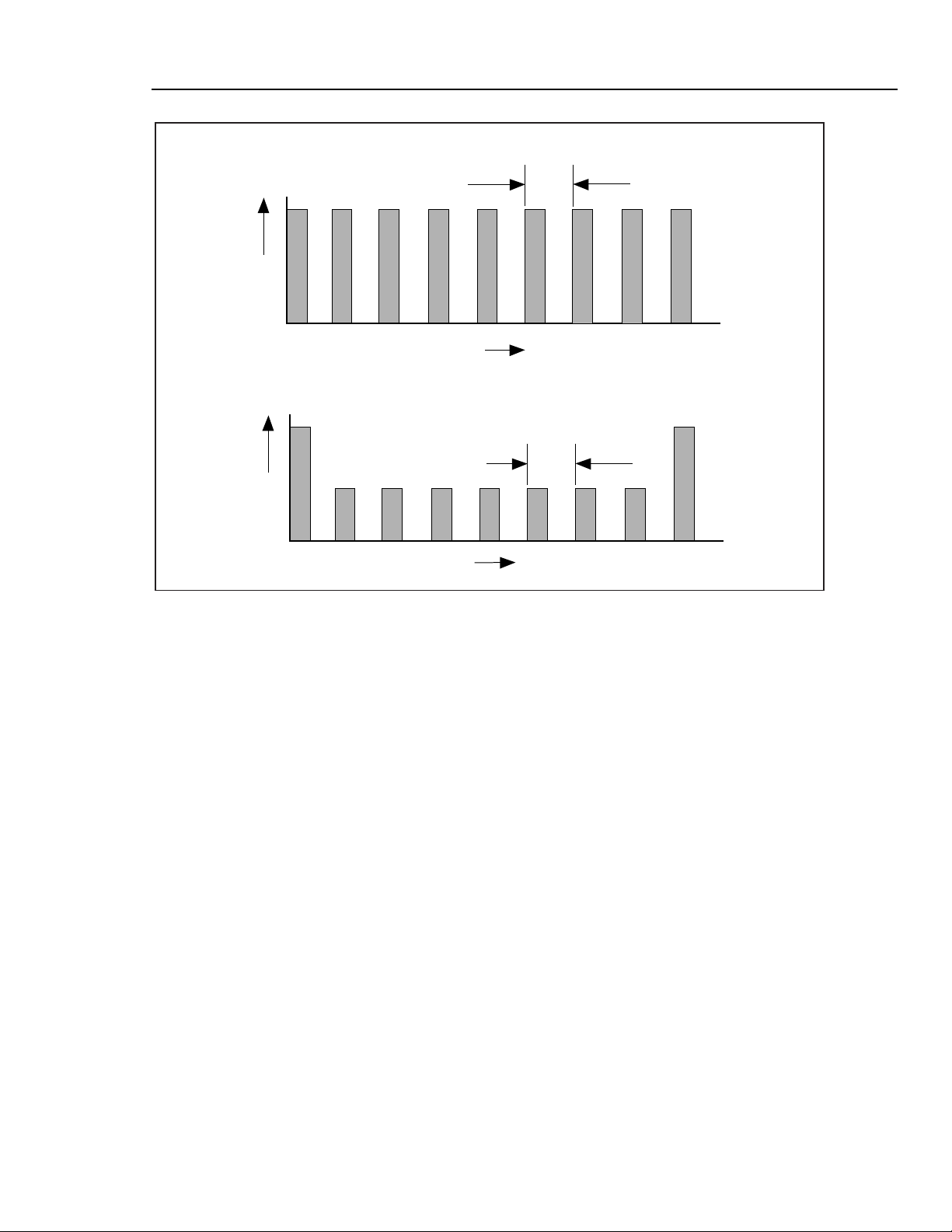
TRADITIONAL CALIBRATOR CALIBRATION
CALIBRATION CYCLE
COST $
CALIBRATION CYCLE
Getting Started
Calibrating the 5700A/5720A Series II Calibrator
TIME
5700A/5720A SERIES II CALIBRATION
COST $
Figure 1. Time and Costs: Calibrator Calibration
The Calibration Process
Calibration requires only three external standards: 10 V, 1 Ω, and 10 kΩ.
Environmentally-controlled internal check standards provide the primary reference
points. A stored table of calibration constants defines additional reference points for
controlling the output. Traceable calibration and adjustment to the specified level of
performance is accomplished in a semi-automated process that revises this table.
When you finish calibration, but before you save the new constants, the calibrator
presents you with the proposed adjustments as +/- ppm of range and percentage change
in specification for each range and function. You can print a list of changes through the
serial (RS-232C) port, or send them to a computer through either the seria l port or the
IEEE-488 port. Also on completion of calibration, the calibrator displays the largest
proposed change.
Calibration can be completed as far as deriving and printing the proposed adjustments
without changing the setting of the rear panel CALIBRATION switch; however, the
switch must be set to ENABLE to store the changes in nonvolatile memory and make
them effective. The switch is recessed to allow the metrologist to cover it with a
calibration sticker to guarantee calibrator integrity.
TIME
alh1.eps
7
Page 22

5700A/5720A Series II
Getting Started
Establishing Traceability
Traceability to national standards is established as follows:
• Except for the internal AC/DC transfer standard, the internal check standards are
• The internal AC/DC transfer standard is never adjusted, so its traceability is not
• Infrequent independent verification is also performed on stable parameters, such as
Calibration Reports
The calibrator stores two sets of calibration constants: the set currently in use and the
old set from the previous calibration. This gives the calibrator the ability at any time to
produce a calibration report of the differences between the present settings and the
settings that were in effect before the last calibration. The report shows changes for
each range and function in +/- ppm of range and in percentage of specification limit.
You can print the report or send it to a host computer through either the RS-232-C or
IEEE-488 interface.
directly calibrated by traceable external standards every time the 5700A/5720A
Series II is calibrated.
disturbed by calibration. Infrequent verification is done in the traditional way, by
comparing selected ac voltage outputs with an external dc voltage standard through
an external ac/dc transfer standard. Fluke recommends this is done every two years
or as determined by the policy of your organization.
frequency flatness, determined more by circuit geometry and dielectric constants
than time.
If you request a calibration report after doing calibration but before saving the new
constants, the report shows proposed changes to the calibration constants relative to the
previously stored settings.
8
Page 23

Calibration Check
Checking the calibration takes about an hour, and provides you with a means of
documenting the calibrator’s performance of a between calibrations. Calibration
checking is similar to calibration, exce pt int ern al check st anda rds are used as primar y
references (no external standards are needed), and changes cannot be stored. The
process produces a report similar to normal ca lib rat ion, showi ng drift rel at ive to
internal check standards. Because cal check does not change stored calibration
constants, there is no need to enable the rear panel CALIBRATION switch. Therefore,
an external computer can do the procedure unattended.
Developing a Performance History
A Fluke specification is a set of performance limits that all products must meet. To
maintain consistent quality, Fluke calibrators are specified with enough margin to
include temperature, line, and load extremes, plus additional margin for production.
This means that a typical 5700A/5720A Series II calibrator in a typical environment
operates inside 50 % of specification limits. For some exacting applications, it can be
helpful to know just how accurately a particular calibrator operates. The proper way to
do this is to accumulate a performance history by calibrating regularly and recording
results on a control chart.
Getting Started
Calibration Check
Calibrating regularly and recording the results on a control chart is tedious and requires
a large array of equipment. The calibrator’s calibration check feature is an alternative
with some distinct advantages:
• Calibrated check standards are already programmed into the unit. You do not have
to use external standards.
• The process is consistent and automatic: it does not require an operator’s
assistance.
Each calibration check produces a new set of data points for accumulating a historical
record. When this process is externally automated, significant history can be
accumulated much faster than with a manual calibration.
Range Calibration
After calibration, you can make further fine adjustments to each range. Range
adjustments are optional; they are not necessary to meet total uncertainty specifications.
However, they do allow you to align your calibrator closer to your standards.
Before you do range calibration, you must first use the calibrator’s semi-automated
calibration procedure. This is to calibrate the ranges that will not be adjusted. It also
performs an initial adjustment for each range, and supplies flatness corrections for ac
functions.
DC Zeros Calibration
To ensure the validity of the specifications, a dc zeros calibration must be performed at
least every 30 days. If more than 30 days elapse without a dc zeros calibration a
warning message appears. This procedure does not require any external equipment or
connections and takes approximately 2.5 minutes to complete.
9
Page 24

5700A/5720A Series II
Getting Started
Specifications
The 5700A/5720A Series II Calibrators are verified and calibrated at the factory prior
to shipment to ensure they meet the accuracy stand ards required for all certified
calibration laboratories. By calibrating to the specifications in this manual, you can
maintain the high performance level throughout the life of your calibrator.
Specifications are valid after a warm-up period of twice the time the calibrator has been
turned off, up to a maximum of 30 minutes. For example, if the calibrator has been
turned off for five minutes, the warm-up period is ten minutes.
Specification Confidence Levels
You calibrator’s performance level is ensured by regular calibration to the primary
performance specifications, which are provided at both the 99 % and 95 % confidence
levels. The 95 % confidence level will provide an accuracy that will often surpass the
accuracy requirements for meeting Tag 4 standards, or a coverage factor of 2.
Calibration at the 99 % confidence level is also available for those applications that
require a confidence factor for the specifications that is higher than 95 %. For
information on selecting the confidence level, refer to Chapter 4 of the Operators
Manual.
The specification tables in this manual provide specifications at both the 95 % and 99
% confidence levels for the 5700A/5720A Series II Calibrators. Included with these
tables are operating specifications for using the calibrator with the Wideband AC
Module (Option 5700A-03) and the 5725A Amplifier.
Using Absolute and Relative Uncertainty Specifications
To evaluate the 5700A/5720A Series II coverage of your calibration workload, use the
Absolute Uncertainty specifications. Absolute uncertainty includes stability,
temperature coefficient, linearity, line and load regulation, and the traceability to
external standards. You do not need to add anything to absolute uncertainty to
determine the ratios between the calibrator’s uncertainties and the uncertainties of your
calibration workload.
Relative uncertainty specifications are provided for enhanced accuracy applications.
These specifications apply when range constants are adjusted (see “Range
Calibration”). To calculate absolute uncertainty, you must combine the uncertainties of
your external standards and techniques with relative uncertainty.
Using Secondary Performance Specifications
Secondary performance specifications and operating characteristics are included in
uncertainty specifications. They are provided for special calibration requirements such
as stability or linearity testing.
10
Page 25

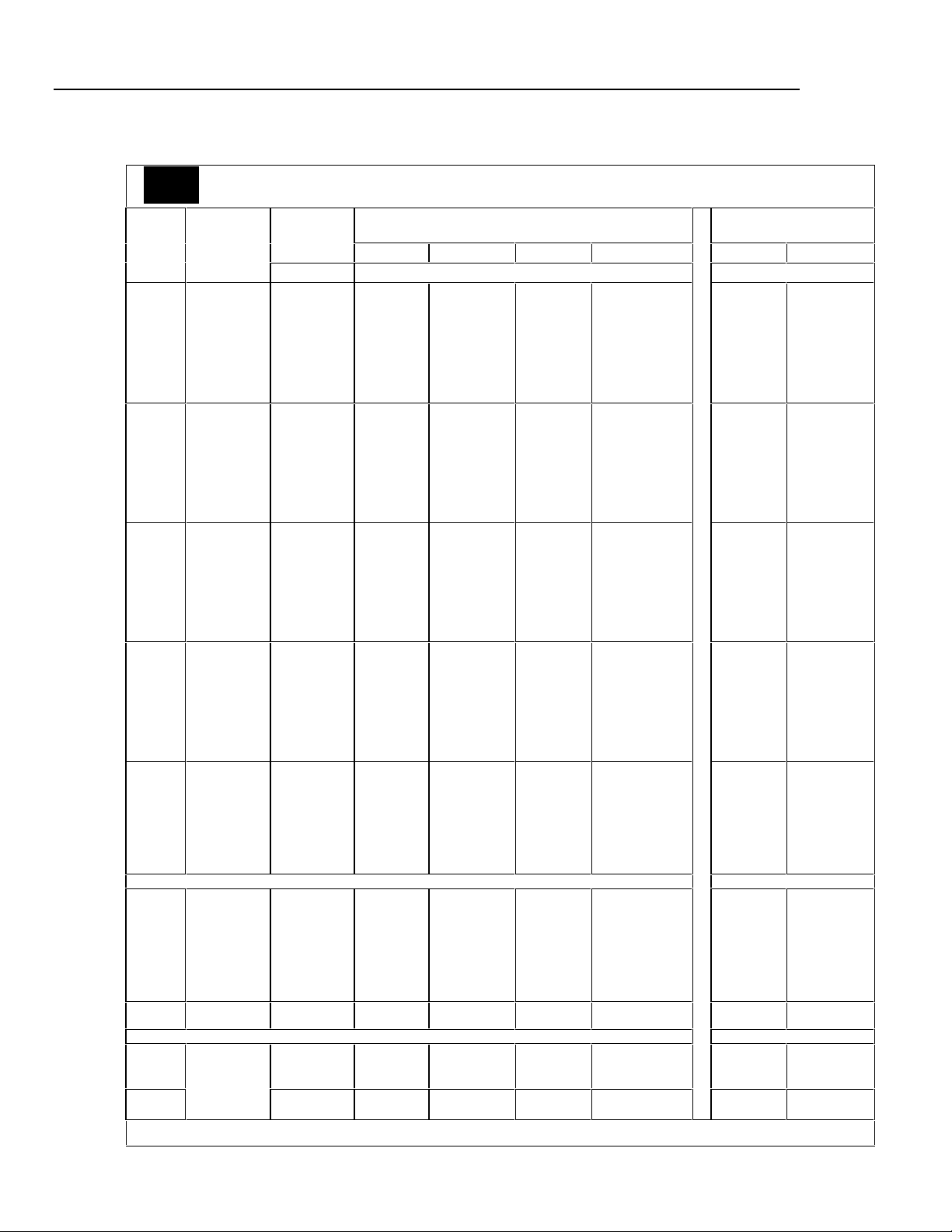
DC Voltage Specificat ions
Table 2. 5720A Series II DC Voltage Specifications: 99 % and 95 % Confidence Levels
5720A
99%
99 % Confidence Level
Getting Started
DC Voltage Specifications
Absolute Uncertainty
± 5 °C from calibration temperature
Range Resolution
220 mV 10 nV 0 5 + 0.5 7 + 0.5 0 8 + 0.5 0 9 + 0.5 0 2 + 0.4 2.5 + 0.4
2.2 V 100 nV 3.5 + 0.8 4 + 0.8 4.5 + 0.8 0 6 + 0.8 0 2 + 0.8 2.5 + 0.8
11 V 1 µV 2.5 + 3 3 + 3 3.5 + 3 0 4 + 3 0 1 + 3 1.5 + 3
22 V 1 µV 2.5 + 5 3 + 5 3.5 + 5 0 4 + 5 0 1 + 5 1.5 + 5
220 V 10 µV 3.5 + 50 4 + 50 0 5 + 50 6 + 50 2 + 50 2.5 + 50
1100 V 100 µV 0 5 + 500 6 + 500 0 7 + 500 8 + 500 2.5 + 400 3 + 400
For fields strengths >1 V/m but ≤3 V/m,
add 0.01% of range.
24 Hours 90 Days 180 Days 1 Year 24 Hours 90 Days
± (ppm output + µV) ± (ppm output + µV)
Relative Uncertainty
± 1 °C
5720A
95%
95% Confidence Level
Range Resolution
Absolute Uncertainty
± 5 °C from calibration temperature
For fields strengths >1 V/m but ≤3 V/m,
add 0.01 % of range.
24 Hours 90 Days 180 Days 1 Year 24 Hours 90 Days
± (ppm output + µV) ± (ppm output + µV)
Relative Uncertainty
± 1 °C
220 mV 10 nV 4 + 0.4 0 6 + 0.4 6.5 + 0.4 7.5 + 0.4 1.6 + 0.4 02 + 0.4
2.2 V 100 nV 3 + 0.7 3.5 + 0.7 0 4 + 0.7 05 + 0.7 1.6 + 0.7 02 + 0.7
11 V 1 µV 2 + 2.5 2.5 + 2.5 03 + 2.5 3.5 + 2.5 0.8 + 2.5 1.2 + 2.5
22 V 1 µV 2 + 4 2.5 + 4 03 + 4 3.5 + 4 0.8 + 4 1.2 + 4
220 V 10 µV 3 + 40 3.5 + 40 04 + 40 0 5 + 40 1.6 + 40 02 + 40
1100 V 100 µV 4 + 400 4.5 + 400 06 + 400 6.5 + 400 02 + 400 2. 4 + 400
11
Page 26

5700A/5720A Series II
Getting Started
Table 3. 5700A Series II DC Voltage Specifications: 99 % and 95 % Confidence Levels
5700A
99%
99 % Confidence Level
Absolute Uncertainty
± 5 °C from calibration temperature
Range Resolution
220 mV 10 nV 6.5 + .75 7 + .75 08 + .75 09 + .8 2.5 + .5 4 + .5
2.2 V 100 nV 3.5 + 1.2 6 + 1. 2 07 + 1.2 08 + 1.2 2.5 + 1.2 4 + 1.2
11 V 1 µV 3.5 + 3 5 + 4 07 + 4 08 + 4 1.5 + 3 3.5 + 4
22 V 1 µV 3.5 + 6 5 + 8 07 + 8 08 + 8 1.5 + 6 3.5 + 8
220 V 10 µV 5 + 100 6 + 100 08 + 100 09 + 100 2.5 + 100 4 + 100
1100 V 100 µV 7 + 600 8 + 600 10 + 600 11 + 600 3 + 600 4.5 + 600
For fields strengths >1 V/m but ≤3 V/m,
add 0.01 % of range.
24 Hours 90 Days 180 Days 1 Year 24 Hours 90 Days
± (ppm output + µV) ± (ppm output + µV)
Relative Uncertainty
± 1 °C
5700A
95%
95 % Confidence Level
Range Resolution
Absolute Uncertainty
± 5 °C from calibration temperature
For fields strengths >1 V/m but ≤3 V/m,
add 0.01 % of range.
24 Hours 90 Days 180 Days 1 Year 24 Hours 90 Days
± (ppm output + µV) ± (ppm output + µV)
Relative Uncertainty
± 1 °C
12
220 mV 10 nV 5.5 + 0.6 6 + 0.6 7 + 0.6 8 + 0.6 2 + 0.4 3.5 + 0.4
2.2 V 100 nV 3.5 + 1 5 + 1 6 + 1 7 + 1 2 + 1 3.5 + 1
11 V 1 mV 3 + 3.5 4 + 3.5 6 + 3.5 7 + 3.5 1.2 + 3 3 + 3.5
22 V 1 mV 3 + 6.5 4 + 6.5 6 + 6.5 7 + 6.5 1.2 + 6 3 + 7
220 V 10 mV 4 + 80 5 + 80 7 + 80 8 + 80 2 + 80 3.5 + 80
1100 V 100 mV 6 + 500 7 + 500 8 + 500 9 + 500 2.4 + 500 4 + 500
Page 27

DC Voltage Specifications
Table 4. DC Voltage Secondary Performance Specifications and Operating Characteristics
Getting Started
Range Stability [Note 1]
220 mV
2.2 V
11 V
22 V
220 V
1100 V
± 1 °C
24 Hours 40°-50 °C pk-pk RMS
± (ppm output + µV) ± (ppm output + µV)/°C ± (ppm output + µV) µV
0.3 + 0.3
0.3 + 1
0.3 + 2.5
0.4 + 5
0.5 + 40
0.5 + 200
Temperature Coefficient
Adder [Note 2]
10 °-40 °C 0 °-10 °C
00.4 + 0.1
00.3 + 0.1
0.15 + 0.2
00.2 + 0.4
00.3 + 5
00.5 + 10
and
1.5 + 0.5
1.5 + 2
0 1 + 1.5
1.5 + 3
1.5 + 40
0 3 + 200
Linearity
± 1 °C
0 1 + 0.2
0 1 + 0.6
0.3 + 2
0.3 + 4
0 1 + 40
0 1 + 200
Bandwidth
0.1-10 Hz
0.15 + 0.1
0.15 + 0.4
0.15 + 2
0.15 + 4
0.15 + 60
0.15 + 300
Noise
Bandwidth
10 Hz-10 kHz
5
15
50
50
150
500
Notes:
1. Stability specifications are included in the Absolute Uncertainty values in the primary specification
tables.
2. Temperature coefficient is an adder to uncertainty specifications that does
not
apply unless operating
more than ±5 °C from calibration temperature.
Minimum output: 0 V for all ranges, except 100 V for 1100 V range
Maximum load: 50 mA for 2.2 V through 220 V ranges; 20 mA for 1100 V range; 50 Ω output impedance
on 220 mV range; all ranges <1000 pF, >25 Ω
Load regulation: <(0.2 ppm of output + 0.1ppm of range), full load to no load
Line regulation: <0.1 ppm change, ± 10 % of selected nominal line
Settling time: 3 seconds to full accuracy; + 1 second for range or polarity change; + 1 second for 1100 V
range
Overshoot: <5 %
Common mode rejection: 140 dB, DC to 400 Hz
Remote sensing: Available 0 V to ±1100 V, on 2.2 V through 1100 V ranges
13
Page 28
5700A/5720A Series II
0
0
Getting Started
AC Voltage Specificat ions
5720A
99%
99 % Confidence Level
Range Resolution Frequency
2.2 mV 1 nV
22 mV 10 nV
220 mV 100 nV
2.2 V 1 mV
22 V 10 mV
220 V
[Note 2]
1100 V
5725A Amplifier:
1100 V
750 V
Notes: 1. Maximum output 250V from 15- 50 Hz.
2. See Volt-Hertz capability in Figure 1-2.
Table 5. 5720A Series II AC Voltage Specifications: 99 % Confidence Level
Absolute Uncertainty
± 5 °C from calibration temperature
24 Hours 90 Days 180 Days 1 Year 24 Hours 90 Days
Hz ± (ppm output + µV) ± (ppm output + µV)
100 mV
1 mV
[Note 1]
1 mV
0010 - 20
0020 - 40
0040 - 20 k
020 k - 50 k
050 k - 100 k
100 k - 300 k
300 k - 500 k
500 k - 1 M
0010 - 20
0020 - 40
0040 - 20 k
020 k - 50 k
050 k - 100 k
100 k - 300 k
300 k - 500 k
500 k - 1 M
0010 - 20
0020 - 40
0040 - 20 k
020 k - 50 k
050 k - 100 k
100 k - 300 k
300 k - 500 k
500 k - 1 M
0010 - 20
0020 - 40
0040 - 20 k
020 k - 50 k
050 k - 100 k
100 k - 300 k
300 k - 500 k
500 k - 1 M
0010 - 20
0020 - 40
0040 - 20 k
020 k - 50 k
050 k - 100 k
100 k - 300 k
300 k - 500 k
500 k - 1 M
0010 - 20
0020 - 40
0040 - 20 k
020 k - 50 k
050 k - 100 k
100 k - 300 k
300 k - 500 k
500 k - 1 M
0015 - 50
0050 - 1 k
0040 - 1 k
001 k - 20 k
020 k - 30 k
030 k - 50 k
050 k - 100k
0250 + 5
0100 + 5
0085 + 5
0220 + 5
0500 + 6
1000 + 12
1400 + 25
2900 + 25
0250 + 5
0100 + 5
0085 + 5
0220 + 5
0500 + 6
1000 + 12
1400 + 25
2900 + 25
0250 + 15
0100 + 8
0085 + 8
0220 + 8
0500 + 20
0850 + 25
1400 + 30
2700 + 60
0250 + 50
0095 + 20
0045 + 10
0080 + 12
0120 + 40
0380 + 100
1000 + 250
1600 + 400
0250 + 500
0095 + 200
0045 + 70
0080 + 120
0110 + 250
0300 + 800
1000 + 250
1500 + 400
0270 + 5
0105 + 5
0090 + 5
0230 + 5
0540 + 6
1200 + 12
1500 + 25
3100 + 25
0270 + 5
0105 + 5
0090 + 5
0230 + 5
0540 + 6
1200 + 12
1500 + 25
3100 + 25
0270 + 15
0105 + 8
0090 + 8
0230 + 8
0540 + 20
0900 + 25
1500 + 30
2900 + 60
0270 + 50
0100 + 20
0047 + 10
0085 + 12
0125 + 40
0420 + 100
1100 + 250
1800 + 600
0270 + 500
0100 + 200
0047 + 70
0085 + 120
0115 + 250
0310 + 800
1100 + 2500
1600 + 4000
0290 + 5
0110 + 5
0095 + 5
0240 + 5
0570 + 6
1250 + 12
1600 + 25
3250 + 25
0290 + 5
0110 + 5
0095 + 5
0240 + 5
0570 + 6
1250 + 12
1600 + 25
3250 + 25
0290 + 15
0110 + 8
0095 + 8
0240 + 8
0570 + 20
1000 + 25
1600 + 30
3100 + 60
0290 + 50
0105 + 20
0050 + 10
0087 + 12
0127 + 40
0460 + 100
1150 + 250
1900 + 400
0290 + 500
0105 + 200
0050 + 70
0087 + 120
0117 + 250
0320 + 800
1150 + 2500
1700 + 4000
00300 + 5
00115 + 5
00100 + 5
00250 + 5
00600 + 6
01300 + 12
01700 + 25
03400 + 25
00300 + 5
00115 + 5
00100 + 5
00250 + 5
00600 + 6
01300 + 12
01700 + 25
03400 + 25
00300 + 15
00115 + 8
00100 + 8
00250 + 8
00600 + 20
01100 + 25
01700 + 30
03300 + 60
00300 + 50
00110 + 20
00052 + 10
00090 + 12
00130 + 40
00500 + 100
01200 + 250
02000 + 400
00300 + 500
00110 + 200
00052 + 70
00090 + 120
00120 + 250
00325 + 800
01200 + 2500
01800 + 4000
± (ppm output + mV) ± (ppm output + mV)
0250 + 5
0095 + 2
0057 + 0.7
0090 + 1.2
0160 + 3
0900 + 20
5000 + 50
8000 + 100
0300 + 20
0070 + 4
0075 + 4
0105 + 6
0230 + 11
0230 + 11
0600 + 45
0270 + 5
0100 + 2
0060 + 0.7
0095 + 1.2
0170 + 3
1000 + 20
5200 + 50
9000 + 100
0320 + 20
0075 + 4
0080 + 4
0125 + 6
0360 + 11
0360 + 11
1300 + 45
0290 + 5
0105 + 2
0062 + 0.7
0097 + 1.2
0175 + 3
1050 + 20
5300 + 50
9500 + 100
0340 + 20
0080 + 4
0085 + 4
0135 + 6
0440 + 11
0440 + 11
1600 + 45
00300 + 5
00110 + 2
00065 + 0.7
00100 + 1.2
00 180 + 3
0 1100 + 20
0 5400 + 50
10,000 + 100
00 360 + 20
00085 + 4
000 90 + 4
00 165 + 6
00 600 + 11
00600 + 11
02300 + 45
Relative Uncertainty
± 1 °C
0250 + 5
0100 + 5
0060 + 5
0085 + 5
0200 + 6
0350 + 12
0800 + 25
2700 + 25
0250 + 5
0100 + 5
0060 + 5
0085 + 5
0200 + 6
0350 + 12
0800 + 25
2700 + 25
0250 + 15
0100 + 8
0060 + 8
0085 + 8
0200 + 20
0350 + 25
0800 + 30
2600 + 60
0250 + 50
0095 + 20
0030 + 10
0070 + 12
0100 + 40
0270 + 100
0900 + 250
1200 + 400
0250 + 500
0095 + 200
0030 + 70
0070 + 120
0100 + 250
0270 + 800
0900 + 2500
1300 + 4000
0250 + 5
0095 + 2
0045 + 0.7
0075 + 1.2
0140 + 3
0600 + 20
4500 + 50
8000 + 100
0300 + 20
0050 + 4
0050 + 4
0085 + 6
0160 + 11
0160 + 11
0380 + 45
0270 + 5
0105 + 5
0065 + 5
0095 + 5
0220 + 6
0400 + 12
1000 + 25
3000 + 25
0270 + 5
0105 + 5
0065 + 5
0095 + 5
0220 + 6
0400 + 12
1000 + 25
3000 + 25
0270 + 15
0105 + 8
0065 + 8
0095 + 8
0220 + 20
0400 + 25
1000 + 30
2800 + 60
0270 + 50
0100 + 20
0040 + 10
0075 + 12
0105 + 40
0290 + 100
1000 + 250
1300 + 400
0270 + 500
0100 + 200
0040 + 70
0075 + 120
0105 + 250
0290 + 800
1000 + 2500
1400 + 4000
0270 + 5
0100 + 2
0050 + 0.7
0080 + 1.2
0150 + 3
0700 + 20
4700 + 50
8500 + 100
0320 + 20
0055 + 4
0055 + 4
0105 + 6
0320 + 11
0320 + 11
1200 + 45
14
Page 29

Table 6. 5720A Series II AC Voltage Specifications: 95 % Confidence Level
0
0
5720A
95%
95 % Confidence Level
Range Resolution Frequency
Hz ± (ppm output + µV) ± (ppm output + µV)
0010 - 20
0020 - 40
0040 - 20 k
2.2 mV 1 nV
22 mV 10 nV
220 mV 100 nV
2.2 V 1 mV
22V 10 mV
220 V
[Note 2]
1100 V
1100 V
750 V
Notes: 1. Maximum output 250V from 15-50 Hz.
100 mV
1 mV
[Note 1]
1 mV
2. See Volt-Hertz capability in Figure 1-2.
020 k - 50 k
050 k - 100 k
100 k - 300 k
300 k - 500 k
500 k - 1 M
0010 - 20
0020 - 40
0040 - 20 k
020 k - 50 k
050 k - 100 k
100 k - 300 k
300 k - 500 k
500 k - 1 M
0010 - 20
0020 - 40
0040 - 20 k
020 k - 50 k
050 k - 100 k
100 k - 300 k
300 k - 500 k
500 k - 1 M
00010 - 20
0020 - 40
0040 - 20 k
020 k - 50 k
050 k - 100 k
100 k - 300 k
300 k - 500 k
500 k - 1 M
0010 - 20
0020 - 40
0040 - 20k
020k - 50k
050k - 100k
100k - 300k
300k - 500k
500k - 1M
± (ppm output + mV) ± (ppm output + mV)
0010 - 20
0020 - 40
0040 - 20 k
020 k - 50 k
050 k - 100 k
100 k - 300 k
300 k - 500 k
500 k - 1 M
0015 - 50
0050 - 1 k
5725A Amplifier:
0040 - 1 k
001 k - 20 k
020 k - 30 k
030 k - 50 k
050 k - 100 k
Getting Started
AC Voltage Specificati on s
Absolute Uncertainty
± 5 °C from calibration temperature
24 Hours 90 Days 180 Days 1 Year 24 Hours 90 Days
0200 + 4
0080 + 4
0070 + 4
0170 + 4
0400 + 5
0300 + 10
1100 + 20
2400 + 20
0200 + 4
0080 + 4
0070 + 4
0170 + 4
0400 + 5
0300 + 10
1100 + 20
2400 + 20
0200 + 12
0080 + 7
0070 + 7
0170 + 7
0400 + 17
0700 + 20
1100 + 25
2400 + 45
0200 + 40
0075 + 15
0037 + 8
0065 + 10
0100 + 30
0300 + 80
0800 + 200
1300 + 300
0200 + 400
0075 + 150
0037 + 50
0065 + 100
0090 + 200
0250 + 600
0800 + 200
1200 + 320
0200 +4
0075 + 1.5
0045 + 0.6
0070 + 1
0120 + 2.5
0700 + 16
4000 + 40
6000 + 80
0240 + 16
0055 + 3.5
0075 + 4
0105 + 6
0230 + 11
0230 + 11
0600 + 45
0220 + 4
0085 + 4
0075 + 4
0180 + 4
0460 + 5
0900 + 10
1200 + 20
2500 + 20
0220 + 4
0085 + 4
0075 + 4
0180 + 4
0460 + 5
0900 + 10
1200 + 20
2500 + 20
0220 + 12
0085 + 7
0075 + 7
0180 + 7
0420 + 17
0750 + 20
1200 +25
2500 + 45
0220 + 40
0080 + 15
0040 + 8
0070 + 10
0105 + 30
0340 + 80
0900 + 200
1500 + 300
0220 + 400
0080 + 150
0040 + 50
0070 + 100
0095 + 200
0260 + 600
0900 + 2000
1300 + 3200
0220 + 4
0080 + 1.5
0047 + 0.6
0075 + 1
0130 + 2.5
0800 + 16
4200 + 40
7000 + 80
0260 + 16
0060 + 3.5
0080 + 4
0125 + 6
0360 + 11
0360 + 11
1300 + 45
0230 + 4
0087 + 4
0077 + 4
0190 + 4
0480 + 5
1000 + 10
1300 + 20
2600 + 20
0230 + 4
0087 + 4
0077 + 4
0190 + 4
0480 + 5
1000 + 10
1300 + 20
2600 + 20
0230 + 12
0087 + 7
0077 + 7
0190 + 7
0440 + 17
0800 + 20
1300 + 25
2600 + 45
0230 + 40
0085 + 15
0042 + 8
0073 + 10
0107 + 30
0380 + 80
0950 + 200
1600 + 300
0230 + 400
0085 + 150
0042 + 50
0073 + 100
0097 + 200
0270 + 600
0900 + 2000
1400 + 3200
0230 + 4
0085 + 1.5
0050 + 0.6
0077 + 1
0140 + 2.5
0850 + 16
4300 + 40
7500 + 80
0280 + 16
0065 + 3.5
0085 + 4
0135 + 6
0440 + 11
0440 + 11
1600 + 45
0240 + 4
0090 + 4
0080 + 4
0200 + 4
0500 + 5
1050 + 10
1400 + 20
2700 + 20
0240 + 4
0090 + 4
0080 + 4
0200 + 4
0500 + 5
1050 + 10
1400 + 20
2700 + 20
0240 + 12
0090 + 7
0080 + 7
0200 + 7
0460 + 17
0900 + 20
1400 + 25
2700 + 45
0240 + 40
0090 + 15
0045 + 8
0075 + 10
0110 + 30
0420 + 80
1000 + 200
1700 + 300
0240 + 400
0090 + 150
0045 + 50
0075 + 100
0100 + 200
0275 + 600
1000 + 2000
1500 + 3200
0240 + 4
0090 + 1.5
0052 + 0.6
0080 + 1
0150 + 2.5
0900 + 16
4400 + 40
8000 + 80
0300 + 16
0070 + 3.5
0090 + 4
0165 + 6
0600 + 11
0600 + 11
2300 + 45
Relative Uncertainty
± 1 °C
0200 + 4
0080 + 4
0050 + 4
0070 + 4
0160 + 5
0280 + 10
0650 + 20
2100 + 20
0200 + 4
0080 + 4
0050 + 4
0070 + 4
0160 + 5
0280 + 10
0650 + 20
2100 + 20
0200 + 12
0080 + 7
0050 + 7
0070 + 7
0160 + 17
0280 + 20
0650 + 25
2100 + 45
0200 + 40
0075 + 15
0025 + 8
0055 + 10
0080 + 30
0230 + 80
0700 + 200
1000 + 300
0200 + 400
0075 + 150
0025 + 50
0055 + 100
0080 + 200
0250 + 600
0700 + 2000
1100 + 3200
0200 + 4
0075 + 1.5
0035 + 0.6
0060 + 1
0110 + 2.5
0500 + 16
3600 + 40
6500 + 80
0240 + 16
0040 + 3.5
0050 + 4
0085 + 6
0160 + 11
0160 + 11
0380 + 45
0220 + 4
0085 + 4
0055 + 4
0080 + 4
0180 + 5
0320 + 10
0800 + 20
2400 + 20
0220 + 4
0085 + 4
0055 + 4
0080 + 4
0180 + 5
0320 + 10
0800 + 20
2400 + 20
0220 + 12
0085 + 7
0055 + 7
0080 + 7
0180 + 17
0320 + 20
0800 + 25
2400 + 45
0220 + 40
0080 + 15
0035 + 8
0060 + 10
0085 + 30
0250 + 80
0800 + 200
1100 + 300
0220 + 400
0080 + 150
0035 + 50
0060 + 100
0085 + 200
0270 + 600
0800 + 2000
1200 + 3200
0220 + 4
0080 + 1.5
0040 + 0.6
0065 + 1
0120 + 2.5
0600 + 16
3800 + 40
7000 + 80
0260 + 16
0045 + 3.5
0055 + 4
0105 + 6
0320 + 11
0320 + 11
1200 + 45
15
Page 30

5700A/5720A Series II
0
0
0
0
0
0
0
0
0
0
0
0
0
0
0
0
0
0
0
0
0
0
0
0
0
0
0
0
0
0
0
0
0
0
0
0
0
0
0
0
0
0
0
0
0
0
0
0
0
0
0
0
0
0
0
0
0
0
0
0
0
0
0
0
0
0
0
0
0
0
0
0
0
0
0
0
0
0
0
0
0
0
0
0
0
0
0
0
0
0
0
0
0
0
0
0
0
0
0
0
0
0
0
0
0
0
0
0
0
0
0
0
0
0
0
0
0
0
0
0
0
0
0
0
0
0
0
0
0
0
0
0
0
0
0
0
0
0
0
0
0
0
0
0
0
0
0
0
0
0
0
0
0
0
0
0
0
0
0
0
0
0
0
0
0
0
0
0
0
0
0
0
0
0
0
0
0
0
0
0
0
0
0
0
0
0
0
0
0
0
0
0
0
0
0
0
0
0
13,000 + 220
0
0
0
0
0
0
0
0
0
0
0
0
0
0
0
0
0
0
0
0
0
0
0
0
0
0
0
0
0
0
0
0
0
0
0
0
0
0
Getting Started
Table 7. 5700A Series II AC Voltage Specifications: 99 % Confidence Level
5700A
99%
99 % Confidence Level
Range Resolution Frequency
2.2 mV 1 nV
22 mV 10 nV
220 mV 100 nV
2.2 V 1 mV
22 V 10 mV
220 V
[Note 2]
1100 V 1 mV
100 mV
[Note 1]
5725A Amplifier:
1100 V 1 mV 00040 - 1 k
750 V 0030 k - 50 k
Notes: 1. Maximum output 250V from 15- 50 Hz.
2. See Volt-Hertz capability in Figure 1-2.
0010 - 20
0020 - 40
0040 - 20 k
020 k - 50 k
050 k - 100 k
100 k - 300 k
300 k - 500 k
500 k - 1 M
0010 - 20
0020 - 40
0040 - 20 k
020 k - 50 k
050 k - 100 k
100 k - 300 k
300 k - 500 k
500 k - 1 M
0010 - 20
0020 - 40
0040 - 20 k
020 k - 50 k
050 k - 100 k
100 k - 300 k
300 k - 500 k
500 k - 1 M
0010 - 20
0020 - 40
0040 - 20 k
020 k - 50 k
050 k - 100 k
100 k - 300 k
300 k - 500 k
500 k - 1 M
0010 - 20
0020 - 40
0040 - 20 k
020 k - 50 k
050 k - 100 k
100 k - 300 k
300 k - 500 k
500 k - 1 M
0010 - 20
0020 - 40
0040 - 20 k
020 k - 50 k
050 k - 100 k
100 k - 300 k
300 k - 500 k
500 k - 1 M
00015 - 50
00050 - 1 k
0001 k - 20 k
0020 k - 30 k
0050 k - 100 k
Absolute Uncertainty
± 5 °C from calibration temperature
Relative Uncertainty
± 1 °C
24 Hours 90 Days 180 Days 1 Year 24 Hours 90 Days
Hz ± (ppm output + µV) ± (ppm output + µV)
0 500 + 5
00200 + 5
0 100 + 5
0 340 + 5
0 800 + 8
01100 + 15
01500 + 30
4000 + 40
0 500 + 6
0 200 + 6
0100 + 6
0340 + 6
0800 + 8
1100 + 15
01500 + 30
04000 + 40
0500 + 16
0 200 + 10
0 095 + 10
0 300 + 10
0 750 + 30
0 940 + 30
1500 + 40
3000 + 100
0 500 + 100
0 150 + 30
00 70 + 7
0 120 + 20
0 230 + 80
0 400 + 150
1000 + 400
2000 + 1000
0 500 + 1000
0 150 + 300
00 70 + 70
0 120 + 200
0 230 + 400
0 500 + 1700
1200 + 5000
2600 + 9000
0 550 + 5
0 220 + 5
0 110 + 5
0 370 + 5
0 900 + 8
01200 + 15
01700 + 30
04400 + 40
0 550 + 6
0 220 + 6
0 110 + 6
0 370 + 6
0 900 + 8
01200 + 15
01700 + 30
04400 + 40
0 550 + 16
0 220 + 10
0 100 + 10
0 330 + 10
0 800 + 30
1000 + 30
01700 + 40
03300 + 100
0 550 + 100
0 170 + 30
00 75 + 7
0 130 + 20
0 250 + 80
0 440 + 150
1100 + 400
2200 + 1000
0 550 + 1000
0 170 + 300
00 75 + 70
0 130 + 200
0 250 + 400
0 550 + 1700
1300 + 5000
2800 + 9000
0 600 + 5
0 230 + 5
0 120 + 5
0 390 + 5
0 950 + 8
1300 + 15
01700 + 30
4700 + 40
00600 + 6
0 230 + 6
0 120 + 6
0 390 + 6
0 950 + 8
1300 + 15
1700 + 30
4700 + 40
0 600 + 16
0 230 + 10
0 110 + 10
0 350 + 10
0 850 + 30
01100 + 30
1700 + 40
3500 + 100
0 600 + 100
0 170 + 30
00 80 + 7
0 140 + 20
0 270 + 80
0 470 + 150
1200 + 400
2300 + 1000
0 600 + 1000
0 170 + 300
00 80 + 70
0 140 + 200
0 270 + 400
0 550 + 1700
1300 + 5000
2900 + 9000
0 600 + 5
0 240 + 5
0 120 + 5
0 410 + 5
0950 + 8
1300 + 15
1800 + 30
4800 + 40
0600 + 6
0 240 + 6
0 120 + 6
0 410 + 6
0 950 + 8
1300 + 15
1800 + 30
4800 + 40
0 600 + 16
00240 + 10
00110 + 10
00360 + 10
0900 + 30
01100 + 30
01800 + 40
03600 + 100
0 600 + 100
0 180 + 30
00 85 + 7
0 140 + 20
0 280 + 80
0 480 + 150
1200 + 400
2400 + 1000
0 600 + 1000
0 180 + 300
00 85 + 70
0 140 + 200
0 280 + 400
0 600 + 1700
1400 + 5000
3000 + 9000
00 500 + 5
00 200 + 5
000 60 + 5
00 100 + 5
00 220 + 8
00 400 + 15
01000 + 30
00 400 + 30
00 500 + 6
00 200 + 6
000 60 + 6
00 100 + 6
00 220 + 8
00 400 + 15
01000 + 30
0 4000 + 30
00 500 + 16
00200 + 10
00060 + 10
00100 + 10
00220 + 30
00400 + 30
01000 + 40
03000 + 100
00 500 + 100
00 150 + 30
000 40 + 7
00 100 + 20
00 200 + 80
00 400 + 150
0 1000 + 400
0 2000 + 1000
00 500 + 1000
00 150 + 300
000 40 + 70
00 100 + 200
00 200 + 400
00500 + 1700
01200 + 5000
02600 + 9000
0 550 + 5
0220 + 5
0 065 + 5
0 110 + 5
0 240 + 8
0 440 + 15
1100 + 30
4400 + 30
0 550 + 6
0 220 + 6
00 65 + 6
0 110 + 6
0 240 + 8
0 440 + 15
1100 + 30
4400 + 30
00550 + 16
00220 + 10
00065 + 10
00110 + 10
00240 + 30
00440 + 30
01100 + 40
03300 + 100
0 550 + 100
0 170 + 30
00 45 + 7
0 110 + 20
0 220 + 80
0 440 + 150
1100 + 400
2200 + 1000
0 550 + 1000
0 170 + 300
00 45 + 70
0 110 + 200
0 220 + 400
0 550 + 1700
1300 + 5000
2800 + 9000
± (ppm output + mV) ± (ppm output + mV)
0 500 + 10
0 150 + 3
00 75 + 1
0 200 + 4
0 500 + 10
1500 + 110
5000 + 110
12,000 + 220
0 400 + 20
00 75 + 4
00 75 + 4
0 105 + 6
0 230 + 11
0 230 + 11
0 600 + 45
0 550 + 10
0 170 + 3
00 80 + 1
0 220 + 4
0 550 + 10
1500 + 110
5200 + 110
12,500 + 220
00420 + 20
00 80 + 4
00 80 + 4
0 125 + 6
0 360 + 11
0 360 + 11
1300 + 45
0600 + 10
0 170 + 3
00 85 + 1
0 240 + 4
0 600 + 10
1600 + 110
5300 + 110
12,500 + 220
00440 + 20
00 85 + 4
00 85 + 4
0 135 + 6
0 440 + 11
0 440 + 11
1600 + 45
0 600 + 10
0 180 + 3
00 90 + 1
0 250 + 4
0 600 + 10
1600 + 110
5400 + 110
00460 + 20
00 90 + 4
00 90 + 4
0 165 + 6
0 600 + 11
0 600 + 11
2300 + 45
00 500 + 10
00 150 + 3
000 45 + 1
00 100 + 1
00 300 + 10
01500 + 110
0 5000 + 110
12,000 + 220
00400 + 20
000 50 + 4
000 50 + 4
000 85 + 6
00 160 + 11
00 160 + 11
00 380 + 45
0 550 + 10
0 170 + 3
00 50 + 1
0 110 + 1
0 330 + 10
1500 + 100
5200 + 110
12,000 + 220
00420 + 20
00 55 + 4
00 55 + 4
0 105 + 6
0 320 + 11
0 320 + 11
1200 + 45
16
Page 31

Table 8. 5700A Series II AC Voltage Specifications: 95 % Confidence Level
0
0
0
0
0
0
0
0
0
0
0
0
0
0
0
0
0
0
0
0
0
0
0
0
0
0
0
0
0
0
0
0
0
0
0
0
0
0
0
0
0
0
0
0
0
0
0
0
0
0
0
0
0
0
0
0
0
0
0
0
0
0
0
0
0
0
0
0
0
0
0
0
0
0
0
0
0
0
0
0
0
0
0
0
0
0
0
0
0
0
0
0
0
0
0
0
0
0
0
0
0
0
0
0
0
0
0
0
0
0
0
0
0
0
0
0
0
0
0
0
0
0
0
0
0
0
0
0
0
0
0
0
0
0
0
0
0
0
0
0
0
0
0
0
0
0
0
0
0
0
0
0
0
0
0
0
0
0
0
0
0
0
0
0
0
0
0
0
0
0
0
0
0
0
0
0
0
0
0
0
0
0
0
0
0
0
0
0
0
0
0
0
0
0
0
0
0
0
0
0
0
0
0
0
0
0
0
0
0
0
0
0
0
0
0
0
0
0
0
0
0
11,300 + 190
0
0
0
0
0
0
0
0
0
0
0
0
0
0
0
0
0
0
0
0
0
0
0
0
0
0
0
0
0
0
0
0
0
0
0
0
0
0
0
0
0
0
0
0
0
5700A
95%
95% Confidence Level
Range Resolution Frequency
Hz ± (ppm output + µV) ± (ppm output + µV)
0010 - 20
0020 - 40
2.2 mV 1 nV
22 mV 10 nV
220 mV 100 nV
2.2 V 1 mV
22 V 10 mV
220 V
[Note 2]
1100 V
1100 V
750 V
Notes: 1. Maximum output 250V from 15- 50 Hz.
100 mV
1 mV
[Note 1]
1 mV
2. See Volt-Hertz capability in Figure 1-2.
0040 - 20 k
020 k - 50 k
050 k - 100 k
100 k - 300 k
300 k - 500 k
500 k - 1 M
0010 - 20
0020 - 40
0040 - 20 k
020 k - 50 k
050 k - 100 k
100 k - 300 k
300 k - 500 k
500 k - 1 M
0010 - 20
0020 - 40
0040 - 20 k
020 k - 50 k
050 k - 100 k
100 k - 300 k
300 k - 500 k
500 k - 1 M
0010 - 20
0020 - 40
0040 - 20 k
020 k - 50 k
050 k - 100 k
100 k - 300 k
300 k - 500 k
500 k - 1 M
0010 - 20
0020 - 40
0040 - 20 k
020 k - 50 k
050 k - 100 k
100 k - 300 k
300 k - 500 k
500 k - 1 M
0010 - 20
0020 - 40
0040 - 20 k
020 k - 50 k
050 k - 100 k
100 k - 300 k
300 k - 500 k
500 k - 1 M
0015 - 50
0050 - 1 k
0040 - 1 k
001 k - 20 k
020 k - 30 k
030 k - 50 k
050 k - 100 k
± (ppm output + mV) ± (ppm output + mV)
10,500 + 190
5725A Amplifier:
Getting Started
AC Voltage Specificati on s
Absolute Uncertainty
± 5 °C from calibration temperature
24 Hours 90 Days 180 Days 1 Year 24 Hours 90 Days
0 400 + 4.5
0 170 + 4.5
00 85 + 4.5
0 300 + 4.5
0 700 + 7
0 900 + 13
1300 + 25
2800 + 25
0 400 + 5
0 170 + 5
00 85 + 5
0 300 + 5
0 700 + 7
0 900 + 12
1300 + 25
2800 + 25
0 400 + 13
0 170 + 8
00 85 + 8
0 250 + 8
0 700 + 25
0 900 + 25
1300 + 35
2800 + 80
0 400 + 80
0 130 + 25
00 60 + 6
0 105 + 16
0 190 + 70
0 350 + 130
0 850 + 350
1700 + 850
0 400 + 800
0 130 + 250
00 60 + 60
0 105 + 160
0 190 + 350
0 400 + 1500
1050 + 4300
2300 + 8500
0 400 + 8
0 130 + 2.5
00 65 + 0.8
0 170 + 3.5
0 400 + 8
1300 + 90
4300 + 90
0 340 + 16
00 65 + 3.5
00 75 + 4
0 105 + 6
0 230 + 11
0 230 + 11
0 600 + 45
0 500 + 4.5
0 190 + 4.5
00 95 + 4.5
0 330 + 4.5
0750 + 7
1000 + 13
1500 + 25
3100 + 25
0 500 + 5
0 190 + 5
00 95 + 5
0 330 + 5
0 750 + 7
1000 + 12
1500 + 25
3100 + 25
0 500 + 13
0 190 + 8
00 95 + 8
0 280 + 8
0 750 + 25
1000 + 25
1500 + 35
3100 + 80
0 450 + 80
0 140 + 25
00 65 + 6
0 110 + 16
0 210 + 70
0 390 + 130
0950 + 350
1900 + 850
0 450 + 800
0 140 + 250
00 65 + 60
0 110 + 160
0 210 + 350
0 450 + 1500
1150 + 4300
2500 + 8500
0 450 + 8
0 140 + 2.5
00 70 + 0.8
0 190 + 3.5
0 450 + 8
1400 + 90
4500 + 90
11,000 + 190
00360 + 16
00 70 + 3.5
00 80 + 4
0 125 + 6
0 360 + 11
0 360 + 11
1300 + 45
0 530 + 4.5
0 200 + 4.5
0 100 + 4.5
0 350 + 4.5
0 800 + 7
1050 + 13
1600 + 25
3300 + 25
0 530 + 5
0 200 + 5
0 100 + 5
0 350 + 5
0 800 + 7
1050 + 12
1600 + 25
3300 + 25
0 530 + 13
0 200 + 8
0 100 + 8
0 300 + 8
0 800 + 25
1050 + 25
1600 + 35
3300 + 80
0 480 + 80
0 150 + 25
00 70 + 6
0 115 + 16
0 230 + 70
0 420 + 130
1000 + 350
2100 + 850
0 480 + 800
0 150 + 250
00 70 + 60
0 115 + 160
0 230 + 350
0 470 + 1500
1200 + 4300
2600 + 8500
0 480 + 8
0 150 + 2.5
00 75 + 0.8
0 210 + 3.5
0 480 + 8
1450 + 90
4600 + 90
00380 + 16
00 75 + 3.5
00 85 + 4
0 135 + 6
0 440 + 11
0 440 + 11
1600 + 45
0 550 + 4.5
0 210 + 4.5
0 105 + 4.5
0 370 + 4.5
0 850 + 7
1100 + 13
1700 + 25
3400 + 25
0 550 + 5
0 210 + 5
0 105 + 5
0 370 + 5
0 850 + 7
1100 + 12
1700 + 25
3400 + 25
0 550 + 13
0 210 + 8
0 105 + 8
0 320 + 8
0 850 + 25
1100 + 25
1700 + 35
3400 + 80
0 500 + 80
0 160 + 25
00 75 + 6
0 120 + 16
0 250 + 70
0 430 + 130
1050 + 350
2200 + 850
0 500 + 800
0 160 + 250
00 75 + 60
0 120 + 160
0 250 + 350
0 500 + 1500
1250 + 4300
2700 + 8500
0 500 + 8
0 160 + 2.5
00 80 + 0.8
0 220 + 3.5
0 500 + 8
1500 + 90
4700 + 90
11,500 + 190
00400 + 16
00 80 + 3.5
00 90 + 4
0 165 + 6
0 600 + 11
0 600 + 11
2300 + 45
Relative Uncertainty
± 1 °C
00 400 + 4.5
00 170 + 4.5
000 55 + 4.5
000 90 + 4.5
00 210 + 7
00 380 + 13
00 900 + 25
0 2900 + 25
00 400 + 5
00 170 + 5
000 55 + 5
000 90 + 5
00 210 + 7
00 380 + 12
00900 + 25
0 2900 + 25
00 400 + 13
00 170 + 8
000 55 + 8
000 90 + 8
00 210 + 25
00 380 + 25
00 900 + 35
0 2900 + 80
00 400 + 80
00 130 + 25
000 35 + 6
000 85 + 16
00 170 + 70
00 340 + 130
00 850 + 350
0 1700 + 850
00 400 + 800
00 130 + 250
000 35 + 60
000 85 + 160
00 170 + 350
00 400 + 1500
0 1000 + 4300
0 2200 + 8500
00 400 + 8
00 130 + 2.5
000 40 + 0.8
000 85 + 3.5
00 270 + 8
0 1200 + 90
0 4200 + 90
10,500 + 190
00340 + 16
000 45 + 3.5
000 50 + 4
000 85 + 6
00 160 + 11
00 160 + 11
00 380 + 45
11,000 + 190
0 500 + 4.5
0 190 + 4.5
00 60 + 4.5
0 100 + 4.5
0 230 + 7
0 420 + 13
1000 + 25
3200 + 25
0 500 + 5
0 190 + 5
00 60 + 5
0 100 + 5
0 230 + 7
0 420 + 12
1000 + 25
3200 + 25
0 500 + 13
0 190 + 8
00 60 + 8
0 100 + 8
0 230 + 25
0 420 + 25
1000 + 35
3200 + 80
0 450 + 80
0 140 + 25
00 40 + 6
00 95 + 16
0 190 + 70
0 380 + 130
0 950 + 350
1900 + 850
0 450 + 800
0 140 + 250
00 40 + 60
00 95 + 160
0 190 + 350
0 450 + 1500
1100 + 4300
2400 + 8500
0 450 + 8
0 140 + 2.5
00 45 + 0.8
00 95 + 3.5
0 300 + 8
1300 + 90
4500 + 90
00360 + 16
00 50 + 3.5
00 55 + 4
0 105 + 6
0 320 + 11
0 320 + 11
1200 + 45
17
Page 32

5700A/5720A Series II
Getting Started
Table 9. AC Voltage Secondary Performance Specifications and Operating Characteristics
Range Frequency 24 Hours 10°-40 °C 0°-10 °C and
0010 - 20
0020 - 40
0040 - 20 k
2.2
020 k - 50 k
mV
050 k - 100 k
100 k - 300 k
300 k - 500 k
500 k - 1 M
0010 - 20
0020 - 40
220
mV
0040 - 20 k
020 k - 50 k
050 k - 100 k
100 k - 300 k
300 k - 500 k
500 k - 1 M
0010 - 20
0020 - 40
0040 - 20 k
020 k - 50 k
050 k - 100 k
100 k - 300 k
300 k - 500 k
500 k - 1 M
0010 - 20
0020 - 40
0040 - 20 k
020 k - 50 k
050 k - 100 k
100 k - 300 k
300 k - 500 k
500 k - 1 M
0010 - 20
0020 - 40
0040 - 20 k
020 k - 50 k
050 k - 100 k
100 k - 300 k
300 k - 500 k
500 k - 1 M
0010 - 20
0020 - 40
0040 - 20 k
020 k - 50 k
050 k - 100 k
100 k - 300 k
300 k - 500 k
500 k - 1 M
0015 - 50
0050 - 1 k
22 mV
2.2 V
22 V
220 V
1100 V
Note: 1. Stability specifications are included in Absolute Uncertainty values for the primary specifications.
Stability
± 1 °C [Note 1]
Temperature Coefficient Maximum
Distortion
Output Impedance Bandwidth
40°-50 °C
10 Hz-10 MHz
Hz ± µV ±µV/°C Ω± (% output + µV)
5
5
2
2
3
3
5
5
5
5
2
2
3
5
10
15
0.05
0.05
0.05
0.1
0.2
0.3
0.4
0.5
0.2
0.2
0.2
0.4
0.5
0.6
1
1
0.05
0.05
0.05
0.1
0.2
0.3
0.4
0.5
0.3
0.3
0.3
0.5
0.5
0.6
1
1
50
50
00.05 + 10
0.035 + 10
0.035 + 10
0.035 + 10
0.035 + 10
000.3 + 30
000.3 + 30
000 1 + 30
00.05 + 11
0.035 + 11
0.035 + 11
0.035 + 11
0.035 + 11
000.3 + 30
000.3 + 30
000 1 + 30
± (ppm output + µV) ± (ppm output µV)/°C
150 + 20
080 + 15
012 + 2
010 + 2
010 + 2
020 + 4
100 + 10
200 + 20
002 + 1
002 + 1
002 + 1
015 + 2
015 + 4
080 + 5
080 + 5
080 + 5
02 + 1
02 + 1
02 + 1
15 + 2
15 + 4
80 + 5
80 + 5
80 + 5
50
00.05 + 16
0.035 + 16
0.035 + 16
0.035 + 16
0.035 + 16
000.3 + 30
000.3 + 30
000 1 + 30
Load Regulation
±(ppm output+ µV)
150 + 20
080 + 15
012 + 4
015 + 5
015 + 5
030 + 10
070 + 20
150 + 50
150 + 20
080 + 15
012 + 8
015 + 10
015 + 10
030 + 15
070 + 100
150 + 100
150 + 200
080 + 150
012 + 80
015 + 100
015 + 100
030 + 400
100 + 10,000
200 + 20,000
050 + 10
015 + 5
002 + 1
010 + 2
010 + 4
080 + 15
080 + 40
080 + 100
050 + 100
015 + 30
002 + 10
010 + 20
010 + 40
080 + 150
080 + 300
080 + 500
0 50 + 1000
0 15 + 300
00 2 + 80
0 10 + 100
0 10 + 500
0 80 + 600
0 80 + 800
0 80 + 1000
50 + 10
15 + 5
05 + 2
15 + 4
20 + 4
80 + 15
80 + 40
80 + 100
50 + 100
15 + 40
04 + 15
20 + 20
20 + 40
80 + 150
80 + 300
80 + 500
50 + 1000
15 + 300
04 + 80
20 + 100
20 + 500
80 + 600
80 + 800
80 + 1000
0010 + 2
0010 + 2
0010 + 4
0030 + 10
0120 + 16
0300 ppm
0600 ppm
01200 ppm
0010 + 20
0010 + 20
0010 + 30
0030 + 50
0080 + 80
0100 + 700
0200 + 1100
0600 + 3000
0010 + 200
0010 + 200
0010 + 300
0030 + .600
0080 + 3,000
0250 + 25,000
0500 + 50,000
1000 + 110,000
00.05 + 80
0.035 + 80
0.035 + 80
0.035 + 80
0.035 + 80
000.3 + 110
000.3 + 110
000 1 + 110
00.05 + 700
0.035 + 700
0.035 + 700
0.035 + 700
0.035 + 700
000.3 + 800
000.3 + 800
000 2 + 800
00.05 + 10,000
00.05 + 10,000
00.05 + 10,000
00.05 + 10,000
000.1 + 13,000
001.5 + 50,000
001.5 + 50,000
003.5 + 100,000
±(ppm output + mV) ±(ppm output)/°C ±(% output)
150 + 0.5
020 + 0.5
50
2
50
5
0010 + 2
0010 + 1
0.15
0.07
18
Page 33

Table 9. AC Voltage Secondary Performance and Operating Characteristics (continued)
5725A Amplifier:
Range Frequency
Hz ±(ppm output + mV) ±(ppm output)/°C
040 - 1 k
1100 V
01 k - 20 k
20 k - 50 k
50 k - 100 k
Stability
±1 °C [Note 1]
24 Hours 10°-40 °C
010 + .5
015 + 2
040 + 2
130 + 2
Temperature Coefficient
Adder
0°-10 °C
and
40°-50 °C
5
5
10
30
5
5
10
30
Load Regulation
[Note 2]
(ppm output + mV)
010 + 1
090 + 6
275 + 11
500 + 30
Getting Started
AC Voltage Specificati on s
Distortion
Bandwidth
10 Hz-10 MHz
±(% output)
150 pF 1000 pF
0.10
0.10
0.30
0.40
0.10
0.15
0.30
0.40
Voltage Range Maximum Current Limits Load Limits
2.2 V [Note 3]
22 V
220 V
1100 V 6 mA 600 pF
50 mA, 0 °C-40 °C
20 mA, 40 °C-50 °C
>50 Ω,
1000 pF
5725A Amplifier: 1000 pF
[Note 2]
040 Hz-5 kHz 50 mA
1100 V 05 kHz-30 kHz 70 mA 300 pF
30 kHz-100 kHz 70 mA
[Note 4]
150 pF
Notes:
1 Stability specifications are included in Absolute Uncertainty values for
the primary specifications.
2. The 5725A will drive up to 1000 pF of load capacitance. Uncertainty
specifications include loads to 300 pF and 150 pF as shown under
"Load Limits." For capacitances up to the maximum of 1000 pF, add
"Load Regulation."
3. 2.2 V Range, 100 kHz-1.2 MHz only: uncertainty specifications cover
loads to 10 mA or 1000 pF. For higher loads, load regulation is
added.
4. Applies from 0 °C to 40 °C
10000
5700A/5720A
5725A
2.2 x 10⁷ V-Hz
5700A-03
ahp160f.eps
1000
100
Voltage
10
3.5 V
0
40 Hz 30 Hz
15 Hz
Volt-Hertz Capability
50 Hz10 Hz 1 kHz 100 kHz 1 MHz 30 MHz
Frequency
Figure 2. Volt-Hertz Capability
Output display formats: Voltage or dBm,
dBm reference 600 Ω.
Minimum output:: 10 % on each range
External sense: Selectable for 2.2 V, 22 V, 220 V, and
1100 V ranges; 5700A/5720A <100 kHz, 5725A <30
kHz
Settling time to full accuracy:
Frequency (Hz) Settling time (seconds)
<20 7
120-120 k 5
>120 k 2
+ 1 second for amplitude or frequency range change;
+ 2 seconds for 5700A/5720A 1100 V range;
+ 4 seconds for 5725A 1100 V range
Overshoot:: <10%
Common mode rejection: 140 dB, DC to 400 Hz
Frequency:
Ranges (Hz):
10.000-119.99
0.1200 k-1.1999 k, 1.200 k-11.999 k
12.00 k-119.99 k,120.0 k-1.1999
Uncertainty: ±0.01 %
Resolution: 11.999 counts
Phase lock: Selectable rear panel BNC input
Phase uncertainty (except 1100 V range):
>30 Hz: ±1° + 0.05°/kHz) , <3 0 Hz: ±3°
Input voltage: 1 V to 10 V rms sine wave (do not exceed
1 V for mV ranges)
Frequency range: 10 Hz to 1.1999 MHz
Lock range: ±2 % of frequency
Lock-in time: Larger of 10/frequency or 10 msec
Phase reference: Selectable, rear panel BNC output
Range: ±180°
Phase Uncertainty (except 1100 V range):
±1° at quadrature points (0°, ±90°, ±180°) elsewhere
±2°
Stability: ±0.1°
Resolution: 1°
Output level: 2.5 V rms ±0.2 V
Frequency range:
50 kHz to 1 kHz, usable 10 Hz to 1.1999 MHz
19
Page 34
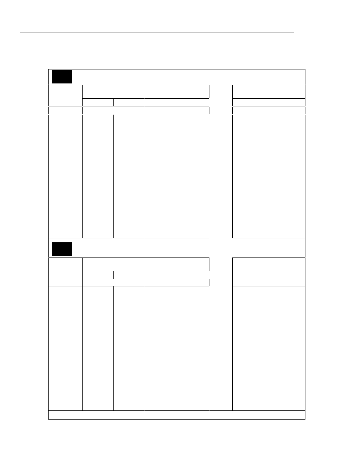
5700A/5720A Series II
Getting Started
Resistance Specifications
Table 10. 5720A Series II Resistance Specifications: 99 % and 95 % Confidence Levels
5720A
99%
99% Confidence Level
Nominal
Value
Ω±ppm ±ppm
0
1
1.9
10
19
100
190
1 k
1.9 k
10 k
19 k
100 k
190 k
1 M
1.9 M
10 M
19 M
100 M
Absolute Uncertainty of Characterized Value
±5 °C from calibration temperature [Note 1]
24 Hours 90 Days 180 Days 1 Year 24 Hours 90 Days
50 µΩ
85
85
23
23
10
10
8
8
8
9
9
9
16
17
33
43
100
50 µΩ
95
95
25
25
11
11
9
9
9
9
11
11
18
19
37
47
110
50 µΩ
100
100
26
26
11.5
11.5
9.5
9.5
9.5
9.5
12
12
20
21
40
50
115
50 µΩ
110
110
27
27
12
12
10
10
10
10
13
13
23
24
46
55
120
Relative Uncertainty
±1 °C
50 µΩ
32
25
5
4
2
2
2
2
2
2
2
2
2.5
3
10
20
50
50 µΩ
40
33
8
7
4
4
3
3
3
3
3
3
5
6
14
24
60
5720A
95%
95 % Confidence Level
Nominal
Value
Ω±ppm ±ppm
0
1
1.9
10
19
100
190
1 k
1.9 k
10 k
19 k
100 k
190 k
1 M
1.9 M
10 M
19 M
100 M
Note: 1. Specifications apply to displayed value. 4-wire connecti ons, except 100 MΩ.
Absolute Uncertainty of Characterized Value
±5 °C from calibration temperature [Note 1]
24 Hours 90 Days 180 Days 1 Year 24 Hours 90 Days
40 µΩ
70
70
20
20
8
8
6.5
6.5
6.5
7.5
7.5
7.5
13
14
27
35
85
40 µΩ
80
80
21
21
9
9
7.5
7.5
7.5
7.5
9
9
15
16
31
39
95
40 µΩ
85
85
22
22
9.5
9.5
8
8
8
8
10
10
17
18
34
42
100
40 µΩ
95
95
23
23
10
10
8.5
8.5
8.5
8.5
11
11
20
21
40
57
100
Relative Uncertainty
40 µΩ
27
20
4
3.5
1.6
1.6
1.6
1.6
1.6
1.6
1.6
1.6
2
2.5
8
16
40
±1 °C
40 µΩ
35
26
7
6
3.5
3.5
2.5
2.5
2.5
2.5
2.5
2.5
4
4
12
20
50
20
Page 35

Table 11. 5700A Series II Resistance Specifications: 99 % and 95 % Confidence Levels
5700A
99%
99 % Confidence Level
Nominal
Value
Ω±ppm ±ppm
0
1
1.9
10
19
100
190
1 k
1.9 k
10 k
19 k
100 k
190 k
1 M
1.9 M
10 M
19 M
100 M
Absolute Uncertainty of Characterized Value
±5 °C from calibration temperature [Note 1]
24 Hours 90 Days 180 Days 1 Year 24 Hours 90 Days
50 µΩ
85
85
26
24
15
15
11
11
9
9
11
11
16
17
33
43
110
50 µΩ
95
95
28
26
17
17
12
12
11
11
13
13
18
19
37
47
120
50 µΩ
100
100
30
28
18
18
13
13
12
12
14
14
20
21
40
50
125
50 µΩ
110
110
33
31
20
20
15
15
14
14
16
16
23
24
46
55
130
Relative Uncertainty
50 µΩ
32
25
5
4
2
2
2
2
2
2
2
2
2.5
3.5
10
20
50
Getting Started
Resistance Specifica tions
±1 °C
50 µΩ
40
33
8
7
4
4
3.5
3.5
3.5
3.5
3.5
3.5
5
6
14
24
60
5700A
95%
95 % Confidence Level
Nominal
Value
Ω±ppm ±ppm
0
1
1.9
10
19
100
190
1 k
1.9 k
10 k
19 k
100 k
190 k
1 M
1.9 M
10 M
19 M
100 M
Note: 1. Specifications apply to displayed value. 4-wire connecti ons, except 100 MΩ.
Absolute Uncertainty of Characterized Value
±5 °C from calibration temperature [Note 1]
24 Hours 90 Days 180 Days 1 Year 24 Hours 90 Days
50 µΩ
70
70
21
20
13
13
9
9
7.5
7.5
9
9
13
14
27
35
90
50 µΩ
80
80
23
22
14
14
10
10
9.5
9.5
11
11
15
16
31
39
100
50 µΩ
85
85
27
24
15
15
11
11
10.5
10.5
12
12
17
18
34
42
105
50 µΩ
95
95
28
27
17
17
13
13
12
12
14
14
20
21
40
47
110
Relative Uncertainty
50 µΩ
32
25
5
4
2
2
2
2
2
2
2
2
2.5
3
10
20
50
±1 °C
50 µΩ
40
33
8
7
4
4
3.5
3.5
3.5
3.5
3.5
3.5
5
6
14
24
60
21
Page 36

5700A/5720A Series II
µ
µ
µ
µ
µ
µ
µ
µ
µ
µ
µ
µ
µ
Getting Started
Table 12. Resistance Secondary Performance Specifications and Operating Characteristics
Nominal
Value
Ω±ppm ±ppm/°C mA mA ±ppm ±mΩ
0 008 - 500 500
13245008 - 100 700 500
1.9 25 6 7
10 5 2 3
19 4 2 3
100 2 2 3
190 2 2 3
1 k 2 2 3
1.9 k 2 2 3
Stability
±1 °C
[Note 1]
24 Hours 40 °-50 °C 0.1Ω 1Ω
Temperature
Coefficient Adder
[Note 2]
10 °-40 °C 0 °-10 °C
and
Full Spec
Load Range
[Note 3] to Nominal
Maximum
Peak
Current
Maximum
Difference
Characterized
Value
Two-Wire Adder
of
active
compensation
[Note 4]
Lead Resistance
µ
4 V
2 +
Im
4 +
4 V
00
8 - 100 500 500
00
8 - 11
00
8 - 11 160 300
00
8 - 11 70 150
00
8 - 11 50 150
00
1 - 2 22 150
00
1 - 1.5 16 150
220 300
2 +
Im
4 V
2 +
Im
4 V
2 +
Im
4 V
2 +
Im
4 V
2 +
Im
4 V
2 +
Im
10 15
10 15
4 +
4 +
4 +
4 +
4 +
4 +
4 V
Im
4 V
Im
4 V
Im
4 V
Im
4 V
Im
4 V
Im
4 V
Im
10 k 2 2 3 100 - 500 µA 7 150
19 k 2 2 3
100 k 2 2 3 10 - 100 µA 1 150 Im= Current
190 k 2 2 3 00 5 - 50 µA 500 µA 150
1 M 2.5 2.5 6 00 5 - 20 µA 100 µA 200
1.9 M 3.5 3 10 02.5 - 10 µA 50 µA 200
10 M 10 5 20 00.5 - 2 µA 10 µA 300
19 M 20 8 40 0.25 - 1 µA5 µA 300
100 M 50 12 100 0 50 - 200
0
50 - 250 µA 5 150
1 µA 500
nA
50 60
100 120
produced by
Ohmmeter
Notes:
1. Stability specifications are included in the Absolute Uncertainty values in the primary specification tables.
2. Temperature coefficient is an adder to uncertainty specifications that does not apply unless operated more
than 5 °C from calibration temperature, or calibrated outside the range 19 °C to 24 °C. Two examples:
• Calibrate at 20 °C: Temperature coefficient adder is not required unless operated below 15 °C or above
25 °C.
• Calibrate at 26 °C: Add 2 °C temperature coefficient adder. Additional temperature coefficient adder is
not required unless operated below 21 °C or above 31 °C.
3. Refer to current derating factors table for loads outside of this range.
4. Active two-wire compensation may be selected for values less than 100 kΩ, with either the front panel or the
meter input terminals as reference plane. Active compensation is limited to 11 mA load, and to 2 V burden.
Two-wire compensation can be used only with Ω-meters that source continuous (not pulsed) dc current.
22
Page 37

Table 13. Current Derating Factors
Nominal Value Value of Derating Factor K for Over or Under Current
Ω
SHORT
1
1.9
10
19
100
190
1 k
1.9 k
10 k
19 k
100 k
190 k
1 M
1.9 M
10 M
19 M
100 M
Two-Wire Comp
I < I
L
[Note 1]
4.4
4.4
4.4
4.4
4.4
4.4
4.4
4.4
4.4
5000
5000
Four-Wire
I < I
L
[Note 1]
0.3
300
160
30
16
3.5
2.5
0.4
0.4
50
50
7.5
4.0
1.0
0.53
0.2
0.53
0.1
Notes:
Getting Started
Resistance Specifica tions
Four-Wire
I
< I < I
U
max
[Note 2]
-5
4 x10
-4
1.5 x 10
-3
1.6 x 10
-3
3 x 10
-2
1 x 10
-2
1.9 x 10
0.1
0.19
2.0
3.8
-5
2 x 10
-5
3.8 x 10
-4
1.5 x 10
-4
2.9 x 10
-3
1 x 10
-3
1.9 x 10
I < I
1. For
, errors occur due to thermally generated voltages within the 5720A. Use the following
L
equation to determine the error, and add this error to the corresponding uncertainty or stability
specification.
Error = K(
Where: Error
four-w
2. For
I
- I)/( I
L
L
x I)
is in mΩ for all two-wire comp values and four-wire short, and in ppm for the remaining
ire values.
is the constant from the above table;
K
I and I
I and I
I
U
are expressed in mA for short to 1.9 kΩ;
L
are expressed in µA for 10 kΩ to 100 MΩ
L
< I < I
errors occur due to self-heating of the resistors in the calibrator. Use the following
MAX
equation to determine the error in ppm and add this error to the corresponding uncertainty or stability
specification.
2
Error
in ppm = K(I
2
-I
)
U
Where: K is the constant from the above table;
I and I
I and I
are expressed in mA for short to 19 kΩ;
U
are expressed in µA for 100 kΩ to 100 MΩ
U
23
Page 38

5700A/5720A Series II
Getting Started
DC Current Specifications
Table 14. 5720A Series II DC Current Specifications: 99 % and 95 % Confidence Levels
5720A
99%
99 % Confidence Level
Range Resolution
220 µA
2.2 mA
22 mA
220 mA
2.2 A
[Note 1]
11 A 10 330 + 470 340 + 480 350 + 480 360 + 480 100 + 130 110 + 130
Absolute Uncertainty
±5 °C from calibration temperature.
For fields strengths >0.4 V/m but ≤3 V/m,
24 Hours 90 Days 180 Days 1 Year 24 Hours 90 Days
nA ± (ppm output + nA) ± (ppm output + nA)
0.1
1
10
µA ± (ppm output + µA) ± (ppm output + µA)
0.1
1
040 + 7
030 + 8
030 + 50
040 + 0.8
060 + 15
5725A Amplifier:
add 1 % of range.
042 + 7
035 + 8
035 + 50
045 + 0.8
070 + 15
045 + 7
037 + 8
037 + 50
047 + 0.8
080 + 15
050 + 7
040 + 8
040 + 50
050 + 0.8
090 + 15
Relative Uncertainty ±1 °C
024 + 7
024 + 8
024 + 50
026 + 0.5
040 + 12
026 + 7
026 + 8
026 + 50
030 + 0.5
045 + 12
5720A
95%
95 % Confidence Level
Range Resolution
For fields strengths >0.4 V/m but ≤3 V/m,
24 Hours 90 Days 180 Days 1 Year 24 Hours 90 Days
nA ± (ppm output + nA) ± (ppm output + nA)
220 µA
2.2 mA
22 mA
220 mA
2.2 A
[Note 1]
11 A 10 330 + 470 340 + 480 350 + 480 360 + 480 100 + 130 110 + 130
Note: Maximum output from calibrator terminals is 2.2 A. Unce rtainty specifications for 220 mA and 2.2 mA ranges are
increased by a factor of 1.3 when supplied through 5725A terminals.
Specifications are otherwise identical for all out put l ocat i ons.
1. Add to uncertainty specifications:
±200 x I
±10 x I
0.1
1
10
µA ± (ppm output + µA) ± (ppm output + µA)
0.1
1
2
ppm for >100 mA on 220 mA range
2
ppm for >1 A on 2.2 A range
032 + 6
025 + 7
025 + 40
035 + 0.7
050 + 12
5725A Amplifier:
Absolute Uncertainty
±5 °C from calibration temperature
add 1 % of range.
035 + 6
030 + 7
030 + 40
040 + 0.7
060 + 12
037 + 6
033 + 7
033 + 40
042 + 0.7
070 + 12
045 + 0.7
080 + 12
040 + 6
035 + 7
035 + 40
Relative Uncertainty ±1 °C
020 + 6
020 + 7
020 + 40
020 + 0.7
032 + 12
022 + 6
022 + 7
022 + 40
025 + 0.7
040 + 12
24
Page 39

DC Current Specifications
Table 15. 5700A Series II DC Current Specifications: 99 % and 95 % Confidence Levels
5700A
99%
99 % Confidence Level
Absolute Uncertainty
±5 °C from calibration temperature
Range Resolution
nA ± (ppm output + nA) ± (ppm output + nA)
220 µA
2.2 mA
22 mA
220 mA
2.2 A
[Note 1]
5725A Amplifier:
11 A 10 330 + 470 340 + 480 350 + 480 360 + 480 100 + 130 110 + 130
0.1
1
10
µA ± (ppm output + µA) ± (ppm output + µA)
0.1
1
For fields strengths >0.4 V/m but ≤3 V/m,
24 Hours 90 Days 180 Days 1 Year 24 Hours 90 Days
045 + 10
045 + 10
045 + 100
055 + 1
075 + 30
add 1% of range.
050 + 10
050 + 10
050 + 100
060 + 1
080 + 30
055 + 10
055 + 10
055 + 100
065 + 1
090 + 30
060 + 10
060 + 10
060 + 100
070 + 1
095 + 30
Relative Uncertainty ±1 °C
024 + 2
024 + 5
024 + 50
026 + .3
040 + 7
026 + 2
026 + 5
026 + 50
030 + .3
045 + 7
Getting Started
5700A
95%
95 % Confidence Level
Absolute Uncertainty
Range Resolution
nA
220 µA
2.2 mA
22 mA
220 mA
2.2 A
[Note 1]
5725A Amplifier:
11 A 10 330 + 470 340 + 480 350 + 480 360 + 480 100 + 130 110 + 130
Note: Maximum output from the calibrator’s terminals is 2.2 A. Uncertainty specifications for 220 mA and 2.2 mA ranges
are increased by a factor of 1.3 when supplied through 5725A terminals.
Specifications are otherwise identical for all out put l ocat i ons.
1. Add to uncertainty specifications:
±200 x I
±10 x I
0.1
1
10
µA ± (ppm output + µA) ± (ppm output + µA)
0.1
1
2
ppm for >100 mA on 220 mA range
2
ppm for >1A on 2.2A range
045 + 0.8
060 + 25
±5 °C from calibration temperature
For fields strengths >0.4 V/m but ≤3 V/m,
24 Hours 90 Days 180 Days 1 Year 24 Hours 90 Days
035 + 8
035 + 8
035 + 80
add 1 % of range.
± (ppm output + nA) ± (ppm output + nA)
040 + 8
040 + 8
040 + 80
050 + 0.8
065 + 25
045 + 8
045 + 8
045 + 80
055 + 0.8
075 + 25
050 + 8
050 + 8
050 + 80
060 + 0.8
080 + 25
Relative Uncertainty ±1 °C
020 + 1.6
020 + 4
020 + 80
022 + 0.25
035 + 6
022 + 1.6
022 + 4
022 + 80
025 + 0.25
040 + 6
25
Page 40

5700A/5720A Series II
Getting Started
Table 16. DC Current Secondary Performance Specifications and Operating Characteristics
Range Stability
220 µA
2.2 mA
22 mA
220 mA
2.2 A
5725A
11 A
Notes:
Maximum output from the calibrator’s terminals is 2.2 A. Uncertainty specifications for 220 mA and 2.2 mA
ranges are increased by a factor of 1.3 when supplied through 5725A terminals.
Temperature
Coefficient [Note 2]
±1 °C [Note 1]
24 Hours 40 °-50 °C [Note 4] pk-pk RMS
± (ppm output
+ nA)
05 + 1
05 + 5
05 + 50
08 + 300
09 + 7 µA
± (ppm output
+ µA)
25 + 100 20 + 75 30 + 120
10 °-40 °C 0 °-10 °C
and
± (ppm output + nA)/ °C ±nA/V Ω ppm output
1 + 0.40
1 + 2
1 + 20
1 + 200
1 + 2.5 µΑ
± (ppm output + µA)/
3 + 1
3 + 10
3 + 100
3 + 1 µA
3 + 10 µA
°C
Compliance
Limits
10
10
10
10
3 [Note 5]
4
Burden
Voltage
Adder
[Note 3]
0.2
0.2
10
100
2 µA
Maximum
Load for
Full
Accuracy
20k
2k
200
20
2
4 15 + 70 175
Bandwidth
0.1-10 Hz
ppm output
Noise
+ nA
06 + .9
06 + 5
06 + 50
09 + 300
12 + 1.5 µA
+ µA
Bandwidth
0 Hz-10 kHz
nA
10
10
50
500
20 µA
µA
1. Stability specifications are included in the Absolute Uncertainty values for the primary specifications.
2. Temperature coefficient is an adder to uncertainty specifications. It does not apply unless operating more
than ±5 °C from calibration temperature.
3. Burden voltage adder is an adder to uncertainty specifications that does not apply unless burden voltage is
greater than 0.5 V.
4. For higher loads, multiply uncertainty specification by:
1
+
0.1 x actual load
maximum load for full accuracy
5. The calibrator’s compliance limit is 2 V for outputs from 1 A to 2.2 A. 5725A Amplifier may be used in rangelock mode down to 0 A.
Minimum output: 0 for all ranges, including 5725A.
Settling time to full accuracy: 1 second for mA and mA ranges; 3 seconds for 2.2 A range; 6 seconds for 11
A range; + 1 second for range or polarity change
Overshoot: <5 %
26
Page 41

AC Current Specifications
Table 17. 5720A Series II AC Current Specifications: 99 % Confidence Level
5720A
99%
99 % Confidence Level
Range Resolution Frequency
For fields strengths >0.4 V/m but ≤3 V/m,
24 Hours 90 Days 180 Days 1 Year 24 Hours 90 Days
Hz ± (ppm output + nA) ± (ppm output + nA)
0260 + 20
0170 + 12
0120 + 10
0300 + 15
1000 + 80
0260 + 50
0170 + 40
0120 + 40
0210 + 130
1000 + 800
0260 + 500
0170 + 400
0120 + 400
0210 + 700
1000 + 6000
Hz ± (ppm output + µA) ± (ppm output + µA)
0260 + 5
0170 + 4
0120 + 3
0210 + 4
1000 + 12
0290 + 40
0440 + 100
6000 + 200
5725A Amplifier:
0370 + 170
0800 + 380
3000 + 750
220 µA1 nA
2.2 mA 10 nA
22 mA 100 nA
220 mA 1 µA
2.2 A 10 µA
11 A 100 µA
010 - 20
020 - 40
040 - 1 k
01k - 5 k
05k - 10 k
010 - 20
020 - 40
040 - 1 k
01k - 5 k
05k - 10 k
010 - 20
020 - 40
040 - 1 k
01k - 5 k
05k - 10 k
010 - 20
020 - 40
040 - 1 k
01k - 5 k
05k - 10 k
020 - 1 k
01 k - 5 k
05 k - 10 k
040 - 1 k
01 k - 5 k
05 k - 10 k
Absolute Uncertainty
±5 °C from calibration temperature
add 1 % of range.
0280 + 20
0180 + 12
0130 + 10
0320 + 15
1100 + 80
0280 + 50
0180 + 40
0130 + 40
0220 + 130
1100 + 800
0280 + 500
0180 + 400
0130 + 400
0220 + 700
1100 + 6000
0280 + 5
0180 + 4
0130 + 3
0220 + 4
1100 + 12
0300 + 40
0460 + 100
7000 + 200
0400 + 170
0850 + 380
3300 + 750
0290 + 20
0190 + 12
0135 + 10
0340 + 15
1200 + 80
0290 + 50
0190 + 40
0135 + 40
0230 + 130
1200 + 800
0290 + 500
0190 + 400
0135 + 400
0230 + 700
1200 + 6000
0290 + 5
0190 + 4
0135 + 3
0230 + 4
1200 + 12
0310 + 40
0480 + 100
7500 + 200
0440 + 170
0900 + 380
3500 + 750
0300 + 20
0200 + 12
0140 + 10
0350 + 15
1300 + 80
0300 + 50
0200 + 40
0140 + 40
0240 + 130
1300 + 800
0300 + 500
0200 + 400
0140 + 400
0240 + 700
1300 + 6000
0300 + 5
0200 + 4
0140 + 3
0240 + 4
1300 + 12
0320 + 40
0500 + 100
8000 + 200
0460 + 170
0950 + 380
3600 + 750
Getting Started
AC Current Specifications
Relative Uncertainty
±1 °C
0260 + 20
0130 + 12
0100 + 10
0250 + 15
0900 + 80
0260 + 50
0130 + 40
0100 + 40
0250 + 130
0900 + 800
0260 + 500
0130 + 400
0100 + 400
0250 + 700
0900 + 6000
0260 + 5
0130 + 4
0100 + 3
0250 + 4
0900 + 12
0300 + 40
0500 + 100
6000 + 200
0300 + 170
0700 + 380
2800 + 750
0280 + 20
0150 + 12
0110 + 10
0280 + 15
01000 + 80
0280 + 50
0150 + 40
0110 + 40
0280 + 130
1000 + 800
0280 + 500
0150 + 400
0110 + 400
0280 + 700
1000 + 6000
0280 + 5
0150 + 4
0110 + 3
0280 + 4
1000 + 12
0350 + 40
0520 + 100
7000 + 200
0330 + 170
0800 + 380
3200 + 750
Note: Maximum output from the calibrator’s terminals is 2.2 A. Uncertainty specifications for 220 µA and 2.2 mA
ranges are increased by a factor of 1.3 plus 2 µA when supplied through 5725A terminals. Specifications are
otherwise identical for all output locations.
27
Page 42

5700A/5720A Series II
Getting Started
5720A
95%
95 % Confidence Level
Range Resolution Frequency
220 µA1 nA
2.2 mA 10 nA
22 mA 100 nA
220
mA
2.2 A 10 µA
11 A 100 µA
Note: Maximum output from the calibrator’s terminals is 2.2 A. Uncertainty specifications for 220 µA and
2.2 mA ranges are increased by 1.3 x plus 2 µA when supplied through 5725A terminals. Specifications are
otherwise identical for all output locations.
1 µA
Table 18. 5720A Series II AC Current Specifications: 95 % Confidence Level
Absolute Uncertainty
±5 °C from calibration temperature
For fields strengths >0.4 V/m but ≤3 V/m,
add 1 % of range.
24 Hours 90 Days 180 Days 1 Year 24 Hours 90 Days
Hz ± (ppm output + nA) ± (ppm output + nA)
010 - 20
020 - 40
040 - 1 k
01 k - 5 k
05 k - 10 k
010 - 20
020 - 40
040 - 1 k
01 k - 5 k
05 k - 10 k
010 - 20
020 - 40
040 - 1 k
01 k - 5 k
05 k - 10 k
0210 + 16
0130 + 10
0100 + 8
0240 + 12
0800 + 65
0210 + 40
0140 + 35
0100 + 35
0170 + 110
0800 + 650
0210 + 400
0130 + 350
0100 + 350
0170 + 550
0800 + 5000
0230 + 16
0140 + 10
0110 + 8
0250 + 12
0900 + 65
0230 + 40
0140 + 35
0110 + 35
0180 + 110
0900 + 650
0230 + 400
0140 + 350
0110 + 350
0180 + 550
0900 + 5000
0240 + 16
0150 + 10
0115 + 8
0270 + 12
1000 + 65
0240 + 40
0150 + 35
0115 + 35
0190 + 110
1000 + 650
0240 + 400
0150 + 350
0115 + 350
0190 + 550
1000 + 5000
0250 + 16
0160 + 10
0120 + 8
0280 + 12
1100 + 65
0250 + 40
0160 + 35
0120 + 35
0200 + 110
1100 + 650
0250 + 400
0160 + 350
0120 + 350
0200 + 550
1100 + 5000
Hz ± (ppm output + µA) ± (ppm output + µA)
010 - 20
020 - 40
040 - 1 k
01 k - 5 k
05 k - 10 k
020 - 1 k
01 k - 5 k
05 k - 10 k
0210 + 4
0130 + 3.5
0100 + 2.5
0170 + 3.5
0800 + 10
0230 + 35
0350 + 80
5000 + 160
0230 + 4
0140 + 3.5
0110 + 2.5
0180 + 3.5
0900 + 10
0240 + 35
0390 + 80
6000 + 160
0240 + 4
0150 + 3.5
0115 + 2.5
0190 + 3.5
1000 + 10
0250 + 35
0420 + 80
6500 + 160
0250 + 4
0160 + 3.5
0120 + 2.5
0200 + 3.5
1100 + 10
0260 + 35
0450 + 80
7000 + 160
5725A Amplifier:
040 - 1 k
01 k - 5 k
05 k - 10 k
0370 + 170
0800 + 380
3000 + 750
0400 + 170
0850 + 380
3300 + 750
0440 + 170
0900 + 380
3500 + 750
0460 + 170
0950 + 380
3600 + 750
Relative Uncertainty
0210 + 16
0110 + 10
0080 + 8
0200 + 12
0700 + 65
0210 + 40
0110 + 35
0080 + 35
0200 + 110
0700 + 650
0210 + 400
0110 + 350
0080 + 350
0200 + 550
0700 + 5000
0210 + 4
0110 + 3.5
0080 + 2.5
0200 + 3.5
0700 + 10
0250 + 35
0400 + 80
5000 + 160
0300 + 170
0700 + 380
2800 + 750
±1 °C
0230 + 16
0130 + 10
0090 + 8
0230 + 12
0800 + 65
0230 + 40
0130 + 35
0090 + 35
0230 + 110
0800 + 650
0230 + 400
0130 + 350
0090 + 350
0230 + 550
0800 + 5000
0230 + 4
0130 + 3.5
090 + 2.5
0230 + 3.5
0800 + 10
0300 + 35
0440 + 80
6000 + 160
0330 + 170
0800 + 380
3200 + 750
28
Page 43

5700A
99%
Getting Started
AC Current Specifications
Table 19. 5700A Series II AC Current Specifications: 99 % Confidence Level
99 % Confidence Level
Absolute Uncertainty
Range Resolution Frequency
±5 °C from calibration temperature
Relative Uncertainty
±1 °C
For fields strengths >0.4 V/m but ≤3 V/m,
add 1 % of range.
24 Hours 90 Days 180 Days 1 Year 24 Hours 90 Days
Hz ± (ppm output + nA) ± (ppm output + nA)
010 - 20
020 - 40
220 µA1 nA
2.2 mA 10 nA
22 mA 100 nA
040 - 1 k
01 k - 5 k
05 k - 10 k
010 - 20
020 - 40
040 - 1 k
01 k - 5 k
05 k - 10 k
010 - 20
020 - 40
040 - 1 k
01 k - 5 k
05 k - 10 k
0650 + 30
0350 + 25
0120 + 20
0500 + 50
1500 + 100
0650 + 50
0350 + 40
0120 + 40
0500 + 500
1500 + 1000
0650 + 500
0350 + 400
0120 + 400
0500 + 5000
1500 + 10,000
0700 + 30
0380 + 25
0140 + 20
0600 + 50
1600 + 100
0700 + 50
0380 + 40
0140 + 40
0600 + 500
1600 + 1000
0700 + 500
0380 + 400
0140 + 400
0600 + 5000
1600 + 10,000
0750 + 30
0410 + 25
0150 + 20
0650 + 50
1700 + 100
0750 + 50
0410 + 40
0150 + 40
0650 + 500
1700 + 1000
0750 + 500
0410 + 400
0150 + 400
0650 + 5000
1700 + 10,000
00 800 + 30
00 420 + 25
00 160 + 20
00 700 + 50
0 1800 + 100
00 800 + 50
0 0420 + 40
00 160 + 40
00 700 + 500
0 1800 + 1000
00 800 + 500
00 420 + 400
00 160 + 400
00 700 + 5000
0 1800 + 10,000
0450 + 30
0270 + 25
0110 + 20
0450 + 50
1400 + 100
0450 + 50
0270 + 40
0110 + 40
0450 + 500
1400 + 1000
0450 + 500
0270 + 400
0110 + 400
0450 + 5000
1400 + 10,000
0500 + 30
0300 + 25
0120 + 20
0500 + 50
1500 + 100
0500 + 50
0300 + 40
0120 + 40
0500 + 500
1500 + 1000
0500 + 500
0300 + 400
0120 + 400
0500 + 5000
1500 + 10,000
Hz ± (ppm output + µA) ± (ppm output + µA)
220 mA 1 µA
2.2 A 10 µA
010 - 20
020 - 40
040 - 1 k
01 k - 5 k
5 k - 10 k
20 - 1 k
1 k - 5 k
5 k - 10 k
0650 + 5
0350 + 4
0120 + 4
0500 + 50
1500 + 100
0600 + 40
0700 + 100
8000 + 200
0700 + 5
0380 + 4
0150 + 4
0600 + 50
1600 + 100
0650 + 40
0750 + 100
9000 + 200
0750 + 5
0410 + 4
0170 + 4
0650 + 50
1700 + 100
0700 + 40
0800 + 100
9500 + 200
00 800 + 5
00 420 + 4
00 180 + 4
0 700 + 50
0 1800 + 100
0 750 + 40
00 850 + 100
10,000 + 200
0450 + 5
0280 + 4
0110 + 4
0450 + 50
1400 + 100
0600 + 40
0650 + 100
7500 + 200
0500 + 5
0300 + 4
0130 + 4
0500 + 50
1500 + 100
0650 + 40
0750 + 100
8500 + 200
5725A Amplifier:
11 A 100 µA
40 - 1 k
1 k - 5 k
5 k - 10 k
0370 + 170
0800 + 380
3000 + 750
400 + 170
850 + 380
3300 + 750
0440 + 170
0900 + 380
3500 + 750
00 460 + 170
00 950 + 380
0 3600 + 750
0300 + 170
0700 + 380
2800 + 750
0330 + 170
0800 + 380
3200 + 750
Note: Maximum output from the calibrator’s terminals is 2.2 A. Uncertainty specifications for 220 µA and 2.2 mA
ranges are increased by 1.3 x plus 2 µA when supplied through 5725A terminals. Specifications are otherwise
identical for all output locations.
29
Page 44

5700A/5720A Series II
Getting Started
5700A
95%
Table 20. 5700A Series II AC Current Specifications: 95 % Confidence Level
95 % Confidence Level
Range Resolution Frequency
±5 °C from calibration temperature
For fields strengths >0.4 V/m but ≤3 V/m,
Relative Uncertainty
±1 °C
add 1 % of range.
24 Hours 90 Days 180 Days 1 Year 24 Hours 90 Days
Hz ± (ppm output + nA) ± (ppm output + nA)
Absolute Uncertainty
010 - 20
020 - 40
220 µA1 nA
2.2 mA 10 nA
22 mA 100 nA
040 - 1 k
01 k - 5 k
05 k - 10 k
010 - 20
020 - 40
040 - 1 k
01 k - 5 k
05 k - 10 k
010 - 20
020 - 40
040 - 1 k
01 k - 5 k
05 k - 10 k
0550 + 25
0280 + 20
0100 + 16
0400 + 40
1300 + 80
0550 + 40
0280 + 35
0100 + 35
0400 + 400
1300 + 800
0550 + 400
0280 + 350
0100 + 350
0400 + 4000
1300 + 8000
0600 + 25
0310 + 20
0120 + 16
0500 + 40
1400 + 80
0600 + 40
0310 + 35
0120 + 35
0500 + 400
1400 + 800
0600 + 400
0310 + 350
0120 + 350
0500 + 4000
1400 + 8000
0650 + 25
0330 + 20
0130 + 16
0550 + 40
1500 + 80
0650 + 40
0330 + 35
0130 + 35
0550 + 400
1500 + 800
0650 + 400
0330 + 350
0130 + 350
0550 + 4000
1500 + 8000
0700 + 25
0350 + 20
0140 + 16
0600 + 40
1600 + 80
0700 + 40
0350 + 35
0140 + 35
0600 + 400
1600 + 800
0700 + 400
0350 + 350
0140 + 350
0600 + 4000
1600 + 8000
0375 + 25
0220 + 20
090 + 16
0375 + 40
1200 + 80
0375 + 40
0220 + 35
0090 + 35
0375 + 400
1200 + 800
0375 + 400
0220 + 350
0090 + 350
0375 + 4000
1200 + 8000
0400 + 25
0250 + 20
0100 + 16
0400 + 40
1200 +80
0400 + 40
0250 + 35
0100 + 35
0400 + 400
1200 + 800
0400 + 400
0250 + 350
0100 + 350
0400 + 4000
1200 + 8000
Hz ± (ppm output + µA) ± (ppm output + µA)
220 mA 1 µA
2.2 A 10 µA
010 - 20
020 - 40
040 - 1 k
01k - 5 k
5k - 10 k
20 - 1 k
1 k - 5 k
5 k - 10 k
0550 + 4
0280 + 3.5
0100 + 3.5
0400 + 40
1300 + 80
0500 + 35
0600 + 80
6500 + 160
0600 + 4
0310 + 3.5
0120 + 3.5
0500 + 40
1400 + 80
0550 + 35
0650 + 80
7500 + 160
0650 + 4
0330 + 3.5
0130 + 3.5
0550 + 40
1500 + 80
0600 + 35
0700 + 80
8000 + 1600
0700 + 4
0350 + 3.5
0140 + 3.5
0600 + 40
1600 + 80
0650 + 35
0750 + 80
8500 + 160
0375 + 4
0220 + 3.5
0090 + 3.5
0375 + 40
1200 + 80
0500 + 35
0550 + 80
6000 + 160
0400 + 4
0250 + 3.5
0100 + 3.5
0400 + 40
1200 + 80
0550 + 35
0650 + 80
7000 + 160
5725A Amplifier:
11 A 100 µA
40 - 1 k
1 k - 5 k
5 k - 10 k
0370 + 170
0800 + 380
3000 + 750
0400 + 170
0850 + 380
3300 + 750
0440 + 170
0900 + 380
3500 + 750
0460 + 170
0950 + 380
3600 + 750
0300 + 170
0700 + 380
2800 + 750
0330 + 170
0800 + 380
3200 + 750
Note: Maximum output from the calibrator’s terminals is 2.2 A. Uncertainty specifications for 220 µA and
2.2 mA ranges are increased by a factor of 1.3 plus 2 µA when supplied through 5725A terminals. Specifications
are otherwise identical for all output locations.
30
Page 45

Getting Started
AC Current Specifications
Table 21. AC Current Secondary Performance Specifications and Operating Characteristics
Stability
±1 °C [Note 1]
Range Frequency 24 Hours 10°-40 °C 0°-10 °C and
Hz ± (ppm output + nA) ± (ppm output + nA)/°C V rms Ω± (% output + µA)
220 µA 010 - 20
020 - 40
040 - 1 k
01 k - 5 k
05 k - 10 k
2.2 mA 010 - 20
020 - 40
040 - 1 k
01 k - 5 k
05 k - 10 k
22 mA
220 mA 010 - 20
2.2 A 20 - 1 k
5725A Amplifier: ± (% output)
Notes:
Maximum output from 5720A terminals is 2.2 A. Uncertainty speci fications for 220 µA and 2.2 mA ranges are increased by a
factor of 1.3, plus 2 µA when supplied through 5725A terminals. Specifications are otherwise identical for all output locat i ons.
1. Stability specifications are included in the Absolute Uncertainty values for the primary specifications.
2. Temperature coefficient is an adder to uncertainty specifications that does not apply unless operating more than ±5 °C from
3. For larger resistive loads multiply uncertainty specifi cations by:
4. 1.5 V compliance limit above 1 A. 5725A Amplifier may be used in range-lock mode down to 1 A.
5. For resistive loads within rated compliance voltage limits.
6. For outputs from the Aux Current terminals, the maximum res ist i ve load for full accuracy is 1 kΩ. For larger resistive loads,
Minimum output: 9 µA for 220 µA range, 10 % on all other ranges. 1 A minimum for 5725A.
Inductive load limits: 400 µH (5700A/5720A, or 5725A). 20 µH for 5700A/5720A output >1 A.
Power factors: 5700A/5720A, 0.9 to 1; 5725A, 0.1 to 1. Subject to compliance voltage limits.
Frequency:
Range (Hz): 10.000-11.999, 12.00-119.99, 120.0-1199.9, 1.200 k-10.000 k
Uncertainty: ±0.01 %
Resolution: 11,999 counts
Settling time to full accuracy: 5 seconds for 5700A/5720A ranges; 6 seconds for 5725A 11 A range; +1 second for
amplitude or frequency range change.
Overshoot: <10 %
010 - 20
020 - 40
040 - 1 k
01 k - 5 k
05 k - 10 k
Hz ± (ppmutput + µA) ± (ppm output + µA)/°C
020 - 40
040 - 1 k
01 k - 5 k
05 k - 10 k
1 k - 5 k
5 k - 10 k
11 A 40 - 1 k
1 k - 5 k
5 k - 10 k
calibration temperature.
multiply the uncertainty as described in Note 3.
150 + 5
080 + 5
030 + 3
050 + 20
400 + 100
150 + 5
080 + 5
030 + 3
050 + 20
400 + 100
150 + 50
080 + 50
030 + 30
050 + 500
400 + 1000
150 + 0.5
080 + 0.5
030 + 0.3
050 + 3
400 + 5
050 + 5
080 + 20
800 + 50
075 + 100
100 + 150
200 + 300
Temperature Coefficient
[Note 2]
40°-50 °C
050 + 5
020 + 5
004 + 0.5
010 + 1
020 + 100
050 + 5
020 + 4
004 + 1
010 + 100
050 + 400
050 + 10
020 + 10
004 + 10
010 + 500
050 + 1000
050 + 0.05
020 + 0.05
004 + 0.1
010 + 2
050 + 5
004 + 1
010 + 5
050 + 10
020 + 75
040 + 75
100 + 75
050 + 5
020 + 5
010 + 0.5
020 + 1
020 + 100
050 + 5
020 + 4
010 + 2
020 + 100
050 + 400
050 + 10
020 + 10
010 + 20
020 + 400
050 + 1000
050 + 0.05
020 + 0.05
010 + 0.1
020 + 2
050 + 5
010 + 1
020 + 5
050 + 10
030 + 75
050 + 75
100 + 75
(
maximum load for full accuracy
Compliance
Limits
72k
7 500 0.05 + 0.1
7 150 0.05 + 0.1
7 15 0.05 + 10
1.4
[Note 4]
3 3 0.05
actual load
Maximum
Resistive
Load
For Full
Accuracy
[Note 3]
[Note 6]
0.5 0.5 + 100
2
)
Noise and
Distortion
Bandwidth
10 Hz-50 kHz
<0.5V Burden
0.05 + 0.1
0.05 + 0.1
0.05 + 0.1
0.25 + 0.5
00.5 + 1
0.05 + 0.1
0.05 + 0.1
0.25 + 0.5
00.5 + 1
0.05 + 0.1
0.05 + 0.1
0.25 + 0.5
00.5 + 1
0.05 + 10
0.05 + 10
0.25 + 50
00.5 + 100
0.3 + 500
0 1 + 1 mA
0.12
0.5
[Note 5]
31
Page 46

5700A/5720A Series II
Getting Started
Wideband AC Voltage (Option 5 700-03) Specifications
Specifications apply to the end of the cable and 50 Ω termination used for calibration
Volts dBm 24 Hours 90 Days 180 Days 1 Year
1.1 mV -46 10 nV 0.4 + 0.4 00.5 + 0.4 00.6 + 0.4 0.8 + 2
3 mV -37 10 nV 0.4 + 1 0.45 + 1 00.5 + 1 0.7 + 3
11 mV -26 100 nV 0.2 + 4 0.35 + 4 00.5 + 4 0.7 + 8
33 mV -17 100 nV 0.2 + 10 00.3 + 10 0.45 + 10 0.6 + 16
110 mV -6.2 1 µV 0.2 + 40 00.3 + 40 0.45 + 40 0.6 + 40
330 mV +3.4 1 µV 0.2 + 100 0 2. 5 + 100 0. 35 + 100 0.5 + 100
1.1 V +14 10 µV 0.2 + 400 0.25 + 400 0.35 + 400 0.5 + 400
3.5 V +24 10 µV 0.15 + 500 00.2 + 500 00.3 + 500 0.4 + 500
Table 22. Wideband AC Voltage (Option 5700-03) Specifications
Range Resolution
Absolute Uncertainty
±5 °C from calibration temperature
± (% output + µV)
30 Hz-500 kHz
Settling
Frequency Frequency
Hz Hz ± (% output + floor indicated) ±ppm/°C Seconds dB
00 10 - 30 0.01 0.3 0.3 0.3 100 7 -40
00 30 - 120 0.01 0.1 0.1 0.1 100 7 -40
0 120 - 1.2 k 0.1 0.1 0.1 0.1 100 5 -40
01.2 k - 12 k 1 0.1 0.1 0.1 100 5 -40
0 12 k - 120 k 10 0.1 0. 1 0.1 100 5 -40
120 k - 1.2 M 100 00.2 + 3 µV 00.1 + 3 µV 0.1 + 3 µV 100 5 -40
1.2 M - 2 M 100 k 00.2 + 3 µV 00.1 + 3 µV 0.1 + 3 µV 100 0.5 -40
0 2 M - 10 M 100 k 00.4 + 3 µV 00.3 + 3 µV 0.2 + 3 µV 100 0.5 -40
10 M - 20 M 1 M 00.6 + 3 µV 00.5 + 3 µV 0.4 + 3 µV 150 0.5 -34
20 M - 30 M 1 M 10.5 + 15 µV 10.5 + 3 µV 0 1 + 3 µV 300 0.5 -34
Additional Operating Information:
dBm reference = 50 Ω
Range boundaries are at voltage points, dBm levels are approximate.
dBm = 10 log
Minimum output: 300 µV (-57 dBm)
Frequency uncertainty: ±0.01 %
Frequency resolution: 11,999 counts to 1.1999 MHz, 119 counts to 30 MHz.
Overload protection: A short circuit on the wideband output will not result in damage. After settli ng time, normal operation
is restored upon removal.
Resolution
Power
(
1 mW
) ; 0.22361 V across 50 Ω = 1 mW or 0 dBm
Amplitude Flatness, 1 kHz Reference
Voltage Range
1.1 mV 3 mV >3 mV
Temperature
Coefficient
Time To
Full
Accuracy
Harmonic
Distortion
32
Page 47

General Specifications
General Specif ications
Warm-Up Time: Twice the time since last warmed up, to a maximum of 30 minutes.
System installation: Rear output configuration and rack- mount kit available.
Standard interfaces: IEEE-488, RS-232, 5725A, 5205A or 5215A, 5220A, phase lock in (BNC), phase
reference out (BNC).
Temperature performance: Operating: 0 °C to 50 °C. Calibration: 15 °C to 35 °C. Storage: -40 °C to
75 °C; DC Zeros calibration required every 30 days.
Relative humidity: Operating: <80 % to 30 °C, <70 % to 40 °C, <40 % to 50 °C. Storage: <95 %, noncondensing. A power stabilization period of four days may be required after extended storage at high
temperature and humidity.
Safety: Designed to comply with UL3111; EN61010; CSA C22.2 No. 1010; ANSI/ISA S82.01-1994
Guard isolation: 20 V
EMI/RFI: Designed to comply with FCC Rules Part 15, Subpart B, Class B; EN50081-1, EN50082-1
Electro Static Discharge: This instrument meets criteria C for ESD requirements per EN61326
Line Power: 47 to 63 Hz; ±10 % allowed about selectable nominal line voltage: 100 V, 110 V, 115 V,
120 V, 200 V, 220 V, 230 V, 240 V. Maximum power: 5700A/5720A, 300 VA; 5725A, 750 VA.
Getting Started
Size:
5700A/5720A: Height 17.8 cm (7 in), standard rack increment, plus 1.5 cm (0.6 in) for feet; Width 43.2 cm
(17 in), standard rack width; Depth 63.0 cm (24.8 in), overall; 57.8 cm (22.7 in), rack depth.
5725A: Height 13.3 cm, (5.25 in); Width and depth same as 5700A/5720A. Both units project 5.1 cm, (2
in) from rack front.
Weight: 5700A/5720A: 27kg (62 lbs); 5725A: 32kg (70 lbs).
43.2 cm (17 in)
17.8 cm (7 in)
63 cm (24.8 in)
6.35 cm (2.5 in)
FOR CABLE
ACCESS
33
Page 48

5700A/5720A Series II
Getting Started
Auxiliary Amplifier Specifications
For complete specifications, see the 5205A and 5220A Operators Manuals.
5205A (220V - 1100 V ac, 0 V - 1100 V dc)
Overshoot: < 10 %
Distortion (bandwidth 10 Hz - 1 MHz):
10 Hz - 20 kHz
20 kHz - 50 kHz
50 kHz - 100 kHz
Frequency
(Hz)
0.07 %
0.2 %
0.25 %
90 Day Accuracy
at 23° ±5 °C
± (% output + % range)
Temperature Coefficient for
0°-18 °C and 28°-50 °C
± (ppm output + ppm range)/ °C
00 dc
010 - 40
040 - 20 k
20 k - 50 k
50 k - 100 k
0.05 + 0.005
0.15 + 0.005
0.04 + 0.004
0.08 + 0.006
00.1 + 0.01
5220A (AC Current, 180-day specifications):
Accuracy:
20 Hz - 1 kHz
1 kHz - 5 kHz
Temperature Coefficient (0° - 18 °C and 28° - 50 °C): (0.003 % + 100 µA)/°C
Distortion (bandwidth 300 kHz):
20 Hz - 1 kHz
1 kHz - 5 kHz
Note: 5700A/5720A combined with 5220A is not specified for inductive loads.
0.07% + 1 mA
(0.07% + 1mA) x frequency in kHz
0.1% + 1 mA
(0.1% + 1 mA) x frequency in kHz
15 + 3
45 + 3
15 + 3
50 + 10
70 + 20
34
Page 49

Unpacking and Inspection
The calibrator is shipped in a container designed to prevent damage during shipping.
Inspect the calibrator carefully for damage, and immediately report any damage to the
shipper. Instructions for inspection and claims are included in the shipping container.
When you unpack the calibrator, check for all the standard equipment listed in Table
and check the shipping order for any additional items ordered. Refer to Chapter 8 of the
Operators Manual for information about options and accessories. Report any shortage
to the place of purchase or to the nearest Fluke Service Center. If performance tests are
required for your acceptance procedures, refer to the 5700A/5720A Series II Service
Manual for instructions.
If you need to reship the calibrator, use the original container. If it is not available, you
can order a new container from Fluke by indicating the calibrator’s model and serial
number.
Table 23. Standard Equipment
Item Model or Part Number
Calibrator 5700A/5720A Series II
Getting Started
Unpacking and Inspection
Line Power Cord See Table and Figure
5700A/5720A Series II Manual Set 1668111
5700A/5720A Series II Operators Reference
Guide
5700A/5720A Series II Remote Programming
Reference Guide
5700A/5720A Series II Getting Started 1668111
5700A/5720A Series II Manual CD 1668127
Certificate of Calibration No part number
601648
601655
Service Information
Each calibrator is warranted to the original purchaser for a period of one year beginning
on the date received. The warranty is located at the front of this manual.
Service and technical advice for the calibrator is available at Fluke Service Centers. For
a complete list of Fluke Service Centers, visit www.fluke.com.
After-warranty service is available, but you may choose to repair the calibrator using
the information in the Troubleshooting Chapter of the 5700A/5720A Series II Service
Manual and the Module Exchange Program. Refer to the Fluke catalog or contact a
Service Center representative for the module exchange procedure.
35
Page 50

5700A/5720A Series II
Getting Started
Contacting Fluke
To order accessories, receive operating assistance, or get the location of the nearest
Fluke distributor or Service Center, call:
USA: 1-888-99-FLUKE (1-888-993-5853)
Canada: 1-800-36-FLUKE (1-800-363-5853)
Europe: +31 402-678-200
Japan: +81-3-3434-0181
Singapore: +65-738-5655
Anywhere in the world: +1-425-446-5500
Or, visit Fluke’s Web site at www.fluke.com.
Placement and Rack Mounting
Place the calibrator on top of a bench or mounted in a standard-width, 24-inch (61-cm)
deep equipment rack. For bench-top use, the calibrator is equipped with non-slipping,
non-marring feet. To mount the calibrator in an equipment rack, use the Rack Mount
Kit, Model Y-5737, instructions are included with the kit. For convenience, the rack
mount instruction sheet can be stored in the binder of this manual.
Cooling Considerations
Damage caused by overheating may occur if the area around
the air intake is restricted, the intake air is too warm, or the air
filter becomes clogged.
A hidden but important feature of the calibrator is its internal cooling system. Baffles
direct cooling air from the fans throughout the chassis to internally dissipate heat
during operation. The accuracy and dependability of all internal parts of the calibrator
are enhanced by maintaining the coolest possible internal temperature. By observing
the following rules, you can lengthen the life of the calibrator and enhance its
performance:
• The area around the air filter must be at least 3 inches from nearby walls or rack
enclosures.
• The exhaust perforations on the sides of the calibrator must be clear of
obstructions.
• The air entering the instrument must be room temperature. Make sure that exhaust
from another instrument is not directed into the fan inlet.
• Clean the air filter every 30 days or more frequently if the calibrator is operated in
a dusty environment. (Instructions for cleaning the air filter are in Chapter 7 of the
Operators Manual.)
Caution
36
Page 51

Accessing the Fuse
To prevent instrument damage, verify that the correct fuse is
installed for the line voltage setting.
The line power fuse is accessible on the rear panel. The fuse rating label to the right of
the fuse holder (labeled F1) shows the correct rep laceme n t fus e rating for each li ne
voltage setting. To check or replace the fuse, refer to Figure 3 and proceed as follows:
1. Disconnect line power.
2. Using a standard screwdriver, loosen the fuse holder by turning the slot labeled F1
until the cap and fuse pop free.
3. Replace the fuse and holder.
Getting Started
Accessing the Fuse
Caution
CHASSIS
GROUND
S2 S3 S4
!
FUSE -F1
SELECTION
100V
110V
115V
120V
VOLTAGE
S2 S3 S4
FUSE-F1
T 125A
250V
(SB)
200V
220V
230V
240V
VOLTAGE
SELECTION
S2 S3 S4
FUSE-F1
T 125A
250V
(SB)
Figure 3. Accessing the Fuse
alh2.eps
37
Page 52

5700A/5720A Series II
Getting Started
Selecting Line Voltage
The calibrator arrives from the factory configured for the line voltage normally
appropriate for the country of purchase, or as specified at the time of your purchase
order. The calibrator also comes with the appropriate line power plug for the country of
purchase. If you need a different type, refer to Table 24 and Figure 4. They list and
illustrate the line power plug types available from Fluke.
Check the line power label on the rear panel of the calibrator to verify that the line
voltage matches local line power. Figure 5 shows the location of the line power label.
You can set the calibrator to operate from eight different nominal line voltages; each
voltage setting has a voltage tolerance of ± 10%, and frequency range of 47 to 63 Hz.
The line voltage switches are located on the bottom left side of the rear panel.
To change the line voltage setting, set the line voltage selection switches to the correct
setting shown in Figure 5.
Type Voltage/Current Fluke Option Number
North America 120V/15A LC-1
Table 24. Line Power Cord Types Available from Fluke
North America 240V/15A LC-2
Universal Euro 220V/16A LC-3
United Kingdom 240V/13A LC-4
Switzerland 220V/10A LC-5
Australia 240V/10A LC-6
South Africa 240V/5A LC-7
LC-1 LC-2 LC-3 LC-4
38
LC-5 LC-6 LC-7
alh3.eps
Figure 4. Line Power Cord Types Available from Fluke
Page 53

Getting Started
Selecting Line Voltage
VOLTAGE
SELECTION
S2 S3 S4
100V
110V
115V
120V
VOLTAGE
SELECTION
S2 S3 S4
100V
110V
115V
120V
CAUTION
FOR FIRE PROTECTION REPLACE ONLY
WITH A 250V FUSE OF INDICATED RATING.
FUSE-F1
T 125A
250V
(SB)
VOLTAGE
SELECTION
200V
220V
230V
240V
CAUTION
FOR FIRE PROTECTION REPLACE ONLY
WITH A 250V FUSE OF INDICATED RATING.
FUSE-F1
T 125A
250V
(SB)
200V
220V
230V
240V
VOLTAGE
SELECTION
S2 S3 S4
FUSE-F1
T 125A
250V
(SB)
S2 S3 S4
FUSE-F1
T 125A
250V
(SB)
Figure 5. Line Power Label and Switch Location
alh4.eps
39
Page 54

5700A/5720A Series II
Getting Started
Connecting to Line Power
After you verify that the line voltage selection switches are set to the correct positions,
verify that the correct fuse for that line voltage is installed. Connect the calibrator to a
properly grounded three-prong outlet.
Connecting a 5725A Amplifier
The calibrator provides an interface connector for the Fluke 5725A amplifier. You
designate the active amplifier for voltage and current boost in a setup menu. That
procedure is located in the beginning of Chapter 4 of the Operators Manual. Refer to
the 5725A Instruction Manual for the installation procedure.
Warning
To avoid shock hazard, connect the factory supplied threeconductor line power cord to a properly grounded power
outlet. Do not use a two-conductor adapter or extension cord;
this will break the protective ground connection. If a twoconductor power cord must be used, a protective grounding
wire must be connected between the ground terminal and
earth ground before connecting the power cord or operating
the instrument.
Selecting Output Binding Post s
The calibrator is equipped with binding posts for OUTPUT, SENSE, and V GUARD
(Voltage Guard) on the front and rear panels. Only one set of binding posts can be
enabled at the same time. (GND binding posts on both front and rear are always
connected to chassis ground.) The calibrator is shipped with the front panel binding
posts enabled. The procedure to enable the rear panel binding posts involves opening
the case of the calibrator, and repositioning a cable. This procedure is described in
Chapter 4 of the 5700A/5720A Series II Service Manual.
Note
A Type "N" connector for output from the Option 5700-03 Wideband AC
Voltage Module is available only on the calibrator’s front panel. A
terminal for I GUARD is available only on the rear panel. (Connection to
the I GUARD terminal is normally required only at low current levels in
calibration systems with long cable runs.) Chapters 3 and 4 of the
Operators Manual contain detailed information about the function and
use of all binding posts.
40
Page 55

Front Panel Features
Front panel features (including all controls, displays, indicators, and terminals) are
shown in Figure 6. Each front panel feature is briefly described in Table 25.
Display Screen Saver
The Control Display (described in Table 25) is equipped with a screen saver that
lengthens the display’s life when the front panel is not being used. The display
becomes blank after 30 minutes of inactivity, unless it is one of the operating states that
override the screen saver.
If the screen saver is in effect, you can restore the display by pressing C. Pressing
another key, or turning the knob, will also restore the display in addition to performing
the command selected by the key or knob.
The screen saver will not go into effect after 30 minutes of inactivity if:
• the Setup Menu or any of its submenus are displayed
• the calibrator is being operated under remote control
• the calibrator is undergoing calibration or diagnostics
Getting Started
Front Panel Features
• an error message is displayed
41
Page 56

5700A/5720A Series II
Getting Started
A
Output Display
B
Control Display
C
O
(Operate/Standby)
D
X (External
Sense)
Table 25. Front Panel Features
A two-line vacuum-fluorescent display that shows output amplitude and
frequency. The top line shows the active output value (or potential output
value if in standby) using up to eight digits plus a polarity sign. The bottom
line shows output frequency (or potential output frequency if the calibrator is
in standby) using five digits. Following the digits on both lines of the Output
Display are four unit annunciators. (Examples of units are: mV, µA, and
kHz.) Annunciators below the amplitude line on the Output Display indicate
the following active conditions:
OPERATE Lit when an output is active at the binding posts or auxiliary
amplifier
STANDBY Lit when the calibrator is in standby
ADDR Lit when the calibrator is addressed over the IEEE-488
interface
∅-LCK Lit when the calibrator’s output is phase locked to a signal at
the rear panel PHASE LOCK IN connector
∅-SHF Lit when the calibrator’s output has a programmed phase
difference with a signal at the rear panel VARIABLE PHASE
OUT connector
U (Unsettled.) When you change the output, this annunciator
lights briefly until the output settles to within specification.
An alphanumeric vacuum-fluorescent display that shows data entries, UUT
error adjustments, menus, and other prompts and messages. Each menu
contains a set of softkey labels that identify the functions of the softkeys
directly below them. The changing menus provide access to many different
functions through the five softkeys plus the
Menu Tree.)
P key. (See Figure 8, Softkey
Toggles the calibrator between operate and standby modes. In standby
mode, the OUTPUT binding posts are internally disconnected from the
calibrator. The calibrator normally starts up in standby. Status is indicated by
the lighted OPERATE or STANDBY annunciator above the OUTPUT
binding posts. Pressing the
the calibrator’s status. The calibrator automatically switches to standby
when any of the following events occur:
• The r key is pressed.
• A voltage ≥ 22V is selected when the previous output voltage was less
than 22V.
• The output location changes (e.g., an amplifier is selected). The
exception to this is when the 5725A is selected for ac voltage or current,
provided the calibrator’s current output location is set to "5725A". In this
case, the mode does not toggle.
• The output function changes to voltage <22V, ac voltage >22V, dc
voltage >22V, dc current, ac current, or resistance. The exception is
when switching between dc and ac current in 5100B emulation mode.
Opens and closes an internal connection between the SENSE and
OUTPUT binding posts. The calibrator powers up with SENSE and
OUTPUT connected internally (the SENSE binding posts are open
circuited), with X off. Pressing X disconnects the sense lines from the
OUTPUT binding posts, and connects them to the SENSE binding posts
internally.
O key does not change any other aspect of
42
Page 57

E
x (External
Guard)
F
w (Wideband)
Front Panel Features
Table 25. Front Panel Features (continued)
External Sensing should be used in the dc voltage function when the UUT
draws enough current to produce a significant voltage drop in the cables,
and in the resistance function when the UUT has a four-wire ohms input
and the calibrator is set to 100 kΩ or less. External sensing can also be
used in conjunction with the two-wire compensation circuit to compensate
for lead resistance at the UUT terminals. Refer to "When to use External
Sensing," "Four-Wire vs. Two-Wire Resistance Connections," and "Cable
Connections" in Chapter 4 of the Operators Manualfor external sensing
instructions.
Opens and closes an internal connection between V GUARD (voltage
guard) and OUTPUT LO. The calibrator powers up with the voltage guard
internally connected to OUTPUT LO and the EX GRD indicator off.
Toggling
The V GUARD binding post provides an external connection point for the
voltage internal guard. For a UUT with floating inputs, the V GUARD
should be connected to LO internally. (
grounded input, the GUARD may be externally connected to the grounded
UUT input. (x is on.) See Chapter 4 of the Operators Manual for
instructions.
Toggles the Wideband AC Voltage Module (Option 5700A-03) and sets the
calibrator to standby. When enabled, the ac voltage output from 10 Hz to
30 MHz is available at the front-panel coaxial connector. Wideband is
disabled whenever W BND is toggled off or when another function (such
as current) is selected. Chapter 4 of the Operators Manual contains more
information.
x on disconnects OUTPUT LO from the voltage guard.
x is off.) For a UUT with a
Getting Started
1 3
5
4
Figure 6. Front Panel Features
6
2
alh6.eps
43
Page 58

5700A/5720A Series II
Getting Started
G
B
H
P (Previous
Menu)
I
Softkeys
Table 25. Front Panel Features (continued)
Enables or disables output from an amplifier, when it would not otherwise
be automatically selected. Sets the calibrator to standby if this selection
moves the output location.
When available, an amplifier is automatically selected for output settings
that exceed the calibrator’s capabilities but fall within the limits of the
selected amplifier. The
an output setting that is available from either the calibrator or the amplifier.
This allows you to take advantage of amplifier capabilities besides
extended range, such as higher compliance voltage.
For both voltage and current, the amplifier is assumed to be a 5725A
unless another model is designated in the setup menus.
The P softkey aborts the current operational state of the calibrator and
recalls the previous set of menu choices. Some menus display a more
specific label for this key, such as "DONE Setting Up".
The functions of the five unlabeled softkeys are identified by labels on the
Control Display directly above each key. The functions change during
operation so that many different functions are accessible through these
keys. A group of softkey labels is called a menu. A group of interconnected
menus is called a menu tree. Figure 8 shows the menu tree for the
calibrator.
B key is only needed to activate an amplifier for
J
Power Switch
K
< a >
L
r
Turns the power on and off. The switch remains locked inwards when the
power is on. Pushing the switch again unlocks it and turns the power off.
The output adjustment controls. If any of these keys are pressed or the
knob is rotated, a digit on the Output Display becomes highlighted and the
output increments or decrements as the knob is rotated. If a digit rolls past
0 or 9, the digit to its left or right is carried. An error display appears on the
Control Display, showing the difference between the original (reference)
output and the new (adjusted) output.
The < and > keys adjust the magnitude of changes by moving the
highlighted digit. In the ac functions, the
or current to frequency. For voltage and current outputs, the knob and
arrow keys are used to adjust output until the UUT reads correctly. The
error display then displays UUT deviation from the reference.
Since resistances are not adjustable, the knob and arrow keys adjust a
value on the Control Display to equal the UUT reading. Refer to "Error
Mode Operation" in Chapter 4 of the Operators Manual for details of
entering, operating, and exiting Error Mode.
The rotary knob is also used to adjust the phase of the ac output signal
with respect to a signal at the VARIABLE PHASE OUT connector after the
"Phase Ctrls Menu" softkey is pressed.
Aborts the current operating state of the calibrator and returns it to its
power-up default state. r has no effect when operating under remote
control.
a key toggles between voltage
44
Page 59

M
S
Getting Started
Front Panel Features
Table 25. Front Panel Features (continued)
Identifies a UUT full-scale endpoint for checking linearity and does not
change the output. If the output was adjusted with the rotary knob,
subsequent keyed-in output values are multiplied by a scale factor. Scaling
is deactivated by pressing S again, or by selecting another function.
Scaling is not available for resistance outputs. See "Linearity Checking
Using Offset and Scale" in Chapter 4 of the Operators Manual for details.
N
L
O
Z
P
Y
Calls up a menu that allows you to specify limits beyond which the
calibrator will not operate, to protect your test equipment and personnel.
Immediately changes the output to one tenth the reference value (not
necessarily the present output value) if the value is within performance
limits.
Immediately changes the output to ten times the reference value (not
necessarily the present output value) if the value is within performance
limits. This key sets the calibrator to standby if this change is from below
22V to 22V or more.
19
21
20
18
17
26
24
23
22
25
Figure 6. Front Panel Features (continued)
alh7.eps
45
Page 60

5700A/5720A Series II
Getting Started
Table 25. Front Panel Features (continued)
Q
s (Specification)
R
o
S
C (Clear Entry)
T
N
U
D
Causes the calibrator to compute and display its absolute uncertainty for
the present output setting for the calibration interval selected in the setup
menus.
Identifies a UUT zero-scale endpoint and does not change the output.
Subsequent keyed-in output values have the offset value (the calibrator’s
output value when OFFSET was pressed) added to them. Offset mode is
deactivated by pressing OFFSET again or by selecting another function.
Offsets are available for dc outputs only. See "Programming an OFFSET"
in Chapter 4 of the Operators Manual for details.
Clears a partially completed keypad entry from the Control Display or
clears an error message that requires acknowledgement. If there is a
partially completed entry when
Only active during error mode operation, the N key establishes the
present output value as a new reference for meter error computation.
When in the ac volts or wideband function, and if no entry is in progress,
the dBm key shows the equivalent dBm output on the Control Display. For
the ac voltage function, dBm is calculated for a 600Ω load. For the
wideband function, dBm is calculated for a 50Ω resistive termination at the
end of a 3-foot 50Ω coaxial cable.
The formula for computing dBm is: 10 * log(power in mW)
Examples:
C is pressed, the output is unaffected.
V
E
W
Output Function Keys
For 3.0V into a 600Ω load, dBm = 10 log(15.000) = 11.7609 dBm
For 3.0V into a 50Ω load, dBm = 10 log(180.000) = 22.5527 dBm
The E key loads an output value that was entered into the Control
Display into the calibrator. If you press
units for the entry, the calibrator keeps the most recently used units. The
multipliers are not saved. For example, if the most recently entered value
was 1 mV, then simply entering 10 produces an output of 10V. (The "V"
units were saved from the last entry, but not the multiplier, "m".)
Another function of the
reference value during error mode operation. Refer to "Error Mode
Operation" in Chapter 4 of the Operators Manual for details.
Select the output function. The output functions are:
D Decibels re lative to 1 mW
V Voltage
A Current
Q Resistance
H Frequency
When Hz is entered, the calibrator automatically switches to ac. When a
new signed (+ or -) output value is entered without specifying Hz, the
calibrator automatically switches back to dc.
E key is to recall the currently-programmed
E without identifying the
46
Page 61

Table 25. Front Panel Features (continued)
Getting Started
Front Panel Features
X
Multiplier Keys
Y
Numeric Keypad
Z
+
Select output value multipliers. For example, if you enter
3 3 m V, then E, the calibrator output value is 33 mV.
The multiplier keys are:
U micro (10
m milli (10
K kilo (10
M mega (10
Contains number keys for keying in the output amplitude and frequency, as
well as other data such as the time and date. To enter a value, press the
digits of the output value, a multiplier key if necessary, and an output
function key; then press
2 0 m V, then E.
press
If the output function is dc voltage, current, ac voltage entered in dBm, or a
wideband output entered in dBm, pressing + E toggles the
polarity of the output. If the output function is ac voltage or current,
pressing +; then E changes the output to dc.
-6
)
-3
)
3
)
6
)
E. For example, for an output of 20 mV,
8
7
9
16
15
Figure 6. Front Panel Features (continued)
14
13
12
11
10
alh8.eps
47
Page 62

5700A/5720A Series II
Getting Started
a
WIDEBAND Connector
b
GND Binding Post
c
V GUARD Binding Post
Table 25. Front Panel Features (continued)
A Type "N" connector that provides a connection point for output from the
Option 5700A-03 Wideband AC Module. Wideband output specifications
are stated for output levels present at the end of its 3-foot 50Ω coaxial
cable terminated into a 50Ω purely resistive load. The connector shell is
connected to chassis ground. Refer to Chapter 4 of the Operators Manual
for connecting and operating instructions for the wideband module.
If the calibrator is the location of the ground reference point in a system,
the GND binding post can be used for connecting other instruments to
earth ground. (The chassis is normally connected to earth ground through
the three-conductor line cord instead of through the earth ground binding
post.) Refer to "Cable Connections" in Chapter 4 of the Operators Manual
for details. Included with the calibrator is a brass strap that connects GND
to V GUARD.
Provides an external connection point for the internal voltage guard. For a
UUT with floating (ungrounded) inputs, the V GUARD should be connected
to LO internally (x off). For a UUT with a grounded input, the V GUARD
must be externally connected to the grounded UUT input (
maximum allowable potential between the V GUARD connector and
chassis ground is 20V peak. Refer to "When to use External Voltage
Guard" and "Cable Connections" in Chapter 4 of the Operators Manual for
details.
x on). The
d
SENSE Binding Posts
e
OUTPUT Binding Posts
Used in the resistance and voltage functions for sensing at the UUT after
you have selected external sense by pressing
command.
External Sensing should be used in the dc voltage function when the UUT
draws enough current to produce a significant voltage drop in the cables,
and in the resistance function when the UUT has a four-wire ohms input
and the calibrator is set to 100 kΩ or less. External sensing can also be
used in the two-wire ohms function to allow the two-wire compensation
circuitry to the UUT terminals. Refer to Refer to "When to use External
Sensing," "Four-Wire vs. Two-Wire Resistance Connections," and "Cable
Connections" in Chapter 4 of the Operators Manual for external sensing
instructions and illustrations of SENSE connections.
Provide connection points for ac and dc current and voltage output, as well
as resistance. The function of each OUTPUT binding post is defined
below:
LO
The common binding post for all output functions including 5725A
amplified voltage output, but not Option 5700A-03 Wideband AC or other
auxiliary amplifier output.
HI
The active binding post for all output functions including 5725A amplified
voltage output, but not Option 5700A-03 Wideband AC or other auxiliary
amplifier output.
AUX CURRENT OUTPUT
An optional active binding post for current. It is convenient to use the AUX
CURRENT OUTPUT binding post when calibrating a UUT with a separate
current input terminal. Refer to "Connecting the calibrator to the UUT" in
Chapter 4 of the Operators Manual for instructions for using this binding
post.
X or by remote
48
Page 63

Getting Started
Front Panel Features
2931
30
28 27
alh9.eps
Figure 6. Front Panel Features (continued)
49
Page 64

5700A/5720A Series II
Getting Started
Rear Panel Features
Rear panel features (including all terminals, sockets, and connectors) are shown in
Figure 7. Each rear panel feature is briefly described in Table 26.
Table 26. Rear Panel Features
A
Fan Filter
B
5725A AMPLIFIER
Connector
C
VARIABLE PHASE OUT
BNC Connector
D
PHASE LOCK IN BNC
Connector
E
Rear Panel Binding Posts
The filter covers the air intake to keep dust and debris out of chassis air
baffles. Fans inside the calibrator provide a constant cooling air flow
throughout the chassis. Circuitry inside the calibrator monitors correct
operation of the internal fans.
Provides the analog and digital interface for the Fluke 5725A Amplifier.
After connecting the 5725A to the 5725A AMPLIFIER connector, you
control the 5725A from the calibrator’s front panel or by remote
commands. Refer to "Using an Auxiliary Amplifier" in Chapter 4 of the
Operators Manual for details.
Provides access to a variable-phase nominal 2.5V rms sine-wave signal,
intended for a 3 kΩ load. The phase of this signal can be adjusted using
the arrow keys and rotary knob (or by remote commands) to lead or lag
the main calibrator output signal by up to 180 degrees. The connector
shell is not connected directly to chassis ground. It is connected internally
to the OUTPUT LO binding post. The maximum allowable potential
between the connector shell and chassis ground is 20V peak. Refer to
"Variable Phase Output" in Chapter 4 of the Operators Manual for details.
Provides the input for an external signal onto which the calibrator can be
phase locked. (1 to 10V rms, 10 kΩ input impedance.) The connector
shell is not connected directly to chassis ground. It is connected internally
to the OUTPUT LO binding post. The maximum allowable potential
between the connector shell and chassis ground is 20V peak. Refer to
"Phase Locking to an External Signal," in Chapter 4 of the Operators
Manual for details.
The rear-panel OUTPUT, SENSE, and V GUARD and I GUARD binding
posts are alternative connections to the UUT. An internal cable enables
either the front or rear binding posts. The procedure to disable the front
panel binding posts and enable the rear panel binding posts involves
opening the cover of the calibrator and is described in Chapter 4 of the
Operators Manual of the
The I GUARD binding post provides an external connection point for the
internal current guard. The current guard is used when the calibrator is
supplying low-level ac current through a long cable to remove errors
introduced by leakage through the cable capacitance. The I GUARD
binding post is available on the rear panel where it is convenient for
system applications. Refer to "When to use the Current Guard" in Chapter
4 of the Operators Manual for details.
AUX CURRENT OUTPUT is not available on the rear panel binding
posts.
5700A/5720A Series II Service Manual
.
50
Page 65

Table 26. Rear Panel Features (continued)
Getting Started
Rear Panel Features
F
IEEE-488 Connector
G
CALIBRATION Switch
H
RS 232C Connector
A standard interface connector for operating the calibrator in remote
control as a Talker or Listener on the IEEE-488 Bus. Refer to Chapter 5
of the Operators Manual for bus connection and remote programming
instructions.
A slide switch that write enables and disables the nonvolatile memory that
stores calibration constants, dates, and setup parameter settings.
Switching to ENABLE write enables the memory, and switching to
NORMAL protects data in memory from being overwritten. The switch
must be in the ENABLE position to set the clock. The switch is recessed
to allow the metrologist to cover it with a calibration sticker to guarantee
calibrator integrity.
A male (DTE) serial port connector for transmitting internal calibration
constant data to a printer, monitor, or host computer, and for remote
control of the calibrator. Chapter 6 of the Operators Manual describes
proper cabling, how to set up the serial interface, and how to transmit
data from the calibrator. Chapter 5 of the Operators Manual how to use
the serial interface for remote control.
1 2 3 4
Figure 7. Rear Panel Features
678
5
alh10.eps
51
Page 66

5700A/5720A Series II
Getting Started
Table 26. Rear Panel Features (continued)
I
Line Voltage Switch and
Fuse Rating Label
J
F1 Fuseholder
K
AC PWR INPUT Connector
L
Line Voltage Selection
Switches
M
CHASSIS GROUND Binding
Post
Shows the various settings of the line voltage switches, and the correct
replacement fuse ratings for fuse F1 for operating voltages of 110 (90-
132) and 220 (180-264) V ac. Refer to "Accessing the Fuse" in Chapter 2
of the Operators Manual for the fuse replacement procedure.
The line power fuse. Refer to "Accessing the Fuse" in Chapter 2 of the
Operators Manual for fuse rating information and the fuse replacement
procedure.
A grounded male three-prong connector that accepts the line power cord.
Select the operating line voltage. Refer to "Selecting Line Voltage" in
Chapter 2 of the Operators Manual for how to select operating line
voltage.
A binding post that is internally grounded to the chassis. If the calibrator is
the location of the ground reference point in a system, this binding post
can be used for connecting other instruments to earth ground. (The
chassis is normally connected to earth ground through the threeconductor line cord instead of through the earth ground binding post.)
Refer to "Connecting to the UUT" in Chapter 4 of the Operators Manual
for details.
52
Figure 7. Front Panel Features (continued)
Softkey Menu Tree
The functions of the six softkeys described under “Front Panel Features”, are
represented by menus containing labels displayed directly above each key. These
functions change whenever you access a new menu. Figure 8 shows the hierarchy of all
the menus available for the calibrator.
VOLTAGE
SELECTION
S2 S3 S4
100V
110V
115V
120V
10111213
FUSE-F1
T 125A
250V
(SB)
SELECTION
200V
220V
230V
240V
VOLTAGE
S2 S3 S4
FUSE-F1
T 125A
250V
(SB)
9
alh11.eps
Page 67

Getting Started
Softkey Menu Tree
Figure 8. Softkey Menu Tree
alh12.eps
53
Page 68

5700A/5720A Series II
Getting Started
54
 Loading...