

Page 1

56x
Infrared Thermometers
August 2010
©2010 Fluke Corporation, All rights reserved. Specifications are subject to change without notice.
All product names are trademarks of their respective companies.
Users Manual
Shop for Fluke products online at:
www.MyFlukeStore.com
1.877.766.5412
Page 2

LIMITED WARRANTY AND LIMITATION OF LIABILITY
Each Fluke product is warranted to be free from defects in material and workmanship under normal use and
service. The warranty period is two years and begins on the date of shipment. Parts, product repairs, and
services are warranted for 90 days. This warranty extends only to the original buyer or end-user customer of
a Fluke authorized reseller, and does not apply to fuses, disposable batteries, or to any product which, in
Fluke's opinion, has been misused, altered, neglected, contaminated, or damaged by accident or abnormal
conditions of operation or handling. Fluke warrants that software will operate substantially in accordance
with its functional specifications for 90 days and that it has been properly recorded on non-defective media.
Fluke does not warrant that software will be error free or operate without interruption.
Fluke authorized resellers shall extend this warranty on new and unused products to end-user customers
only but have no authority to extend a greater or different warranty on behalf of Fluke. Warranty support is
available only if product is purchased through a Fluke authorized sales outlet or Buyer has paid the
applicable international price. Fluke reserves the right to invoice Buyer for importation costs of
repair/replacement parts when product purchased in one country is submitted for repair in another country.
Fluke's warranty obligation is limited, at Fluke's option, to refund of the purchase price, free of charge repair,
or replacement of a defective product which is returned to a Fluke authorized service center within the
warranty period.
To obtain warranty service, contact your nearest Fluke authorized service center to obtain return
authorization information, then send the product to that service center, with a description of the difficulty,
postage and insurance prepaid (FOB Destination). Fluke assumes no risk for damage in transit. Following
warranty repair, the product will be returned to Buyer, transportation prepaid (FOB Destination). If Fluke
determines that failure was caused by neglect, misuse, contamination, alteration, accident, or abnormal
condition of operation or handling, including overvoltage failures caused by use outside the product’s
specified rating, or normal wear and tear of mechanical components, Fluke will provide an estimate of repair
costs and obtain authorization before commencing the work. Following repair, the product will be returned to
the Buyer transportation prepaid and the Buyer will be billed for the repair and return transportation charges
(FOB Shipping Point).
THIS WARRANTY IS BUYER'S SOLE AND EXCLUSIVE REMEDY AND IS IN LIEU OF ALL OTHER
WARRANTIES, EXPRESS OR IMPLIED, INCLUDING BUT NOT LIMITED TO ANY IMPLIED WARRANTY
OF MERCHANTABILITY OR FITNESS FOR A PARTICULAR PURPOSE. FLUKE SHALL NOT BE LIABLE
FOR ANY SPECIAL, INDIRECT, INCIDENTAL OR CONSEQUENTIAL DAMAGES OR LOSSES,
INCLUDING LOSS OF DATA, ARISING FROM ANY CAUSE OR THEORY.
Since some countries or states do not allow limitation of the term of an implied warranty, or exclusion or
limitation of incidental or consequential damages, the limitations and exclusions of this warranty may not
apply to every buyer. If any provision of this Warranty is held invalid or unenforceable by a court or other
decision-maker of competent jurisdiction, such holding will not affect the validity or enforceability of any other
provision.
Fluke Corporation
P.O. Box 9090
Everett, WA 98206-9090
U.S.A.
Fluke Europe B.V.
P.O. Box 1186
5602 BD Eindhoven
The Netherlands
11/99
Shop for Fluke products online at:
www.MyFlukeStore.com
1.877.766.5412
Page 3

Table of Contents
Title Page
Introduction........................................................................................................ 1
Contacting Fluke................................................................................................ 1
Safety Information ............................................................................................. 2
Features.............................................................................................................. 5
561 Display........................................................................................................ 6
566/568 Display................................................................................................. 7
566/568 Menu Overview............................................................................... 7
Save ............................................................................................................... 8
Light .............................................................................................................. 8
Memory ......................................................................................................... 9
Emissivity Menu............................................................................................ 9
°C and °F ....................................................................................................... 11
Min, Max, Avg, Differential.......................................................................... 11
Alarm............................................................................................................. 12
Trigger Lock.................................................................................................. 12
Laser .............................................................................................................. 12
Setup.............................................................................................................. 13
Backlight ................................................................................................... 13
Time/Date.................................................................................................. 13
Language................................................................................................... 14
Deleting Data................................................................................................. 14
Deleting All Data ...................................................................................... 14
Deleting Individual Data Records............................................................. 15
Buttons and Connector....................................................................................... 15
How the Thermometers Work ........................................................................... 16
Operating the Thermometer............................................................................... 16
Temperature Measurement............................................................................ 16
Locating a Hot or Cold Spot.......................................................................... 17
Distance and Spot Size .................................................................................. 18
Field of View................................................................................................. 19
Emissivity...................................................................................................... 19
HOLD............................................................................................................ 19
Storing Data................................................................................................... 20
Downloading Data......................................................................................... 20
External Contact Probe ...................................................................................... 21
Troubleshooting................................................................................................. 21
i
Shop for Fluke products online at:
www.MyFlukeStore.com
1.877.766.5412
Page 4

56x
Users Manual
Maintenance....................................................................................................... 22
Battery Charge............................................................................................... 22
Changing the Batteries .................................................................................. 22
Cleaning the Lens .......................................................................................... 23
Cleaning the Housing .................................................................................... 23
User Replaceable Parts and Accessories............................................................ 23
User Replaceable Parts .................................................................................. 23
Accessories.................................................................................................... 24
Recommended Temperature Probes.............................................................. 24
Specifications..................................................................................................... 25
561 Accessory ............................................................................................... 26
566/568 Accessory ........................................................................................ 26
ii
Shop for Fluke products online at:
www.MyFlukeStore.com
1.877.766.5412
Page 5

List of Tables
Table Title Page
1. Symbols.................................................................................................................. 3
2. Top-Level Menu Description ................................................................................. 8
3. Surface Emissivity (561)........................................................................................ 10
4. Nominal Surface Emissivity (566/568).................................................................. 11
5. Buttons and Connector........................................................................................... 15
6. Troubleshooting ..................................................................................................... 21
7. Replaceable Parts ................................................................................................... 23
8. Recommended Temperature Probes....................................................................... 24
iii
Shop for Fluke products online at:
www.MyFlukeStore.com
1.877.766.5412
Page 6

56x
Users Manual
iv
Shop for Fluke products online at:
www.MyFlukeStore.com
1.877.766.5412
Page 7

List of Figures
Figure Title Page
1. 561 Laser Safety Markings .................................................................................... 4
2. 566/568 Laser Safety Markings ............................................................................. 4
3. Thermometer Display............................................................................................. 6
4. Menu Navigation.................................................................................................... 7
5. How the Thermometer Works................................................................................ 16
6. Locating a Hot or Cold Spot .................................................................................. 17
7. Distance and Spot Size........................................................................................... 18
8. Field of View.......................................................................................................... 19
9. Thermocouple and USB Connections.................................................................... 20
10. 566/568 Battery Replacement ................................................................................ 23
v
Shop for Fluke products online at:
www.MyFlukeStore.com
1.877.766.5412
Page 8

56x
Users Manual
vi
Shop for Fluke products online at:
www.MyFlukeStore.com
1.877.766.5412
Page 9

Introduction
The 561, 566 and 568 Infrared Thermometers (“the thermometers” or “the
Product”) are for non-contact temperature measurement. These thermometers
determine an object’s surface temperature by measuring the amount of infrared
energy radiated by the object’s surface. The thermometers also support contacttemperature measurement via K-type thermocouple.
Note that the Japanese models indicate Celsius only.
Contacting Fluke
To contact Fluke, call one of the following telephone numbers:
• Technical Support USA: 1-800-44-FLUKE (1-800-443-5853)
• Calibration/Repair USA: 1-888-99-FLUKE (1-888-993-5853)
Infrared Thermometers
• Canada: 1-800-36-FLUKE (1-800-363-5853)
• Europe: +31 402-675-200
• Japan: +81-3-3434-0181
• Singapore: +65-738-5655
• Anywhere in the world: +1-425-446-5500
Or, visit Fluke's website at www.fluke.com
To register your product, visit http://register.fluke.com
To see, print, or download the latest manual supplement, visit
http://us.fluke.com/usen/support/manuals
1
.
.
.
Shop for Fluke products online at:
www.MyFlukeStore.com
1.877.766.5412
Page 10

56x
Users Manual
Safety Information
A Warning identifies conditions and actions that pose hazard(s) to the user; A
Caution identifies conditions and procedures that could cause Product damage,
equipment under test damage, or permanent loss of data.
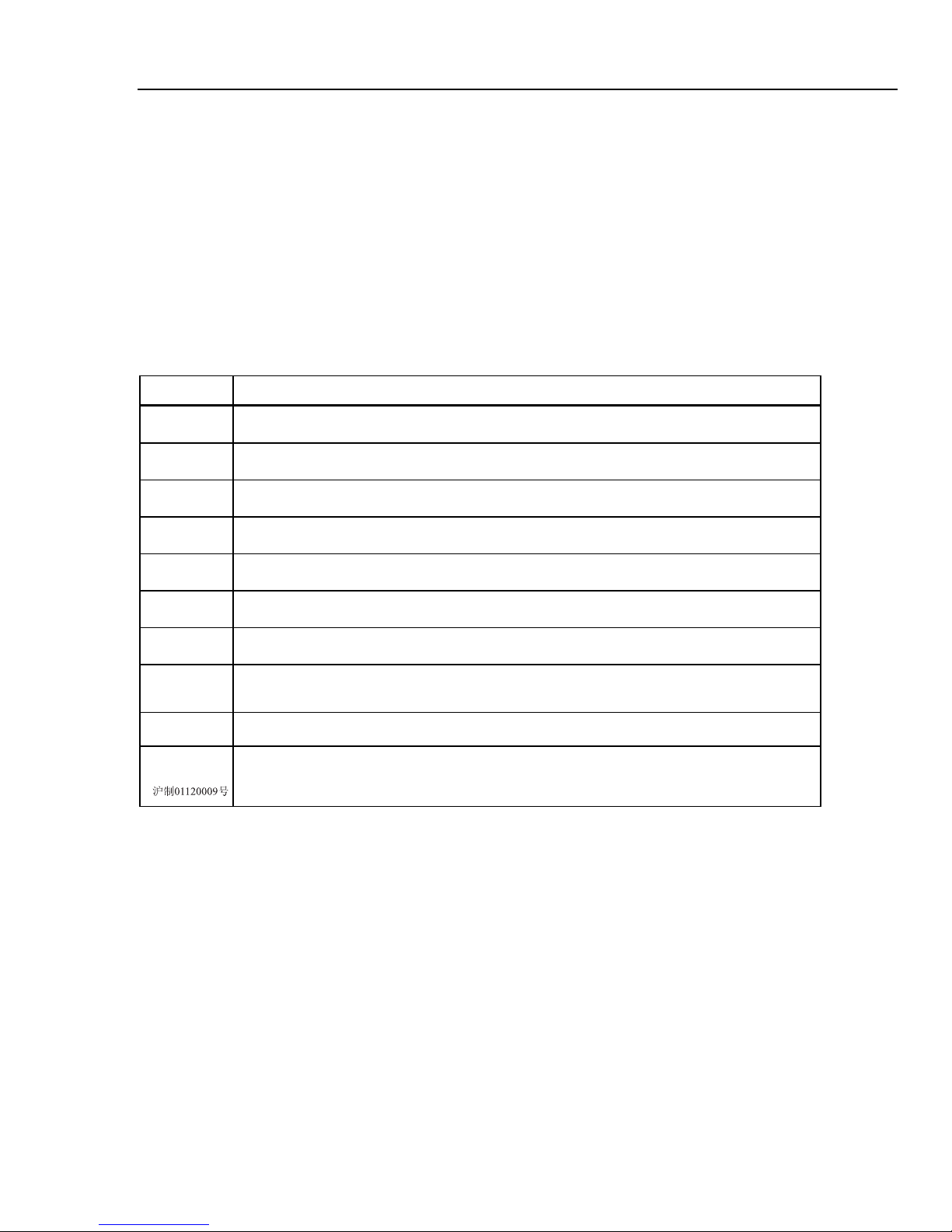
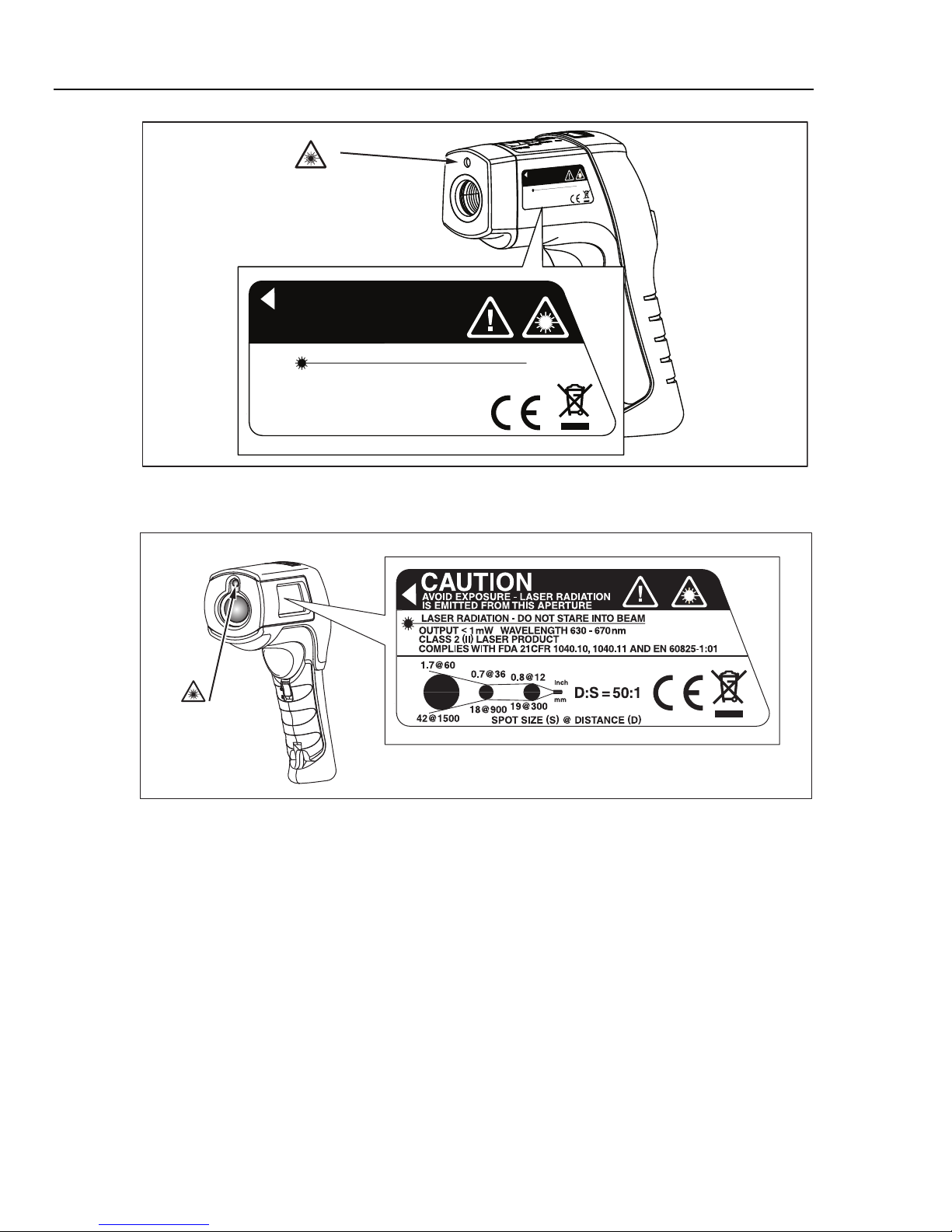
Symbols used on the Product and in this manual are explained in Table 1 and
Figures 1 and 2.
*WWarning
To prevent eye damage and personal injury:
• Read all safety Information before you use the Product.
• Do not look directly into the laser with optical tools (for
example, binoculars, telescopes, microscopes). Optical
tools can focus the laser and be dangerous to the eye.
• Do not look into the laser. Do not point laser directly at
persons or animals or indirectly off reflective surfaces.
• Do not use laser viewing glasses as laser protection
glasses. Laser viewing glasses are used only for better
visibility of the laser in bright light.
• Do not open the Product. The laser beam is dangerous
to eyes. Have the Product repaired only through an
approved technical site.
• Replace the batteries when the low battery indicator
shows to prevent incorrect measurements.
• The battery door must be closed and locked before you
operate the Product.
• Do not use the Product if it operates incorrectly.
• Do not use the Product around explosive gas, vapor, or
in damp or wet environments.
• Do not connect the optional external probe to live
electrical circuits.
• See emissivity information for actual temperatures.
Reflective objects result in lower than actual temperature
measurements. These objects pose a burn hazard.
• Do not leave the thermometer on or near objects of high
temperature.
• Use of controls or adjustments or performance of
procedures other than those specified herein may result
in hazardous laser radiation exposure.
• Use the Product only as specified, or the protection
supplied by the Product can be compromised.
2
Shop for Fluke products online at:
www.MyFlukeStore.com
1.877.766.5412
Page 11
Infrared Thermometers
WCaution
To avoid damaging the thermometer or the equipment under
test, protect them from the following:
• EMF (electro-magnetic fields) from arc welders,
induction heaters, etc.
• Static electricity
• Thermal shock (caused by large or abrupt ambient
temperature changes- for highest accuracy, allow 30
minutes for thermometer to stabilize before use).
Table 1. Symbols
Symbol Explanation
Safety Information
X
W
*
P
°C
°F
M
~
„
Hazardous voltage. Risk of electrical shock.
Risk of danger. Important information.
Warning. Laser.
Conforms to requirements of European Union and European Free Trade Association (EFTA)
Celsius
Fahrenheit
Battery
Do not dispose of this product as unsorted municipal waste. Go to Fluke’s web site for
recycling information.
Battery
China metrology certification mark for measuring instruments manufactured in the Peoples
Republic of China (PRC).
3
Shop for Fluke products online at:
www.MyFlukeStore.com
1.877.766.5412
Page 12
56x
Users Manual
Laser
Aperture
AVOID EXPOSURE - LASER RADIATION
IS EMITTED FROM THIS APERTURE
CAUTION
LASER RADIATION - DO NOT STARE INTO BEAM
OUTPUT < 1mW WAVELENGTH 630 - 670nm
CLASS 2 (II) LASER PRODUCT
COMPLIES WITH FDA 21CFR
1040.10 AND 1040.11
COMPLIES WITH IEC 60825
Figure 1. 561 Laser Safety Markings
OID EXPOSURE - LASER RADIATION
V
A
THIS APER
OM
IS EMITTED FR
CAUTION
LASER RADIATION - DO NO
VELENGTH 630 - 67
A
<
mW W
1
OUTPUT
)
(
LASER PR
II
CLASS 2
WITH FDA 21CFR
COMPLIES
1040.10 AND 1040.11
WITH IEC 60825
COMPLIES
TURE
O BEAM
T STARE INT
nm
0
ODUCT
efh010f.eps
Laser
Aperture
Figure 2. 566/568 Laser Safety Markings
eyl08b.eps
4
Shop for Fluke products online at:
www.MyFlukeStore.com
1.877.766.5412
Page 13

Infrared Thermometers
Features
Features
561:
• Single-spot laser sighting
• Backlit display
• Current Temperature plus MAX, MIN, DIF, AVG temperature displays
• Two AA batteries
• Hard case
• 80PK-1 and 80PK-11 K-type thermocouple probe
• Adjustable emissivity and predefined emissivity table
• Infrared and thermocouple temperature display
• Celsius or Fahrenheit temperature display
• Tripod mount
• Auto off
• Standard miniature K-type thermocouple connector input
• Printed 56x Getting Started Guide
• 56x Manuals CD
566 and 568 include items listed above plus:
• 12 or 24 hour clock
• Last reading Hold (20 seconds)
• Multi-language interface
• High and low alarm
• Data storage and review
• Trigger lock
• USB 2.0 computer interface cable (568)
• FlukeView Forms Documenting Software (568)
5
Shop for Fluke products online at:
www.MyFlukeStore.com
1.877.766.5412
Page 14
56x
Users Manual
561 Display
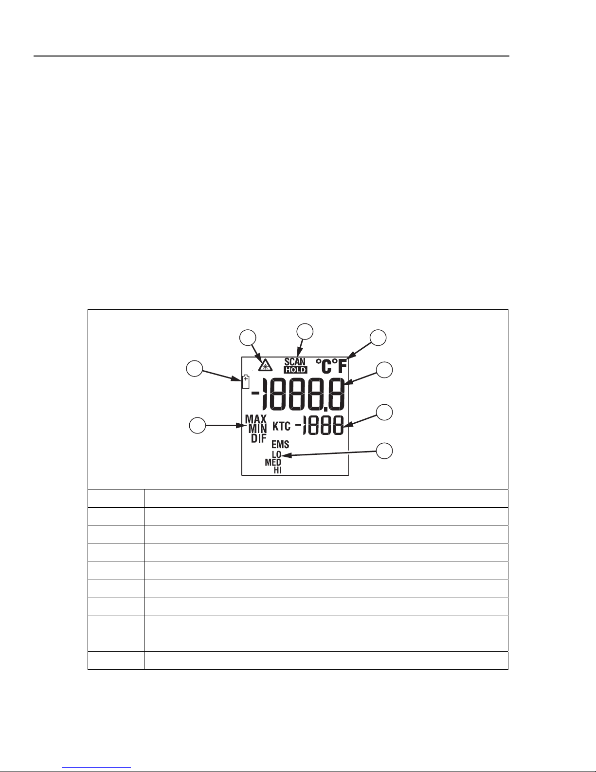
The primary temperature display reports the current or last IR temperature read
until the 7-second hold time elapses.
The secondary temperature display reports current thermocouple temperature
when a type-K thermocouple is attached. When a thermocouple is not
connected, the small temperature display reports a choice of maximum,
minimum, or difference between maximum and minimum temperature.
You can toggle through the minimum, maximum, and difference IR temperatures
anytime the display is on. The MIN, MAX, and DIF temperatures are constantly
calculated and updated when the trigger is pressed. After the trigger is released,
the MIN, MAX, DIF temperatures are held for 7 seconds.
Note
When the battery is low, appears on the display.
The last selection (MIN/MAX/DIF) is maintained on the secondary display even
after the Thermometer has been turned off, providing the batteries have not
failed. See Figure 3.
1
8
2
3
4
5
7
6
efh01af.eps
Number Description
Laser “On” symbol
SCAN or HOLD
°C/°F symbol (Celsius/Fahrenheit)
Primary temperature display
Secondary temperature display
Emissivity LO, MED, HI
Low Battery symbol. Appears when the battery charge is <25 %.
6
Shop for Fluke products online at:
Temperature values for the MIN, MAX, DIF, KTC.
KTC indicates the thermocouple temperature.
Figure 3. 561 Thermometer Display
www.MyFlukeStore.com
1.877.766.5412
Page 15
Infrared Thermometers
566/568 Display
566/568 Display
The 566/568 thermometers display can show data in the following languages:
• English
• Spanish
• French
• German
• Portuguese
• Japanese
• Simplified Chinese
To change the displayed language, refer to “Setup”.
566/568 Menu Overview
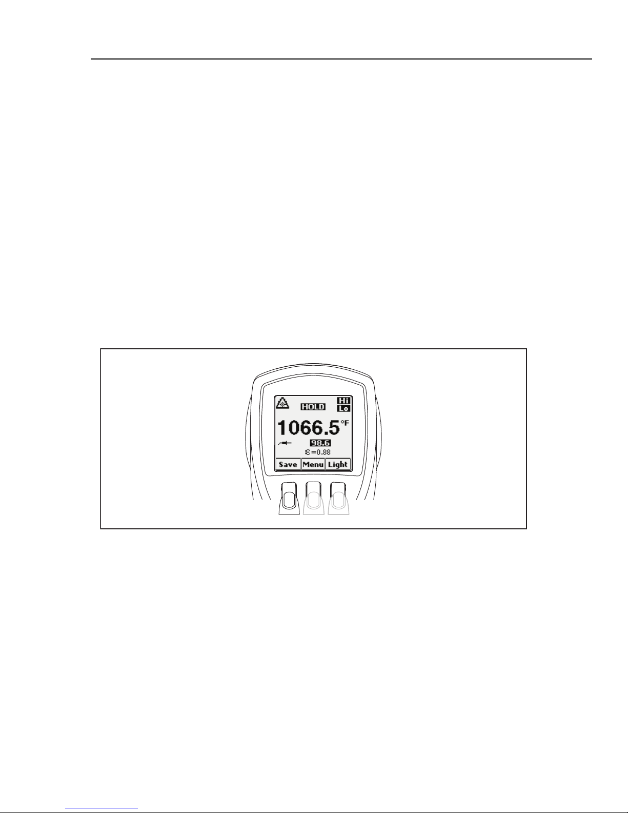
There are many settings that can be easily changed by using the menu. Figure 4
shows the LCD and menu interface. Selecting the Menu softkey advances the
menu to the next level. Table 2 is a top-level description of the menu.
7
Shop for Fluke products online at:
Figure 4. Menu Navigation
www.MyFlukeStore.com
eyl01a.eps
1.877.766.5412
Page 16

56x
Users Manual
Table 2. Top-Level Menu Description
Level
1 Save Save reading to memory Menu Light
2 Mem Review/delete memories Menu Set emissivity
3 MnMx Enables Min/Max Menu Avg Enable Avg/Diff
4 °C/°F Toggle between C and F Menu Alarm Set and enable alarms
5
6 Setup
Left
Softkey
Lock the thermometer on Menu Laser Toggle the laser on/off
(Lock)
- Turn off/on backlight
- Change Time/Date
- Change Language
Description
Center
Softkey
Menu - -
Right
Softkey
Description
Adjust backlight
brightness
Each menu item and function is explained in greater detail in the following
sections.
Save
To save readings:
1. Pull the trigger to take a measurement.
Light
2. Release the trigger to stop taking the measurement.
3. Press the Save softkey to enter the Save menu.
4. Press the Yes softkey to save the reading.
The reading is assigned a memory location and a time and date stamp.
The reading includes:
• IR temperature
• Thermocouple temperature (if connected)
• Emissivity
• Min/Max/Avg/Dif (if either Min/Max or Avg/Dif is enabled)
• Date/Time
You may also press the Cancel softkey to abort saving the reading.
The thermometers are equipped with a backlit display with two brightness levels.
The Light softkey is used to adjust the backlight brightness. The backlight is on
each time the trigger is pulled.
To toggle the backlight brightness, press the Light softkey.
The backlight can be disabled using the Setup menu. See “Setup” for more
information.
8
Shop for Fluke products online at:
www.MyFlukeStore.com
1.877.766.5412
Page 17

Infrared Thermometers
Memory
The thermometers can store measurement records including time, date,
emissivity, and measurement record numbers (see “Save” for more information).
The 566 can store 20 records and the 568 can store 99.
To access records stored in memory:
1. Press the Menu softkey until Mem appears as the left softkey function.
2. Press the Mem softkey to access the Memory menu. Saved readings can be
read.
Emissivity Menu
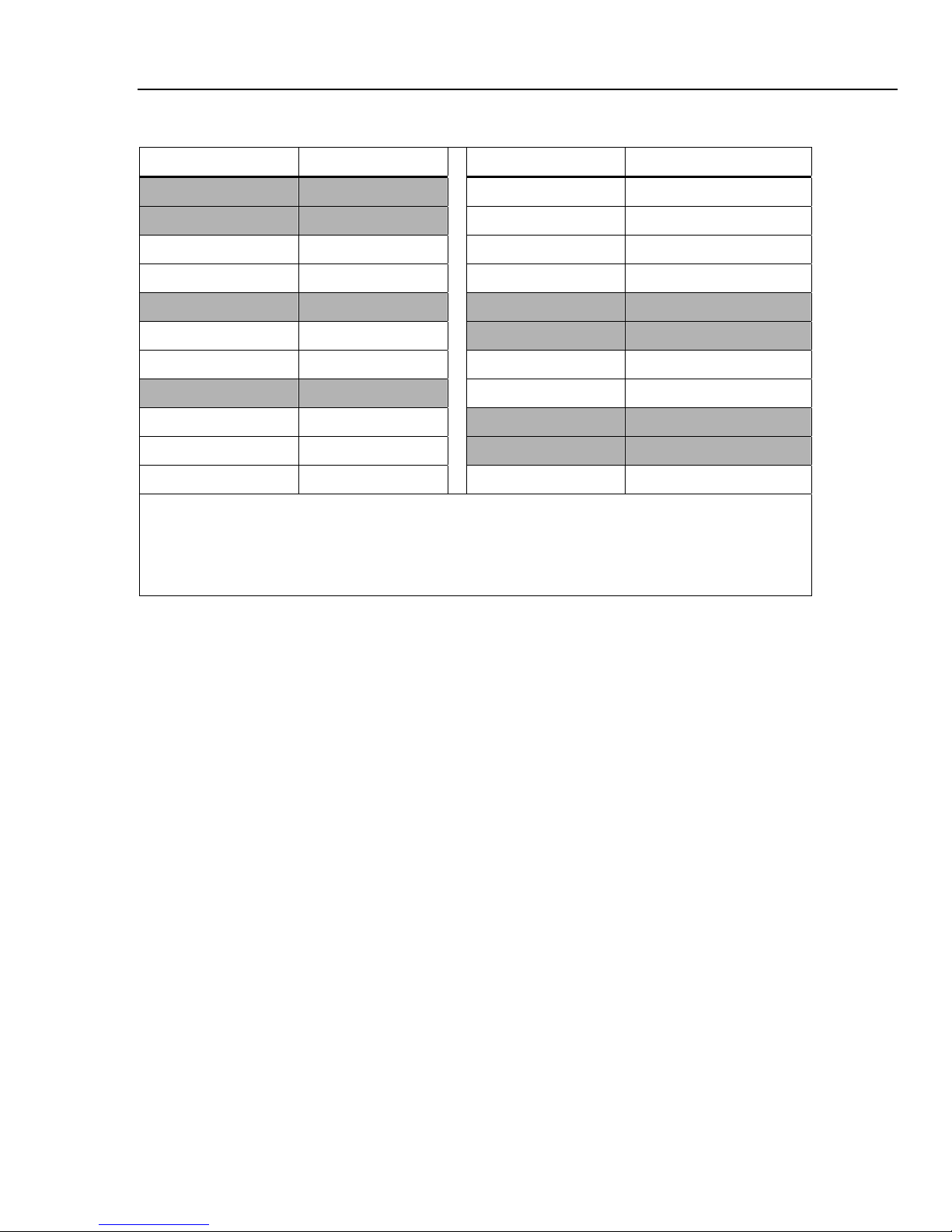
The Emissivity menu includes a list of pre-defined materials and lists their typical
emissivity values, see Tables 3 and 4. For further information, see “Emissivity”.
Note
Default emissivity is 0.95.
To access the Emissivity menu:
1. Press the Menu softkey until (emissivity) appears as the right softkey
function.
566/568 Display
2. Press the softkey.
The Emissivity list may be accessed by pressing the Table softkey or a material’s
typical emissivity may be entered manually by pressing the No. softkey.
• If the Emissivity table is accessed, a listing of materials and their suggested
emissivity is shown.
1. Use the down arrow to navigate through the list.
2. Press the Enter softkey to choose the desired material.
• To enter an emissivity value manually:
1. Press the No. softkey.
2. Use the down or up arrow softkey to change the entry. Hold down the up
or down arrow softkey to increase the rate of change.
3. Press the Done softkey when finished to return to the main menu.
9
Shop for Fluke products online at:
www.MyFlukeStore.com
1.877.766.5412
Page 18

56x
Users Manual
Table 3. Surface Emissivity (561)
Materials
Aluminum Iron, Cast
Oxidized Low Oxidized High, Medium
Alloy A3003 Unoxidized Low
Oxidized Low Molten Low
Roughened Low Iron, Wrought
Brass Dull High
Burnished Low Lead
Oxidized Low Rough Low
Copper Oxidized Low, Medium
Oxidized Medium Molybdenum
Electrical Terminal
Blocks
Haynes Nickel
Alloy Medium Oxidized Low
Inconel Platinum
Switch Setting Materials Switch Setting
Medium Oxidized Low, Medium
Oxidized High, Medium Black High
Sandblasted Medium Steel
Electoropolished Low Cold-Rolled High
Iron Ground Sheet Medium
Oxidized High, Medium Polished Sheet Low
Rusted Medium Zinc
Oxidized Low
10
Shop for Fluke products online at:
www.MyFlukeStore.com
1.877.766.5412
Page 19
Infrared Thermometers
Table 4. Nominal Surface Emissivity (566/568)
Material Value Material Value
Default**** 0.95 Glass (plate) 0.85
Aluminum* 0.30 Iron* 0.70
Asbestos 0.95 Lead* 0.50
Asphalt 0.95 Oil 0.94
Brass* 0.50 Paint 0.93
Ceramic 0.95 Plastic** 0.95
Concrete 0.95 Rubber 0.95
Copper* 0.60 Sand 0.90
Food - Frozen 0.90 Steel* 0.80
Food - Hot 0.93 Water 0.93
Wood *** 0.94
* Oxidized
** Opaque, over 20 mils
*** Natural
**** Factory Setting
Highlighted items may also be found in the emissivity table built into the thermometer.
566/568 Display
°
C and °F
To toggle between °C (Celsius) and °F (Fahrenheit) measurements, press the
Menu softkey until °C or °F appears as the left softkey function. Press the
corresponding softkey to change between the measurements.
Min, Max, Avg, Differential
The thermometers can measure minimum (MIN), maximum (MAX), average
(AVG), or differential (Δ) temperatures each time a reading is taken. These
values are not shown if a thermocouple is plugged into the thermometer.
To turn on the Min Max mode:
1. Press the Menu softkey until MnMx (Min Max) appears as the left softkey
function.
2. Press the MnMx softkey.
The display shows the present reading, maximum and minimum readings, and
the emissivity setting.
To turn on the Avg/Dif mode:
1. Press the Menu softkey until Avg appears as the right softkey function.
2. Press the Avg softkey.
The display shows the present reading, average reading, the differential reading
between max and min (designated by Δ), and the emissivity setting.
11
Shop for Fluke products online at:
www.MyFlukeStore.com
1.877.766.5412
Page 20

56x
Users Manual
Note
Min, Max, Avg, and Differential readings are saved as part of the
saved data when either Min/Max or Avg/Dif mode is enabled.
Alarm
The thermometers have a programmable high and low alarm to designate high or
low readings depending on the thresholds entered. When the alarm level is
reached, an alarm will sound and the display will flash orange and white. To set
either the high or low alarm:
1. Press the Menu softkey until Alarm appears as the right softkey function.
2. Press the Alarm softkey to access the Alarm menu.
3. Press either the Hi or Lo softkey, depending on which alarm will be set.
4. Press the ON softkey to turn the alarm on.
5. Press the OFF softkey to turn the alarm off.
6. Use the Set softkey to access the Hi or Lo Alarm Set menu.
7. Use the down or up softkeys to change the alarm setting.
8. Once the desired settings have been entered, press the Done softkey.
Trigger Lock
The thermometer trigger can be locked on for continuous measurement. To lock
the trigger:
1. Press the Menu softkey until the lock symbol () appears as the left softkey
function.
2. Press the softkey to lock the trigger. The lock symbol appears on the
display to designate a locked trigger. When the trigger is locked, the
softkey changes to . Press this softkey to unlock the trigger.
Laser
To prevent eye damage and personal injury:
The thermometer is equipped with a laser used for aiming purposes only. The
laser turns off when the trigger is released.
To enable or disable the laser:
1. Press the Menu softkey until Laser appears as the right softkey function.
*WWarning
• Do not look into the laser. Do not point laser directly at
persons or animals or indirectly off reflective surfaces.
2. Press the Laser softkey to enable or disable the laser. * appears on the
display when the laser is enabled.
12
Shop for Fluke products online at:
www.MyFlukeStore.com
1.877.766.5412
Page 21

Infrared Thermometers
Setup
From the Setup menu, the backlight, time and date, and display language can be
changed.
Backlight
In normal use, the backlight is always on. Use this menu to change the backlight
setting from on to off. Turning the backlight off conserves battery power.
1. Press the Menu softkey until Setup appears as the left softkey function.
2. Press the Setup softkey.
3. Backlight has an indicator next to it. To enter the backlight menu, press the
Enter softkey.
4. Press the OFF softkey to turn the backlight off, press the ON softkey to turn it
on.
5. Press the Back softkey to return to the Setup Menu.
Time/Date
To change the time on the thermometer:
566/568 Display
1. Press the Menu softkey until Setup appears as the left softkey function.
2. Press the Setup softkey to enter the Setup menu.
3. Press the down arrow softkey to select Time/Date.
4. Press the Enter softkey.
5. Select the Time softkey.
6. Select the desired time format softkey (24hr or 12hr).
7. Use the up and down softkeys to change the selected hour to the desired
hour.
8. Press the Next softkey to select the minutes.
9. Use the up and down softkeys to change the selection to the desired minute.
10. When in 12 hour mode, press the Next softkey to highlight the am/pm
parameter.
11. Use the up and down softkey to change to am or pm.
12. Press the Done softkey when finished. The display reverts to the first page of
the Time/Date menu.
13
Shop for Fluke products online at:
www.MyFlukeStore.com
1.877.766.5412
Page 22

56x
Users Manual
To change the date on the thermometer:
1. From the main menu, press the Menu softkey until Setup appears as the left
softkey function.
2. Press the Setup softkey.
3. Press the down arrow softkey to select Time/Date.
4. Press the Enter softkey.
5. Press the Date softkey.
6. Select the date format: Day/Month/Year (dmy) or Month/Day/Year (mdy).
7. Use the up and down softkeys to change the selected parameter.
8. Press the Next softkey and the arrow softkeys to select the month, date, or
year parameters.
9. Use the up and down softkeys to change the selected parameter.
10. Press the Next softkey to move through each parameter.
11. Press the Done softkey when finished. The display reverts to the beginning of
the Time/Date menu.
Language
To change the displayed language:
1. From the main menu, press the Menu softkey until Setup appears as the left
softkey function.
2. Press the Setup softkey.
3. Use the down arrow softkey to move the indicator to Language.
4. Press the Enter softkey.
5. Use the down arrow to move the indicator to the desired language.
6. Press the Enter softkey to complete the language selection or press the
Back softkey to return to the Setup menu.
Deleting Data
To delete stored data from the thermometer, from the main menu, press the
menu softkey until Mem shows as the left softkey function. The last memory
location appears on the display. To access the Delete menu, press the Delete
softkey. From here, either all of the thermometer memory can be deleted or
individual records.
Deleting All Data
To delete all of the records, press the All softkey. At the confirmation screen,
press the Yes softkey.
14
Shop for Fluke products online at:
www.MyFlukeStore.com
1.877.766.5412
Page 23
Infrared Thermometers
Buttons and Connector
Deleting Individual Data Records
To delete individual records, press the View softkey and then use the down and
up arrow softkeys to access the desired record. Once the desired record is
shown, press the Yes softkey to delete the record. To cancel data deletion, pull
the trigger.
Buttons and Connector
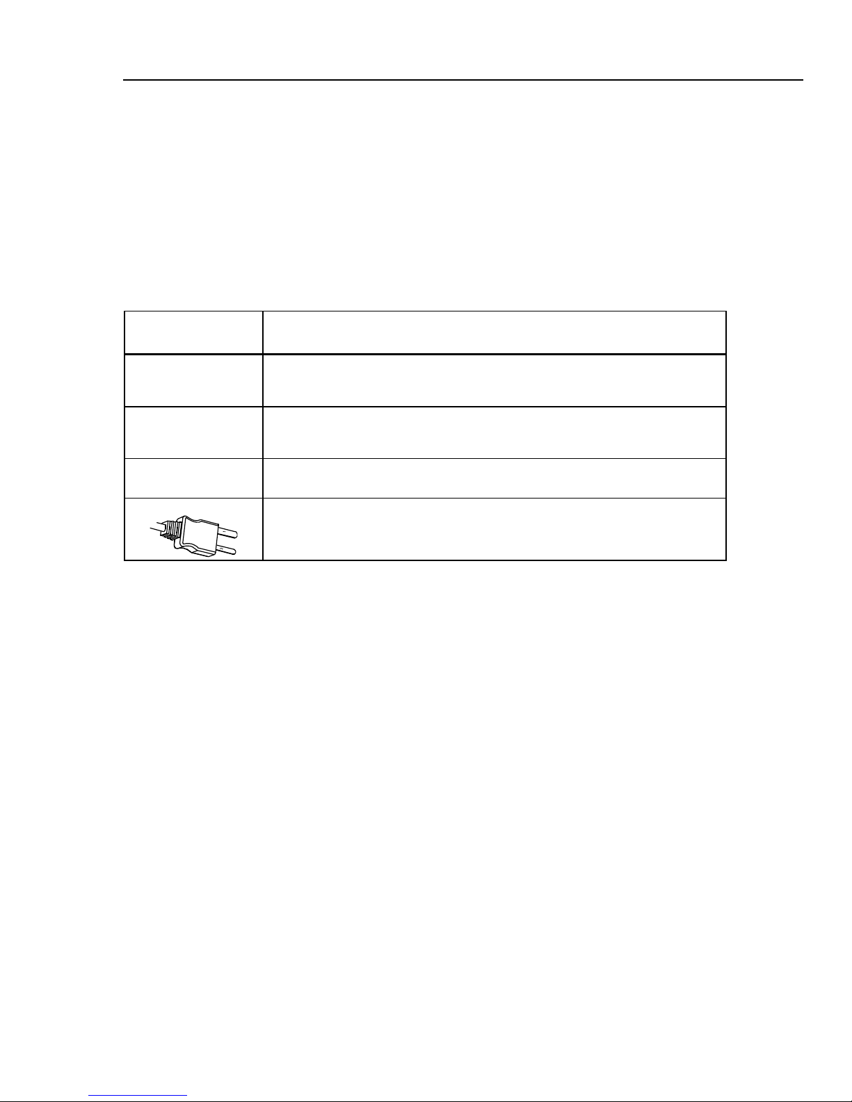
Table 5 shows the buttons and connector used for the thermometers.
Table 5. Buttons and Connector
Button/
Connector
(561)
(561)
Description
and then press
Press
Selects the emissivity setting. You can toggle between LO (0.3), MED (0.7), or HI
(0.95) using
The button is used to show the MIN, MAX, and DIF functions in the secondary
display, whichever was pressed most recently.
K-type thermocouple probe used to make contact temperature measurement.
.
to toggle between the MIN, MAX, and DIF options.
15
Shop for Fluke products online at:
www.MyFlukeStore.com
1.877.766.5412
Page 24
56x
Users Manual
How the Thermometers Work
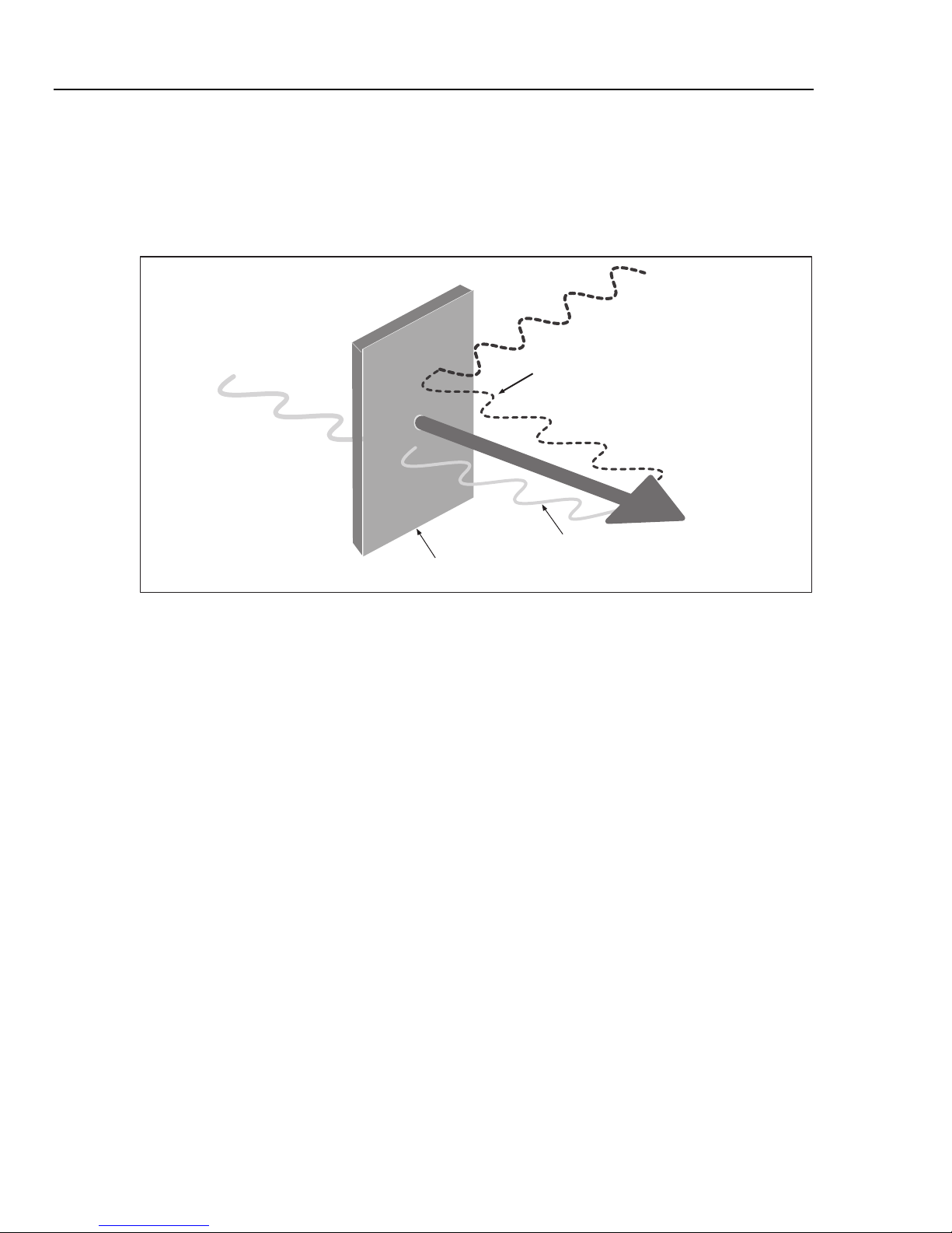
Infrared thermometers measure the surface temperature of an object. The
thermometer’s optics sense emitted, reflected, and transmitted energy, which is
collected and focused onto a detector. The unit’s electronics translate the signal
into a temperature reading which the unit displays (see Figure 5).
Reflected energy
Target
Figure 5. How the Thermometer Works
Operating the Thermometer
Temperature Measurement
To measure temperature, point the thermometer at an object and pull the trigger.
You can use the laser pointer to help aim the thermometer. You may also insert
the K-type thermocouple probe for contact measurement. Be sure to consider
distance-to-spot size ratio and field of view (see “Distance and Spot Size” and
“Field of View”). The temperature appears on the display.
The laser is used for aiming purposes only and is not related to
temperature measurement.
The thermometer features an auto off function that automatically powers down
the thermometer after 20 seconds of inactivity. To turn the thermometer on, pull
the trigger.
Note
Transmitted
energy
Emitted
Energy
eyl002f.eps
16
Shop for Fluke products online at:
www.MyFlukeStore.com
1.877.766.5412
Page 25
Infrared Thermometers
Operating the Thermometer
Locating a Hot or Cold Spot
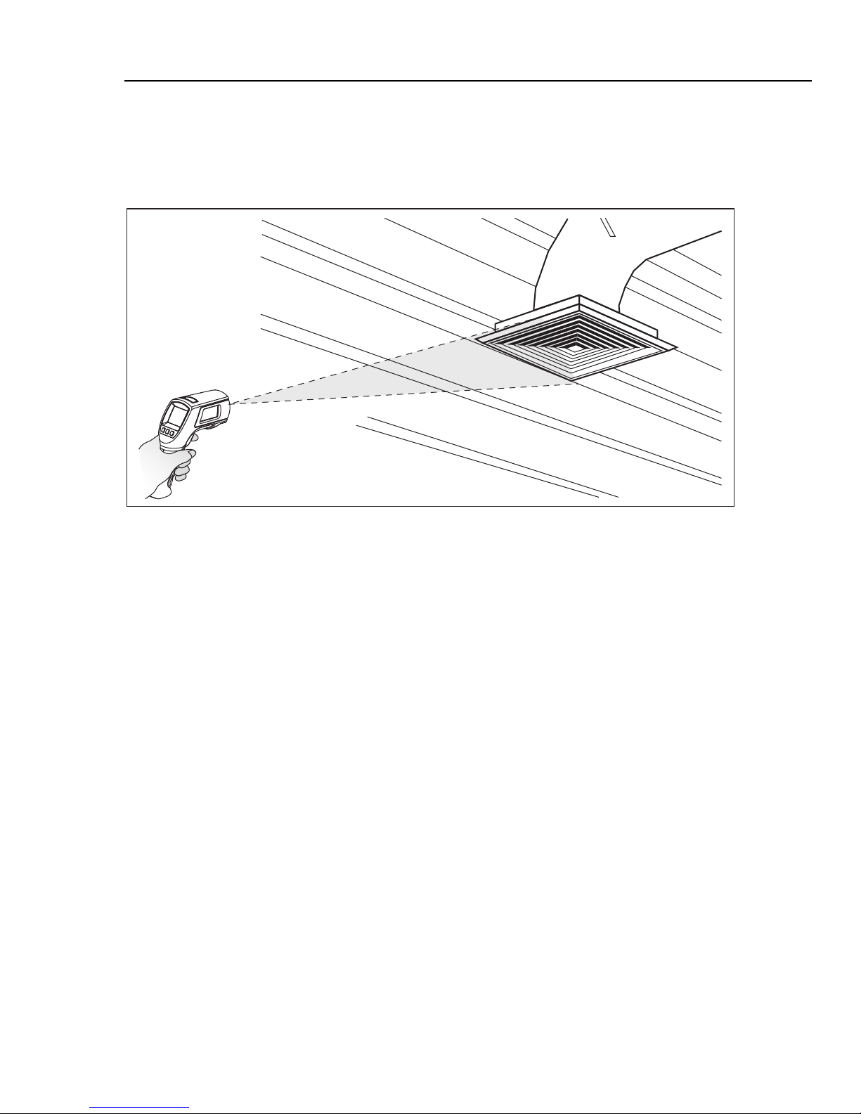
To find a hot or cold spot, aim the thermometer outside the desired area. Then,
slowly scan across the area with an up and down motion until you locate the hot
or cold spot (see Figure 6).
Figure 6. Locating a Hot or Cold Spot
eyl07.eps
17
Shop for Fluke products online at:
www.MyFlukeStore.com
1.877.766.5412
Page 26
56x
Users Manual
Distance and Spot Size
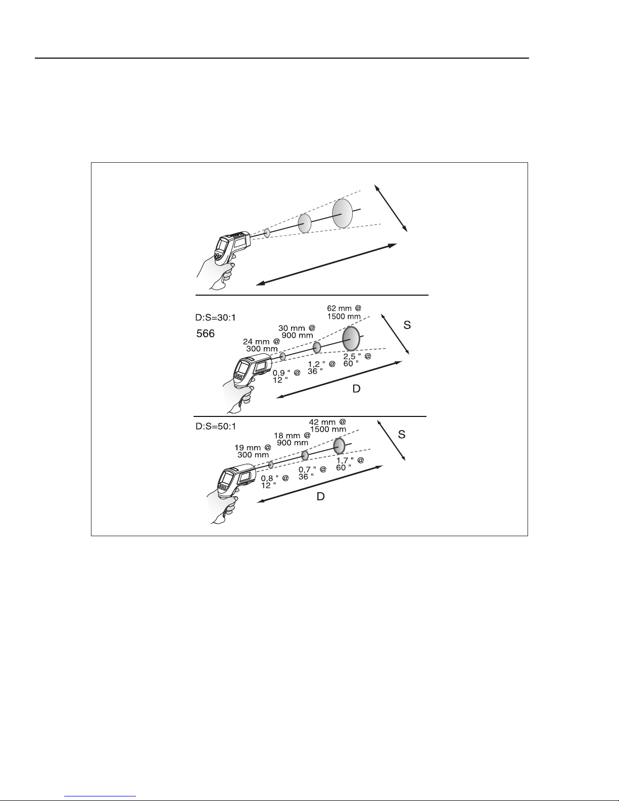
As the distance (D) from the object being measured increases, the spot size (S)
of the area measured by the unit becomes larger. The relationship between
distance and spot size (D:S) for each unit is shown in Figure 7. The spot sizes
indicate 90 % encircled energy.
D:S=12:1
561
38 mm @
300 mm
75 mm @
900 mm
1.5 " @
12 "
132 mm @
1500 mm
3 " @
36 "
5.3 " @
60 "
S
D
568
Figure 7. Distance and Spot Size
eyl06a.eps
18
Shop for Fluke products online at:
www.MyFlukeStore.com
1.877.766.5412
Page 27
Infrared Thermometers
Operating the Thermometer
Field of View
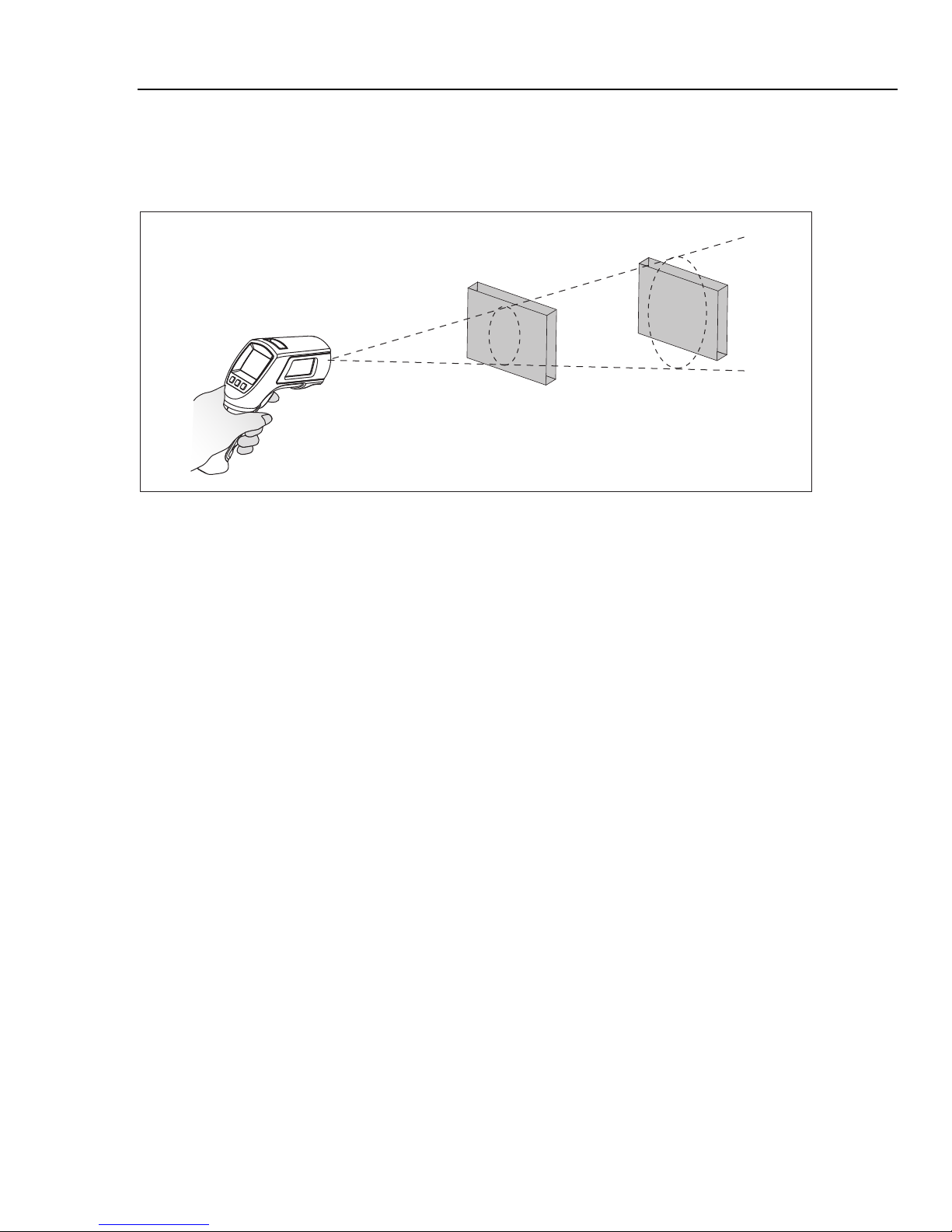
For accurate measurements, make sure that the target is larger than the unit’s
spot size. The smaller the target, the closer you should be to it (see Figure 8).
Ye s No
Figure 8. Field of View
eyl05.eps
Emissivity
Emissivity describes the energy-emitting characteristics of materials. Most
organic materials and painted or oxidized surfaces have an emissivity of
approximately 0.95, the default setting for the thermometer.
To compensate for inaccurate readings that may result from measuring shiny
metal surfaces, you can cover the surface to be measured with electrical tape or
flat black paint (<148 °C/300 °F) with emissivity set to 0.95. Allow time for the
tape or paint to reach the same temperature as the surface beneath it. Measure
the temperature of the tape or painted surface.
If you cannot paint or use tape, then you can improve the accuracy of your
measurements by either numerically adjusting emissivity or by using the
Emissivity Menu to access a table of some common materials. The
thermometers have numerically adjustable emissivity from 0.10 to 1.00 that can
be used in conjunction with the emissivities in Tables 3 and 4. Also, the
thermometers have a built-in table of the most common materials that can be set
from the Emissivity Menu. The built-in values are indicated in Tables 3 and 4.
HOLD
The display retains its last infrared measurement for twenty seconds when the
trigger is released, with HOLD appearing on the display. With the probe inserted,
the contact thermometer remains on. To freeze the infrared temperature when a
probe is not inserted, release the trigger until HOLD appears on the display.
19
Shop for Fluke products online at:
www.MyFlukeStore.com
1.877.766.5412
Page 28
56x
Users Manual
Storing Data
The 566 thermometer can store up to 20 data records. The 568 thermometer can
store up to 99 data records. The following information is stored in each record:
• Record number
• IR and probe temperature in °F or °C
• Date/Time
• Emissivity
• Max/Min/Avg/Dif Temperature (if enabled)
For more information, see “Save”.
Downloading Data
The stored data of the 568 can be downloaded to a personal computer (PC) via
the included USB cable and the included FlukeView Forms Documenting
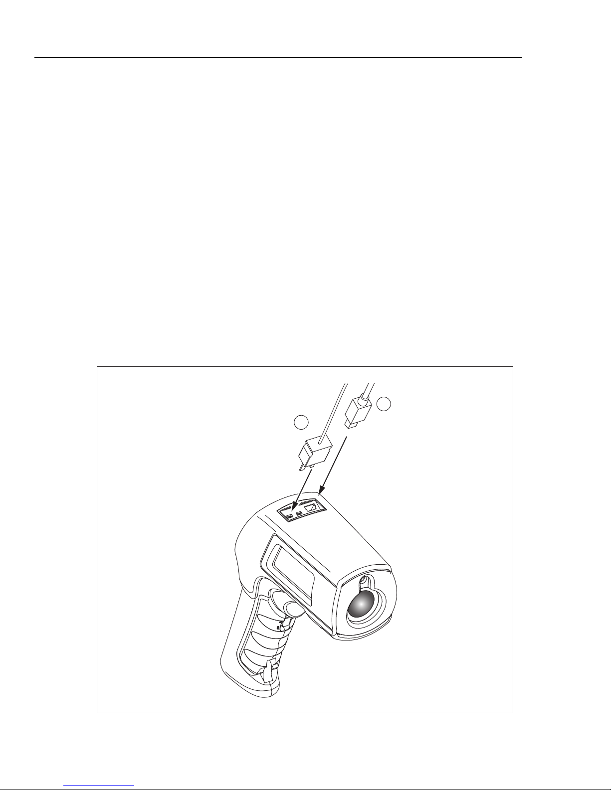
Software. See the FlukeView Forms documentation for details. The USB input
is located on the top of the thermometer next to the external probe input
(see Figure 9).
Note
To prevent incorrect readings, do not perform a temperature
measurement of an earthed conductor while the 568 is connected to
a PC that is earthed by a three-phase grounding plug.
2
1
20
Shop for Fluke products online at:
Figure 9. Thermocouple and USB Connections
www.MyFlukeStore.com
eyl03.eps
1.877.766.5412
Page 29

Infrared Thermometers
External Contact Probe
External Contact Probe
XWWarning
To avoid electrical shock or personal injury, do not connect the
external contact probe to live electrical circuits.
The thermometers come with a bead K-type thermocouple probe. The probes
attach to the thermometers via the probe input located on the top of the
thermometer (see Figure 9).
With the probe installed, the probe symbol () appears on the display. The
probe can be used simultaneously while the thermometer is taking non-contact
measurements. The probe readings are shown below the non-contact
measurements. The thermometer will stay on when there is a probe inserted.
When used with a personal computer and FlukeView Forms (568 only), the auto
off feature is disabled.
Troubleshooting
See Table 6 for remedies to possible problems when using the thermometer.
Table 6. Troubleshooting
Symptom Cause Action
--- (on display)
Low batteries Replace Batteries
Blank display
Laser does not work
Failed communication via USB
Inaccuracy
Settings such as emissivity,
date/time, F/C, and saved data
lost
Target temperature is over or
under range.
Thermometer is asleep
Possible dead batteries
Low or dead batteries
Ambient temperature is above
40 °C (104 °F)
Unit is off
FlukeView Forms is not running
Possible incorrect emissivity
setting, field of view, or spot size
Battery dead or not replaced in
<1 minute of removal
Select target within
specifications
Pull trigger
Replace batteries
Replace batteries
Use in area with lower ambient
temperature
Pull the trigger
Start FlukeView Forms
See “Emissivity”, “Field of View”
and “Distance and Spot Size”
sections.
Reset settings. Replace
batteries as soon as low battery
indicated; Exchange the
batteries within one minute of
removal. Refer to “Changing the
Batteries”.
21
Shop for Fluke products online at:
www.MyFlukeStore.com
1.877.766.5412
Page 30

56x
Users Manual
Maintenance
Battery Charge
Use the battery charge symbols to gauge the approximate level of charge left on
the batteries.
Notes
When in low battery mode, the thermometer does not store values.
“Err” appears on the display if attempted.
Changing the Batteries
Batteries contain hazardous chemicals that can cause burns or
explode. If exposure to chemicals occurs, clean with water and
get medical aid. To prevent injury and for safe operation and
maintenance:
• Remove all probes, test leads, and accessories before the
battery door is opened.
• Do not disassemble the battery.
• Repair the Product before use if the battery leaks.
• Remove batteries to prevent battery leakage and damage
to the Product if it is not used for an extended period.
• Be sure that the battery polarity is correct to prevent
battery leakage.
• Do not short the battery terminals together.
• Do not disassemble or crush battery cells and battery
packs.
Batteries are at 5 %. Before taking further readings, the batteries
must be changed.
WWarning
• Do not keep cells or batteries in a container where the
terminals can be shorted.
• Do not put battery cells and battery packs near heat or fire.
Do not put in sunlight.
The batteries should be replaced in less than one minute after
removal to avoid manually re-initializing the thermometer clock and
date.
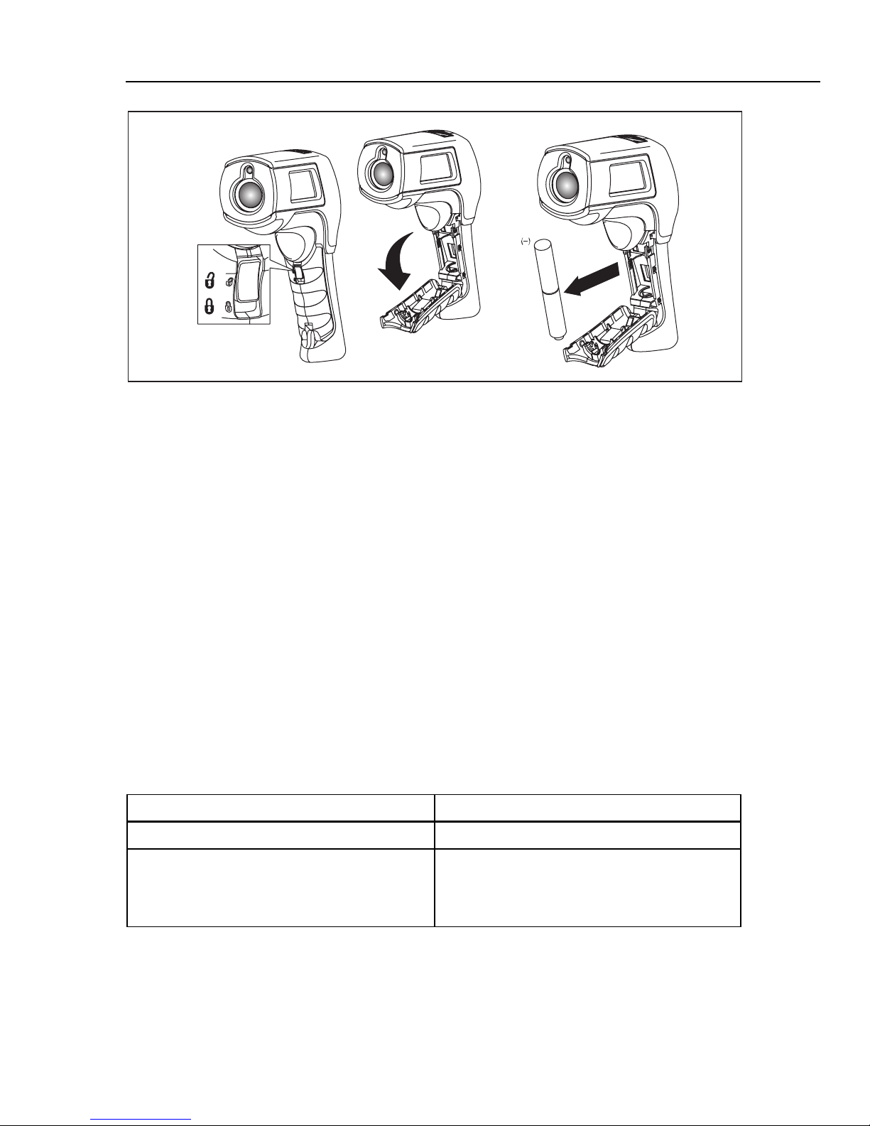
To install or change the two AA batteries (see Figure 10):
1. Slide the locking tab on the battery door to the “unlock” position and then
open the handle.
2. Insert the batteries noting their correct polarity.
3. Close and lock the handle.
22
Shop for Fluke products online at:
Note
www.MyFlukeStore.com
1.877.766.5412
Page 31
Infrared Thermometers
Figure 10. Battery Replacement
User Replaceable Parts and Accessories
AA
(+)
eyl04.eps
Cleaning the Lens
Blow off loose particles using clean compressed air. Carefully wipe the surface
with a water-moistened cotton swab.
Cleaning the Housing
Use soap and water on a damp sponge or soft cloth.
WCaution
To avoid damaging the thermometers, do NOT submerge them
in water. Do not use abrasive cleaners, they will damage the
case.
User Replaceable Parts and Accessories
User Replaceable Parts
See Table 7 for a list of replaceable parts.
Table 7. Replaceable Parts
Part Part Number
56x Manuals CD 3833037
56x Getting Started
(English, French, German, Spanish, Portuguese,
Japanese, Simplified Chinese, Italian, Russian,
Polish, Czech)
3833028
23
Shop for Fluke products online at:
www.MyFlukeStore.com
1.877.766.5412
Page 32

56x
Users Manual
Accessories
Optional accessories for the thermometers are:
• Soft Carrying Case (H6)
• Calibration Certification
• All Type-K Temperature Probes with standard mini-connector. See Table 8
for more information.
Recommended Temperature Probes
See Table 8 for a list of recommended temperature probes.
Table 8. Recommended Temperature Probes
Probe Usage
80PK-1
80PK-8
80PK-9
80PK-11
80PK-25
80PK-26
The general purpose bead probe is an alternative, for quick, accurate surface
temperatures and air temperatures within ducts, vent temperatures.
Pipe clamp probes (2) are essential for tracking continuously changing
temperature differentials on hydronic tubing and pipe loops, and good for quick,
accurate refrigerant temperatures.
The insulation piercing probe provides a sharp tip to pierce pipe insulation and flat
probe tip for good surface thermal contact, air temperatures within ducts, and vent
temperatures.
Flexible Cuff Thermocouple Temperature Probe is a convenient way to attach a
thermocouple to a pipe while keeping hands free.
The piercing probe is the most versatile option. Good for checking air temperature
in ducts, surface temperature under carpets/pads, liquids, thermometer wells, vent
temperatures, and for penetrating pipe insulation.
The tapered probe is a good general-purpose gas and surface probe, with a good
length and low mass tip casing for faster reaction to surface and air temperatures.
24
Shop for Fluke products online at:
www.MyFlukeStore.com
1.877.766.5412
Page 33

Infrared Thermometers
Specifications
Specifications
Feature 561 566 568
IR Temperature Range
Accuracy
Repeatability
Display Resolution 0.1 °C / 0.1 °F
Spectral Response 8 to 14 μm
Response Time (95 %) <500 ms
K-Type Thermocouple
Input Temperature Range
K-Type Thermocouple
Input Accuracy
K-Type Thermocouple
Resolution
Distance:Spot
(90 % energy)
Laser sighting Single laser, output <1 mW Class II, wavelength 630 to 670 nm
Emissivity Lo, Med, Hi
Data storage - 20 points 99 points
Communication none USB 2.0
Operating Altitude 3000 meters above mean sea level
Storage Altitude 12,000 meters above mean sea level
Relative Humidity 10 % to 90 % RH non-condensing up to 30 °C (86 °F)
Operating Temperature
Storage Temperature
Vibration 2.5 G, IEC 68-2-6
Weight 0.322 kg (0.7099 lb)
Dimensions 17.69 cm (6.965 in) H x 16.36 cm (6.441 in) L x 5.18 cm (2.039 in) W
Power
Battery Life
CE Certification
-40 °C to 550 °C
(-40 °F to 1022 °F)
<0 °C: ±(1.0 °C + 0.1 °/1 °C)
>0 °C: ±1 % or ± 1.0 °C, whichever is greater
(<32 F±2 °F ±0.1 °/1 °F)
>32 °F: ±1 % or ±2 °F), whichever is greater
±0.5 % of reading or
±1 °C (2 °F),
whichever is greater.
0 °C to 100 °C
(32 °F to 212 °F)
Input accuracy ±2.2 °C
(±4 °F)
0.1 °C (0.1 °F) 0.1 °C/0.1 °F
12:1 30:1 50:1
0 °C to 50 °C
(32 °F to 122 °F)
-20 °C to 65 °C
(-4 °F to 149 °F)
2 AA /LR6 Batteries (alkaline or NiCD)
12 hours with laser and backlight on; 100 hours with laser and backlight
off, at 100 % duty cycle (thermometer continuously on)
EN/IEC 61326-1:2006, Class B, Criteria A
EN/IEC 61010-1:2001
EN/IEC 60825-1:2007
-40 °C to 650 °C
(-40 °F to 1202 °F)
±0.5 % of reading or ±0.5 °C (1 °F),
whichever is greater.
-270 °C to 1372 °C (-454 °F to 2501 °F)
-270 °C to -40 °C: ±(1 °C + 0.2 °/1 °C)
(-454 °F to -40 °F: ±(2 °F + 0.2 °/1 °F))
-40 °C to 1372 °C: ±1 % or 1 °C (-40 °F to
2501 °F: ±1 % or 2 °F), whichever is greater
Digitally adjustable from 0.10 to 1.00 by 0.01
or via built-in table of common materials
0 °C to 50 °C (32 °F to 122 °F)
-20 °C to 60 °C (-4 °F to 149 °F)
-40 °C to 800 °C
(-40 °F to 1472 °F)
2 AA /LR6 Batteries
or USB connection
when used with a
PC
25
Shop for Fluke products online at:
www.MyFlukeStore.com
1.877.766.5412
Page 34
56x
Users Manual
561 Accessory
Feature K-Type Thermocouple Probe (Wrap Type)
Measurement Range 0 °C to 100 °C (32 °F to 212 °F)
Accuracy ±2.2 °C (4.0 °F)
Cable Length
505 mm (20 in) cable terminated with a Type K thermocouple inside a
495 mm (19.5 in) nylon cuff
566/568 Accessory
Feature K-Type Thermocouple Probe (Bead Type)
Measurement Range -40 °C to 260 °C (-40 °F to 500 °F)
Accuracy
Cable Length
±1.1 °C (±2.0 °F) from 0 °C to 260 °C (32 °F to 500 °F). Typically
within 1.1 °C (2.0 °F) from -40 °C to 0 °C (-40 °F to 32 °F)
1 m (40 in) K-type thermocouple cable with standard miniature
thermocouple connector and bead termination
26
Shop for Fluke products online at:
www.MyFlukeStore.com
1.877.766.5412
 Loading...