

Page 1

5623A
Platinum Resistance Thermometer
User’s Guide
Hart Scientific
Rev. 5A1101
Page 2

Fluke Corporation, Hart Scientific Division • 799 E. Utah Valley Drive • American Fork, UT 84003-9775 • USA
Phone: +1.801.763.1600 • Telefax: +1.801.763.1010 • E-mail: support@hartscientific.com
www.hartscientific.com
Subject to change without notice. • Copyright © 2004 • Printed in USA
Rev. 5A1101
Page 3

Table of Contents
1 Before You Start ............................1
1.1 Symbols Used ........................................1
1.2 Safety Information .....................................2
1.2.1 Warnings ...................................................2
1.2.2 Cautions ...................................................2
1.3 Hart Scientific Authorized Service Centers ..........................3
2 Introduction ..............................5
2.1 General ...........................................5
2.2 Recalibration ........................................5
3 Specifications and Warranty.......................7
3.1 Specifications ........................................7
3.2 Warranty ..........................................7
4 Installation ...............................9
4.1 Lead Wire Identification ...................................9
5 PRT Care and Handling Guidelines ...................11
5.1 PRT Care ..........................................11
5.2 PRT Handling Guidelines ..................................11
6 Operation ...............................13
6.1 General ..........................................13
6.2 Immersion Requirements ..................................13
6.3 Thermal EMF ........................................13
7 Troubleshooting ............................15
7.1 Troubleshooting ......................................15
i
Page 4

Figures
Figure 1 PRT Schematic .........................................9
ii
Page 5

Tables
Table 1 International Electrical Symbols ................................1
Table 2 Specifications .........................................7
iii
Page 6
1 Before You Start
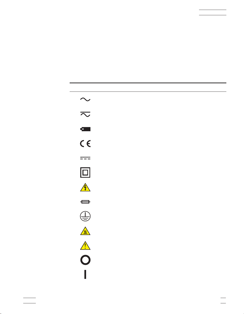
1.1 Symbols Used
Table 1 lists the International Electrical Symbols. Some or all of these symbols
may be used on the instrument or in this manual.
Table 1 International Electrical Symbols
Symbol Description
AC (Alternating Current)
AC-DC
Battery
CE Complies with European Union Directives
1 Before You Start
DC
Double Insulated
Electric Shock
Fuse
PE Ground
Hot Surface (Burn Hazard)
Read the User’s Manual (Important Information)
Off
On
5623A 1
Page 7

1 Before You Start
Symbol Description
Canadian Standards Association
CAT
OVERVOLTAGE (Installation) CATEGORY II, Pollution Degree 2 per IEC1010-1 refers to the
level of Impulse Withstand Voltage protection provided. Equipment of OVERVOLTAGE CATE
GORY II is energy-consuming equipment to be supplied from the fixed installation. Exam
ples include household, office, and laboratory appliances.
C-TIC Australian EMC Mark
1.2 Safety Information
Use this instrument only as specified in this manual. Otherwise, the protection
provided by the instrument may be impaired.
The following definitions apply to the terms “Warning” and “Caution”.
“Warning” identifies conditions and actions that may pose hazards to the user.
“Caution” identifies conditions and actions that may damage the instrument being used.
1.2.1
Warnings
To avoid personal injury, follow these guidelines.
• DO NOT use this instrument to measure the temperature of any hazard-
ous live component.
-
-
•
Use of this instrument at high temperatures for extended periods of time
can cause the handle to become hot.
•
Follow all safety guidelines listed in the user’s manual.
•
Calibration Equipment should only be used by Trained Personnel.
1.2.2
Cautions
To avoid possible damage to the instrument, follow these guidelines.
•
DO NOT drop or bang the probe in any way. This will cause damage to
the probe internally and affect its calibration.
•
Read Section 5 entitled “PRT Care and Handling Guidelines” before re
moving the PRT from the shipping box. Incorrect handling can damage
the PRT and void the warranty.
2 Hart Scientific
-
Page 8

Keep the shipping container in case it is necessary to ship the PRT. Incor
•
rect packaging of the PRT for shipment can cause irreparable damage.
1.3 Hart Scientific Authorized Service Centers
Please contact one of the following authorized Service Centers to coordinate
service on your Hart product:
Hart Scientific, Inc.
799 E. Utah Valley Drive
American Fork, UT 84003-9775
USA
Phone: +1.801.763.1600
Telefax: +1.801.763.1010
E-mail: support@hartscientific.com
Fluke Nederland B.V.
Customer Support Services
Science Park Eindhoven 5108
5692 EC Son
NETHERLANDS
1 Before You Start
-
Phone: +31-402-675300
Telefax: +31-402-675321
E-mail: ServiceDesk@fluke.nl
Fluke Int'l Corporation
Service Center - Instrimpex
Room 2301 Sciteck Tower
22 Jianguomenwai Dajie
Chao Yang District
Beijing 100004, PRC
CHINA
Phone: +86-10-6-512-3436
Telefax: +86-10-6-512-3437
E-mail: xingye.han@fluke.com.cn
5623A 3
Page 9

1 Before You Start
Fluke South East Asia Pte Ltd.
Fluke ASEAN Regional Office
Service Center
83 Clemenceau Avenue
#15-15/06 Ue Square
239920
SINGAPORE
Phone: +65-737-2922
Telefax: +65-737-5155
E-mail: antng@singa.fluke.com
When contacting these Service Centers for support, please have the following
information available:
Model Number
•
• Serial Number
• Complete description of the problem
4 Hart Scientific
Page 10

2 Introduction
2.1 General
The Platinum Resistance Thermometers (PRT) model 5623A is designed to be
a secondary standard interpolating instrument converting temperature to resis
tance. The 5623A assembly design allows for exposure to very cold tempera
ture (–200°C) and is an ideal reference for verification, monitoring or
calibrating control sensors in located in freezers or incubators. The 5623A may
also be used as a temperature standard for calibration of industrial sensors. The
PRT is used with a readout device to detect temperature changes or actual tem
perature. The 5623A covers the range from –200°C to 156°C. Standard length
is 6 inches. Custom lengths are available on request.
2.2 Recalibration
The recalibration of the 5623A PRT should be scheduled according to the
user’s company Quality Assurance requirements. Normally, a PRT is
recalibrated annually. Unless the PRT is used only over a limited range, calibration over the full range of the PRT (–200°C to 156°C) is recommended. For information on recalibrating your 5623A, contact an Authorized Hart Scientific
Service Center for an RMA number and current pricing (see Section 1.3).
2 Introduction
-
-
-
Depending on the user’s Quality Assurance requirements, the PRT drift should
be checked periodically at the Triple Point of Water (TPW). Section 7,Troubleshooting, provides information on drift with respect to mechanical shock and
oxidation.
5623A 5
Page 11

3 Specifications and Warranty
3.1 Specifications
See Table 2.
Table 2 Specifications
Temperature Range –200°C to 156°C
Entire Assembly Range –200°C to 156°C
Accuracy (Includes calibration
uncertainty and short-term
stability)
Long-term Drift (°C) <±0.01 at 0°C per year, when used periodically at 200
Hysteresis (°C) <0.01
Temperature Coefficient 0.003925 ohms/ohms/°C
Size (O.D.) 0.25" (6.35 mm)
Sheath Length 6" (152.4 mm)
Sheath Material Inconel 600
Cable length 20 ft. (609.6 cm)
Lead Wires 22 AWG/ Teflon insulated cable, 4-wire
±0.05°C (full range)
3 Specifications and Warranty
3.2 Warranty
Hart Scientific, Inc. (Hart) warrants this product to be free from defects in ma
terial and workmanship under normal use and service for a period as stated in
our current product catalog from the date of shipment. This warranty extends
only to the original purchaser and shall not apply to any product which, in
Hart’s sole opinion, has been subject to misuse, alteration, abuse or abnormal
conditions of operation or handling.
Software is warranted to operate in accordance with its programmed instruc
tions on appropriate Hart products. It is not warranted to be error free.
Hart’s obligation under this warranty is limited to repair or replacement of a
product which is returned to Hart within the warranty period and is determined,
upon examination by Hart, to be defective. If Hart determines that the defect or
malfunction has been caused by misuse, alteration, abuse or abnormal condi
tions or operation or handling, Hart will repair the product and bill the pur
chaser for the reasonable cost of repair.
5623A 7
-
-
-
-
Page 12

3 Specifications and Warranty
To exercise this warranty, the purchaser must forward the product after calling
or writing an Authorized Hart Scientific Service Center (see Section 1.3 on
page 3) for authorization. The Service Center assumes NO risk for in-transit
damage.
THE FOREGOING WARRANTY IS PURCHASER’S SOLE AND EXCLU
SIVE REMEDY AND IS IN LIEU OF ALL OTHER WARRANTIES, EX
-
PRESS OR IMPLIED, INCLUDING BUT NOT LIMITED TO ANY
IMPLIED WARRANTY OR MERCHANTABILITY, OR FITNESS FOR ANY
PARTICULAR PURPOSE OR USE. HART SHALL NOT BE LIABLE FOR
ANY SPECIAL, INDIRECT, INCIDENTAL, OR CONSEQUENTIAL DAM
-
AGES OR LOSS WHETHER IN CONTRACT, TORT, OR OTHERWISE.
8 Hart Scientific
Page 13

4 Installation
4.1 Lead Wire Identification
The 5623A PRT is equipped with a four-wire cable (see Figure 1). Four lead
wires are used to cancel lead wire resistance. For best results, the readout de
vice should be equipped to handle four-terminal resistors.
4 Installation
-
White
White
Figure 1 PRT Schematic
Red
Red
The lead wires are two different colors. Lead wire pairs attached to each end of
the sensor are identified by red and white insulation.
5623A 9
Page 14

5 PRT Care and Handling Guidelines
5.1 PRT Care
CAUTION: READ THIS SECTION BEFORE REMOVING THE PRT
FROM THE SHIPPING BOX OR CASE
Care must be taken in handling the PRT to maintain calibration accuracy. Care
should still be used when handling the PRT even though the Inconel sheath is
durable and provides good protection for the sensor. Correct handling of the
PRT will prolong the life expectancy. When not in use, the PRT should be
stored in an optional protective case that can be purchased from Hart Scientific.
The handle is designed to be immersed.
5.2 PRT Handling Guidelines
• DO keep the thermometer as clean as possible.
• DO immerse the thermometer in the appropriate liquid for the tempera-
ture range. If a dry block is used, the well diameter should allow the PRT
to comfortably slip in and out without excess movement. For best results,
immerse the thermometer as deep as possible to avoid “stem effect” (the
temperature error caused by the conduction of heat away from the sensor).
5 PRT Care and Handling Guidelines
•
DO allow sufficient time for the thermometer to stabilize before making
measurements. This allows for the best accuracy.
•
DO use the correct drive current with the thermometer to prevent error in
temperature or resistance. Hart Scientific recommends 1mA.
•
DO use the protective shipping box provided or other protection when the
thermometer is not in use.
•
DO NOT subject the thermometer to any physical shock or vibration.
•
DO NOT use pliers or other devices to squeeze the sheath. This action
can permanently damage the PRT.
•
DO NOT subject the thermometer to temperatures above the highest
specified operating temperature.
•
DO NOT expose the thermometer’s handle or cables to extreme tempera
tures. The temperature limits of the handle are: –200°C to 156°C
5623A 11
-
Page 15

5 PRT Care and Handling Guidelines
DO NOT screw a clamp down so tight that it dents the sheath. This can
•
permanently damage the PRT.
12 Hart Scientific
Page 16

6 Operation
6.1 General
For best results, be familiar with the operation of the heat source and the
read-out instrument. Be sure to follow the manufacturer’s instructions for the
read-out instrument and the heat source.
6.2 Immersion Requirements
Stem effect can cause measurement errors for any thermometer not immersed
in the fluid at least 114 mm (4.5 inches). This error is due to heat lost or gained
by the sensing element through the thermometer stem. In addition, heat losses
occur due to radiation losses from the sensing element to the housing.
The immersion depth for standards is dependent on several factors including
accuracy requirements and type of liquid. Therefore, we recommend a 114 mm
(4.5 inches) minimum immersion depth. However, remember the handle limitations. The handle is designed to be immersed. The temperature limits of the
handle are –200°C to 156°C. Temperatures outside these limits can damage the
handle and the probe. Convection of heat from the heat source must be kept
within the handle limits.
6 Operation
The exact immersion depth required can be determined by performing a gradient test taking measurements approximately every 1.27 cm (.5 inches) until
there is a significant difference in readings. Allow the thermometer to stabilize
at each new depth. Plot the results to see the stem effect.
6.3 Thermal EMF
Two factors contribute to thermal EMF, chemical consistency and physical con
sistency. Variations in chemical structure due to impurities can contribute to
thermal EMF. Also discrepancies in crystal structure can contribute to thermal
EMF. These factors are minimized by annealing the full length of wire before
construction of the PRT.
Likewise, connection to extension lead wires and readout instruments can be a
source of thermal EMF. The thermal EMF is caused by a difference in tempera
ture between two connections. If the two connections are the same temperature,
there will be little or no thermal EMF effects. However, if there is a substantial
temperature difference between connections, the thermal EMF effects will be
significant. Therefore, cover or insulate any exposed bridge or galvanometer
terminals to lessen the source of error. The effects of thermal EMF can be can
celed by using an AC bridge or a DC bridge with reversible current.
-
-
-
5623A 13
Page 17

7 Troubleshooting
7.1 Troubleshooting
In the event that the probe appears to function abnormally, this section may be
of use in solving the problem. Several possible problem conditions are de
scribed along with likely causes and solutions. If a problem arises, please read
this section carefully and attempt to understand and solve the problem. If the
probe seems faulty or the problem cannot otherwise be solved, contact an Au
thorized Hart Scientific Service Center (see Section 1.3) for assistance. Be sure
to have the model number and serial number of your probe available.
Problem Causes and Solutions
7 Troubleshooting
-
-
Data changes greater than 0.1°C
are observed
Data changes less than 0.1°C
Data unstable
Temperature readout different than
expected, e.g. the heat source is set
at 150°C, the PRT measures 125°C.
Mechanical shock can cause temperature errors as great as 0.5°C. If this
•
is observed, first measure and record the R
• Slight mechanical shock can cause temperature errors less than 0.1°C.
• If the data is unstable at the Triple Point of Water (TPW), check the con-
nector. If the connector is correct, contact an Authorized Hart Scientific
Service Center (see Section 1.3). The PRT may be damaged.
• If the data is unstable at high temperatures, it may be due to electrical
noise in the system. Reduce the temperature and observe the data. If it
is stable, electrical noise is interfering with the measurements at high
temperatures. Check the grounding of the readout device and the heat
source. A faulty ground on either device could interfere with high temperature measurements. A ground wire attached to the metal sheath of
the PRT may help to reduce electrical noise interference.
•
Measure the PRT resistance at TPW.
•
If the resistance of the PRT is less than the rated resistance, e.g. 70 Ω,
there may be a short in the sensor. Contact an Authorized Hart Scientific
Service Center (see Section 1.3).
•
If the resistance of the PRT is only a few ohms, there may be a short in
the four lead-wires. Contact an Authorized Hart Scientific Service Center
(see Section 1.3).
•
If the PRT is open, the resistance will be “Out of Limits” or in the
kilo-ohm or mega-ohm range. Contact an Authorized Hart Scientific Ser
vice Center (see Section 1.3).
tp.
-
5623A 15
 Loading...