

Page 1

5616
Hart Scientific
Platinum Resistance Thermometer
User’s Guide
Rev. 780801
Page 2

Limited Warranty & Limitation of Liability
Each product from Fluke Corporation, Hart Scientific Division (“Hart”) is warranted to be free from de
fects in material and workmanship under normal use and service. The warranty period is 1 year for the
Platinum Resistance Thermometer. The warranty period begins on the date of the shipment. Parts, prod
uct repairs, and services are warranted for 90 days. The warranty extends only to the original buyer or
end-user customer of a Hart authorized reseller, and does not apply to fuses, disposable batteries or to
any other product, which in Hart’s opinion, has been misused, altered, neglected, or damaged by accident
or abnormal conditions of operation or handling. Hart warrants that software will operate substantially in
accordance with its functional specifications for 90 days and that it has been properly recorded on
non-defective media. Hart does not warrant that software will be error free or operate without interrup
tion. Hart does not warrant calibrations on the Platinum Resistance Thermometer.
Hart authorized resellers shall extend this warranty on new and unused products to end-user customers
only but have no authority to extend a greater or different warranty on behalf of Hart. Warranty support is
available if product is purchased through a Hart authorized sales outlet or Buyer has paid the applicable
international price. Hart reserves the right to invoice Buyer for importation costs of repairs/replacement
parts when product purchased in one country is submitted for repair in another country.
Hart’s warranty obligation is limited, at Hart’s option, to refund of the purchase price, free of charge re
pair, or replacement of a defective product which is returned to a Hart authorized service center within
the warranty period.
To obtain warranty service, contact your nearest Hart authorized service center or send the product, with
a description of the difficulty, postage, and insurance prepaid (FOB Destination), to the nearest Hart authorized service center. Hart assumes no risk for damage in transit. Following warranty repair, the product will be returned to Buyer, transportation prepaid (FOB Destination). If Hart determines that the
failure was caused by misuse, alteration, accident or abnormal condition or operation or handling, Hart
will provide an estimate or repair costs and obtain authorization before commencing the work. Following
repair, the product will be returned to the Buyer transportation prepaid and the Buyer will be billed for
the repair and return transportation charges (FOB Shipping Point).
-
-
-
-
Rev. 780801
THIS WARRANTY IS BUYER’S SOLE AND EXCLUSIVE REMEDY AND IS IN LIEU OF ALL
OTHER WARRANTIES, EXPRESS OR IMPLIED, INCLUDING BUT NOT LIMITED TO ANY IM
PLIED WARRANTY OF MERCHANTABILITY OR FITNESS FOR A PARTICULAR PURPOSE.
HART SHALL NOT BE LIABLE FOR ANY SPECIAL, INDIRECT, INCIDENTAL. OR CONSE
QUENTIAL DAMAGES OR LOSSES, INCLUDING LOSS OF DATA, WHETHER ARISING FROM
BREACH OF WARRANTY OR BASED ON CONTRACT, TORT, RELIANCE OR ANY OTHER
THEORY.
Since some countries or states do not allow limitation of the term of an implied warranty, or exclusion or
limitation of incidental or consequential damages, the limitations and exclusions of this warranty may not
apply to every buyer. If any provision of this Warranty is held invalid or unenforceable by a court of com
petent jurisdiction, such holding will not affect the validity or enforceability of any other provision.
Fluke Corporation, Hart Scientific Division
799 E. Utah Valley Drive • American Fork, UT 84003-9775 • USA
Phone: +1.801.763.1600 • Telefax: +1.801.763.1010
E-mail: supporthartscientific.com
www.hartscientific.com
Subject to change without notice. • Copyright © 2006 • Printed in USA
-
-
-
Page 3

Table of Contents
1 Before You Start . . . . . . . . . . . . . . . . . . . . . . . . . . 1
1.1 Symbols Used . . . . . . . . . . . . . . . . . . . . . . . . . . . . 1
1.2 Safety Information . . . . . . . . . . . . . . . . . . . . . . . . . . 2
1.2.1 Warnings . . . . . . . . . . . . . . . . . . . . . . . . . . . . . . . . . . . . . 2
1.2.2 Cautions . . . . . . . . . . . . . . . . . . . . . . . . . . . . . . . . . . . . . 2
1.3 Authorized Service Centers. . . . . . . . . . . . . . . . . . . . . . 3
2 Introduction . . . . . . . . . . . . . . . . . . . . . . . . . . . . 5
2.1 General . . . . . . . . . . . . . . . . . . . . . . . . . . . . . . . . 5
2.2 Recalibration . . . . . . . . . . . . . . . . . . . . . . . . . . . . . 5
3 Specifications . . . . . . . . . . . . . . . . . . . . . . . . . . . . 7
4 Installation . . . . . . . . . . . . . . . . . . . . . . . . . . . . . 9
4.1 Lead Wire Identification . . . . . . . . . . . . . . . . . . . . . . . 9
5 PRT Care and Handling Guidelines. . . . . . . . . . . . . . . 11
5.1 PRT Care . . . . . . . . . . . . . . . . . . . . . . . . . . . . . . 11
5.2 PRT Handling Guidelines . . . . . . . . . . . . . . . . . . . . . . 11
6 Operation . . . . . . . . . . . . . . . . . . . . . . . . . . . . . 13
6.1 General . . . . . . . . . . . . . . . . . . . . . . . . . . . . . . . 13
6.2 Immersion Requirements . . . . . . . . . . . . . . . . . . . . . . 13
6.3 Thermal EMF . . . . . . . . . . . . . . . . . . . . . . . . . . . . 13
6.4 Transition Junction . . . . . . . . . . . . . . . . . . . . . . . . . 13
7 Troubleshooting. . . . . . . . . . . . . . . . . . . . . . . . . . 15
7.1 Troubleshooting . . . . . . . . . . . . . . . . . . . . . . . . . . . 15
i
Page 4
1 Before You Start
1.1 Symbols Used
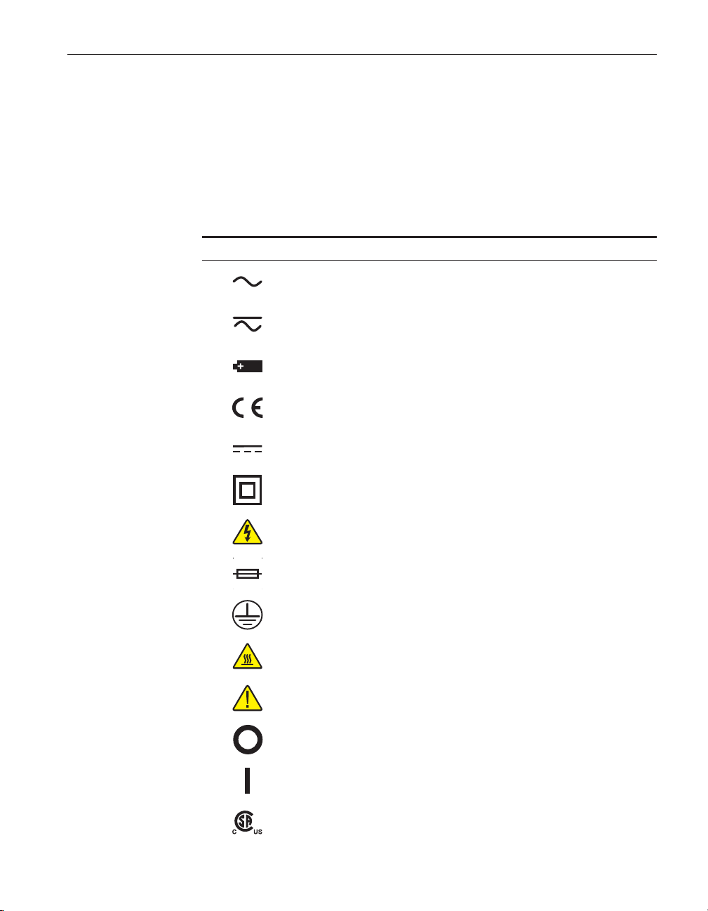
Table 1 lists the International Electrical Symbols. Some or all of these symbols
may be used on the instrument or in this guide.
Table 1 International Electrical Symbols
Symbol Description
AC (Alternating Current)
AC-DC
Battery
CE Complies with European Union Directives
1 Before You Start
Symbols Used
DC
Double Insulated
Electric Shock
Fuse
PE Ground
Hot Surface (Burn Hazard)
Read the User’s Manual (Important Information)
Off
On
Canadian Standards Association
1
Page 5
5616 PRT
User’s Guide
1.2 Safety Information
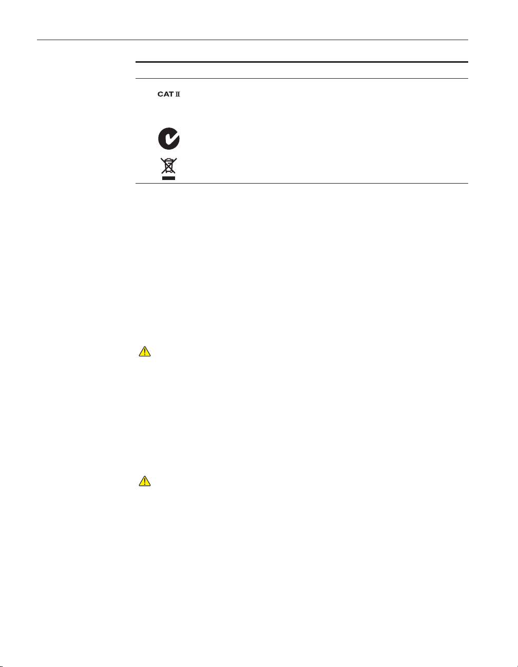
Symbol Description
OVERVOLTAGE (Installation) CATEGORY II, Pollution Degree 2 per IEC1010-1 re
fers to the level of Impulse Withstand Voltage protection provided. Equipment of
OVERVOLTAGE CATEGORY II is energy-consuming equipment to be supplied from
the fixed installation. Examples include household, office, and laboratory appliances.
C-TIC Australian EMC Mark
The European Waste Electrical and Electronic Equipment (WEEE) Directive
(2002/96/EC) mark.
-
Use this instrument only as specified in this guide. Otherwise, the protection
provided by the instrument may be impaired.
The following definitions apply to the terms “Warning” and “Caution”.
“Warning” identifies conditions and actions that may pose hazards to the user.
“Caution” identifies conditions and actions that may damage the instrument being used.
1.2.1
Warnings
To avoid personal injury, follow these guidelines.
• DO NOT use this instrument to measure the temperature of any hazardous
live component.
•
Use of this instrument at high temperatures for extended periods of time
can cause the handle to become hot.
•
Follow all safety guidelines listed in the user’s guide.
•
Calibration Equipment should only be used by Trained Personnel.
1.2.2
Cautions
To avoid possible damage to the instrument, follow these guidelines.
•
DO NOT drop or bang the probe in any way. This will cause damage to
the probe internally and affect its calibration.
•
Read Section entitled “PRT Care and Handling Guidelines” before re
moving the PRT from the shipping box. Incorrect handling can damage
the PRT and void the warranty.
•
Keep the shipping container in case it is necessary to ship the PRT. Incor
-
rect packaging of the PRT for shipment can cause irreparable damage.
2
Page 6

1.3 Authorized Service Centers
Please contact one of the following authorized Service Centers to coordinate
service on your Hart product:
Fluke Corporation, Hart Scientific Division
799 E. Utah Valley Drive
American Fork, UT 84003-9775
USA
Phone: +1.801.763.1600
Telefax: +1.801.763.1010
E-mail: supporthartscientific.com
Fluke Nederland B.V.
Customer Support Services
Science Park Eindhoven 5108
5692 EC Son
NETHERLANDS
1 Before You Start
Authorized Service Centers
Phone: +31-402-675300
Telefax: +31-402-675321
E-mail: ServiceDeskfluke.nl
Fluke Int'l Corporation
Service Center - Instrimpex
Room 2301 Sciteck Tower
22 Jianguomenwai Dajie
Chao Yang District
Beijing 100004, PRC
CHINA
Phone: +86-10-6-512-3436
Telefax: +86-10-6-512-3437
E-mail: xingye.hanfluke.com.cn
Fluke South East Asia Pte Ltd.
Fluke ASEAN Regional Office
Service Center
3
Page 7

5616 PRT
User’s Guide
60 Alexandra Terrace #03-16
The Comtech (Lobby D)
118502
SINGAPORE
Phone: +65 6799-5588
Telefax: +65 6799-5588
E-mail: antngsinga.fluke.com
When contacting these Service Centers for support, please have the following
information available:
Model Number
•
Serial Number
•
Complete description of the problem
•
4
Page 8

2 Introduction
2.1 General
The Platinum Resistance Thermometer (PRT) model 5616 is designed to be a
secondary standard interpolating instrument converting temperature to resis
tance. The 5616 may also be used as a temperature standard for calibration of
industrial sensors. The PRT is used with a readout device to detect temperature
changes or actual temperature.
2.2 Recalibration
The recalibration of the 5616 PRT should be scheduled according to the user’s
company Quality Assurance requirements. Normally, a PRT is recalibrated an
nually. Unless the PRT is used only over a limited range, calibration over the
full range of the PRT is recommended. For information on recalibrating your
5616, contact an Authorized Service Center for an RMA number and current
pricing (see Section 1.3, Authorized Service Centers).
Depending on the user’s Quality Assurance requirements, the PRT drift should
be checked periodically at the Triple Point of Water (TPW). Section 7, Troubleshooting, provides information on drift with respect to mechanical shock and
oxidation.
2 Introduction
General
-
-
5
Page 9

3 Specifications
Parameter Value
Temperature range –200 °C to 420 °C
Nominal resistance
at 0.01 °C
Temperature coefficient
[1]
Accuracy
Short-term repeatability
[3]
Drift
Hysteresis ± 0.010 °C maximum
Sensor length 50.8 mm (2.0 in)
Sensor location 9.5 mm ± 3.2 mm from tip (0.375 in ± 0.125 in)
Sheath dimensions, length x
diameter
Sheath diameter tolerance ±0.08mm(±0.003in)
Sheath material Inconel™600
Minimum insulation
resistance
Transition junction
temperature range
Transition junction
dimensions
Minimum immersion length
(< 5 mK error)
Maximum immersion length 254 mm (10 in)
Response time
Self heating (in 0 °C bath) 60 mW/°C
Lead-wire cable type Te fl o n™jacketed cable, Teflon insulated conductors, 24 AWG
Lead-wire length 182.9 cm ± 2.5 cm (72.0 in ± 1.0 in)
Lead-wire temperature range –50 °C to 150 °C
Calibration NIST-traceable calibration
[1]
"Accuracy" is a difficult term when used to describe a resistance thermometer. The simplest way to de
rive basic “accuracy” is to combine the probe drift specification and calibration uncertainty with readout
accuracy at a given temperature.
[2]
Three thermal cycles from min to max temp, includes hysteresis, 99.8 % confidence
[3]
After 100 hrs at max temp, 99.8 % confidence
[4]
Temperatures outside this range will cause irreparable damage. For best performance, transition junc
tion should not be too hot to touch.
[5]
Per ASTM E 644
[2]
[4]
[5]
[5]
Ω
±0.5
100
0.003925
Ω
Ω/Ω
/°C nominal
See footnote
± 0.010 °C at 0.010 °C
± 0.010 °C at 0.010 °C
298.45 mm x 6.35 mm (11.750 in x 0.250 in)
Ω
at 23 °C
500 M
–50 °C to 150 °C
76.2 mm x 9.5 mm (3.00 in x 0.375 in)
102 mm (4.0 in)
8 seconds typical
stranded, silver plated copper
3 Specifications
-
-
7
Page 10

4 Installation
White
Red
White
Red
4.1 Lead Wire Identification
The 5616 PRT is equipped with a four-wire cable (see Figure 1). Four lead
wires are used to cancel lead wire resistance. For best results, the readout de
vice should be equipped to handle four-terminal resistors.
The lead wires are two different colors. Lead wire pairs attached to each end of
the sensor are identified by red and white insulation.
Figure 1 PRT Schematic
Lead Wire Identification
4 Installation
-
9
Page 11

5 PRT Care and Handling Guidelines
5 PRT Care and Handling Guidelines
5.1 PRT Care
CAUTION: READ THIS SECTION BEFORE REMOVING THE PRT
FROM THE SHIPPING BOX OR CASE
Care must be taken in handling the PRT to maintain calibration accuracy. Care
should still be used when handling the PRT even though the Inconel sheath is
durable and provides good protection for the sensor. Correct handling of the
PRT will prolong the life expectancy. When not in use, the PRT should be
stored in an optional protective case that can be purchased by contacting an Au
thorized Service Center (see section 1.3, Authorized Service Centers).
The handle is not designed to be immersed.
5.2 PRT Handling Guidelines
• DO keep the thermometer as clean as possible.
• DO immerse the thermometer in the appropriate liquid for the tempera-
ture range. If a dry block is used, the well diameter should allow the PRT
to comfortably slip in and out without excess movement. For best results,
immerse the thermometer as deep as possible to avoid “stem effect” (the
temperature error caused by the conduction of heat away from the
sensor).
• DO allow sufficient time for the thermometer to stabilize before making
measurements. This allows for the best accuracy.
•
DO use the correct drive current with the thermometer to prevent error in
temperature or resistance. Hart Scientific recommends 1mA.
•
DO use the protective shipping box provided or other protection when the
thermometer is not in use.
•
DO NOT subject the thermometer to any physical shock or vibration.
•
DO NOT use pliers or other devices to squeeze the sheath. This action can
permanently damage the PRT.
•
DO NOT subject the thermometer to temperatures above the highest spec
ified operating temperature.
•
DO NOT expose the thermometer’s handle or cables to extreme tempera
tures.
•
DO NOT screw a clamp down so tight that it dents the sheath. This can
permanently damage the PRT.
PRT Care
-
-
-
11
Page 12

6 Operation
6.1 General
6 Operation
General
For best results, be familiar with the operation of the heat source and the read
out instrument. Be sure to follow the manufacturer’s instructions for the read
out instrument and the heat source.
6.2 Immersion Requirements
Stem effect can cause measurement errors for any thermometer. This error is
due to heat lost or gained by the sensing element through the thermometer
stem. In addition, heat losses occur due to radiation losses from the sensing ele
ment to the housing.
The immersion depth for standards is dependent on several factors including
accuracy requirements and type of liquid. However, remember the handle limi
tations. The handle is not designed to be immersed.
The exact immersion depth required can be determined by performing a gradient test taking measurements approximately every 1.27 cm (0.50 inches) until
there is a significant difference in readings. Allow the thermometer to stabilize
at each new depth. Plot the results to see the stem effect.
6.3 Thermal EMF
Two factors contribute to thermal EMF, chemical consistency and physical consistency. Variations in chemical structure due to impurities can contribute to
thermal EMF. Also discrepancies in crystal structure can contribute to thermal
EMF. These factors are minimized by annealing the full length of wire before
construction of the PRT.
Likewise, connection to extension lead wires and readout instruments can be a
source of thermal EMF. The thermal EMF is caused by a difference in tempera
ture between two connections. If the two connections are the same temperature,
there will be little or no thermal EMF effects. However, if there is a substantial
temperature difference between connections, the thermal EMF effects will be
significant. Therefore, cover or insulate any exposed bridge or galvanometer
terminals to lessen the source of error. The effects of thermal EMF can be can
celed by using an AC bridge or a DC bridge with reversible current.
-
-
-
-
-
-
6.4 Transition Junction
Exceeding the temperature range of the transition junction will cause a breach
in the seal of the instrument. Maintaining the seal is critical to preventing mois
ture from entering the device. If moisture penetrates the seal, the PRT's short
term repeatability, hysteresis, and insulation resistance may be adversely af
fected. Insulation resistance also decreases rapidly as the transition junction
-
-
13
Page 13

5616 PRT
User’s Guide
temperature increases, even if the seal is not broken. When the insulation resis
tance becomes sufficiently low, performance suffers. A good rule of thumb is
that the transition junction is too hot when it is hot enough to burn your thumb.
-
14
Page 14

7 Troubleshooting
7.1 Troubleshooting
In the event that the probe appears to function abnormally, this section may be
of use in solving the problem. Several possible problem conditions are de
scribed along with likely causes and solutions. If a problem arises, please read
this section carefully and attempt to understand and solve the problem. If the
probe seems faulty or the problem cannot otherwise be solved, contact an Au
thorized Service Center (see Section 1.3) for assistance. Be sure to have the
model number and serial number of your probe available.
7 Troubleshooting
Troubleshooting
-
-
Problem
Data changes greater than 0.1°C
are observed
Data changes less than 0.1°C
Data unstable
Temperature readout different
than expected, e.g. the heat
source is set at 150°C, the PRT
measures 125°C.
Causes and Solutions
Mechanical shock can cause temperature errors as great as 0.5°C. If
this is observed, first measure and record the Rtpw.
Slight mechanical shock can cause temperature errors less than
0.1°C.
If the data is unstable at the Triple Point of Water (TPW), check connections for evidence of a bad connection. If the connector appears
to be in good condition and the connections are good, the PRT may
be damaged. Contact an Authorized Service Center (see Section
1.3).
• If the data is unstable at high temperatures, it may be
due to electrical noise in the system. Reduce the temperature and observe the data. If it is stable, electrical
noise is interfering with the measurements at high temperatures. Also, this is usually due to low shunt resistance. The resistance between the leads and the sheath
(shunt resistance or insulation resistance) as measured
by a resistance meter should be greater than 500 meg
ohms at room temperature. Check the grounding of the
readout device and the heat source. A faulty ground on
either device could interfere with high temperature mea
surements. A ground wire attached to the metal sheath
of the PRT may help to reduce electrical noise interfer
ence.
Measure the PRT resistance at TPW.
•
If the resistance of the PRT is less than the rated resis
tance, e.g. 98 ohms for a 100 ohm PRT, there may be a
short in the sensor.
•
If the resistance of the PRT is only a few ohms, there
may be a short in the four lead-wires.
•
If the PRT is open, the resistance will be “Out of Limits”
or in the kilohm or megohm range.
For more information or assistance, contact an Authorized Service
Center (see Section 1.3).
-
-
-
-
15
 Loading...