

Page 1

5522A
Multi-Product Calibrator
January 2011
© 2011 Fluke Corporation. All rights reserved. Printed in USA. Specifications are subject to change without notice.
All product names are trademarks of their respective companies.
Operators Manual
Page 2

LIMITED WARRANTY AND LIMITATION OF LIABILITY
Each Fluke product is warranted to be free from defects in material and workmanship under
normal use and service. The warranty period is one year and begins on the date of shipment.
Parts, product repairs, and services are warranted for 90 days. This warranty extends only to the
original buyer or end-user customer of a Fluke authorized reseller, and does not apply to fuses,
disposable batteries, or to any product which, in Fluke's opinion, has been misused, altered,
neglected, contaminated, or damaged by accident or abnormal conditions of operation or
handling. Fluke warrants that software will operate substantially in accordance with its functional
specifications for 90 days and that it has been properly recorded on non-defective media. Fluke
does not warrant that software will be error free or operate without interruption.
Fluke authorized resellers shall extend this warranty on new and unused products to end-user
customers only but have no authority to extend a greater or different warranty on behalf of Fluke.
Warranty support is available only if product is purchased through a Fluke authorized sales outlet
or Buyer has paid the applicable international price. Fluke reserves the right to invoice Buyer for
importation costs of repair/replacement parts when product purchased in one country is submitted
for repair in another country.
Fluke's warranty obligation is limited, at Fluke's option, to refund of the purchase price, free of
charge repair, or replacement of a defective product which is returned to a Fluke authorized
service center within the warranty period.
To obtain warranty service, contact your nearest Fluke authorized service center to obtain return
authorization information, then send the product to that service center, with a description of the
difficulty, postage and insurance prepaid (FOB Destination). Fluke assumes no risk for damage in
transit. Following warranty repair, the product will be returned to Buyer, transportation prepaid
(FOB Destination). If Fluke determines that failure was caused by neglect, misuse, contamination,
alteration, accident, or abnormal condition of operation or handling, including overvoltage failures
caused by use outside the product’s specified rating, or normal wear and tear of mechanical
components, Fluke will provide an estimate of repair costs and obtain authorization before
commencing the work. Following repair, the product will be returned to the Buyer transportation
prepaid and the Buyer will be billed for the repair and return transportation charges (FOB
Shipping Point).
THIS WARRANTY IS BUYER'S SOLE AND EXCLUSIVE REMEDY AND IS IN LIEU OF ALL
OTHER WARRANTIES, EXPRESS OR IMPLIED, INCLUDING BUT NOT LIMITED TO ANY
IMPLIED WARRANTY OF MERCHANTABILITY OR FITNESS FOR A PARTICULAR PURPOSE.
FLUKE SHALL NOT BE LIABLE FOR ANY SPECIAL, INDIRECT, INCIDENTAL, OR
CONSEQUENTIAL DAMAGES OR LOSSES, INCLUDING LOSS OF DATA, ARISING FROM
ANY CAUSE OR THEORY.
Since some countries or states do not allow limitation of the term of an implied warranty, or
exclusion or limitation of incidental or consequential damages, the limitations and exclusions of
this warranty may not apply to every buyer. If any provision of this Warranty is held invalid or
unenforceable by a court or other decision-maker of competent jurisdiction, such holding will not
affect the validity or enforceability of any other provision.
Fluke Corporation
P.O. Box 9090
Everett, WA 98206-9090
U.S.A.
Fluke Europe B.V.
P.O. Box 1186
5602 BD Eindhoven
The Netherlands
11/99
Page 3

OPERATOR SAFETY
SUMMARY
WARNING
HIGH VOLTAGE
is used in the operation of this equipment
LETHAL VOLTAGE
may be present on the terminals, observe all safety precautions!
To avoid electrical shock hazard, the operator should not electrically contact
the output HI or sense HI terminals or circuits connected to these terminals.
During operation, lethal voltages of up to 1020 V ac or dc may be present on
these terminals.
Whenever the nature of the operation permits, keep one hand away from
equipment to reduce the hazard of current flowing through vital organs of
the body.
Page 4

Page 5

Table of Contents
Chapter Title Page
1 Introduction and Specifications......................................................... 1-1
Introduction........................................................................................................ 1-3
Safety Information ............................................................................................. 1-4
Overload Protection ........................................................................................... 1-5
Operation Overview........................................................................................... 1-5
Local Operation ............................................................................................. 1-5
Remote Operation (RS-232).......................................................................... 1-6
Remote Operation (IEEE-488) ...................................................................... 1-6
Where to Go from Here ..................................................................................... 1-7
Instruction Manuals ........................................................................................... 1-7
5522A Getting Started Manual...................................................................... 1-7
5522A Operators Manual .............................................................................. 1-7
General Specifications ....................................................................................... 1-8
Detailed Specifications ...................................................................................... 1-9
DC Voltage.................................................................................................... 1-9
DC Current .................................................................................................... 1-9
Resistance...................................................................................................... 1-11
AC Voltage (Sine Wave)............................................................................... 1-12
AC Current (Sine Wave) ............................................................................... 1-14
Capacitance.................................................................................................... 1-16
Temperature Calibration (Thermocouple)..................................................... 1-17
Temperature Calibration (RTD) .................................................................... 1-18
DC Power Specification Summary................................................................ 1-18
AC Power (45 Hz to 65 Hz) Specification Summary, PF=1 ......................... 1-19
Power and Dual Output Limit Specifications................................................ 1-19
Phase.............................................................................................................. 1-20
Additional Specifications................................................................................... 1-21
Frequency ...................................................................................................... 1-21
Harmonics (2
AC Voltage (Sine Wave) Extended Bandwidth ............................................ 1-22
AC Voltage (Non-Sine Wave)....................................................................... 1-22
AC Voltage, DC Offset ................................................................................. 1-24
AC Voltage, Square Wave Characteristics.................................................... 1-24
AC Voltage, Triangle Wave Characteristics ................................................. 1-24
nd
to 50th) .................................................................................. 1-21
i
Page 6

5522A
Operators Manual
AC Current (Non-Sine Wave) ....................................................................... 1-24
AC Current, Square Wave Characteristics .................................................... 1-25
AC Current, Triangle Wave Characteristics.................................................. 1-25
2 Preparing for Operations.................................................................... 2-1
Introduction........................................................................................................ 2-3
Unpack and Inspect............................................................................................ 2-3
How to Replace the Mains Power Fuse ............................................................. 2-3
How to Select Line Voltage............................................................................... 2-4
How to Connect to Line Power.......................................................................... 2-4
How to Select Line Frequency........................................................................... 2-4
How to Contact Fluke ........................................................................................ 2-6
Placement........................................................................................................... 2-7
Cooling Considerations...................................................................................... 2-7
3 Features ............................................................................................... 3-1
Introduction........................................................................................................ 3-3
Front-Panel Features .......................................................................................... 3-3
Rear-Panel Features ........................................................................................... 3-3
Softkey Menu Trees........................................................................................... 3-3
4 Front Panel Operation......................................................................... 4-1
Introduction........................................................................................................ 4-3
How to Turn on the Calibrator........................................................................... 4-3
Warming up the Calibrator ................................................................................ 4-4
How to Use the Softkeys ................................................................................... 4-4
How to Use the Setup Menu .............................................................................. 4-4
How to Use the Instrument Setup Menu ....................................................... 4-5
Utility Functions Menu.................................................................................. 4-6
How to Use the NV Memory Menu .............................................................. 4-6
How to Reset the Calibrator............................................................................... 4-7
How to Zero the Calibrator................................................................................ 4-7
Operate and Standby Modes .............................................................................. 4-8
How to Connect the Calibrator to a UUT .......................................................... 4-8
Recommended Cable and Connector Types.................................................. 4-9
When to Use EARTH and EXGRD .............................................................. 4-9
Earth .......................................................................................................... 4-9
External Guard .......................................................................................... 4-10
Four-Wire versus Two-Wire Connections .................................................... 4-10
Four-Wire Connection .............................................................................. 4-10
Two-Wire Compensation .......................................................................... 4-10
Compensation Off ..................................................................................... 4-10
Cable Connections Instructions..................................................................... 4-10
RMS Versus p-p Amplitude............................................................................... 4-16
Auto Range Versus Locked Range .................................................................... 4-17
How to Set Output ............................................................................................. 4-17
How to Set DC Voltage Output..................................................................... 4-18
How to Set AC Voltage Output..................................................................... 4-19
How to Set DC Current Output ..................................................................... 4-22
How to Set AC Current Output ..................................................................... 4-23
How to Set DC Power Output ....................................................................... 4-24
How to Set AC Power Output ....................................................................... 4-26
How to Set a Dual DC Voltage Output ......................................................... 4-29
How to Set a Dual AC Voltage Output
ii
......................................................... 4-30
Page 7

Contents (continued)
How to Set Resistance Output....................................................................... 4-33
How to Set Capacitance Output..................................................................... 4-34
How to Set Temperature Simulation (Thermocouple) .................................. 4-35
How to Set Temperature Simulation (RTD).................................................. 4-38
How to Measure Thermocouple Temperatures ............................................. 4-39
Waveform Types................................................................................................ 4-41
Sine Wave...................................................................................................... 4-41
Triangle Waves.............................................................................................. 4-42
Square Wave.................................................................................................. 4-42
Truncated Sine Wave .................................................................................... 4-43
How to Set Harmonics....................................................................................... 4-43
How to Adjust the Phase.................................................................................... 4-44
How to Enter a Phase Angle.......................................................................... 4-46
How to Enter a Power Factor ........................................................................ 4-46
How to Enter a DC Offset.................................................................................. 4-47
Editing and Error Output Settings...................................................................... 4-48
How to Edit the Output Setting ..................................................................... 4-48
How to Display the UUT Error ..................................................................... 4-48
How to Use Multiply and Divide .................................................................. 4-50
How to Set Output Limits.................................................................................. 4-50
How to Set Voltage and Current Limits ........................................................ 4-50
How to Measure Pressure .................................................................................. 4-51
How to Synchronize the Calibrator using 10 MHz IN/OUT ............................. 4-52
How to Use an External 10 MHz Clock ........................................................ 4-52
How to Source AC Current and Parallel-Connected 5522As........................ 4-53
Three-Phase Power Calibration..................................................................... 4-54
Sample Applications .......................................................................................... 4-55
How Calibrate an 80 Series Digital Multimeter ............................................ 4-55
Cables........................................................................................................ 4-56
EARTH Connection .................................................................................. 4-56
How to Test the Meter............................................................................... 4-56
How to Calibrate the Meter....................................................................... 4-60
How to Test a Model 41 Power Harmonics Analyzer................................... 4-60
How to Test Watts, VA, VAR Performance ............................................. 4-60
How to Test Harmonics Volts Performance ............................................. 4-62
How to Test Harmonics Amps Performance............................................. 4-63
How to Calibrate a Fluke 51 Thermometer ................................................... 4-64
How to Test the Thermometer .................................................................. 4-64
How to Calibrate the Thermometer........................................................... 4-65
5 Remote Operations ............................................................................. 5-1
Introduction........................................................................................................ 5-3
How to Set up the IEEE-488 Port for Remote Control...................................... 5-5
IEEE-488 Port Setup Procedure .................................................................... 5-7
How to Test the IEEE-488 Port..................................................................... 5-7
How to Set up the RS-232 Host Port for Remote Control................................. 5-9
RS-232 Host Port Setup Procedure ............................................................... 5-9
How to Test the RS-232 Host Port ................................................................ 5-11
How to Test RS-232 Host Port Operation with a Terminal ...................... 5-12
How to Test RS-232 Host Port Operation with Visual Basic ................... 5-14
How to Set up the RS-232
RS-232 UUT Port Setup Procedure............................................................... 5-15
How to Test the RS-232 UUT Port via RS-232 Host Port ............................ 5-16
How to Test RS-232 UUT Port Operation via a Terminal........................ 5-17
How to Test RS-232 UUT Port Operation with Visual Basic................... 5-18
iii
UUT Port for Remote Control ................................ 5-15
Page 8

5522A
Operators Manual
How to Test the RS-232 UUT Port via IEEE-488 Port................................. 5-18
How to Change between Remote and Local Operation..................................... 5-20
Local State..................................................................................................... 5-20
Local with Lockout State............................................................................... 5-20
Remote State.................................................................................................. 5-20
Remote with Lockout State ........................................................................... 5-21
RS-232 Interface Overview ............................................................................... 5-21
IEEE-488 Interface Overview............................................................................ 5-22
How to Use Commands ..................................................................................... 5-25
Types of Commands...................................................................................... 5-25
Device-Dependent Commands.................................................................. 5-25
Common Commands................................................................................. 5-25
Query Commands...................................................................................... 5-25
Interface Messages (IEEE-488) ................................................................ 5-26
Compound Commands .................................................................................. 5-27
Coupled Commands .................................................................................. 5-28
Overlapped Commands............................................................................. 5-28
Sequential Commands............................................................................... 5-29
Commands that Require the Calibration Switch ....................................... 5-29
Commands for RS-232 Only..................................................................... 5-29
Commands for IEEE-488 Only................................................................. 5-30
Command Syntax .......................................................................................... 5-30
Parameter Syntax Rules ............................................................................ 5-30
Extra Space or Tab Characters .................................................................. 5-32
Terminators ............................................................................................... 5-32
Incoming Character Processing................................................................. 5-33
Response Message Syntax ........................................................................ 5-33
Checking 5522A Status ..................................................................................... 5-34
Serial Poll Status Byte (STB) ........................................................................ 5-35
Service Request (SRQ) Line ..................................................................... 5-37
Service Request Enable Register (SRE).................................................... 5-37
Programming the STB and SRE................................................................ 5-37
Event Status Register (ESR).......................................................................... 5-38
Event Status Enable (ESE) Register.......................................................... 5-38
Bit Assignments for the ESR and ESE...................................................... 5-38
Programming the ESR and ESE................................................................ 5-39
Instrument Status Register (ISR)................................................................... 5-40
Instrument Status Change Registers.......................................................... 5-40
Instrument Status Change Enable Registers.............................................. 5-40
Bit Assignments for the ISR, ISCR, and ISCE ......................................... 5-40
Programming the ISR, ISCR, and ISCE ................................................... 5-41
Output Queue................................................................................................. 5-42
Error Queue ................................................................................................... 5-42
Remote Program Examples................................................................................ 5-42
Guidelines for Programming the Calibrator .................................................. 5-42
Writing an SRQ and Error Handler ............................................................... 5-43
Verifying a Meter in the IEEE-488 Bus ........................................................ 5-44
Verifying a Meter on the RS-232 UUT Serial Port ....................................... 5-44
Using *OPC?, *OPC, and *WAI................................................................... 5-44
Taking a Thermocouple Measurement .......................................................... 5-45
Taking a Pressure Measurement.................................................................... 5-45
Using the RS-232 UUT Port to Contr
ol an Instrument ................................. 5-46
Input Buffer Operation .................................................................................. 5-46
6 Remote Commands............................................................................. 6-1
iv
Page 9

Contents (continued)
Introduction........................................................................................................ 6-3
Command Summary by Function ...................................................................... 6-3
Commands ......................................................................................................... 6-10
7 Maintenance......................................................................................... 7-1
Introduction........................................................................................................ 7-3
How to Replace the Line Fuse ........................................................................... 7-3
How to Replace the Current Fuses..................................................................... 7-4
How to Clean the Air Filter ............................................................................... 7-5
General Cleaning ............................................................................................... 7-6
Performance Tests.............................................................................................. 7-7
8 Accessories ......................................................................................... 8-1
Introduction........................................................................................................ 8-3
Rack Mount Kit ................................................................................................. 8-4
IEEE-488 Interface Cable.................................................................................. 8-4
RS-232 Null-Modem Cables.............................................................................. 8-4
5520A-525A/LEADS ........................................................................................ 8-4
9 SC600 Oscilloscope Calibration Option............................................ 9-1
Introduction........................................................................................................ 9-3
SC600 Oscilloscope Calibration Option Specifications .................................... 9-3
General Specifications ....................................................................................... 9-4
Voltage Function Specifications.................................................................... 9-4
Edge Specifications ....................................................................................... 9-4
Leveled Sine Wave Specifications ................................................................ 9-5
Time Marker Specifications .......................................................................... 9-5
Wave Generator Specifications ..................................................................... 9-5
Pulse Generator Specifications...................................................................... 9-6
Trigger Signal Specifications (Pulse Function)............................................. 9-6
Trigger Signal Specifications (Time Marker Function) ................................ 9-6
Trigger Signal Specifications (Edge Function) ............................................. 9-6
Trigger Signal Specifications (Square Wave Voltage Function)................... 9-6
Trigger Signal Specifications ........................................................................ 9-6
Oscilloscope Input Resistance Measurement Specifications......................... 9-6
Oscilloscope Input Capacitance Measurement Specifications ...................... 9-6
Overload Measurement Specifications.......................................................... 9-7
Oscilloscope Connections.................................................................................. 9-7
How to Start the SC600 Option ......................................................................... 9-7
The Output Signal.......................................................................................... 9-8
How to Adjust the Output Signal .................................................................. 9-8
How to Key in a Value.............................................................................. 9-8
How to Adjust Values with the Rotary Knob ........................................... 9-9
X
and
D
How to Use
....................................................................... 9-10
How to Reset the Oscilloscope Option.......................................................... 9-10
How to Calibrat the Voltage Amplitude on an Oscilloscope............................. 9-10
The Volt Function.......................................................................................... 9-10
The V/DIV Menu .......................................................................................... 9-11
Shortcuts to Set the Voltage Amplitude ........................................................ 9-11
Amplitude Calibration Procedure for an Oscillosope.................................... 9-11
How to Calibrate the Pulse and Frequency Response on an Oscilloscope ........ 9-12
The Edge Function ........................................................................................ 9-13
Pulse Response Calibration Procedure for an Oscilloscope .......................... 9-13
Pulse Response Calibration with a Tunnel Diode Pulser .............................. 9-14
v
Page 10

5522A
Operators Manual
The Leveled Sine Wave Function ................................................................. 9-15
Shortcuts for Setting the Frequency and Voltage.......................................... 9-16
The MORE OPTIONS Menu ........................................................................ 9-16
How to Sweep Through a Frequency Range ................................................. 9-17
Frequency Response Calibration Procedure for an Oscilloscope.................. 9-18
How to Calibrate the Time Base of an Oscilloscope ......................................... 9-19
The Time Marker Function ........................................................................... 9-19
Time Base Marker Calibration Procedure for an Oscilloscope ..................... 9-20
How to Test the Trigger SC600 Option............................................................. 9-21
How to Test Video Triggers .............................................................................. 9-22
How to Verify Pulse Capture............................................................................. 9-23
How to Measure Input Resistance and Capacitance .......................................... 9-24
Input Impedance Measurement ..................................................................... 9-24
Input Capacitance Measurement ................................................................... 9-24
How to Test Overload Protection ...................................................................... 9-25
Remote Commands and Queries........................................................................ 9-26
General Commands ....................................................................................... 9-26
Edge Function Commands ............................................................................ 9-30
Marker Function Commands......................................................................... 9-30
Video Function Commands........................................................................... 9-31
Overload Function Commands...................................................................... 9-31
Impedance/Capacitance Function Commands............................................... 9-32
Verification Tables ............................................................................................ 9-33
DC Voltage Verification................................................................................ 9-33
AC Voltage Amplitude Verification.............................................................. 9-34
AC Voltage Frequency Verification.............................................................. 9-35
Wave Generator Amplitude Verification: 1 MΩ Output Impedance ............ 9-35
Wave Generator Amplitude Verification: 50 Ω Output Impedance.............. 9-37
Leveled Sine Wave Verification: Amplitude ................................................ 9-38
Leveled Sine Wave Verification: Frequency................................................. 9-39
Leveled Sine Wave Verification: Harmonics................................................ 9-39
Leveled Sine Wave Verification: Flatness .................................................... 9-40
Edge Verification: Amplitude ....................................................................... 9-48
Edge Verification: Frequency........................................................................ 9-48
Edge Verification: Duty Cycle ...................................................................... 9-49
Edge Verification: Rise Time........................................................................ 9-49
Tunnel Diode Pulser Verification.................................................................. 9-49
Marker Generator Verification ...................................................................... 9-50
Pulse Generator Verification: Period............................................................. 9-50
Pulse Generator Verification: Pulse Width ................................................... 9-50
Input Impedance Verification: Resistance..................................................... 9-51
Input Impedance Verification: Capacitance .................................................. 9-51
10 SC1100 Oscilloscope Calibration Option.......................................... 10-1
Introduction........................................................................................................ 10-3
SC1100 Option Specifications........................................................................... 10-3
General Specifications ....................................................................................... 10-3
Volt Specifications ........................................................................................ 10-4
Edge Specifications
Leveled Sine Wave Specifications ................................................................ 10-5
Time Marker Specifications .......................................................................... 10-6
Wave Generator Specifications ..................................................................... 10-6
Pulse Generator Specifications...................................................................... 10-7
Trigger Signal Specifications (Pulse Function)............................................. 10-7
Trigger Signal Specifications (Time Marker Function) ................................ 10-7
vi
....................................................................................... 10-5
Page 11

Contents (continued)
Trigger Signal Specifications (Edge Function) ............................................. 10-7
Trigger Signal Specifications (Square Wave Voltage Function)................... 10-7
TV Trigger Signal Specifications.................................................................. 10-7
Oscilloscope Input Resistance Measurement Specifications......................... 10-7
Oscilloscope Input Capacitance Measurement Specifications ...................... 10-8
Overload Measurement Specifications.......................................................... 10-8
Oscilloscope Connections.................................................................................. 10-8
How to Start the SC1100 Option ....................................................................... 10-8
The Output Signal.......................................................................................... 10-9
How to Adjust the Output Signal .................................................................. 10-9
How to Key in a Value.............................................................................. 10-9
How to Adjust Values with the Rotary Knob ........................................... 10-10
X
and
D
How to Use
....................................................................... 10-11
How to Reset the SC1100 Option.................................................................. 10-11
How to Calibrate the Voltage Amplitude on an Oscilloscope ........................... 10-11
The VOLT Function ...................................................................................... 10-11
The V/DIV Menu .......................................................................................... 10-12
Oscilloscope Amplitude Calibration Procedure ............................................ 10-12
How to Calibrate the Pulse and Frequency Response on an Oscilloscope ........ 10-13
The Edge Function ........................................................................................ 10-14
Oscilloscope Pulse Response Calibration Procedure .................................... 10-14
Pulse Response Calibration Using a Tunnel Diode Pulser............................ 10-15
The Leveled Sine Wave Function ................................................................. 10-16
Shortcuts for Setting the Frequency and Voltage.......................................... 10-17
The MORE OPTIONS Menu ........................................................................ 10-17
How to Sweep Through a Frequency Range ................................................. 10-18
Oscilloscope Frequency Response Calibration Procedure ............................ 10-19
How to Calibrate the Time Base of an Oscilloscope ......................................... 10-20
The Time Marker Function ........................................................................... 10-21
Time Base Marker Calibration Procedure for an Oscilloscope ..................... 10-22
How to Test the Trigger functions of an oscilloscope ....................................... 10-22
How to Test Video Triggers .............................................................................. 10-24
How to Verify Pulse Capture............................................................................. 10-25
How to Measure Input Resistance and Capacitance .......................................... 10-26
Input Impedance Measurement ..................................................................... 10-26
Input Capacitance Measurement ................................................................... 10-27
How to Test Overload Protection ...................................................................... 10-27
Remote Commands and Queries........................................................................ 10-28
General Commands ....................................................................................... 10-28
Edge Function Commands ............................................................................ 10-32
Marker Function Commands......................................................................... 10-32
Video Function Commands........................................................................... 10-33
Overload Function Commands...................................................................... 10-33
Impedance/Capacitance Function Commands............................................... 10-34
Verification Tables ............................................................................................ 10-35
DC Voltage Verification................................................................................ 10-35
AC Voltage Verification................................................................................ 10-37
AC Voltage Frequency Verification.............................................................. 10-38
Wave Generator Amplitude Verification: 1 MΩ Output Impedance ............ 10-39
Wave Generator Amplitude Verification: 50 Ω Output Impedance.............. 10-40
Edge Verification: Amplitude ....................................................................... 10-41
Edge Verification: Frequency........................................................................ 10-42
Edge Verification: Duty Cycle ...................................................................... 10-42
Edge Verification: Rise Time........................................................................ 10-42
Tunnel Diode Pulser Verification.................................................................. 10-43
vii
Page 12

5522A
Operators Manual
Leveled Sinewave Verification: Amplitude .................................................. 10-43
Leveled Sinewave Verification: Frequency .................................................. 10-44
Leveled Sinewave Verification: Harmonics.................................................. 10-44
Leveled Sinewave Verification: Flatness ...................................................... 10-46
Marker Generator Verification ...................................................................... 10-53
Pulse Generator Verification: Period............................................................. 10-54
Pulse Generator Verification: Pulse Width ................................................... 10-54
Input Impedance Verification: Resistance..................................................... 10-55
Input Impedance Verification: Capacitance .................................................. 10-55
11 PQ Option............................................................................................. 11-1
Introduction........................................................................................................ 11-3
5522A PQ Specifications................................................................................... 11-3
5522A PQ Option Specifications....................................................................... 11-3
Composite Harmonic Function Specifications .............................................. 11-3
AC Voltage Specifications ............................................................................ 11-4
AC Voltage Auxiliary Specifications (Dual Output Mode Only) ................. 11-5
AC Current Specifications, LCOMP OFF..................................................... 11-5
AC Current Specifications, LCOMP OFF (continued) ................................. 11-6
AC Current Specifications, LCOMP ON* .................................................... 11-6
Flicker Simulation Mode............................................................................... 11-7
Sags & Swells Simulation Mode................................................................... 11-7
Phase Specifications, Sinewave Outputs ....................................................... 11-7
Composite Harmonics Function (Volts) ............................................................ 11-8
How to Enter the PQ Modes.......................................................................... 11-8
How to Create Composite Harmonic Waveforms......................................... 11-8
The Wave Selection Menus........................................................................... 11-8
RECALL WAVE........................................................................................... 11-9
SAVE WAVE................................................................................................ 11-9
NEW WAVE ................................................................................................. 11-9
EDIT WAVE ................................................................................................. 11-9
How to Create New Waves ........................................................................... 11-9
Harmonic Number ......................................................................................... 11-10
Harmonic Amplitude..................................................................................... 11-10
Phase.............................................................................................................. 11-10
How to Edit Waves........................................................................................ 11-11
How to Save Waves....................................................................................... 11-11
How to Recall Saved Waves ......................................................................... 11-12
Preinstalled Waves............................................................................................. 11-12
IEC Waves..................................................................................................... 11-12
NRC Waves................................................................................................... 11-13
How to Recall Preinstalled IEC Waves......................................................... 11-13
How to Recall Preinstalled NRC Waves ....................................................... 11-13
Composite Harmonics Function (Amps) ........................................................... 11-13
How to Set LCOMP ...................................................................................... 11-14
Output AUX .................................................................................................. 11-14
Composite Harmonics Function (Volts and Amps)........................................... 11-15
How to Set LCOMP ...................................................................................... 11-15
Output AUX .................................................................................................. 11-15
Φ & REF Menus
........................................................................................... 11-16
Composite Harmonics Function (Volts and Volts)............................................ 11-16
Φ & REF Menus............................................................................................ 11-17
Δ
Delta (
)Amplitude, Flicker Function (Volts)................................................... 11-17
Δ
Delta (
) Amplitude Mode (Volts)............................................................... 11-17
How to Select the Flicker Function ............................................................... 11-17
viii
Page 13

Contents (continued)
How to Set the Repeat Frequency ................................................................. 11-17
How to Set the Modulation Pattern ............................................................... 11-17
How to Set the Flicker Amplitude................................................................. 11-17
Values...................................................................................................... 11-18
P
ST
Δ
How to Set Phase and Reference in the
Δ
Delta (
) Amplitude, Flicker Function (Current) .............................................. 11-18
Δ
Delta (
) Amplitude Mode (Amps)............................................................... 11-18
AMPL Function .......................... 11-18
More Information .......................................................................................... 11-19
Δ
Delta (
) Amplitude, Single (Sags & Swells) Function (Volts) ........................ 11-19
Δ
Delta (
) Amplitude Mode (Volts)................................................................ 11-19
How to Set the Ramp-up Period.................................................................... 11-19
How to Set the Sag & Swell Width ............................................................... 11-19
How to Set the Sag/Swell Amplitude ............................................................ 11-19
How to Set Triggers....................................................................................... 11-19
Example......................................................................................................... 11-20
Δ
Delta (
) Amplitude, Single (Sags & Swells) Function (Current)..................... 11-20
Delta (Δ) Amplitude Mode (AMPS) ............................................................. 11-20
How to Set Triggers....................................................................................... 11-21
How to Set the Ramp-up Period.................................................................... 11-21
How to Set the Sag/Swell Width ................................................................... 11-21
How to Set the Sag/Swell Amplitude ............................................................ 11-21
Δ
Delta (
)Amplitude Mode (Volts and Amps) ............................................... 11-21
Example......................................................................................................... 11-21
Remote Commands ....................................................................................... 11-22
Commands..................................................................................................... 11-22
Example Strings............................................................................................. 11-27
Performance Tests.............................................................................................. 11-28
Verification Table .............................................................................................. 11-28
Appendices
A Glossary....................................................................................................... A-1
B ASCII and IEEE-488 Bus Codes................................................................. B-1
C RS-232/IEEE-488 Cables and Connectors.................................................. C-1
D Error Messages............................................................................................ D-1
ix
Page 14

5522A
Operators Manual
x
Page 15

List of Tables
Table Title Page
1-1. Symbols.................................................................................................................. 1-4
2-1. Standard Equipment ............................................................................................... 2-3
2-2. Line Power Cord Types Available from Fluke ...................................................... 2-5
3-1. Front-Panel Features .............................................................................................. 3-4
3-2. Rear-Panel Features ............................................................................................... 3-10
3-3. Factory Defaults for SETUP Menus Power-Up Defaults ...................................... 3-22
4-1. UUT Connections................................................................................................... 4-11
4-2. Keys That Exit Error Mode.................................................................................... 4-48
4-3. Watts Performance, Text Screen............................................................................ 4-61
4-4. Harmonics Performance for Volts, Harmonics Screen .......................................... 4-63
4-5. Harmonics Performance for Amps, Harmonics Screen ......................................... 4-63
4-6. Thermocouple Performance ................................................................................... 4-65
5-1. Operating State Transitions.................................................................................... 5-21
5-2. RS-232 Interface Wiring ........................................................................................ 5-22
5-3. RS-232 Emulation of IEEE-488 Messages ............................................................ 5-22
5-4. IEEE-488 Interface Messages (Received).............................................................. 5-26
5-5. IEEE-488 Interface Messages (Sent) ..................................................................... 5-27
5-6. Commands for RS-232 Only.................................................................................. 5-29
5-7. Commands for IEEE-488 Only .............................................................................. 5-30
5-8. Units Accepted in Parameters and Used in Responses .......................................... 5-30
5-9. Terminator Characters............................................................................................ 5-32
5-10. Response Data Types ............................................................................................. 5-33
5-11. Status Register Summary ....................................................................................... 5-34
6-1. Common Commands.............................................................................................. 6-3
6-2. Error Mode Commands.......................................................................................... 6-4
6-3. External Connection Commands............................................................................ 6-4
6-4. Oscilloscope Commands ........................................................................................ 6-5
6-5. Output Commands ................................................................................................. 6-6
6-6. Pressure Measurement Commands ........................................................................ 6-7
6-7. RS-232 Host Port Commands ................................................................................ 6-7
6-8. RS-232 UUT Port Commands................................................................................ 6-8
6-9. Setup and Utility Commands ................................................................................. 6-8
6-10. Status Commands................................................................................................... 6-9
6-11. Thermocouple (TC) Measurement Commands...................................................... 6-10
7-1. Replacement Line Fuses......................................................................................... 7-4
xi
Page 16

5522A
Operators Manual
7-2. Replacement Current Fuses.................................................................................... 7-6
7-3. Verification Tests for DC Voltage (Normal) ......................................................... 7-8
7-4. Verification Tests for DC Voltage (AUX) ............................................................. 7-9
7-5. Verification Tests for DC Current (AUX) ............................................................. 7-9
7-6. Verification Tests for Resistance ........................................................................... 7-10
7-7. Verification Tests for AC Voltage (Normal) ......................................................... 7-11
7-8. Verification Tests for AC Voltage (AUX) ............................................................. 7-13
7-9. Verification Tests for AC Current.......................................................................... 7-14
7-10. Verification Tests for Capacitance ......................................................................... 7-16
7-11. Verification Tests for Thermocouple Simulation................................................... 7-18
7-12. Verification Tests for Thermocouple Measurement .............................................. 7-18
7-13. Verification Tests for Phase Accuracy, V and V ................................................... 7-19
7-14. Verification Tests for Phase Accuracy, V and I..................................................... 7-20
7-15. Verification Tests for Frequency............................................................................ 7-21
8-1. Options and Accessories ........................................................................................ 8-3
9-1. SCOPE Command Parameters ............................................................................... 9-26
9-2. SC600 Option DC Voltage Verification ................................................................ 9-33
9-3. SC600 Option AC Voltage Amplitude Verification .............................................. 9-34
9-4. SC600 Option AC Voltage Frequency Verification............................................... 9-35
9-5. SC600 Option Wave Generator Amplitude Verification
9-6. SC600 Option Wave Generator Amplitude Verification
9-7. SC600 Option Leveled Sine Wave Verification: Amplitude ................................. 9-38
9-8. SC600 Option Leveled Sine Wave Verification: Frequency ................................. 9-39
9-9. SC600 Option Leveled Sine Wave Verification: Harmonics................................. 9-39
9-10. SC600 Option Leveled Sine Wave Verification: Flatness ..................................... 9-40
9-11. SC600 Option Edge Verification: Amplitude ........................................................ 9-48
9-12. SC600 Option Edge Verification: Frequency ........................................................ 9-48
9-13. SC600 Option Edge Verification: Duty Cycle....................................................... 9-49
9-14. SC600 Option Edge Verification: Rise Time......................................................... 9-49
9-15. SC600 Option Tunnel Diode Pulser Verification................................................... 9-49
9-16. SC600 Option Marker Generator Verification....................................................... 9-50
9-17. SC600 Option Pulse Generator Verification: Period ............................................. 9-50
9-18. SC600 Option Pulse Generator Verification: Pulse Width .................................... 9-50
9-19. SC600 Option Input Impedance Verification: Resistance ..................................... 9-51
9-20. SC600 Option Input Impedance Verification: Capacitance ................................... 9-51
10-1. SCOPE Command Parameters ............................................................................... 10-28
10-2. SC1100 Option DC Voltage Verification .............................................................. 10-35
10-3. SC1100 Option DC Voltage Verification at 50 Ω ................................................. 10-36
10-4. SC1100 Option AC Voltage Verification .............................................................. 10-37
10-5. SC1100 Option AC Voltage Verification at 50 .................................................. 10-38
10-6. SC1100 Option AC Voltage Frequency Verification............................................. 10-38
10-7. SC1100 Option Wave Generator Amplitude Verification
10-8. SC1100 Option Wave Generator Amplitude Verification
10-9. SC1100 Option Edge Verification: Amplitude ...................................................... 10-41
10-10. SC1100 Option Edge Verification: Frequency ...................................................... 10-42
10-11. SC1100 Option Edge Verification: Duty Cycle ..................................................... 10-42
10-12. SC1100 Option Edge Verification: Rise Time....................................................... 10-42
10-13. SC1100 Option Tunnel Diode Pulser Verification................................................. 10-43
10-14. SC1100 Option Leveled Sinewave Verification: Amplitude ................................. 10-43
10-15. SC1100 Option Leveled Sinewave Verification: Frequency ................................. 10-44
10-16. SC1100 Option Leveled Sinewave Verification: Harmonics................................. 10-44
(1 M output impedance) ....................................................................................... 9-35
(50 output impedance).......................................................................................... 9-37
(1 M output impedance) ........................................................................................ 10-39
(50 output impedance).......................................................................................... 10-40
xii
Page 17

Contents (continued)
10-17. SC1100 Option Leveled Sinewave Verification: Flatness ..................................... 10-46
10-18. SC1100 Option Marker Generator Verification ..................................................... 10-53
10-19. SC1100 Option Pulse Generator Verification: Period ........................................... 10-54
10-21. SC1100 Option Pulse Generator Verification: Pulse Width .................................. 10-54
10-21. SC1100 Option Input Impedance Verification: Resistance ................................... 10-55
10-22. SC1100 Option Input Impedance Verification: Capacitance ................................. 10-55
11-1. PQ Option Verification Table ................................................................................ 11-28
xiii
Page 18

5522A
Operators Manual
xiv
Page 19

List of Figures
Figure Title Page
1-1. 5522A Multi-Product Calibrator ............................................................................ 1-3
1-2. RS-232 Remote Connection................................................................................... 1-6
1-3. Allowable Duration of Current >11 A ................................................................... 1-10
2-1. How to Access the Fuse and Select Line Voltage.................................................. 2-5
2-2. Line Power Cord Types Available from Fluke ...................................................... 2-6
3-1. Front-Panel Features .............................................................................................. 3-4
3-2. Rear-Panel Features ............................................................................................... 3-10
3-3. Setup Softkey Menu Tree....................................................................................... 3-12
3-4. SETUP Softkey Menu Displays............................................................................. 3-13
4-1. EARTH and EXGRD Internal Connections........................................................... 4-9
4-2. UUT Connection: Resistance (Four-Wire Compensation) .................................... 4-12
4-3. UUT Connection: Resistance (Two-Wire Compensation)..................................... 4-12
4-4. UUT Connection: Resistance (Compensation Off)................................................ 4-13
4-5. UUT Connection: Capacitance (Two-Wire Compensation) .................................. 4-13
4-6. UUT Connection: Capacitance (Compensation Off) ............................................. 4-14
4-7. UUT Connection: DC Voltage/AC Voltage........................................................... 4-14
4-8. UUT Connection: DC Current/AC Current ........................................................... 4-15
4-9. UUT Connection: Temperature (RTD) .................................................................. 4-15
4-10. UUT Connection: Temperature (Thermocouple)................................................... 4-16
4-11. Sine Wave .............................................................................................................. 4-42
4-12. Triangle Wave........................................................................................................ 4-42
4-13. Square Wave and Duty Cycle ................................................................................ 4-43
4-14. Truncated Sine Wav............................................................................................... 4-43
4-15. Measuring Pressure ................................................................................................ 4-52
4-16. Two Calibrators Sourcing Current in Parallel........................................................ 4-54
4-17. Three-Phase Power Calibration.............................................................................. 4-55
4-18. Cable Connections for Testing an 80 Series General Functions ............................ 4-56
4-19. Cable Connections for Testing an 80 Series Current Function .............................. 4-58
4-20. Cable Connections for Testing an 80 Series High Amps Function........................ 4-59
4-21. Cable Connections for Testing a 40 Series Watts Function................................... 4-61
4-22. Cable Connections for Testing a 50 Series Thermometer...................................... 4-64
5-1. Typical IEEE-488 Remote Control Connections ................................................... 5-4
5-2. Typical RS-232 Remote Control Connections....................................................... 5-6
5-3. Testing the IEEE-488 Port ..................................................................................... 5-8
5-4. Testing the RS-232 Host Port................................................................................. 5-12
xv
Page 20

5522A
Operators Manual
5-5. Testing the RS-232 UUT Port via RS-232 Host Port............................................. 5-17
5-6. Testing the RS-232 UUT Port via IEEE-488 Port ................................................. 5-19
5-7. IEEE-488 Remote Message Coding....................................................................... 5-24
5-8. Status Register Overview....................................................................................... 5-36
5-9. Serial Poll Status Byte (STB) and Service Request Enable (SRE) ........................ 5-37
5-10. Event Status Register (ESR) and Event Status Enable (ESE)................................ 5-39
5-11. Bit Assignments for the ISR, ISCEs and ISCR...................................................... 5-41
7-1. Accessing the Fuse................................................................................................. 7-5
7-2. Current Fuse Replacement ..................................................................................... 7-6
7-3. Accessing the Air Filter.......................................................................................... 7-7
9-1. Oscilloscope Connection: Channel and External Trigger ...................................... 9-7
9-2. Tunnel Diode Pulser Connections.......................................................................... 9-15
10-1. Oscilloscope Connection: Channel and External Trigger ...................................... 10-8
10-2. Tunnel Diode Pulser Connections.......................................................................... 10-16
xvi
Page 21

Chapter 1
Introduction and Specifications
Title Page
Introduction.......................................................................................................... 1-3
Safety Information ............................................................................................... 1-4
Overload Protection ............................................................................................. 1-5
Operation Overview............................................................................................. 1-5
Local Operation ............................................................................................... 1-5
Remote Operation (RS-232)............................................................................ 1-6
Remote Operation (IEEE-488) ........................................................................ 1-6
Where to Go from Here ....................................................................................... 1-7
Instruction Manuals ............................................................................................. 1-7
5522A Getting Started Manual........................................................................ 1-7
5522A Operators Manual ................................................................................ 1-7
General Specifications ......................................................................................... 1-8
Detailed Specifications ........................................................................................ 1-9
DC Voltage...................................................................................................... 1-9
DC Current ...................................................................................................... 1-9
Resistance........................................................................................................ 1-11
AC Voltage (Sine Wave)................................................................................. 1-12
AC Current (Sine Wave) ................................................................................. 1-14
Capacitance...................................................................................................... 1-16
Temperature Calibration (Thermocouple)....................................................... 1-17
Temperature Calibration (RTD) ...................................................................... 1-18
DC Power Specification Summary.................................................................. 1-18
AC Power (45 Hz to 65 Hz) Specification Summary, PF=1 ........................... 1-19
Power and Dual Output Limit Specifications.................................................. 1-19
Phase................................................................................................................ 1-20
Additional Specifications..................................................................................... 1-21
Frequency ........................................................................................................ 1-21
Harmonics (2
AC Voltage (Sine Wave) Extended Bandwidth .............................................. 1-22
AC Voltage (Non-Sine Wave)......................................................................... 1-22
AC Voltage, DC Offset ................................................................................... 1-24
AC Voltage, Square Wave Characteristics...................................................... 1-24
AC Voltage, Triangle Wave Characteristics ................................................... 1-24
AC Current (Non-Sine Wave) ......................................................................... 1-24
AC Current, Square Wave Characteristics ...................................................... 1-25
AC Current, Triangle Wave Characteristics.................................................... 1-25
nd
to 50th) .................................................................................... 1-21
1-1
Page 22

5522A
Operators Manual
1-2
Page 23
Introduction
If the 5522A Calibrator is operated in any way not specified by
this manual or other documentation provided by Fluke, the
protection provided by the Calibrator may be impaired.
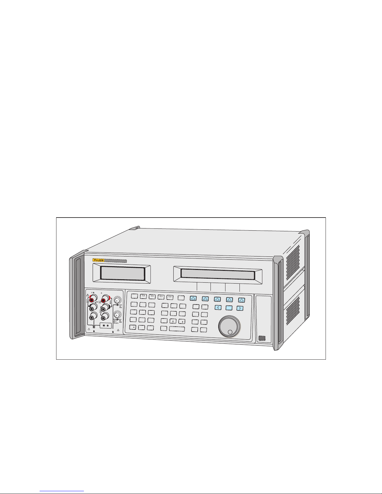
The 5522A Calibrator (hereafter “the Product”, or “the Calibrator”), shown in Figure 1-1
is a fully programmable precision source of the following:
• DC voltage from 0 V to ±1020 V.
• AC voltage from 1 mV to 1020 V, with output from 10 Hz to 500 kHz.
• AC current from 29 μA to 20.5 A, with variable frequency limits.
• DC current from 0 to ±20.5 A.
• Resistance values from a short circuit to 1100 MΩ.
• Capacitance values from 220 pF to 110 mF.
• Simulated output for eight types of Resistance Temperature Detectors (RTDs).
• Simulated output for eleven types of thermocouples.
Warning
5522A
CALIBRATOR
NORMAL AUX
V, , ,
RTD
20V PK MAX
GUARD
A, -SENSE,
HI
LO
SCOPE
AUX V
OUT
TRIG
20A
20V PK MAX
TC
OPRSTBY EARTH
7 8 9
4 5 6
123
+
/
0
•
EXGRD
PREV
SCOPE
MENU
dBm sec
m
V Hz
n
W
k
A
p
M
SHIFT
ENTER
SETUP
¡F
¡C
F
RESET
NEW
CE
REF
MEAS
MORE
TC
MODES
MULT
DIV
x
EDIT
FIELD
POWER
gjh001.eps
Figure 1-1. 5522A Multi-Product Calibrator
Features of the Calibrator include the following:
• Automatic meter error calculation, with user selectable reference values.
• X and D keys that change the output value to pre-determined cardinal values
for various functions.
• Programmable entry limits that prevent the operator from entering values that exceed
preset output limits.
• Simultaneous output of voltage and current, up to an equivalent of 20.9 kW.
• Pressure measurement when used with Fluke 700 Series pressure modules.
1-3
Page 24

5522A
Operators Manual
Safety Information
• 10 MHz reference input and output. Use this to input a high-accuracy 10 MHz
reference to transfer the frequency accuracy to the 5522A, or to synchronize one or
more additional Calibrators to a master 5522A.
• Simultaneous output of two voltages.
• Extended bandwidth mode outputs multiple waveforms down to 0.01 Hz, and sine
waves to 2 MHz.
• Variable phase signal output.
• Standard IEEE-488 (GPIB) interface, complying with ANSI/IEEE Standards
488.1-1987 and 488.2-1987.
• EIA Standard RS-232 serial data interface for printing, displaying, or transferring
internally stored calibration constants, and for remote control of the 5522A.
• Pass-through RS-232 serial data interface for communicating with the Unit Under
Test (UUT).
This Calibrator complies with:
• ANSI/ISA-61010-1 (82.02.01)
• CAN/CSA C22.2 No. 61010-1-04
• ANSI/UL 61010-1:2004
• EN 61010-1:2001
In this manual, a Warning identifies conditions and actions that pose hazards to the user.
A Caution identifies conditions and actions that may damage the Calibrator or the
equipment under test.
Symbols used in this manual and on the Product are explained in Table 1.
Table 1-1. Symbols
Symbol Description Symbol Description
CAT I
IEC Measurement Category I – CAT I
is for measurements not directly
connected to mains. Maximum
transient Overvoltage is as specified
by terminal markings.
Conforms to European Union
directives
Risk of Danger. Important information.
See manual.
Earth ground
Conforms to relevant North American
Safety Standards.
Do not dispose of this product as unsorted
municipal waste. Go to Fluke’s website for
recycling information.
Hazardous voltage
Conforms to relevant Australian EMC
requirements
Warning
To prevent personal injury:
• Use the Product only as specified, or the protection
supplied by the Product can be compromised.
To prevent possible electrical shock, fire, or personal injury:
1-4
Page 25

Introduction and Specifications
Overload Protection 1
• Read all safety Information before you use the Product.
• Do not use the Product if it operates incorrectly.
• Replace the mains power cord if the insulation is damaged
or if the insulation shows signs of wear.
• Do not touch voltages > 30 V ac rms, 42 V ac peak, or 60 V
dc.
• Do not use the Product around explosive gas, vapor, or in
damp or wet environments.
• Make sure the ground conductor in the mains power cord is
connected to a protective earth ground. Disruption of the
protective earth could put voltage on the chassis that could
cause death.
• Use only the mains power cord and connector approved for
the voltage and plug configuration in your country and rated
for the Product.
• Use only cables with correct voltage ratings.
Overload Protection
The Calibrator supplies reverse-power protection, fast output disconnection, and/or fuse
protection on the output terminals for all functions.
Reverse-power protection prevents damage to the calibrator from occasional, accidental,
normal-mode, and common-mode overloads to a maximum of ±300 V peak. It is not
intended as protection against frequent (systematic and repeated) abuse. Such abuse will
cause the Calibrator to fail.
For volts, ohms, capacitance, and thermocouple functions, there is fast output
disconnection protection. This protection senses applied voltages higher than 20 volts on
the output terminals. It quickly disconnects the internal circuits from the output terminals
and resets the calibrator when such overloads occur.
For current and aux voltage functions, user replaceable fuses supply protection from
overloads applied to the Current/Aux Voltage output terminals. The fuses are accessed by
an access door on the bottom of the calibrator. You must use replacement fuses of the
same capacity and type specified in this manual, or the protection supplied by the
Calibrator will be compromised.
Operation Overview
The Calibrator may be operated at the front panel in the local mode, or remotely using
RS-232 or IEEE-488 ports. For remote operations, several software options are available
to integrate 5522A operation into a wide variety of calibration requirements.
Local Operation
Typical local operations include front panel connections to the Unit Under Test (UUT),
and then manual keystroke entries at the front panel to place the Calibrator in the desired
output mode. The front panel layout facilitates hand movements from left to right, and
multiply and divide keys make it easy to step up or down at the press of a single key. You
can also review Calibrator specifications at the push of two buttons. The backlit liquid
crystal display is easy to read from many different viewing angles and lighting
conditions, and the large, easy-to-read keys are color-coded and provide tactile feedback.
1-5
Page 26
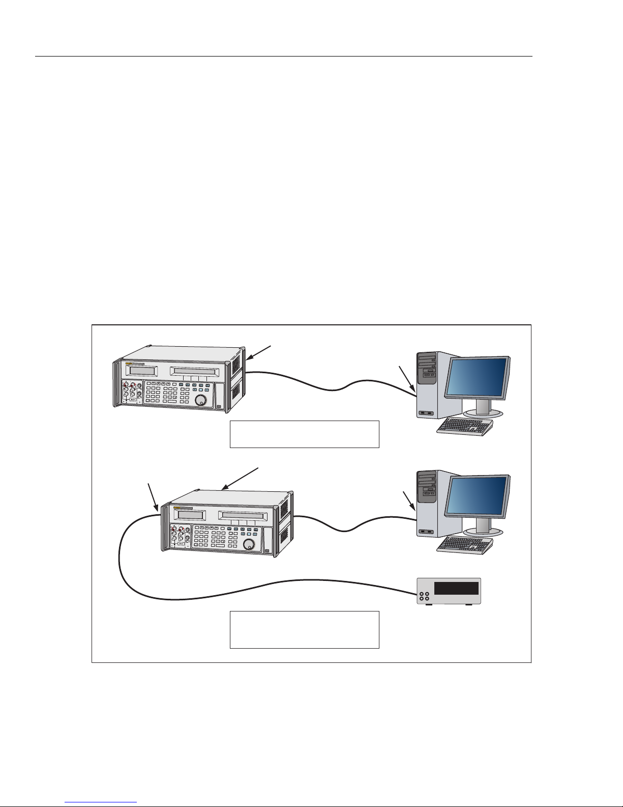
5522A
Operators Manual
Remote Operation (RS-232)
There are two rear-panel serial data RS-232 ports: SERIAL 1 FROM HOST, and
SERIAL 2 TO UUT (see Figure 1-2). Each port is dedicated to serial data
communications for operating and controlling the 5522A during calibration procedures.
For complete information on remote operations, see Chapter 5.
The SERIAL 1 FROM HOST serial data port connects a host terminal or personal
computer to the Calibrator. You have several choices for sending commands to the
Calibrator: you can enter commands from a terminal (or a PC running a terminal
program), you can write your own programs using BASIC, or you can run optional
Windows-based software such as 5500/CAL or MET/CAL. The 5500/CAL Software
includes more than 200 example procedures covering a wide range of test tools the
5522A can calibrate. (See Chapter 6 for a discussion of the RS-232 commands.)
The SERIAL 2 TO UUT serial data port connects a UUT to a PC or terminal via the
5522A (see Figure 1-2). This “pass-through” configuration eliminates the requirement for
two COM ports at the PC or terminal. A set of four commands control the operation of
the SERIAL 2 TO UUT serial port. See Chapter 6 for a discussion of the UUT_*
commands. The SERIAL 2 TO UUT port is also used to connect to the Fluke 700 Series
Pressure Modules.
5522A
CALIBRATOR
NORMAL
AUX
SCOPE
V, , ,
RTD
A, -SENSE,
AUX V
OUT
OPRSTBY EARTH
HI
LO
GUARD
20V PK MAX
EXGRD
7
8 9
TRIG
456
20A
123
+
/
0 •
20V PK MAX
TC
5522A
SERIAL 2
TO UUT port
SERIAL 1 FROM HOST port
COM port
PREV
SCOPE
MENU
dBm
sec
m
V
SETUP
Hz
RESET
EDIT
n
W
k
p
M
SHIFT
FIELD
¡F
NEW
A
¡C
CE
REF
MEAS
MORE
F
TC
MODES
MULT
ENTER
DIV
x
POWER
RS-232 Remote Operation using the
SERIAL 1 FROM HOST port
PC or Terminal
SERIAL 1 FROM HOST port
COM port
5522A
5522A
CALIBRATOR
CALIBRATOR
NORMAL
AUX
SCOPE
V,
, ,
RTD
A, -SENSE,
AUX V
OUT
HI
LO
TRIG
GUARD
20A
20V PK MAX
20V PK MAX
TC
+
7
4 5 6
1 2 3
/
OPRSTBY
EARTH SCOPE
8 9
0
•
PREV
EXGRD
MENU
dBm sec
m
V Hz
SETUP
RESET
EDIT
n
W
k
p
M
SHIFT
FIELD
¡F
NEW
A
¡C
CE
REF
MEAS
MORE
F
TC
MODES
MULT
ENTER
DIV
x
POWER
5522A
RS-232 Remote Operation using the
PC or Terminal
Unit Under Test
SERIAL 1 FROM HOST and
SERIAL 2 TO UUT ports
Remote Operation (IEEE-488)
The rear panel IEEE-488 port is a fully programmable parallel interface bus meeting
standard IEEE-488.1 and supplemental standard IEEE-488.2. Under the remote control of
an instrument controller, the Calibrator operates exclusively as a “talker/listener.” You
1-6
Figure 1-2. RS-232 Remote Connection
gjh002.eps
Page 27

Introduction and Specifications
Where to Go from Here 1
can write your own programs using the IEEE-488 command set or run the optional
Windows-based MET/CAL software. (See Chapter 6 for a discussion of the commands
available for IEEE-488 operation.)
Where to Go from Here
To locate specific information concerning the installation and operation of the 5522A
calibrator, refer to the following list:
• Unpacking and setup: Chapter 2, “Preparing for Operation”
• Installation and rack mounting: Chapter 2, “Preparing for Operation,” and the rack
mount kit instruction sheet
• AC line power and interface cabling: Chapter 2, “Preparing for Operation”
• Controls, indicators, and displays: Chapter 3, “Features”
• Front panel operation: Chapter 4, “Front Panel Operation”
• Cabling to a UUT (Unit Under Test): Chapter 4, “Front Panel Operation”
• Remote operation (IEEE-488 or serial): Chapter 5, “Remote Operation”
• Calibrating an Oscilloscope: Chapter 8, “Oscilloscope Calibration Options”
• Accessories to the 5522A Calibrator: Chapter 9, “Accessories”
• Performance Specifications: Chapter 1, “Introduction and Specifications”
Instruction Manuals
The 5522A Manual Set provides complete information for operators. The set includes:
• 5522A Operators Manual on included CD-ROM (PN 3795084)
• 5522A Getting Started Manual (PN 3795091)
One of each manual listed above is shipped with the instrument. Order additional copies
of the manuals separately using the part number provided. For ordering instructions, refer
to the Fluke Catalog, or ask a Fluke sales representative (see “Service Information” in
Chapter 2).
5522A Getting Started Manual
This 5522A Getting Started Manual contains a brief introduction to the 5522A Manual
Set, instructions on how to get your calibrator prepared for operation and a complete set
of specifications.
5522A Operators Manual
This 5522A Operators Manual provides complete information for installing the 5522A
Calibrator and operating it from the front panel keys and in remote configurations. This
manual also provides a glossary of calibration, specifications, and error code information.
The Operators Manual includes the following topics:
• Installation
• Operating controls and features, including front panel operation
• Remote operation (IEEE-488 bus or serial port remote control)
• Serial port operation (printing, displaying, or transferring data, and setting up for
serial port remote control)
• Operator maintenance, including verification procedures and calibration approach for
the 5522A
• Oscilloscope calibration options
• Accessories
1-7
Page 28

5522A
Operators Manual
General Specifications
The following tables list the 5522A specifications. All specifications are valid after allowing a warm-up period of 30
minutes, or twice the time the 5522A has been turned off. (For example, if the 5522A has been turned off for 5 minutes,
the warm-up period is 10 minutes.)
All specifications apply for the temperature and time period indicated. For temperatures outside of tcal ±5 °C (tcal is the
ambient temperature when the 5522A was calibrated), the temperature coefficient as stated in the General Specifications
must be applied.
The specifications also assume the Calibrator is zeroed every seven days or whenever the ambient temperature changes
more than 5 °C. The tightest ohms specifications are maintained with a zero cal every 12 hours within ±1 °C of use.
Also see additional specifications later in this chapter for information on extended specifications for ac voltage and
current.
Warmup Time ........................................................ Twice the time since last warmed up, to a maximum of 30 minutes.
Settling Time ......................................................... Less than 5 seconds for all functions and ranges except as noted.
Standard Interfaces .............................................. IEEE-488 (GPIB), RS-232
Temperature
Operating ............................................................ 0 °C to 50 °C
Calibration (tcal).................................................. 15 °C to 35 °C
Storage ............................................................... -20 ° to +50 °C; The DC current ranges 0 to 1.09999 A and 1.1 A to
Temperature Coefficient....................................... Temperature coefficient for temperatures outside tcal +5 °C is 0.1/X/°C
Relative Humidity
Operating ............................................................ <80 % to 30 °C, <70 % to 40 °C, <40 % to 50 °C
Storage ............................................................... <95 %, non-condensing. After long periods of storage at high humidity,
Altitude
Operating ............................................................ 3,050 m (10,000 ft) maximum
Non-operating ..................................................... 12,200 m (40,000 ft) maximum
Safety ..................................................................... Complies with EN/IEC 61010-1:2001, CAN/CSA-C22.2 No.
Output Terminal Electrical Overload Protection Provides reverse-power protection, immediate output disconnection,
Analog Low Isolation............................................ 20 V normal operation, 400 V peak transient
EMC ........................................................................
Line Power............................................................. Line Voltage (selectable): 100 V, 120 V, 220 V, 240 V
Power Consumption ............................................. 600 VA
Dimensions (HxWxL) .............................................. 17.8 cm x 43.2 cm x 47.3 cm (7 in x 17 in x 18,6 in) Standard rack
Weight (without options) .........................................22 kg (49 lb)
Absolute Uncertainty Definition ..........................The 5522A specifications include stability, temperature coefficient,
Specification Confidence Interval .......................99 %
1-8
2.99999 A are sensitive to storage temperatures above 50 °C. If the
5522A is stored above 50 °C for greater than 30 minutes, these ranges
must be re-calibrated. Otherwise, the 90 day and 1 year uncertainties
of these ranges double.
of the 90-day specification (or 1-year, as applicable) per °C
a drying-out period (with power on) of at least one week may be
required.
61010-1-04, ANSI/UL 61010-1:2004;
and/or fuse protection on the output terminals for all functions. This
protection is for applied external voltages up to ±300 V peak.
Complies with EN/IEC 61326-1:2006. If used in areas with
Electromagnetic fields of 1 to 3 V/m, resistance outputs have a floor
adder of 0.508 Ω. Performance not specified above 3 V/m. This
instrument may be susceptible to electro-static discharge (ESD) from
direct contact to the binding posts. Good static aware practices should
be followed when handling this and other pieces of electronic
equipment.
Line Frequency: 47 Hz to 63 Hz
Line Voltage Variation: ±10 % about line voltage setting
For optimal performance at full dual outputs (e.g. 1000 V, 20 A) choose
a ling voltage setting that is ±7.5 % from nominal.
width and rack increment, plus 1.5 cm (0.6 in) for feet on bottom of
unit.
linearity, line and load regulation, and the traceability of the external
standards used for calibration. You do not need to add anything to
determine the total specification of the 5522A for the temperature
range indicated.
Page 29

Introduction and Specifications
Detailed Specifications 1
Detailed Specifications
DC Voltage
Absolute Uncertainty, tcal ±5 °C
Range
0 to 329.9999 mV
±(ppm of output +μV)
90 days 1 year
15 + 1 20 + 1 3 + 1
0 to 3.299999 V 9 + 2 11 + 2 2 + 1.5 1 10 mA
0 to 32.99999 V 10 + 20 12 + 20 2 + 15 10 10 mA
30 V to 329.9999 V 15 + 150 18 + 150 2.5 + 100 100 5 mA
100 V to 1020.000 V 15 + 1500 18 + 1500 3 + 300 1000 5 mA
Auxiliary Output (dual output mode only)
0 to 329.9999 mV 300 + 350 400 + 350 30 + 100 1 5 mA
0.33 to 3.299999 V 300 + 350 400 + 350 30 + 100 10 5 mA
3.3 to 7 V 300 + 350 400 + 350 30 + 100 100 5 mA
TC Simulate and Measure in Linear 10 μV/°C and 1 mV/°C modes
0 to 329.9999 mV 40 + 3 50 + 3 5 + 2 0.1
[1] Remote sensing is not provided. Output resistance is <5 mΩ for outputs ≥0.33 V. The AUX output has an output resistance of
<1 Ω. TC simulation has an output impedance of 10 Ω ±1 Ω.
[2] Two channels of dc voltage output are provided.
[3] TC simulating and measuring are not specified for operation in electromagnetic fields above 0.4 v/m.
Range
0 to 329.9999 mV
0 to 3.299999 V
0 to 32.99999 V
30 V to 329.9999 V 10 + 1 mV 20 mV
100 V to 1020.000 V 10 + 5 mV 20 mV
0 to 329.9999 mV
0.33 to 3.299999 V
3.3 to 7 V
[1] Two channels of dc voltage output are provided.
Bandwidth 0.1 Hz to 10 Hz p-p ±(ppm
output + floor)
0 + 1 μV 6 μV
0 + 10 μV 60 μV
0 + 100 μV 600 μV
Auxiliary Output (dual output mode only)
0 + 5 μV 20 μV
0 + 20 μV 200 μV
0 + 100 μV 1000 μV
Stability
24 hours, ±1 °C
±(ppm, output +μV)
Noise
Resolution μV
0.1
[2]
[3]
Max Burden
65 Ω
10 Ω
Bandwidth 10 Hz to 10 kHz rms
[1]
[1]
DC Current
Absolute Uncertainty, tcal ±5 °C
Range
0 to 329.999 μA
0 to 3.29999 mA
0 to 32.9999 mA
0 to 329.999 mA
0 to 1.09999 A
1.1 A to 2.99999 A 300 + 40 380 + 40
0 to 10.9999 A
(20 A Range)
11 to 20.5 A
[1] Duty Cycle: Currents <11 A may be provided continuously. For currents >11 A, see Figure 1-4. The current may be provided 60-
[2] Floor specification is 1500 μA within 30 seconds of selecting operate. For operating times >30 seconds, the floor specification is
[1]
800 + 750
T-I minutes any 60 minute period where T is the temperature in °C (room temperature is about 23 °C) and I is the output current
in amperes. For example, 17 A, at 23 °C could be provided for 60-17-23 = 20 minutes each hour. When the 5520A is outputting
currents between 5 and 11 amps for long periods, the internal self-heating reduces the duty cycle. Under those conditions, the
allowable "on" time indicated by the formula and Figure B is achieved only after the 5520A is outputting currents <5 A for the "off"
period first.
750 μA.
±(ppm of output +μA)
90 days 1 year
120 + 0.02 150 + 0.02 1 nA
80 + 0.05 100 + 0.05
80 + 0.25 100 + 0.25
80 + 2.5 100 + 2.5
160 + 40 200 + 40
380 + 500 500 + 500
[2]
1000 + 750
Resolution
Max Compliance
Voltage V
Max Inductive
Load mH
10
0.01 μA
0.1 μA
1 μA
10 μA
10 μA
100 μA
[2]
100 μA
10
7
7
6
6
4
4
400
1-9
Page 30
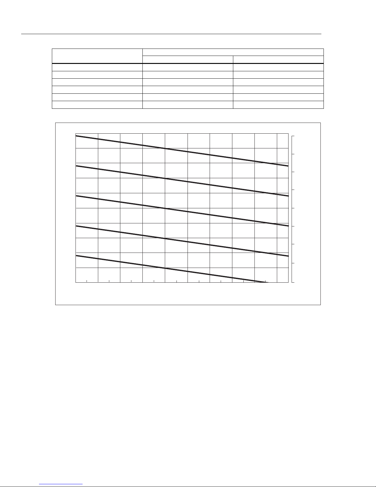
5522A
Operators Manual
Range
0 to 329.999 μA
0 to 3.29999 mA 20 nA 200 nV
0 to 32.9999 mA 200 nA
0 to 329.999 mA 2000 nA
0 to 2.99999 A
0 to 20.5 A
Bandwidth 0.1 Hz to 10 Hz p-p Bandwidth 10 Hz to 10 kHz rms
2 nA 20 nV
20 μA
200 μA
Noise
2.0 μA
20 μA
1 mA
10 mA
50
45
40
35
10 C
30
25
Minutes per Hour
20
15
30 C
20 C
10
40 C
5
Ambient
0 C
80%
70%
60%
50%
40%
Duty Cycle (%)
30%
20%
10%
0
11 12 13 14 15 16 17 18 19 20
Current (Amps)
Figure 1-3. Allowable Duration of Current >11 A A
0%
nn326f.eps
1-10
Page 31
Introduction and Specifications
Detailed Specifications 1
Resistance
Absolute Uncertainty, tcal ±5 °C ±(ppm of output +floor)
[1]
Range
0 to
10.9999 Ω
11 to
32.9999 Ω
33 to
109.9999 Ω
110 Ω to
329.9999 Ω
330 Ω to
1.099999 kΩ
1.1 to
3.299999 kΩ
3.3 to
10.99999 kΩ
11 to
32.99999 kΩ
33 to
109.9999 kΩ
110 to
329.99999 kΩ
330 kΩ to
1.099999 MΩ
1.1 to
3.299999 MΩ
3.3 to
10.99999 MΩ
11 to
32.99999 MΩ
33 to
109.9999 MΩ
110 to
329.9999 MΩ
330 to
1100 MΩ
[1] Continuously variable from 0 Ω to 1.1 G Ω.
[2] Applies for 4-WIRE compensation only. For 2-WIRE and 2-WIRE COMP, add 5 μV per Amp of stimulus current to the floor
[3] For currents lower than shown, the floor adder increases by Floor(new) = Floor(old) x Imin/Iactual. For example, a 50 μA stimulus
ppm of output
90 days 1 year
Temp and temp since ohms zero cal
12 hrs ±1 °C 7 days ±5 °C
35 40 0.001 0. 01 0.0001 1 mA to 125 mA
25 30 0.0015 0.015 0.0001 1 mA to 125 mA
22 28 0.0014 0.015 0.0001 1 mA to 70 mA
22 28 0.002 0.02 0.0001 1 mA to 40 mA
22 28 0.002 0.02 0.001 1 mA to 18 mA
22 28 0.02 0.2 0.001
22 28 0.02 0.1 0.01
22 28 0.2 1 0.01
22 28 0.2 1 0. 1
25 32 2 10 0.1
25 32 2 10 1
40 60 30 150 1
110 130 50 250 10
200 250 2500 2500 10 25 nA to 500 nA
400 500 3000 3000 100 25 nA to 180 nA
2500 3000 100000 100000 1000 2.5 nA to 50 nA
12000 15000 500000 500000 10000 1 nA to 13 nA
specification. For example, in 2-WIRE mode, at 1 kΩ the floor specification within 12 hours of an ohms zero cal for a measurement
current of 1 mA is:
0.002 Ω 5 μV / 1 mA = (0.022 + 0.005) Ω = 0.007 Ω.
measuring 100 Ω has a floor specification of: 0.0014 Ω x 1 mA/50 μA = 0.028 Ω assuming an ohms zero calibration within
12 hours.
Floor (Ω)
[2]
Resolution
Ω
Allowable Current
100 μA to 5 mA
100 μA to 1.8 mA
10 μA to 0.5 mA
10 μA to 0.18 mA
1 μA to 0.05 mA
1 μA to 0.018 mA
250 nA to 5 μA
250 nA to 1.8 μA
[3]
1-11
Page 32
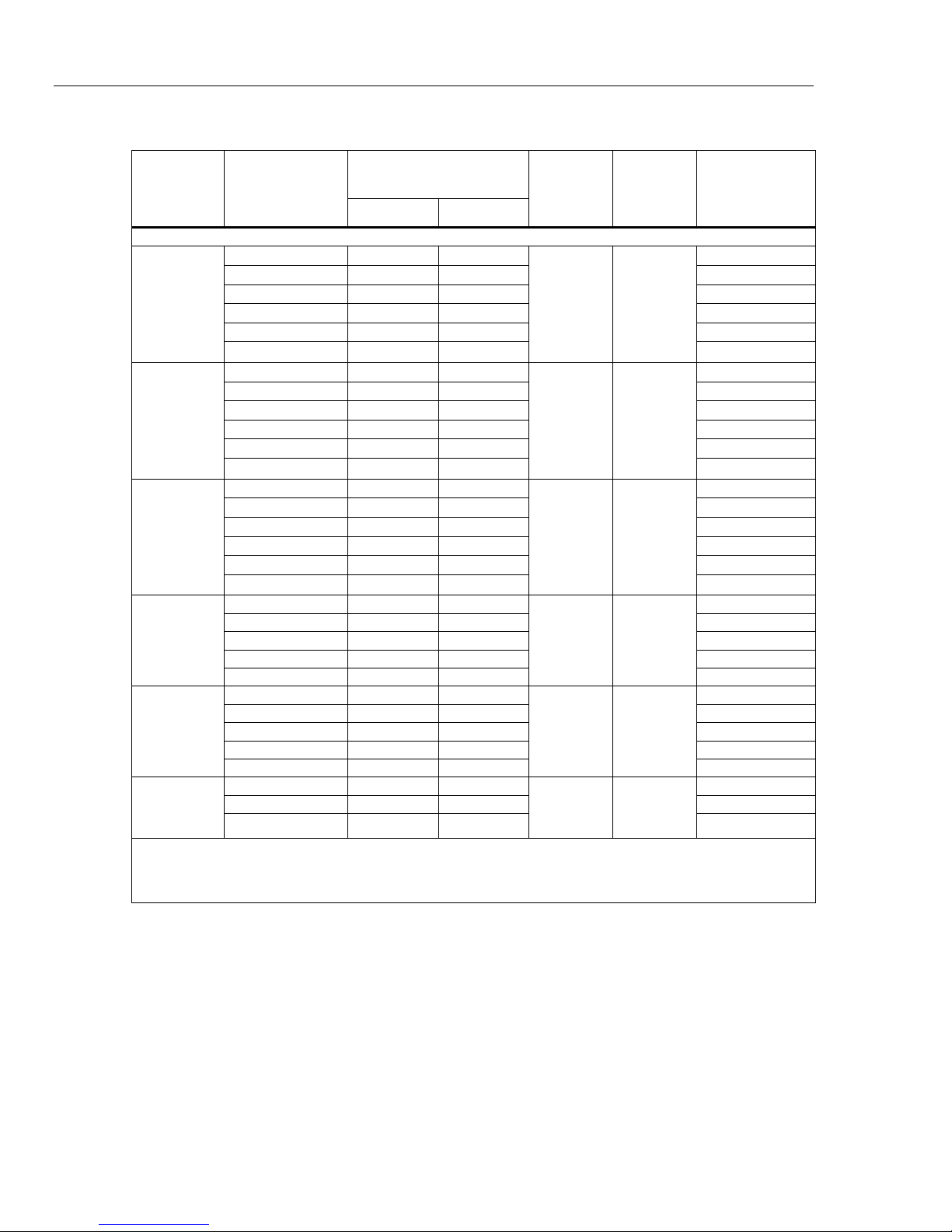
5522A
Operators Manual
AC Voltage (Sine Wave)
Range Frequency
1.0 mV to
32.999 mV
33 mV to
329.999 mV
0.33 V to
3.29999 V
3.3 V to
32.9999 V
33 V to
329.999 V
330 V to
1020 V
[1] Max Distortion for 100 kHz to 200 kHz. For 200 kHz to 500 kHz, the maximum distortion is 0.9 % of output + floor as shown.
Note
Remote sensing is not provided. Output resistance is <5 mΩ for outputs ≥0.33 V. The AUX output resistance is <1 Ω. The maximum
load capacitance is 500 pF, subject to the maximum burden current limits
Absolute Uncertainty,
tcal ±5 °C
±(ppm of output + μV)
90 days 1 year
Normal Output
10 Hz to 45 Hz 600 + 6 800 + 6
45 Hz to 10 kHz 120 + 6 150 + 6
10 kHz to 20 kHz 160 + 6 200 + 6
20 kHz to 50 kHz 800 + 6 1000 + 6
50 kHz to 100 kHz 3000 + 12 3500 + 12
100 kHz to 500 kHz 6000 + 50 8000 + 50
10 Hz to 45 Hz 250 + 8 300 + 8
45 Hz to 10 kHz 140 + 8 145 + 8
10 kHz to 20 kHz 150 + 8 160 + 8
20 kHz to 50 kHz 300 + 8 350 + 8
50 kHz to 100 kHz 600 + 32 800 + 32
100 kHz to 500 kHz 1600 + 70 2000 + 70
10 Hz to 45 Hz 250 + 50 300 + 50
45 Hz to 10 kHz 140 + 60 150 + 60
10 kHz to 20 kHz 160 + 60 190 + 60
20 kHz to 50 kHz 250 + 50 300 + 50
50 kHz to 100 kHz 550 + 125 700 + 125
100 kHz to 500 kHz 2000 + 600 2400 + 600
10 Hz to 45 Hz 250 + 650 300 + 650 0.15 + 2 mV
45 Hz to 10 kHz 125 + 600 150 + 600 0.035 + 2 mV
10 kHz to 20 kHz 220 + 600 240 + 600 0.08 + 2 mV
20 kHz to 50 kHz 300 + 600 350 + 600 0.2 + 2 mV
50 kHz to 100 kHz 750 + 1600 900 + 1600
45 Hz to 1 kHz 150 + 2000 190 + 2000 0.15 + 10 mV
1 kHz to 10 kHz 160 + 6000 200 + 6000 0.05 +10 mV
10 kHz to 20 kHz 220 + 6000 250 + 6000 0.6 + 10 mV
20 kHz to 50 kHz 240 + 6000 300 + 6000 0.8 + 10 mV
50 kHz to 100 kHz 1600 + 50000 2000 + 50000
45 Hz to 1 kHz 250 + 10000 300 + 10000 0.15 + 30 mV
1 kHz to 5 kHz 200 + 10000 250 + 10000 0.07 + 30 mV
5 kHz to 10 kHz 250 + 10000 300 + 10000
Resolution
1 μV 65 Ω
1 μV 65 Ω
10 μV
100 μV
1 mV
10 mV
Max
Burden
10 mA
10 mA
5 mA,
except
20 mA for
45 Hz to
65 Hz
2 mA,
except 6 mA
for 45 Hz to
65 Hz
Max Distortion and
Noise
10 Hz to 5 MHz
Bandwidth
±(% output + floor)
0.15 + 90 μV
0.035 + 90 μV
0.06 + 90 μV
0.15 + 90 μV
0.25 + 90 μV
0.3 + 90 μV
0.15 + 90 μV
0.035 + 90 μV
0.06 + 90 μV
0.15 + 90 μV
0.20 + 90 μV
0.20 + 90 μV
0.15 + 200 μV
0.035 + 200 μV
0.06 + 200 μV
0.15 + 200 μV
0.20 + 200 μV
0.20 + 200 μV
0.5 + 2 mV
1.0 + 10 mV
0.07 + 30 mV
[1]
[1]
[1]
1-12
Page 33
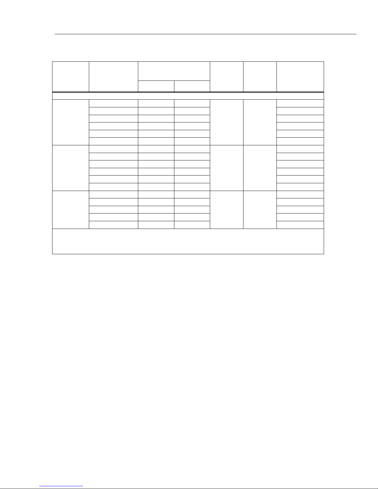
Introduction and Specifications
Detailed Specifications 1
AC Voltage (Sine Wave) (cont.)
Absolute Uncertainty,
Range
10 mV to
329.999 mV
0.33 V to
3.29999 V
3.3 v to 5 v
Note
Remote sensing is not provided. Output resistance is <5 mΩ for outputs ≥0.33 V. The AUX output resistance is <1 Ω. The maximum
load capacitance is 500 pF, subject to the maximum burden current limits
[1] There are two channels of voltage output. The maximum frequency of the dual output is 30 kHz.
Frequency
10 Hz to 20 Hz 0.15 + 370 0.2 + 370
20 Hz to 45 Hz 0.08 + 370 0.1 + 370
45 Hz to 1 kHz 0.08 + 370 0.1 + 370
1 kHz to 5 kHz 0.15 + 450 0.2 + 450
5 kHz to 10 kHz 0.3 + 450 0.4 + 450
10 kHz to 30 kHz 4.0 + 900 5.0 + 900
10 Hz to 20 Hz 0.15 + 450 0.2 + 450
20 Hz to 45 Hz 0.08 + 450 0.1 + 450
45 Hz to 1 kHz 0.07 + 450 0.09 + 450
1 kHz to 5 kHz 0.15 + 1400 0.2 + 1400
5 kHz to 10 kHz 0.3 + 1400 0.4 + 1400
10 kHz to 30 kHz 4.0 + 2800 5.0 + 2800
10 Hz to 20 Hz 0.15 + 450 0.2 + 450
20 Hz to 45 Hz 0.08 + 450 0.1 + 450
45 Hz to 1 kHz 0.07 + 450 0.09 + 450
1 kHz to 5 kHz 0.15 + 1400 0.2 + 1400
5 kHz to 10 kHz 0.3 + 1400 0.4 + 1400
[1]
tcal ±5 °C
±(% of output + μV)
90 days 1 year
AUX Output
Resolution
1 μv
10 μv
100 μv
Max
Burden
5 mA
5 mA
5 mA
Max Distortion and
Noise
10 Hz to 5 MHz
Bandwidth
±(% output + floor)
0.2 + 200 μV
0.06 + 200 μV
0.08 + 200 μV
0.3 + 200 μV
0.6 + 200 μV
1 + 200 μV
0.2 + 200 μV
0.06 + 200 μV
0.08 + 200 μV
0.3 + 200 μV
0.6 + 200 μV
1 + 200 μV
0.2 + 200 μV
0.06 + 200 μV
0.08 + 200 μV
0.3 + +200 μV
0.6 + 200 μV
1-13
Page 34
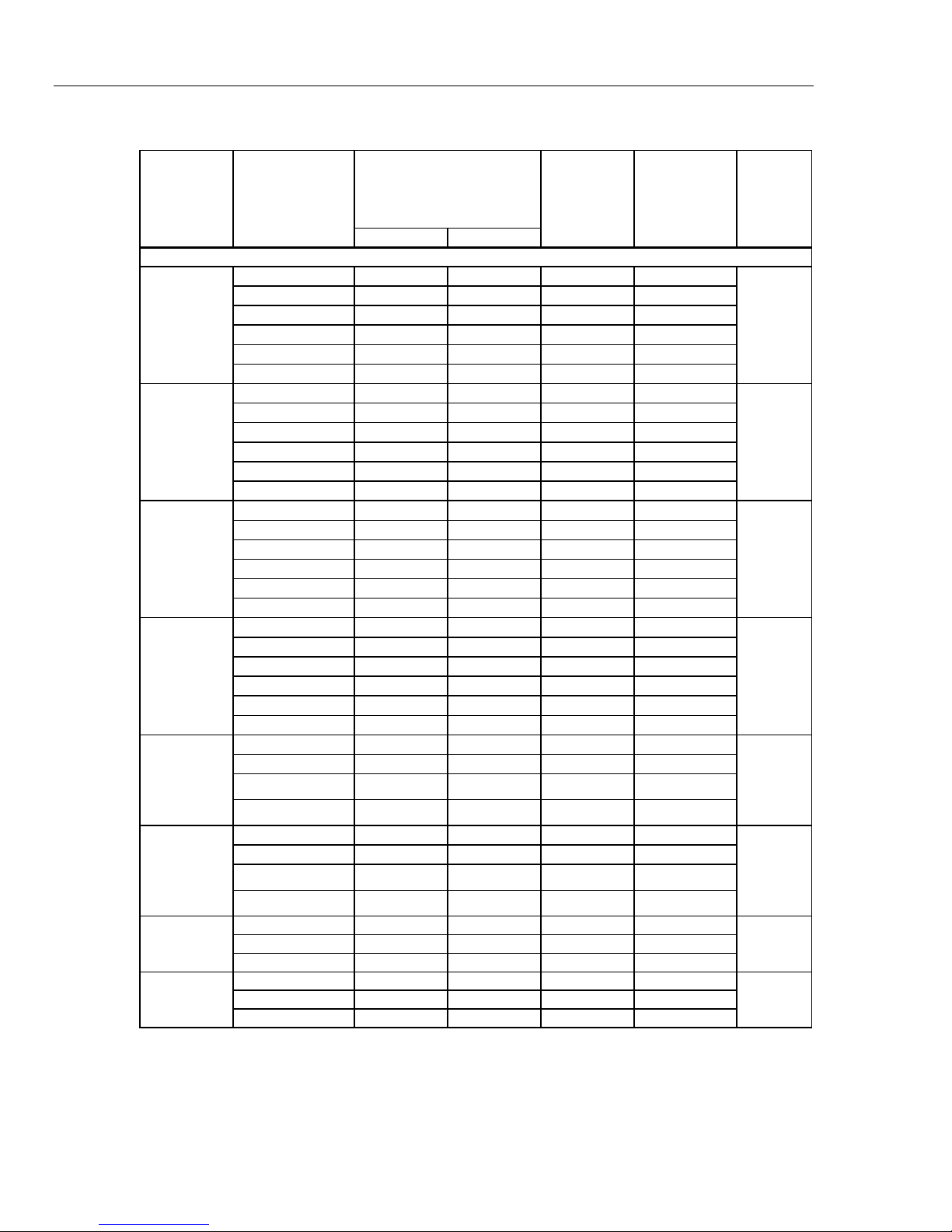
5522A
Operators Manual
AC Current (Sine Wave)
Range Frequency
10 to 20 Hz 0.16 + 0.1 0.2 + 0.1 0.05
20 to 45 Hz 0.12 + 0.1 0.15 + 0.1 0.05
29.00 to
329.99 μA
0.33 to
3.29999 mA
3.3 to
32.9999 mA
33 to
329.999 mA
0.33 to
1.09999 A
1.1 to
2.99999 A
3 to
10.9999 A
11 to
[1]
20.5 A
45 Hz to 1 kHz 0.1 + 0.1 0.125 + 0.1 0.05
1 to 5 kHz 0.25 + 0.15 0.3 + 0.15 1.5
5 to 10 kHz 0.6 + 0.2 0.8 + 0.2 1.5
10 to 30 kHz 1.2 + 0.4 1.6 + 0.4 10
10 to 20 Hz 0.16 + 0.15 0.2 + 0.15 0.05
20 to 45 Hz 0.1 + 0.15 0.125 + 0.15 0.05
45 Hz to 1 kHz 0.08 + 0.15 0.1 + 0.15 0.05
1 to 5 kHz 0.16 + 0.2 0.2 + 0.2 1.5
5 to 10 kHz 0.4 + 0.3 0.5 + 0.3 1.5
10 to 30 kHz 0.8 + 0.6 1.0 + 0.6 10
10 to 20 Hz 0.15 + 2 0.18 + 2 0.05
20 to 45 Hz 0.075 + 2 0.09 + 2 0.05
45 Hz to 1 kHz 0.035 + 2 0.04 + 2 0.05
1 to 5 kHz 0.065 + 2 0.08 + 2 1.5
5 to 10 kHz 0.16 + 3 0.2 + 3 1.5
10 to 30 kHz 0.32 + 4 0.4 + 4 10
10 to 20 Hz 0.15 + 20 0.18 + 20 0.05
20 to 45 Hz 0.075 + 20 0.09 + 20 0.05
45 Hz to 1 kHz 0.035 + 20 0.04 + 20 0.05
1 to 5 kHz 0.08 + 50 0.10 + 50 1.5
5 to 10 kHz 0.16 + 100 0.2 + 100 1.5
10 to 30 kHz 0.32 + 200 0.4 + 200 10
10 to 45 Hz 0.15 + 100 0.18 + 100
45 Hz to 1 kHz 0.036 + 100 0.05 + 100
1 to 5 kHz 0.5 + 1000 0.6 + 1000
5 to 10 kHz 2.0 + 5000 2.5 + 5000
10 to 45 Hz 0.15 + 100 0.18 + 100
45 Hz to 1 kHz 0.05 + 100 0.06 + 100
1 to 5 kHz 0.5 + 1000 0.6 + 1000
5 to 10 kHz 2.0 + 5000 2.5 + 5000
45 to 100 Hz 0.05 + 2000 0.06 + 2000 0.2 + 3 mA
100 Hz to 1 kHz 0.08 + 2000 0.10 + 2000 0.1 + 3 mA
1 to 5 kHz 2.5 + 2000 3.0 + 2000 0.8 + 3 mA
45 to 100 Hz 0.1 + 5000 0.12 + 5000 0.2 + 3 mA
100 Hz to 1 kHz 0.13 + 5000 0.15 + 5000 0.1 + 3 mA
1 to 5 kHz 2.5 + 5000 3.0 + 5000 0.8 + 3 mA
Absolute Uncertainty,
tcal ±5 °C
±(% of output + μA)
90 days 1 year
LCOMP Off
Compliance
adder ±(μA/V)
[2]
[3]
[2]
[3]
Max Distortion &
Noise 10 Hz to
100 kHz BW
±(% of output +
floor)
0.15 + 0.5 μA
0.1 + 0.5 μA
0.05 + 0.5 μA
0.5 + 0.5 μA
1.0 + 0.5 μA
1.2 + 0.5 μA
0.15 + 1.5 μA
0.06 + 1.5 μA
0.02 + 1.5 μA
0.5 + 1.5 μA
1.0 + 1.5 μA
1.2 + 0.5 μA
0.15 + 5 μA
0.05 + 5 μA
0.07 + 5 μA
0.3 + 5 μA
0.7 + 5 μA
1.0 + 0.5 μA
0.15 + 50 μA
0.05 + 50 μA
0.02 + 50 μA
0.03 + 50 μA
0.1 + 50 μA
0.6 + 50 μA
0.2 + 500 μA
0.07 + 500 μA
1 + 500 μA
2 + 500 μA
0.2 + 500 μA
0.07 + 500 μA
1 + 500 μA
2 + 500 μA
Max
Inductive
Load μH
200
200
50
50
2.5
2.5
1
1
1-14
Page 35
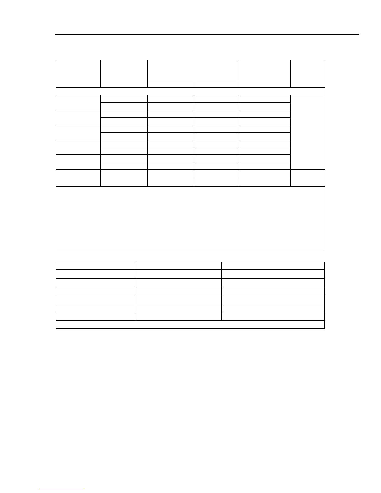
Introduction and Specifications
Detailed Specifications 1
AC Current (Sine Wave) (cont.)
Absolute Uncertainty,
Range Frequency
tcal ±5 °C
±(% of output + μA)
90 days 1 year
LCOMP On
29.00 to
329.99 μA
0.33 to
3.29999 mA
3.3 to
32.9999 mA
33 to
329.999 mA
0.33 to
2.99999 A
3 to 20.5 A
[1] Duty Cycle: Currents <11 A may be provided continuously. For currents >11 A, see Figure B. The current may be provided 60-
[2] For currents >11 A, Floor specification is 4000 μA within 30 seconds of selecting operate. For operating times >30 seconds,
[3] For currents >11 A, Floor specification is 1000 μA within 30 seconds of selecting operate. For operating times >30 seconds,
[4] Subject to compliance voltages limits.
[1]
T-I minutes any 60 minute period where T is the temperature in °C (room temperature is about 23 °C) and I is the output
current in Amps. For example, 17 A, at 23 °C could be provided for 60-17-23 = 20 minutes each hour. When the 5522A is
outputting currents between 5 and 11 amps for long periods, the internal self-heating reduces the duty cycle. Under those
conditions, the allowable "on" time indicated by the formula and Figure B is achieved only after the 5522A is outputting currents
<5 A for the "off" period first.
the floor specification is 2000 μA.
the floor specification is 5000 μA.
10 to 100 Hz 0.2 + 0.2 0.25 + 0.2 0.1 + 1.0
100 Hz to 1 kHz 0.5 + 0.5 0.6 + 0.5 0.05 + 1.0
10 to 100 Hz 0.2 + 0.3 0.25 + 0.3 0.15 + 1.5
100 Hz to 1 kHz 0.5 + 0.8 0.6 + 0.8 0.06 + 1.5
10 to 100 Hz 0.07 + 4 0.08 + 4 0.15 + 5
100 Hz to 1 kHz 0.18 + 10 0.2 + 10 0.05 + 5
10 to 100 Hz 0.07 + 40 0.08 + 40 0.15 + 50
100 Hz to 1 kHz 0.18 + 100 0.2 + 100 0.05 + 50
10 to 100 Hz 0.1 + 200 0.12 + 200 0.2 + 500
100 to 440 Hz 0.25 + 1000 0.3 + 1000 0.25 + 500
10 to 100 Hz
100 Hz to 1 kHz
0.1 + 2000
0.8 + 5000
[2]
0.12 + 2000
[3]
1.0 + 5000
Max Distortion &
Noise 10 Hz to
100 kHz BW
±(% of output + floor)
[2]
[3]
0.1 + 0
0.5 + 0
Max
Inductive
Load μH
400
[4]
400
Range
Resolution μA
Max Compliance Voltage V rms [1]
0.029 to 0.32999 mA 0.01 7
0.33 to 3.29999 mA 0.01 7
3.3 to 32.9999 mA 0.1 5
33 to 329.999 mA 1 5
0.33 to 2.99999 A 10 4
3 to 20.5 A 100 3
[1] Subject to specification adder for compliance voltages greater than 1 V rms.
1-15
Page 36
5522A
Operators Manual
Capacitance
399.9 pF
1.0999 nF
3.2999 nF
10.9999 nF
32.9999 nF
109.999 nF
329.999 nF
1.09999 μF
3.29999 μF
10.9999 μF
32.9999 μF
109.999 μF
329.999 μF
0.33 mF to
1.09999 mF
3.29999 mF
10.9999 mF
32.9999 mF
110 mF
[1] The output is continuously variable from 220 pF to 110 mF.
[2] Specifications apply to both dc charge/discharge capacitance meters and ac RCL meters. The maximum allowable peak voltage is
[3] The maximum lead resistance for no additional error in 2-wire COMP mode is 10 Ω.
Absolute Uncertainty,
tcal ±5 °C
Range
220 to
0.4 to
1.1 to
3.3 to
11 to
33 to
110 to
0.33 to
1.1 to
3.3 to
11 to
33 to
110 to
1.1 to
3.3 to
11 to
33 to
3 V. The maximum allowable peak current is 150 mA, with an rms limitation of 30 mA below 1.1 μF and 100 mA for 1.1 μF and
above.
±(% of output + floor)
90 days 1 year
0.38 + 10 pF 0.5 + 10 pF 0.1 pF 10 Hz to 10 kHz 20 kHz 40 kHz
0.38 + 0.01 nF 0.5 + 0.01 nF 0.1 pF 10 Hz to 10 kHz 30 kHz 50 kHz
0.38 + 0.01 nF 0.5 + 0.01 nF 0.1 pF 10 Hz to 3 kHz 30 kHz 50 kHz
0.19 + 0.01 nF 0.25 + 0.01 nF 0.1 pF 10 Hz to 1 kHz 20 kHz 25 kHz
0.19 + 0.01 nF 0.25 + 0.01 nF 0.1 pF 10 Hz to 1 kHz 8 kHz 10 kHz
0.19 + 0.01 nF 0.25 + 0.01 nF 1 pF 10 Hz to 1 kHz 4 kHz 6 kHz
0.19 + 0.3 nF 0.25 + 0.03 nF 1 pF 10 Hz to 1 kHz 2.5 kHz 3.5 kHz
0.19 + 1 nF 0.25 + 1 nF 10 pF 10 to 600 Hz 1.5 kHz 2 kHz
0.19 + 3 nF 0.25 + 3 nF 10 pF 10 to 300 Hz 800 Hz 1 kHz
0.19 + 10 nF 0.25 + 10 nF 100 pF 10 to 150 Hz 450 Hz 650 Hz
0.30 + 30 nF 0.40 + 30 nF 100 pF 10 to 120 Hz 250 Hz 350 Hz
0.34 + 100 nF 0.45 + 100 nF 1 nF 10 to 80 Hz 150 Hz 200 Hz
0.34 + 300 nF 0.45 + 300 nF 1 nF 0 to 50 Hz 80 Hz 120 Hz
0.34 + 1 μF 0.45 + 1 μF
0.34 + 3 μF 0.45 + 3 μF
0.34 + 10 μF 0.45 + 10 μF
0.7 + 30 μF 0.75 + 30 μF
1.0 + 100 μF 1.1 + 100 μF 10 μF
[1] [2] [3]
Resolution
10 nF 0 to 20 Hz 45 Hz 65 Hz
10 nF 0 to 6 Hz 30 Hz 40 Hz
100 nF 0 to 2 Hz 15 Hz 20 Hz
100 nF 0 to 0.6 Hz 7.5 Hz 10 Hz
Min and Max to
Meet
Specification
0 to 0.2 Hz 3 Hz 5 Hz
Allowed Frequency or
Charge-Discharge Rate
Typical Max for
<0.5 % Error
Typical Max for
<1 % Error
1-16
Page 37
Introduction and Specifications
Detailed Specifications 1
Temperature Calibration (Thermocouple)
Absolute Uncertainty
TC
Type
[1]
Range
°C
[2]
Source/Measure
tcal ±5 °C
[3]
± °C
TC
Type
[1]
Range
°C
90 days 1 year
600 to 800 0.42 0.44 -200 to -100 0.37 0.37
B
800 to 1000 0.34 0.34 -100 to 800 0.26 0.26
1000 to 1550 0.30 0.30
L
800 to 900 0.17 0.17
1550 to 1820 0.26 0.33 -200 to -100 0.30 0.40
0 to 150 0.23 0.30 -100 to -25 0.17 0.22
150 to 650 0.19 0.26 -25 to 120 0.15 0.19
C
650 to 1000 0.23 0.31 120 to 410 0.14 0.18
1000 to 1800 0.38 0.50
N
410 to 1300 0.21 0.27
1800 to 2316 0.63 0.84 0 to 250 0.48 0.57
-250 to -100 0.38 0.50 250 to 400 0.28 0.35
-100 to -25 0.12 0.16 400 to 1000 0.26 0.33
E
-25 to 350 0.10 0.14
R
1000 to 1767 0.30 0.40
350 to 650 0.12 0.16 0 to 250 0.47 0.47
650 to 1000 0.16 0.21 250 to 1000 0.30 0.36
-210 to -100 0.20 0.27 1000 to 1400 0.28 0.37
-100 to -30 0.12 0.16
J
-30 to 150 0.10 0.14 -250 to -150 0.48 0.63
150 to 760 0.13 0.17 -150 to 0 0.18 0.24
760 to 1200 0.18 0.23 0 to 120 0.12 0.16
-200 to -100 0.25 0.33
-100 to -25 0.14 0.18 -200 to 0 0.56 0.56
K
-25 to 120 0.12 0.16
S
1400 to 1767 0.34 0.46
T
120 to 400 0.10 0.14
U
0 to 600 0.27 0.27
120 to 1000 0.19 0.26
1000 to 1372 0.30 0.40
[1] Temperature standard ITS-90 or IPTS-68 is selectable.
TC simulating and measuring are not specified for operation in electromagnetic fields above 0.4 V/m.
[2] Resolution is 0.01 °C
[3] Does not include thermocouple error
[2]
Absolute Uncertainty
Source/Measure
tcal ±5 °C
[3]
± °C
90 days 1 year
1-17
Page 38
5522A
Operators Manual
Temperature Calibration (RTD)
RTD Type
Pt 385,
100 Ω
Pt 3926,
100 Ω
Pt 3916,
100 Ω
Pt 385,
200 Ω
[1] Resolution is 0.003 °C
[2] Applies for COMP OFF (to the 5522A Calibrator front panel NORMAL terminals) and 2-wire and 4-wire compensation.
[3] Based on MINCO Application Aid No. 18
Range
[1]
°C
Absolute Uncertainty
tcal ±5 °C
[2]
± °C
RTD Type
Range
[1]
°C
90 days 1 year
Absolute Uncertainty
tcal ±5 °C
[2]
± °C
90 days 1 year
-200 to -80 0.04 0.05 -200 to -80 0.03 0.04
-80 to 0 0.05 0.05 -80 to 0 0.04 0.05
0 to 100 0.07 0.07 0 to 100 0.05 0.05
100 to 300 0.08 0.09 100 to 260 0.06 0.06
300 to 400 0.09 0.10 260 to 300 0.07 0.08
Pt 385,
500 Ω
400 to 630 0.10 0.12 300 to 400 0.07 0.08
630 to 800 0.21 0.23 400 to 600 0.08 0.09
-200 to -80 0.04 0.05
600 to 630 0.09 0.11
-80 to 0 0.05 0.05 -200 to -80 0.03 0.03
0 to 100 0.07 0.07 -80 to 0 0.03 0.03
100 to 300 0.08 0.09 0 to 100 0.03 0.04
300 to 400 0.09 0.10 100 to 260 0.04 0.05
400 to 630 0.10 0.12 260 to 300 0.05 0.06
Pt 385,
1000 Ω
-200 to -190 0.25 0.25 300 to 400 0.05 0.07
-190 to -80 0.04 0.04 400 to 600 0.06 0.07
-80 to 0 0.05 0.05
0 to 100 0.06 0.06 -80 to 0 0.06 0.08
100 to 260 0.06 0.07 0 to 100 0.07 0.08
260 to 300 0.07 0.08
300 to 400 0.08 0.09
400 to 600 0.08 0.10
PtNi 385,
120 Ω
(Ni120)
Cu 427,
[3]
10 Ω
600 to 630 0.22 0.23
100 to 260 0.13 0.14
-100 to 260 0.3 0.3
600 to 630 0.21 0.23
-200 to -80 0.03 0.04
-80 to 0 0.03 0.04
0 to 100 0.04 0.04
100 to 260 0.04 0.05
260 to 300 0.11 0.12
300 to 400 0.12 0.13
400 to 600 0.12 0.14
600 to 630 0.14 0.16
DC Power Specification Summary
Voltage Range
90 days 33 mV to 1020 V 0.021
1 year 33 mV to 1020 V 0.023
[1] To determine dc power uncertainty with more precision, see the individual “AC Voltage Specifications,” “AC Current
Specifications,” and “Calculating Power Uncertainty.”
[2] Add 0.02 % unless a settling time of 30 seconds is allowed for output currents >10 A or for currents on the highest two current
ranges within 30 seconds of an output current >10 A.
1-18
Current Range
0.33 to
329.99 mA
0.33 to
2.9999 A
Absolute Uncertainty, tcal ±5 °C, ±(% of watts output)
[2]
0.06
0.019
[2]
0.07
0.022
3 to
20.5 A
[1]
[2]
[2]
Page 39
Introduction and Specifications
Detailed Specifications 1
AC Power (45 Hz to 65 Hz) Specification Summary, PF=1
Current Range
Voltage Range
3.3 to
8.999 mA
Absolute Uncertainty, tcal ±5 °C, ±(% of watts output)
90 days
1 year
Voltage Range
33 to 329.999 mV 0.13 0.09 0.13 0.09
330 mV to 1020 V 0.11 0.07 0.11 0.07
33 to 329.999 mV 0.14 0.10 0.14 0.10
330 mV to 1020 V 0.12 0.08 0.12 0.08
0.33 to
0.8999 A
Absolute Uncertainty, tcal ±5 °C, ±(% of watts output)
90 days
1 year
[1] To determine ac power uncertainty with more precision, see the individual “DC Voltage Specifications” and “DC Current
[2] Add 0.02 % unless a settling time of 30 seconds is allowed for output currents >10 A or for currents on the highest two current
33 to 329.999 mV 0.12 0.10 0.12 0.10
330 mV to 1020 V 0.10 0.08 0.11 0.09
33 to 329.999 mV 0.13 0.11 0.13 0.11
330 mV to 1020 V 0.11 0.09 0.12 0.10
Specifications” and “Calculating Power Uncertainty.”
ranges within 30 seconds of an output current >10 A.
9 to
32.999 mA
Current Range
0.9 to
2.1999 A
33 to
89.99 mA
[2]
2.2 to
4.4999 A
90 to 329.99 mA
[1]
4.5 to
20.5 A
[1]
Power and Dual Output Limit Specifications
Frequency
dc
Voltages
(NORMAL)
Currents
0 to ±1020 V 0 to ±20.5 A 0 to ±7 V
10 to 45 Hz 33 mV to 32.9999 V 3.3 mA to 2.99999 A 10 mV to 5 V 0 to 1
45 to 65 Hz 33 mV to 1020 V 3.3 mA to 20.5 A 10 mV to 5 V 0 to 1
65 to 500 Hz 330 mV to 1020 V 33 mA to 2.99999 A 100 mV to 5 V 0 to 1
65 to 500 Hz 3.3 to 1020 V 33 mA to 20.5 A 100 mV to 5 V 0 to 1
500 Hz to 1 kHz 330 mV to 1020 V 33 mA to 20.5 A 100 mV to 5 V 0 to 1
1 to 5 kHz 3.3 to 500 V 33 mA to 2.99999 A 100 mV to 5 V 0 to 1
5 to 10 kHz 3.3 to 250 V 33 to 329.99 mA 1 to 5 V 0 to 1
10 to 30 kHz 3.3 V to 250 V 33 mA to 329.99 mA 1 V to 3.29999 V 0 to 1
Notes
The range of voltages and currents shown in “DC Voltage Specifications,” “DC Current Specifications,” “AC Voltage (Sine Wave)
Specifications,” and “AC Current (Sine Wave) Specifications” are available in the power and dual output modes (except minimum
current for ac power is 0.33 mA). However, only those limits shown in this table are specified. See “Calculating Power Uncertainty” to
determine the uncertainty at these points.
The phase adjustment range for dual ac outputs is 0 ° to ±179.99 °. The phase resolution for dual ac outputs is 0.01 degree.
Voltages
(AUX)
Power Factor
(PF)
⎯
1-19
Page 40
5522A
Operators Manual
Phase
Phase (Φ)
Watts
To calculate exact ac Watts power adders due to phase uncertainty for values not shown, use the following formula:
Adder
For example: for a PF of .9205 (Φ = 23) and a phase uncertainty of
Adder
Calculating Power Uncertainty
Overall uncertainty for power output in Watts (or VARs) is based on the root sum square (rss) of the individual
uncertainties in percent for the selected voltage, current, and power factor parameters:
Watts uncertainty
1-Year Absolute Uncertainty, tcal ±5 °C, (Δ Φ °)
10 to
65 Hz
0.10 ° 0.25 ° 0.5 ° 2.5 ° 5 ° 10 °
Note
See Power and Dual Output Limit Specifications for applicable outputs.
Phase (Φ)
VARs
0 ° 90 °
10 ° 80 °
20 ° 70 °
30 ° 60 °
40 ° 50 °
50 ° 40 °
60 ° 30 °
70 ° 20 °
80 ° 10 °
90 ° 0 °
%(
=−
100 1
()
%(
=−
()
65 to
500 Hz
PF
1.000 0.00 % 0.00 % 0.00 % 0.10 % 0.38 % 1.52 %
0.985 0.03 % 0.08 % 0.16 % 0.86 % 1.92 % 4.58 %
0.940 0.06 % 0.16 % 0.32 % 1.68 % 3.55 % 7.84 %
0.866 0.10 % 0.25 % 0.51 % 2.61 % 5.41 % 11.54 %
0.766 0.15 % 0.37 % 0.74 % 3.76 % 7.69 % 16.09 %
0.643 0.21 % 0.52 % 1.04 % 5.29 % 10.77 % 22.21 %
0.500 0.30 % 0.76 % 1.52 % 7.65 % 15.48 % 31.60 %
0.342 0.48 % 1.20 % 2.40 % 12.08 % 24.33 % 49.23 %
0.174 0.99 % 2.48 % 4.95 % 24.83 % 49.81 % 100.00 %
0.000 –– –– –– –– –– ––
Cos
()
+
ΦΔΦ
Cos
Φ
()
Cos
(23 )
+
15
.
Cos
23
()
2
power UUUU ++=
voltage
500 Hz to
10 to
65 Hz
)
=100 1
0 11%
).
2
current
1 kHz
Power Uncertainty Adder due to Phase Error
65 to
500 Hz
2
PFadder
1 to
5 kHz
500 Hz to
1 kHz
= 0.15, the ac Watts power adder is:
ΔΦ
1 to
5 kHz
5 to
10 kHz
5 to
10 kHz
10 to
30 kHz
10 to
30 kHz
1-20
voltage
2
power
U
power
2
VARs uncertainty
Because there are an infinite number of combinations, you should calculate the actual ac power uncertainty for your
selected parameters. The method of calculation is best shown in the following examples (using 1 year specifications):
Example 1
Voltage Uncertainty Uncertainty for 100 V at 60 Hz is 150 ppm + 2 mV, totaling:
100 V x 190 x 10
17 mV/100 V x 100 = 0.017 %
Current Uncertainty Uncertainty for 1 A is 0.05 % 100 μA, totaling:
1 A x 0.0005 = 500 μA added to 100 μA = 0.6 mA. Expressed in percent:
0. 6 mA/1 A x 100 = 0.06 %
PF Adder Watts Adder for PF = 1 (Φ=0) at 60 Hz is 0 %
Total Watts Output Uncertainty =
Example 2
Voltage Uncertainty Uncertainty for 100 V at 400 Hz is, 150 ppm + 2 mV, totaling:
100 V x 190 x 10
17 mV/100V x 100 = 0.017 %
Current Uncertainty Uncertainty for 1 A is 0.05 % 100 μA, totaling:
1 A x 0.0005 = 500 μA added to 100 μA = 0.6 mA. Expressed in percent:
0.6 mA/1A x 100 = 0.06 %
PF Adder Watts Adder for PF = 0.5 (Φ=60) at 400 Hz is 0.76 %
Total Watts Output Uncertainty =
Output: 100 V, 1 A, 60 Hz, Power Factor = 1.0 (Φ=0).
Output: 100 V, 1 A, 400 Hz, Power Factor = 0.5 (Φ=60)
VARs UUUU ++=
-6
= 15 mV added to 2 mV = 17 mV. Expressed in percent:
-6
= 15 mV added to 2 mV = 17 mV. Expressed in percent:
(see “AC Voltage (Sine Wave) Specifications”).
(see “AC Current (Sine Waves) Specifications”).
(see “AC Voltage (Sine Wave) Specifications”).
(see “AC Current (Sine Waves) Specifications”).
current
2
VARsadder
2
2
(see “Phase Specifications”).
22
=++=
(see “Phase Specifications”).
22
=++=
%062.0006.0017.0
%76.076.006.0017.0U
Page 41
Introduction and Specifications
Additional Specifications 1
VARs When the Power Factor approaches 0.0, the Watts output uncertainty becomes unrealistic because the dominant
characteristic is the VARs (volts-amps-reactive) output. In these cases, calculate the Total VARs Output Uncertainty, as
shown in example 3:
Example 3
Voltage Uncertainty Uncertainty for 100 V at 400 Hz is, 150 ppm + 2 mV, totaling:
100 V x 190 x 10
17 mV/100V x 100 = 0.017 %
Current Uncertainty Uncertainty for 1 A is 0.05 % 100 μA, totaling:
1 A x 0.0005 = 500 μA added to 100 μA = 0.6 mA. Expressed in percent:
0.6 mA/1 A x 100 = 0.06 %
VARs Adder VARs Adder for Φ=80 at 60 Hz is 0.03 %
Total VARS Output Uncertainty =
Output: 100 V, 1 A, 60 Hz, Power Factor = 0.174 (Φ=80)
-6
= 15 mV added to 2 mV = 17 mV. Expressed in percent:
(see “AC Voltage (Sine Wave) Specifications”).
(see “AC Current (Sine Waves) Specifications”).
(see “Phase Specifications”).
=UVARs
2
22
=++
%069.003.006.0017.0
Additional Specifications
The following paragraphs provide additional specifications for the 5522A Calibrator ac voltage and ac current functions.
These specifications are valid after allowing a warm-up period of 30 minutes, or twice the time the 5522A has been turned
off. All extended range specifications are based on performing the internal zero-cal function at weekly intervals, or when
the ambient temperature changes by more than 5 °C.
Frequency
Frequency Range Resolution
0.01 to 119.99 Hz 0.01 Hz
120.0 to 1199.9 Hz 0.1 Hz
1.200 to 11.999 kHz 1.0 Hz
12.00 to 119.99 kHz 10 Hz
120.0 to 1199.9 kHz 100 Hz
1.200 to 2.000 MHz 1 kHz
[1] With REF CLK set to ext, the frequency uncertainty of the 5522A is the uncertainty of the external 10 MHz clock ±5 μHz. The
amplitude of the 10 MHz external reference clock signal should be between 1 V and 5 V p-p.
1-Year Absolute Uncertainty,
tcal ±5 °C
2.5 ppm +5 μHz
[1]
Jitter
100 nS
Harmonics (2nd to 50th)
Fundamental
Frequency
10 to 45 Hz 33 mV to 32.9999 V 3.3 mA to 2.99999 A 10 mV to 5 V
45 to 65 Hz 33 mV to 1020 V 3.3 mA to 20.5 A 10 mV to 5 V
65 to 500 Hz 33 mV to 1020 V 33 mA to 20.5 A 100 mV to 5 V
500 Hz to 5 kHz 330 mV to 1020 V 33 mA to 20.5 A 100 mV to 5 V
5 to 10 kHz 3.3 to 1020 V
10 to 30 kHz 3.3 to 1020 V
[1] The maximum frequency of the harmonic output is 30 kHz (10 kHz for 3 to 5 V on the Aux terminals). For example, if the
[1]
fundamental output is 5 kHz, the maximum selection is the 6th harmonic (30 kHz). All harmonic frequencies (2nd to 50th) are
available for fundamental outputs between 10 Hz and 600 Hz (200 Hz for 3 to 5 V on the Aux terminals).
Voltages
NORMAL Terminals
Currents
33 to
329.9999 mA
33 to
329.9999 mA
Voltages
AUX Terminals
100 mV to 5 V
100 mV to
3.29999 V
Amplitude
Uncertainty
Same % of
output as the
equivalent single
output, but twice
the floor adder.
Phase Uncertainty................................................. Phase uncertainty for harmonic outputs is 1 degree or the phase
Example of determining Amplitude Uncertainty in a Dual Output Harmonic Mode
What are the amplitude uncertainties for the following dual outputs?
NORMAL (Fundamental) Output:
100V, 100 Hz .................................................. From “AC Voltage (Sine Wave) Specifications” the single output
uncertainty shown in “Phase Specifications” for the particular output,
whichever is greater. For example, the phase uncertainty of a 400 Hz
fundamental output and 10 kHz harmonic output is 10 ° (from “Phase
Specifications”). Another example, the phase uncertainty of a 60 Hz
fundamental output and a 400 Hz harmonic output is 1 degree.
specification for 100V, 100 Hz, is 0.015 % + 2 mV. For the dual output
1-21
Page 42
5522A
Operators Manual
AUX (50th Harmonic) Output:
AC Voltage (Sine Wave) Extended Bandwidth
AC Voltage (Non-Sine Wave)
Triangle Wave &
93 to 929.999 mV
0.93 to 9.29999 V
29 to 929.999 mV
0.93 to 9.29999 V
in this example, the specification is 0.015 % +4 mV as the 0.015 % is
the same, and the floor is twice the value (2 x 2 mV).
100 mV, 5 kHz ................................................From “AC Voltage (Sine Wave) Specifications” the auxiliary output
specification for 100 mV, 5 kHz, is 0.15 % + 450 mV. For the dual
output in this example, the specification is 0.15 % 900 mV as the 0.15
% is the same, and the floor is twice the value (2 x 450 mV).
Range Frequency
1-Year Absolute Uncertainty
tcal ±5 °C
Max Voltage
Resolution
Normal Channel (Single Output Mode)
1.0 to 33 mV Two digits, e.g., 25 mV
34 to 330 mV Three digits
0.01 to 9.99 Hz
0.4 to 33 V
0.3 to 3.3 V
500.1 kHz to 1 MHz -10 dB at 1 MHz, typical
1.001 to 2 MHz -31 dB at 2 MHz, typical
±(5.0 % of output
+0.5 % of range)
Two digits
Two digits
Auxiliary Output (Dual Output Mode)
10 to 330 mV Three digits
0.4 to 5 V
Truncated Sine
Range, p-p
[1]
0.01 to 9.99 Hz
Frequency
1-Year Absolute Uncertainty,
±(% of output + % of range)
±(5.0 % of output
+0.5 % of range)
tcal ±5 °C,
Two digits
Max Voltage
[2]
Resolution
Normal Channel (Single Output Mode)
0.01 to 10 Hz 5.0 + 0.5 Two digits on each range
10 to 45 Hz 0.25 + 0.5
2.9 to 92.999 mV
45 Hz to 1 kHz 0.25 + 0.25
1 to 20 kHz 0.5 + 0.25
20 to 100 kHz
[3]
5.0 + 0.5
Six digits on each range
0.01 to 10 Hz 5.0 + 0.5 Two digits on each range
10 to 45 Hz 0.25 + 0.5
45 Hz to 1 kHz 0.25 + 0.25
1 to 20 kHz 0.5 + 0.25
20 to 100 kHz
[3]
5.0 + 0.5
Six digits on each range
0.01 to 10 Hz 5.0 + 0.5 Two digits on each range
10 to 45 Hz 0.25 + 0.5
45 Hz to 1 kHz 0.25 + 0.25
1 to 20 kHz 0.5 + 0.25
20 to 100 kHz
[3]
5.0 + 0.5
Six digits on each range
0.01 to 10 Hz 5.0 + 0.5 Two digits on each range
10 to 45 Hz 0.25 + 0.5
9.3 to 93 V
45 Hz to 1 kHz 0.25 + 0.25
1 to 20 kHz 0.5 + 0.25
20 to 100 kHz
[3]
5.0 + 0.5
Six digits on each range
Auxiliary Output (Dual Output Mode)
0.01 to 10 Hz 5.0 + 0.5 Two digits on each range
10 to 45 Hz 0.25 + 0.5
45 Hz to 1 kHz 0.25 + 0.25
Six digits on each range
1 to 10 kHz 5.0 + 0.5
0.01 to 10 Hz 5.0 + 0.5 Two digits on each range
10 to 45 Hz 0.25 + 0.5
45 Hz to 1 kHz 0.25 + 0.25
Six digits on each range
1 to 10 kHz 5.0 + 0.5
1-22
Page 43
Introduction and Specifications
Additional Specifications 1
AC Voltage (Non-Sine Wave) (cont.)
Triangle Wave &
Truncated Sine
Range, p-p
[1]
Frequency
1-Year Absolute Uncertainty,
tcal ±5 °C,
±(% of output + % of range)
[2]
Auxiliary Output (Dual Output Mode)
0.01 to 10 Hz 5.0 + 0.5 Two digits on each range
9.3 to 14.0000 V
10 to 45 Hz 0.25 + 0.5
45 Hz to 1 kHz 0.25 + 0.25
1 to 10 kHz 5.0 + 0.5
[1] To convert p-p to rms for triangle wave, multiply the p-p value by 0.2886751. To convert p-p to rms for truncated sine wave,
multiply the p-p value by 0.2165063.
[2] Uncertainty is stated in p-p. Amplitude is verified using an rms-responding DMM.
[3] Uncertainty for Truncated Sine outputs is typical over this frequency band.
Max Voltage
Resolution
Six digits on each range
Square Wave
Range
[1]
(p-p)
Frequency
Normal Channel (Single Output Mode)
0.01 to 10 Hz 5.0 + 0.5 Two digits on each range
10 to 45 Hz 0.25 + 0.5
2.9 to 65.999 mV
45 Hz to 1 kHz 0.25 + 0.25
1 to 20 kHz 0.5 + 0.25
20 to 100 kHz 5.0 + 0.5
0.01 to 10 Hz 5.0 + 0.5 Two digits on each range
10 to 45 Hz 0.25 + 0.5
66 to 659.999 mV
45 Hz to 1 kHz 0.25 + 0.25
1 to 20 kHz 0.5 + 0.25
20 to 100 kHz 5.0 + 0.5
0.01 to 10 Hz 5.0 + 0.5 Two digits on each range
10 to 45 Hz 0.25 + 0.5
0.66 to 6.59999 V
45 Hz to 1 kHz 0.25 + 0.25
1 to 20 kHz 0.5 + 0.25
20 to 100 kHz 5.0 + 0.5
0.01 to 10 Hz 5.0 + 0.5 Two digits on each range
10 to 45 Hz 0.25 + 0.5
6.6 to 66.0000 V
45 Hz to 1 kHz 0.25 + 0.25
1 to 20 kHz 0.5 + 0.25
20 to 100 kHz 5.0 + 0.5
Auxiliary Output (Dual Output Mode)
0.01 to 10 Hz 5.0 + 0.5 Two digits on each range
29 to 659.999 mV
10 to 45 Hz 0.25 + 0.5
45 Hz to 1 kHz 0.25 + 0.25
[3]
1 to 10 kHz
0.01 to 10 Hz 5.0 + 0.5 Two digits on each range
0.66 to 6.59999 V
10 to 45 Hz 0.25 + 0.5
45 Hz to 1 kHz 0.25 + 0.25
[3]
1 to 10 kHz
0.01 to 10 Hz 5.0 + 0.5 Two digits on each range
6.6 to 14.0000 V
[1] To convert p-p to rms for square wave, multiply the p-p value by 0.5.
[2] Uncertainty is stated in p-p. Amplitude is verified using an rms-responding DMM.
[3] Limited to 1 kHz for Auxiliary outputs
10 to 45 Hz 0.25 + 0.5
45 Hz to 1 kHz 0.25 + 0.25
[3]
1 to 10 kHz
≥6.6 V p-p.
1-Year Absolute Uncertainty,
tcal ±5 °C,
±(% of output + % of range)
5.0 + 0.5
5.0 + 0.5
5.0 + 0.5
Max Voltage
[2]
Resolution
Six digits on each range
Six digits on each range
Six digits on each range
Six digits on each range
Six digits on each range
Six digits on each range
Six digits on each range
1-23
Page 44
5522A
Operators Manual
AC Voltage, DC Offset
[1]
Range
[1] Offsets are not allowed on ranges above the highest range shown above.
[2] The maximum offset value is determined by the difference between the peak value of the selected voltage output and the
[3] For frequencies 0.01 to 10 Hz, and 500 kHz to 2 MHz, the offset uncertainty is 5 % of output,
(Normal Channel) Offset Range
Sine Waves (rms)
3.3 to 32.999 mV 0 to 50 mV 80 mV
33 to 329.999 mV 0 to 500 mV 800 mV
0.33 to 3.29999 V 0 to 5 V 8 V
3.3 to 32.9999 V 0 to 50 V 55 V 0.1 + 33 mV
Triangle Waves and Truncated Sine Waves (p-p)
9.3 to 92.999 mV 0 to 50 mV 80 mV
93 to 929.999 mV 0 to 500 mV 800 mV
0.93 to 9.29999 V 0 to 5 V 8 V
9.3 to 93.0000 V 0 to 50 V 55 V 0.1 + 93 mV
Square Waves (p-p)
6.6 to 65.999 mV 0 to 50 mV 80 mV
66 to 659.999 mV 0 to 500 mV 800 mV
0.66 to 6.59999 V 0 to 5 V 8 V
6.6 to 66.0000 V 0 to 50 V 55 V 0.1 + 66 mV
allowable maximum peak signal. For example, a 10 V p-p square wave output has a peak value of 5 V, allowing a maximum
offset up to
minimum outputs in each range.
± 50 V to not exceed the 55 V maximum peak signal. The maximum offset values shown above are for the
[2]
Max Peak
Signal
1-Year Absolute Uncertainty,
tcal ±5 °C
±(% dc output + floor)
0.1 + 33 μV
0.1 + 330 μV
0.1 + 3300 μV
0.1 + 93 μV
0.1 + 930 μV
0.1 + 9300 μV
0.1 + 66 μV
0.1 + 660 μV
0.1 + 6600 μV
±1 % of the offset range.
[3]
AC Voltage, Square Wave Characteristics
Risetime @
1 kHz
Typical
<1 μs
Settling Time @
1 kHz Typical
<10 μS to 1 % of
final value
Overshoot
@ 1 kHz
Typical
<2 %
Duty Cycle Range Duty Cycle Uncertainty
1 % to 99 % <3.3 V p-p.
0,01 Hz to 100 kHz
±(0.02 % of period + 100 ns), 50 % duty cycle
±(0.05 % of period + 100 ns), other duty cycles
from 10 % to 90 %
±(0.8 % of period +100 ns)
AC Voltage, Triangle Wave Characteristics
Linearity to 1 kHz Aberrations
0.3 % of p-p value, from 10 % to 90 % point <1 % of p-p value, with amplitude >50 % of range
AC Current (Non-Sine Wave)
Triangle Wave &
Truncated Sine Wave
Range
p-p
0.047 to
0.92999 mA
0.93 to
9.29999 mA
92.9999 mA
9.3 to
[1]
[1]
[1]
Frequency
10 to 45 Hz 0.25 + 0.5
45 Hz to 1 kHz 0.25 + 0.25
1 to 10 kHz 10 + 2
10 to 45 Hz 0.25 + 0.5
45 Hz to 1 kHz 0.25 + 0.25
1 to 10 kHz 10 + 2
10 to 45 Hz 0.25 + 0.5
45 Hz to 1 kHz 0.25 + 0.25
1 to 10 kHz 10 + 2
1-Year Absolute Uncertainty tcal ±5 °C
±(% of output + % of range)
Max Current
Resolution
Six digits
Six digits
Six digits
1-24
Page 45
Introduction and Specifications
Additional Specifications 1
AC Current (Non-Sine Wave) (cont.)
Triangle Wave &
Truncated Sine Wave
Range
p-p
93 to
[1]
929.999 mA
0.93 to
8.49999 A
8.5 to 57 A
[1] Frequency limited to 1 kHz with LCOMP on.
[2] Frequency limited to 440 Hz with LCOMP on.
[2]
Frequency
10 to 45 Hz 0.25 + 0.5
45 Hz to 1 kHz 0.25 + 0.5
1 to 10 kHz 10 + 2
10 to 45 Hz 0.5 + 1.0
45 Hz to 1 kHz 0.5 + 0.5
1 to 10 kHz 10 + 2
45 to 500 Hz 0.5 + 0.5
500 Hz to 1 kHz 1.0 + 1.0
1-Year Absolute Uncertainty tcal ±5 °C
±(% of output + % of range)
Max Current
Resolution
Six digits
Six digits
Square Wave
Range p-p
0.047 to
0.65999 mA
0.66 to
6.59999 mA
65.9999 mA
659.999 mA
0.66 to
5.99999 A
6 to 41 A
[1] Frequency limited to 1 kHz with LCOMP on.
[2] Frequency limited to 440 Hz with LCOMP on.
6.6 to
66 to
[1]
[1]
[1]
[1]
[2]
[2]
Frequency
10 to 45 Hz 0.25 + 0.5
45 Hz to 1 kHz 0.25 + 0.25
1 to 10 kHz 10 + 2
10 to 45 Hz 0.25 + 0.5
45 Hz to 1 kHz 0.25 + 0.25
1 to 10 kHz 10 + 2
10 to 45 Hz 0.25 + 0.5
45 Hz to 1 kHz 0.25 + 0.25
1 to 10 kHz 10 + 2
10 to 45 Hz 0.25 + 0.5
45 Hz to 1 kHz 0.25 + 0.5
1 to 10 kHz 10 + 2
10 to 45 Hz 0.5 + 1.0
45 Hz to 1 kHz 0.5 + 0.5
1 to 10 kHz 10 + 2
45 to 500 Hz 0.5 + 0.5
500 Hz to 1 kHz 1.0 + 1.0
1-Year Absolute Uncertainty tcal ±5 °C
±(% of output + % of range)
Max Current
Resolution
Six digits
Six digits
Six digits
Six digits
AC Current, Square Wave Characteristics (Typical)
Range LCOMP Risetime Settling Time Overshoot
I <6 A @ 400 Hz off
3 A & 20 A Ranges on
AC Current, Triangle Wave Characteristics (Typical)
Linearity to 400 Hz Aberrations
0.3 % of p-p value, from 10 % to 90 % point <1 % of p-p value, with amplitude >50 % of range
25 μs 40 μs to 1 % of final value
100 μs 200 μs to 1 % of final value
<10 % for <1 V Compliance
<10 % for <1 V Compliance
1-25
Page 46

5522A
Operators Manual
1-26
Page 47

Chapter 2
Preparing for Operations
Title Page
Introduction.......................................................................................................... 2-3
Unpack and Inspect.............................................................................................. 2-3
How to Replace the Mains Power Fuse ............................................................... 2-3
How to Select Line Voltage................................................................................. 2-4
How to Connect to Line Power............................................................................ 2-4
How to Select Line Frequency............................................................................. 2-4
How to Contact Fluke .......................................................................................... 2-6
Placement............................................................................................................. 2-7
Cooling Considerations........................................................................................ 2-7
2-1
Page 48

5522A
Operators Manual
2-2
Page 49
Introduction
This chapter provides instructions for unpacking and installing the Calibrator, selecting
the line voltage, replacing the fuse, and connecting to line power. Instructions for cable
connections other than line power can be found in the following chapters:
• UUT (Unit Under Test) connections: Chapter 4, “Front Panel Operation”
• IEEE-488 parallel interface connection: Chapter 5, “Remote Operation”
• RS-232C serial interface connection: Chapter 5, “Remote Operation”
Unpack and Inspect
The calibrator is shipped in a container designed to prevent damage during shipping.
Inspect the calibrator carefully for damage and immediately report any damage to the
shipper. Instructions for inspection and claims are included in the shipping container.
When you unpack the calibrator, check for all the standard equipment listed in Table 2-1
and check the shipping order for any additional items ordered. Refer to Chapter 9,
“Accessories” for more information. Report any shortage to the place of purchase or to
the nearest Fluke Service Center (see “Service Information” in this section). A
performance test is provided in Chapter 7, “Maintenance.”
If reshipping the calibrator, use the original container. If it is not available, you can order
a new container from Fluke by indicating the Calibrator's model and serial number.
Table 2-1. Standard Equipment
Item Model or Part Number
Calibrator 5522A
Line Power Cord See Table 2-2 and Figure 2-2
5522A Getting Started Manual 3795091
5522A Operators Manual on CD-ROM 3795084
How to Replace the Mains Power Fuse
Caution
To prevent possible damage to the product, verify the correct
fuse is installed for the selected line voltage setting. 100 V and
120 V, use 5.0 A/250 V time delay (slow blow); 200 V and 240 V,
use 2.5 A/250 V time delay (slow blow).
The line power fuse is accessible on the rear panel. The fuse rating is 5 A/250 V slow
blow fuse for the 100 V/120 V line voltage setting; 2.5 A/250 V slow blow fuse for the
220 V/240 V line voltage setting. Fuses that are not user replaceable are discussed in
Chapter 7, “Maintenance.”
To check or replace the fuse, refer to Figure 2-1 and proceed as follows:
1. Disconnect line power.
2. Open the fuse compartment by inserting a screwdriver blade in the tab located at the
left side of the compartment and gently pry until it can be removed with the fingers.
3. Remove the fuse from the compartment for replacement or verification. Be sure the
correct fuse is installed.
4. Reinstall the fuse compartment by pushing it back into place until the tab locks.
2-3
Page 50

5522A
Operators Manual
How to Select Line Voltage
The calibrator arrives from the factory configured for the line voltage normally
appropriate for the country of purchase, or as specified at the time of your purchase order.
You can operate the Calibrator from one of four line voltage settings: 100 V, 120 V, 200
V, and 240 V (47 Hz to 63 Hz). To check the line voltage setting, note the voltage setting
visible through the window in the power line fuse compartment cover (Figure 2-1). The
allowed line voltage variation is 10% above or below the line voltage setting.
To change the line voltage setting, complete the following procedure:
1. Disconnect line power.
2. Open the fuse compartment by inserting a screwdriver blade in the tab located at the
left side of the compartment and gently pry until it can be removed with the fingers.
3. Remove the line voltage selector assembly by gripping the line voltage indicator tab
with pliers and pulling it straight out of its connector.
4. Rotate the line voltage selector assembly to the desired voltage and reinsert.
5. Verify the appropriate fuse for the selected line voltage (100 V/120 V, use 5 A/250 V
slow blow; 220 V/240 V, use 2.5 A/250 V slow blow) and reinstall the fuse
compartment by pushing it back into place until the tab locks.
How to Connect to Line Power
Warning
To prevent possible electrical shock, fire, or personal injury:
• Connect an approved three-conductor mains power cord to
a grounded power outlet.
• Make sure that the Product is grounded before use.
• Do not use an extension cord or adapter plug.
The calibrator is shipped with the appropriate line power plug for the country of
purchase. If you need a different type, refer to Table 2-2 and Figure 2-2 for a list and
illustration of the line power plug types available from Fluke.
After you verify that the line voltage selection is set correctly and that the correct fuse for
that line voltage is installed, connect the calibrator to a properly grounded three-prong
outlet.
How to Select Line Frequency
The calibrator is shipped from the factory for nominal operation at 60 Hz line frequency.
If you are using 50 Hz line voltage, you should re-configure the Calibrator for optimal
performance at 50 Hz. To do so, from the front panel, go into SETUP, INSTMT SETUP,
OTHER SETUP, and then push the softkey under MAINS to change the selection to
50 Hz. Store the change. After the instrument is properly warmed up (on for 30 minutes
or longer), you must re-zero the complete instrument. For details, see the section on
“Zeroing the Calibrator” in Chapter 4.
2-4
Page 51
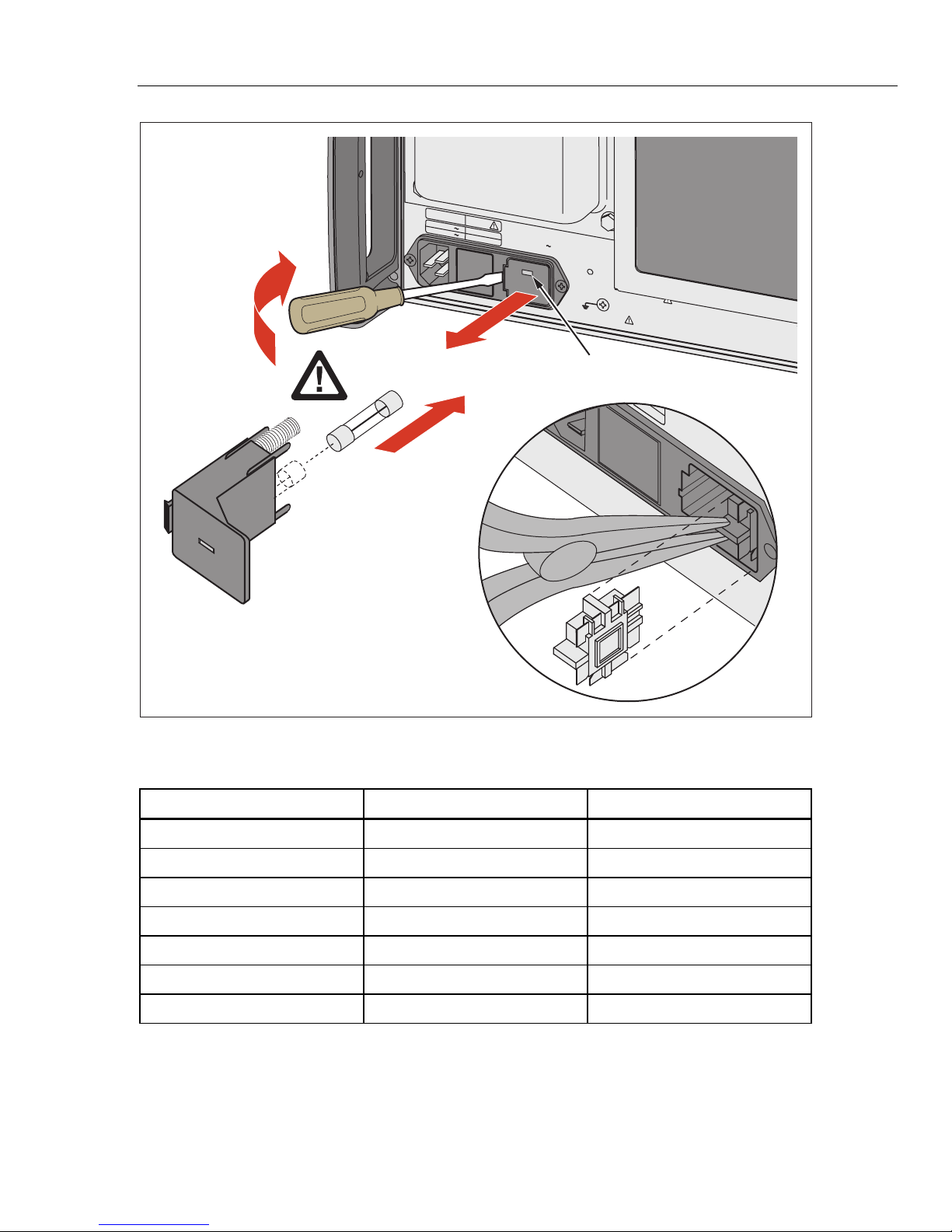
Preparing for Operations
WARNING:
TO AVOID PHYSICAL INJURY, INSURE THA
IS PROPERLY INSTALLED BEFORE ENERGIZING INSTRU
CAUTION
FOR FIRE PROTECTION REPLACE O
WITH A 250V FUSE OF INDICATED RATING
How to Select Line Frequency 2
MAINS SUPPLY
FUSE
100V/120V
220V/240V
T5.0A 250V
(SB)
T2.5A 250V
Changing Line Fuse
47Hz
(SB)
/63Hz
600VA MAX
CHASSIS
GROUND
WARNING:
CONNECTOR IN POWER CORD MUST BE CONNECTED
TO AVOID ELECTRIC SHOCK GROUNDING
Line Voltage
Indicator
0V
(SB)
Changing Line
Voltage
240
120
Figure 2-1. How to Access the Fuse and Select Line Voltage
Table 2-2. Line Power Cord Types Available from Fluke
Type Voltage/Current Fluke Option Number
North America 120 V/15 A LC-1
North America 240 V/15 A LC-2
Universal Euro 220 V/15 A LC-3
United Kingdom 240 V/13 A LC-4
Switzerland 220 V/10 A LC-5
120
gjh004.eps
Australia 240 V/10 A LC-6
South Africa 240 V/5 A LC-7
2-5
Page 52
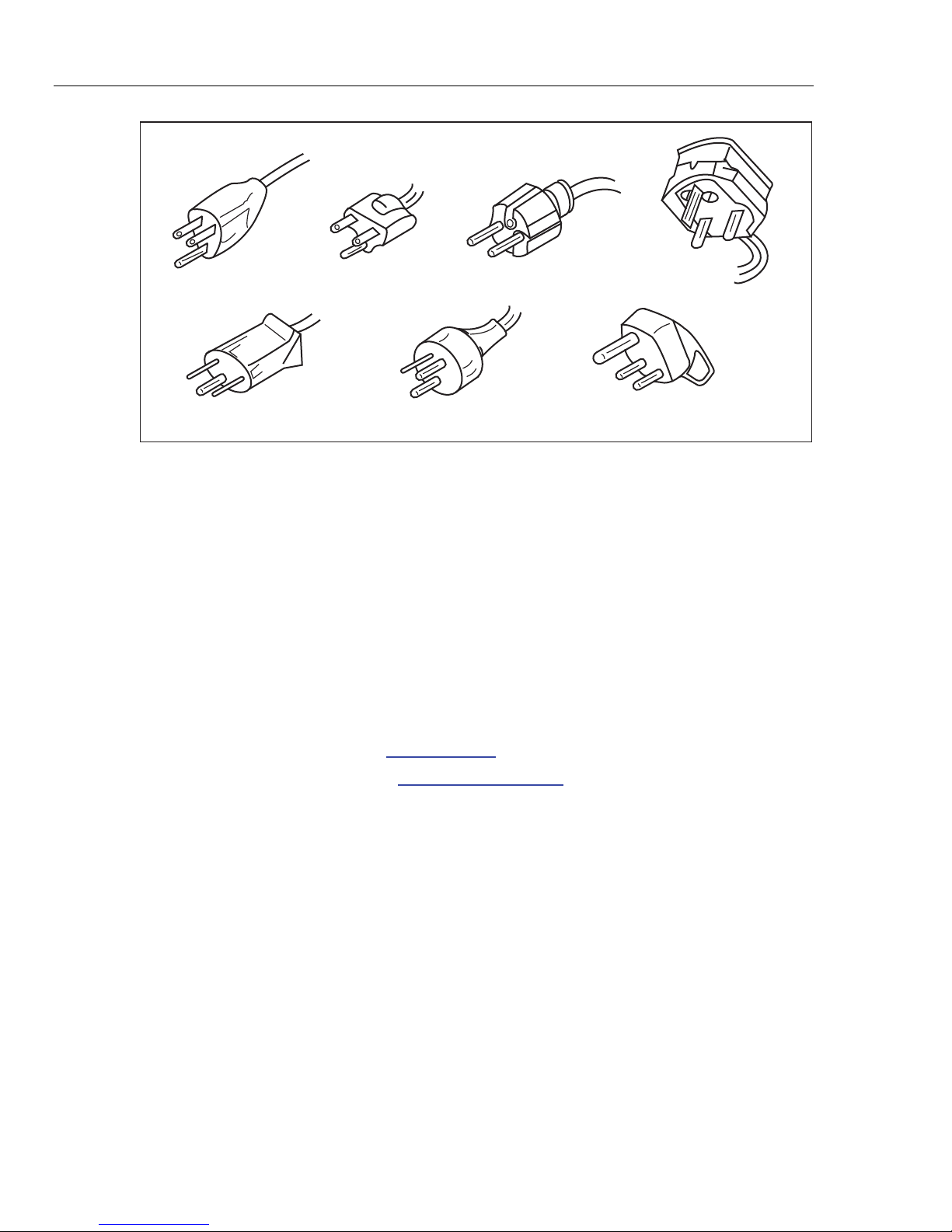
5522A
Operators Manual
How to Contact Fluke
LC-1 LC-2 LC-3 LC-4
LC-5 LC-6 LC-7
nn008f.eps
Figure 2-2. Line Power Cord Types Available from Fluke
To order accessories, receive operating assistance, or get the location of the nearest Fluke
distributor or Service Center, call:
USA: 1-888-99-FLUKE (1-888-993-5853)
Canada: 1-800-36-FLUKE (1-800-363-5853)
Europe: +31 402-675-200
Japan: +81-3-3434-0181
Singapore: +65-738-5655
Anywhere in the world: +1-425-446-5500
Or visit Fluke's Web site at www.fluke.com
To register this product, visit http://register.fluke.com
.
.
2-6
Page 53

Preparing for Operations
Placement 2
Placement
Warning
To prevent possible electrical shock, fire, or personal injury,
make sure that the Product is grounded before use.
You may place the calibrator on a bench top or mount it in a standard-width, 24-inch
(61-cm) deep equipment rack. For bench-top use, the calibrator is equipped with nonslipping, non-marring feet. To mount the calibrator in an equipment rack, use the 5522A
Rack Mount Kit, Model Y5537. Instructions for rack mounting the calibrator are packed
with the rack mount kit.
Cooling Considerations
Caution
To prevent damage to the Product, make sure the space around
the product meets minimum requirements.
Baffles direct cooling air from the fan throughout the chassis to internally dissipate heat
during operation. The accuracy and dependability of all internal parts of the calibrator are
enhanced by maintaining the coolest possible internal temperature. You can lengthen the
life of the calibrator and enhance its performance by observing the following rules:
• The area around the air filter must be at least 3 inches from nearby walls or rack
enclosures.
• The exhaust perforations on the sides of the calibrator must be clear of obstructions.
• The air entering the instrument must be at room temperature: make sure the exhaust
air from another instrument is not directed into the fan inlet.
• Clean the air filter every 30 days or more frequently if the calibrator is operated in a
dusty environment. (See Chapter 7, “Maintenance” for instructions on cleaning the
air filter.)
2-7
Page 54

5522A
Operators Manual
2-8
Page 55

Chapter 3
Features
Title Page
Introduction.......................................................................................................... 3-3
Front-Panel Features ............................................................................................ 3-3
Rear-Panel Features ............................................................................................. 3-3
Softkey Menu Trees............................................................................................. 3-3
3-1
Page 56

5522A
Operators Manual
3-2
Page 57

Introduction
This chapter is a reference for the functions and locations of the 5522A Calibrator's front
and rear-panel features. Please read this information before operating the calibrator. Front
panel operating instructions for the calibrator are provided in Chapter 4, “Front Panel
Operation”; remote operating instructions are provided in Chapter 5, “Remote
Operation”.
Front-Panel Features
Front-panel features (including all controls, displays, indicators, and terminals) are shown
in Figure 3-1. Each front-panel feature is described in Table 3-1.
Rear-Panel Features
Rear-panel features (including all terminals, sockets, and connectors) are shown in
Figure 3-2. Each rear-panel feature is described in Table 3-2.
Softkey Menu Trees
The Setup softkeys are identified in Figures 3-3 and 3-4. The Setup softkeys are
associated with the 5522A Calibrator front panel S key. The functions of the five
softkeys are identified by label information displayed directly above each key. The
softkey labels change during operation so that many different functions are quickly
accessible.
A group of softkey labels is called a menu. A group of interconnected menus is called a
menu tree. Figure 3-3 shows the SETUP menu tree structure; Figure 3-4 describes each
SETUP menu tree display. Table 3-3 shows the factory default settings for the SETUP
menu tree. To return the SETUP menus to their default values, use the softkey SETUP in
the Format NV Memory menu (see Figure 3-4, menu F).
3-3
Page 58
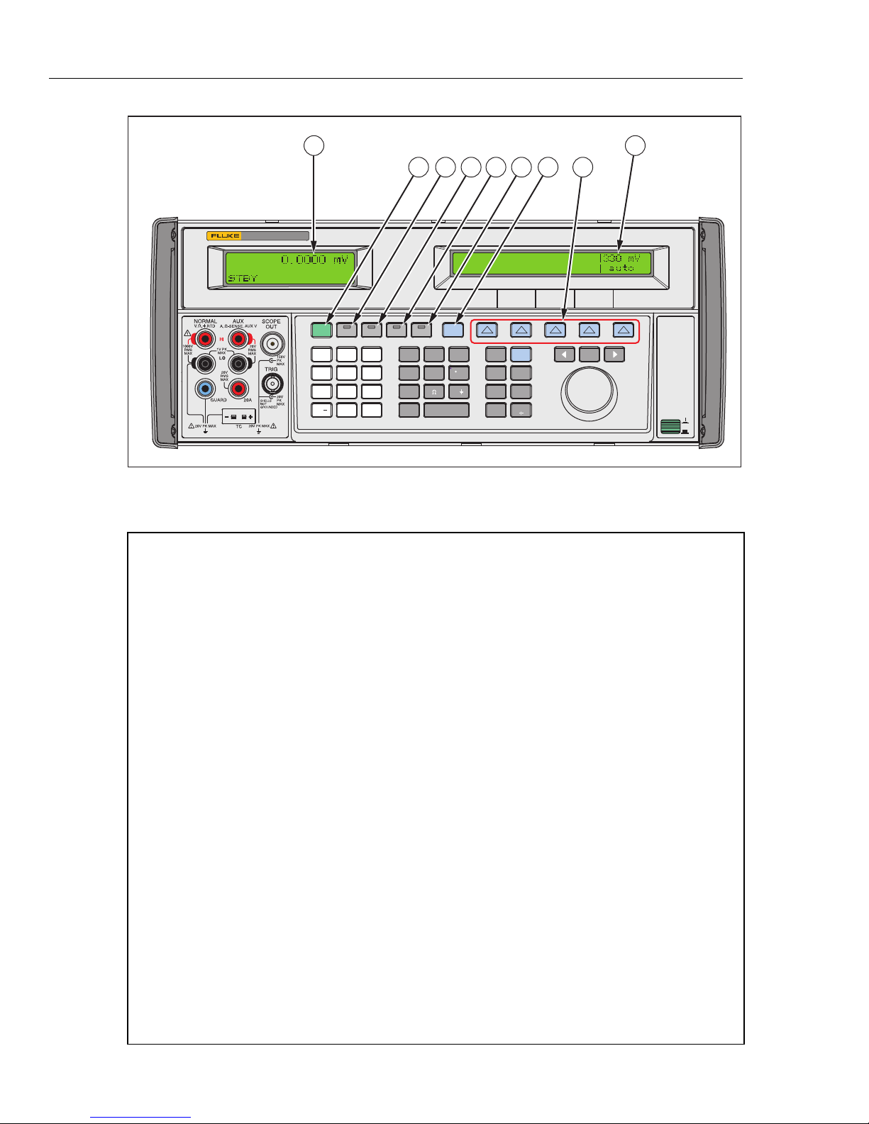
5522A
Operators Manual
5522A
1 2
3 4 5 6 7 8 9
CALIBRATOR
STBY
OPR EARTH SCOPEEXGRD
8 9
7
456
23
1
+
/
•
0
p
n
p
PREV
MENU
dBm sec
m
V Hz
W
A
ENTER
F
C
F
k
M
SHIFT
SETUP
NEW
REF
MEAS
TC
MULT
RESET
CE
MORE
MODES
DIV
x
EDIT
FIELD
POWER
Figure 3-1. Front-Panel Features
Table 3-1. Front-Panel Features
Output Display
The Output Display is a two-line backlit LCD that shows output amplitudes, frequency and calibrator
status. Output values (or potential output values if in standby) are displayed using up to seven digits
plus a polarity sign. Output frequencies (or potential output frequencies if the 5522A is in standby)
are displayed using four digits. Calibrator status is indicated by displaying the following
abbreviations:
OPR Displayed when an output is active at the front panel terminals.
STBY Displayed when the 5522A is in standby.
u When you change the output, a “u” (unsettled) is displayed until the output settles to
within the specified accuracy.
gjh005.eps
m Displayed when the calibrator is making a measurement. (Thermocouple, pressure, and
impedance measurement features only.)
? Displayed when the amplitude is specified as typical only, and/or reduced resolution. This
occurs when operating the 5522A in the extended bandwidth mode.
C Displayed when the amplitude is specified as typical only, and/or reduced resolution. This
occurs when operating the 5522A in the extended bandwidth mode.
Control Display
The Control Display is a multipurpose backlit LCD used for displaying data entries, UUT error
adjustments, softkey labels, phase angles, watts, power factors, and other prompts and messages.
When there isn’t enough room on the Output Display, output frequency is displayed on the Control
Display. Softkey labels identify the function of the softkey directly below them. Several softkey labels
together are called a menu. The changing menus provide access to many different functions through
the five softkeys plus the PREV MENU key. (See Figure3-3, Softkey Menu Tree.)
Y
The STBY (Standby) key places the 5522A in standby mode. Standby mode is indicated by “STBY”
3-4
Page 59

Features
Softkey Menu Trees 3
in the lower left corner of the Output Display. In standby mode, the NORMAL, AUX and 20A output
terminals are internally disconnected from the 5522A. The 5522A starts up in standby mode. The
5522A automatically switches to standby if one of the following occurs:
The RESET key is pressed.
A voltage ≥ 33 V is selected when the previous output voltage was less than 33 V.
Output function is changed, except when going between ac or dc voltage <33 V.
A current output above 3 A is selected. This is when the output location changes to the 20A
terminal.
An overload condition is detected.
O
The OPR (Operate) key places the 5522A in operate mode. Operate mode is indicated by “OPR” in
the lower left corner of the Output Display and the lit indicator on the OPR key.
Z
The EARTH (Earth Ground) key opens and closes an internal connection between the NORMAL LO
terminal and earth ground. An indicator on the key indicates when this connection is made. The
power-up default condition is earth disabled (indicator off).
a
The SCOPE (Oscilloscope) key activates or deactivates an oscilloscope calibration option if it is
installed. An indicator on the key indicates when the option is activated. If an oscilloscope calibration
option is not installed in the calibrator and the SCOPE key is pressed, the calibrator displays an
error message.
B
The EXGRD (External Guard) key opens and closes an internal connection between the internal
NORMAL LO signal ground and the internal guard shield. An indicator on the key indicates when
this connection is made. The power-up default condition is external guard disabled (indicator off)
P
The PREV MENU (Previous Menu) key recalls the previous set of menu choices. Each press of this
key backs up one level of the menu tree until the display indicates the top level menu selection of
the function selected.
Softkeys
The functions of the five unlabeled blue softkeys are identified by labels on the Control Display
directly above each key. The functions change during operation so that many different functions are
accessible through these keys. A group of softkey labels is called a menu. A group of interconnected
menus is called a menu tree.
3-5
Page 60
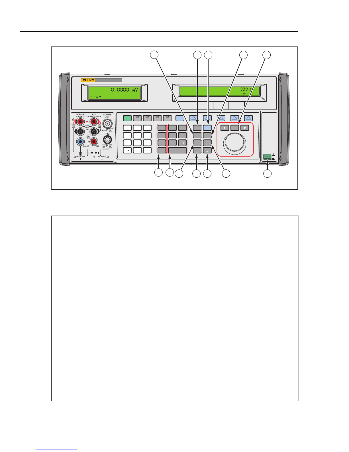
5522A
Operators Manual
5522A
CALIBRATOR
STBY
OPR EARTH SCOPEEXGRD
8 9
7
456
23
1
+
/
•
0
10
PREV
MENU
p
dBm sec
m
V Hz
n
W
k
A
p
M
ENTER
SHIFT
11 12 13 14
RESET
SETUP
F
NEW
REF
MEAS
MULT
CE
MORE
TC
MODES
DIV
x
C
F
21 20
Figure 3-1. Front-Panel Features (cont.)
Table 3-1. Front-Panel Features (cont.)
EDIT
FIELD
POWER
1619
151718
gjh009.eps
N
The NEW REF (New Reference) key is active during error mode operation, and establishes the
present output value as a new reference for meter error computation.
S
The SETUP (Setup Menu) key puts the 5522A in the setup mode, displaying the setup menu in the
Control Display. Setup options can be selected using the softkeys under the Control Display.
R
The RESET (Reset Calibrator) key aborts the current operating state of the 5522A and returns it to
the power-up default state, except when operating under remote control.
G
The CE (Clear Entry) key clears a partially completed keypad entry from the Control Display. If there
is a partially completed entry when CE is pressed, the output is unaffected.
L e W
The EDIT FIELD (Edit Output Display Field) key and associated left/right arrow keys provide step
adjustment of the output signals. If any of these keys are pressed or the knob is rotated, a digit on
the Output Display becomes highlighted and the output increments or decrements as the knob is
rotated. If a digit rolls past 0 or 9, the digit to its left or right is carried. An error display appears on
the Control Display, showing the difference between the original (reference) output and the new
output.
The L and W keys adjust the magnitude of changes by moving the highlighted digit. The
ekey allows you to move from voltage or current to frequency and back. In practice, for voltage
and current outputs, the knob and arrow keys are used to adjust output until the UUT reads
correctly. The error display then displays UUT deviation from the reference.
3-6
Page 61

Features
Softkey Menu Trees 3
The power switch turns the power on and off. The switch is a latching push-push type. When the
switch is latched in, power is on.
m
The MORE MODES key provides access to the measure pressure function. You need a Fluke 700
Series pressure module to measure pressure
D
The DIV (Divide) key immediately changes the output to 1/10th reference value (not necessarily the
present output value) if the value is within performance limits. In the SCOPE mode, the DIV key
changes the output to the next lower range.
X
The MULT (Multiply) key immediately changes the output to 10X the reference value (not
necessarily the present output value) if the value is within performance limits. This key sets the
5522A to standby if this change is from below 33 V. In the SCOPE mode, the MULT key changes
the output to the next higher range.
U
The MEAS TC (Measure Thermocouple) key enables the TC (Thermocouple) input connection and
causes the 5522A to compute a temperature based on the voltage present at the input.
Output Units Keys
The output units keys determine the function of the 5522A. Some keys have a second unit if the
SHIFT key is pressed just before the units key. The output units are as follows:
V Voltage or Decibels relative to 1 mW into 600 ohms
(impedance changeable).
A Watts or Current
Q Resistance
H Frequency or Seconds (Seconds is applicable to the SCOPE
functions only)
F Capcitance
C Temperature in Fahrenheit or Celsius
Multiplier Keys
Select output value multipliers. Some keys have a second function if the SHIFT key is pressed just
before the multiplier key. For example, if you enter 33, then SHIFT, then c, then F, then
ENTER, the 5522A output value is 33 pF. The multiplier keys are as follows:
c milli (10-3 or 0.001) or micro (10-6 or 0.000001)
K kilo (10
M mega (10
3
or 1,000) or nano (10
6
or 1,000,000) or pico (10
-9
or 0.000000001)
-12
or 0.000000000001)
3-7
Page 62
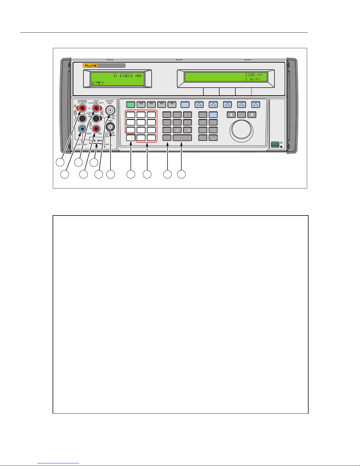
5522A
Operators Manual
5522A
CALIBRATOR
32 30
31 29 27
E
The ENTER key loads a newly entered output value shown on the Control Display into the 5522A,
which appears on the Output Display. The new value can come from the numeric keypad. If you
press ENTER without identifying the units for the entry, in most cases the 5522A keeps the units
that were last used. This allows you, for example, to enter 1 mV, and then later enter 10 to obtain 10
V. (The "V" units were saved from the last entry, but not the multiplier, "m".) In the Error (edit) mode,
ENTER with no value restores the output to the value of the reference
STBY
OPR EARTH SCOPEEXGRD
8 9
7
456
23
1
+
/
0
28
26 25 24 23 22
Figure 3-1. Front-Panel Features (cont.)
Table 3-1. Front-Panel Features (cont.)
PREV
MENU
p
dBm sec
m
V Hz
n
W
A
ENTER
F
C
F
k
p
M
SHIFT
•
SETUP
NEW
REF
MEAS
TC
MULT
RESET
CE
MORE
MODES
DIV
x
EDIT
FIELD
POWER
gjh010.eps
3-8
b
The SHIFT key selects alternate functions of the units keys and alternate multipliers of the multiplier
keys. These alternate selections are labeled with small letters in the upper left hand corner of the
keys
Numeric Keypad
Used to enter the digits of the output amplitude and frequency. The proper sequence to enter a
value is to press the digits of the output value, a multiplier key (if necessary), an output units key,
then ENTER. For example, to obtain an output of 20 mV, you would press the following sequence of
keys: 20cV. Press O to enable the output. Pressing a digit key once the entry field is
full, and pressing the decimal point key more than once in a single number will sound the beeper.
I
The I (Polarity) key changes the polarity of the output for dc voltage or dc current functions.
Press the I key then E to toggle the output polarity.
The SCOPE TRIG (Scope Trigger) BNC connector is used to trigger the oscilloscope during
oscilloscope calibration. This is active only when an oscilloscope option is installed.
The SCOPE OUT (Oscilloscope) Type N connector is used for outputs during oscilloscope
calibration. This is active only when an oscilloscope calibration option is installed.
Page 63

Features
Softkey Menu Trees 3
Table 3-1. Front-Panel Features (cont.)
The TC (Thermocouple) minijack is used for thermocouple simulation during thermometer
calibration, and thermocouple measurements. You must use the correct thermocouple wire and plug
when using this connector. For example, if simulating a type K thermocouple, use type K
thermocouple wire and type K plug for making connections
The 20A terminal is the source of current output when the 20 A range is selected (3 A - 20 A)
The AUX (Auxiliary Output) terminals are used for ac and dc current outputs, the second voltage
output in dual voltage modes, and ohms sense for 2-wire and 4-wire compensated resistance and
capacitance measurements, and RTD simulation
The GUARD terminal is always connected internally to the internal guard shield. This shield is tied to
the NORMAL LO signal ground inside the Calibrator unless the B key is pressed so that its
indicator is lit
The NORMAL (Normal Output) terminals are used for ac and dc voltage, ohms and capacitance
sourcing, and Resistance Temperature Detector (RTD) simulation.
3-9
Page 64
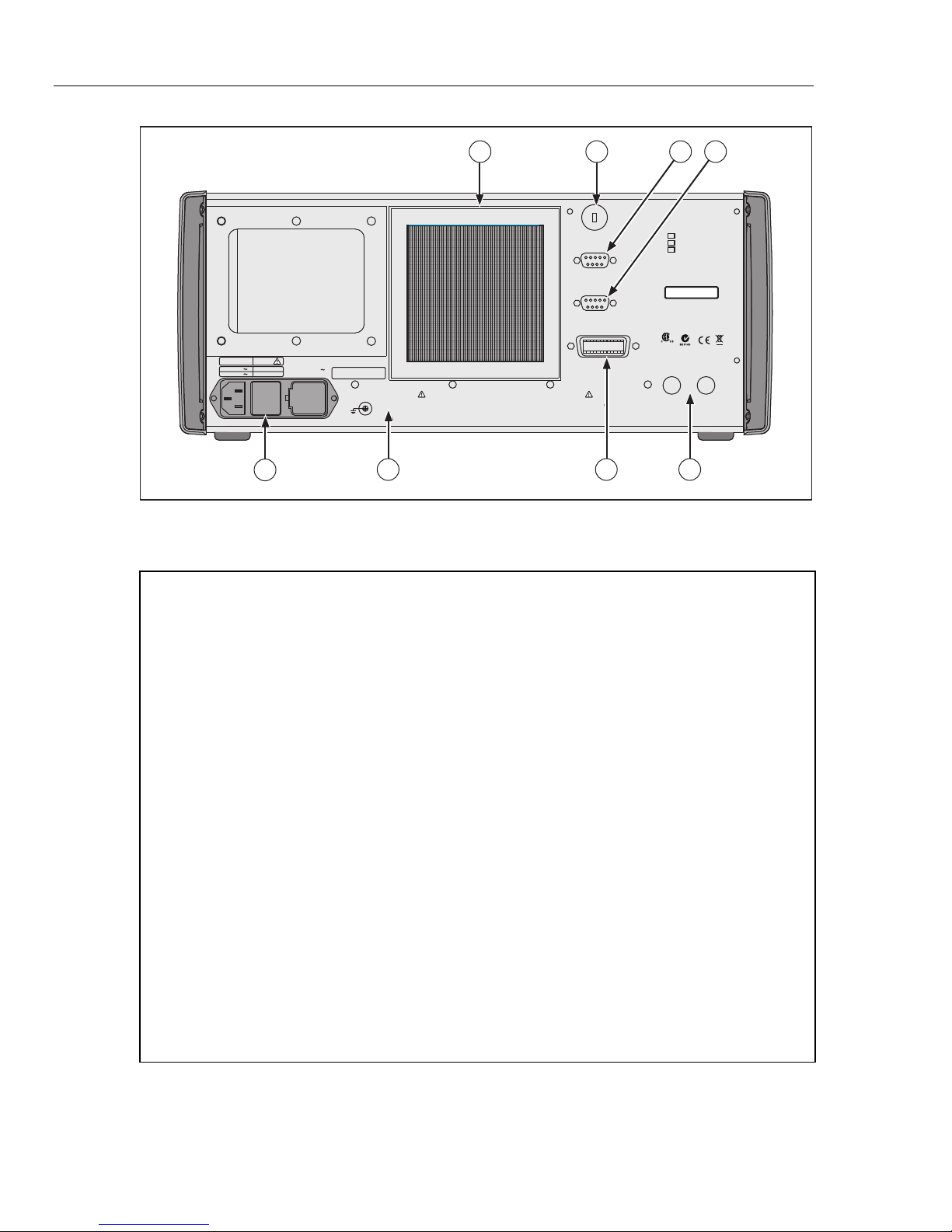
5522A
Operators Manual
MAINS SUPPLY
100V/120V
220V/240V
FUSE
T5.0A 250V
T2.5A 250V
8
(SB)
(SB)
CAUTION
FOR FIRE PROTECTION REPLACE ONLY
WITH A 250V FUSE OF INDICATED RATING
/63Hz 47Hz
600VA MAX
1 2
CALIBRATION
WARNING:
TO AVOID PHYSICAL INJURY, INSURE THAT THE FILTER
CHASSIS
GROUND
IS PROPERLY INSTALLED BEFORE ENERGIZING INSTRUMENT
TO AVOID ELECTRIC SHOCK GROUNDING
WARNING:
CONNECTOR IN POWER CORD MUST BE CONNECTED
7 56
NORMAL
ENABLE
SERIAL 2
TO UUT
SERIAL 1
FROM HOST
IEEE-488
TO CLEAN THE FILTER:
-UNPLUG INSTRUMENT
-REMOVE FILTER
-FLUSH WITH SOAPY WATER
-DRY BEFORE REINSTALLATION
3 4
INSTALLED
OPTIONS
- SC600
- SC1100
- PQ
FLUKE CORPORATION
EVERETT WA, USA
NO INTERNAL USER SERVICEABLE
PARTS. REFER SERVICE TO
QUALIFIED SERVICE PERSONNEL
LR65268C
(LEM CERTIFIED)
10MHZ
IN OUT
5V
PK - PK
MAX
Figure 3-2. Rear-Panel Features
Table 3-2. Rear-Panel Features
The Fan Filter covers the air intake to keep dust and debris out of the chassis air baffles. The
5522A fan provides a constant cooling air flow throughout the chassis. Instructions for fan filter
maintenance are in Chapter 7, Maintenance.
gjh011.eps
The CALIBRATION NORMAL/ENABLE slide switch is used to write enable and disable the
nonvolatile memory that stores calibration constants. Switching to ENABLE allows changes to be
written into memory, and switching to NORMAL protects data in memory from being overwritten. The
switch is recessed to allow it to be covered with a calibration sticker to guarantee calibration
integrity.
The SERIAL 2 TO UUT connector is used for transmitting and receiving RS-232 serial data between
the 5522A and a Unit Under Test (UUT) or a Fluke 700 Series pressure module. Chapter 6, “Remote
Commands” describes how to use the RS-232 serial interface for UUT communications. Chapter 4
described how to measure pressure.
The SERIAL 1 FROM HOST connector is used for remote control of the 5522A and for transmitting
internal-constant RS-232 serial data to a printer, monitor, or host computer. Chapter 5, “Remote
Operation” describes how to use the RS-232 serial interface for remote control.
The 10 MHz IN BNC connector is for applying an optional external clock signal to the 5522A. This
replaces the normal internal 10 MHz clock signal in the 5522A. Frequency accuracy of the 5522A is
governed by the frequency accuracy of the clock signal internal or external.
The 10 MHz OUT BNC connector passes the internal or external 10 MHz clock signal to another
5522A to synchronize one or more slave 5522As to a master 5522A.
The IEEE-488 connector is a standard parallel interface for operating the 5522A in remote control as
a Talker/Listener on the IEEE-488 bus. Refer to Chapter 5, “Remote Operation” for bus connection
and remote programming instructions.
3-10
Page 65

Features
Softkey Menu Trees 3
Table 3-2. Rear-Panel Features (cont.)
Warning
To avoid shock hazard, connect the factory supplied threeconductor line power cord to a properly grounded power
outlet. Do not use a two-conductor adapter or extension
cord; this will break the protective ground connection.
Use the rear-panel CHASSIS GROUND terminal for a
protective grounding wire if there is any question about
the effectiveness of instrument earth grounding through
the line power cord ground wire.
The CHASSIS GROUND terminal is internally grounded to the chassis. If the 5522A is the location
of the ground reference point in a system, this binding post can be used for connecting other
instruments to earth ground. Refer to “Connecting the Calibrator to a UUT” in Chapter 4, “Front
Panel Operation” for details
The AC Power Input Module provides a grounded three-prong connector that accepts the line
power cord, a switch mechanism to select the operating line voltage, and a line power fuse. See
Chapter 2, “Preparing for Operation” for information on selecting the operating line voltage, and fuse
rating and replacement information.
3-11
Page 66
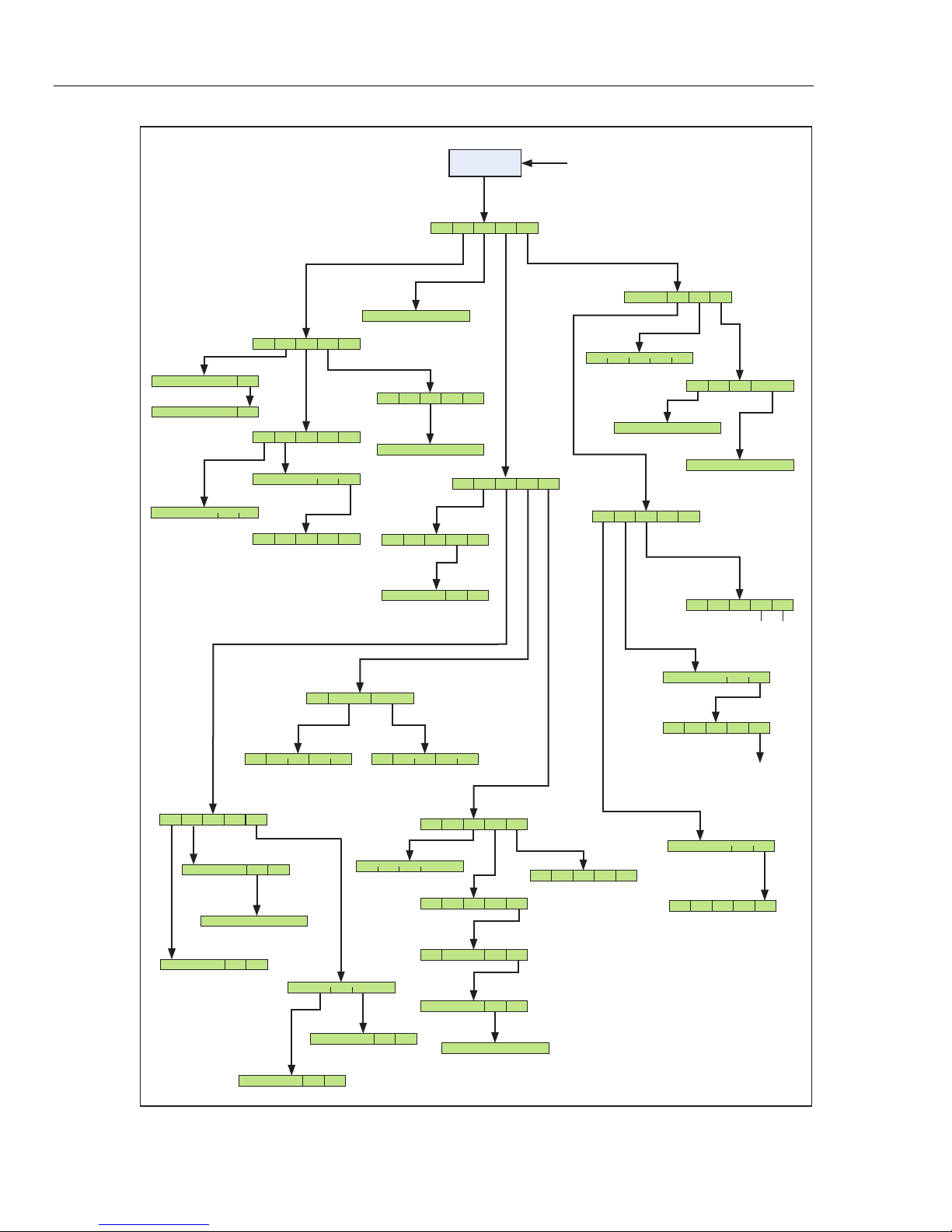
5522A
Operators Manual
Z
Y
AE
X
AC
AD
AF
SETUP
W
AA
AB
G2
Front Panel Key
A
B
F
C
E
D
G
AG
GI
AJ
S
S1
S2
S3
P
RQ
H
O
K
L
T
M
U
V
N
AK AL
AH
AF
Next
Section
AH
I
AF
3-12
Figure 3-3. Setup Softkey Menu Tree
gjh006.eps
Page 67
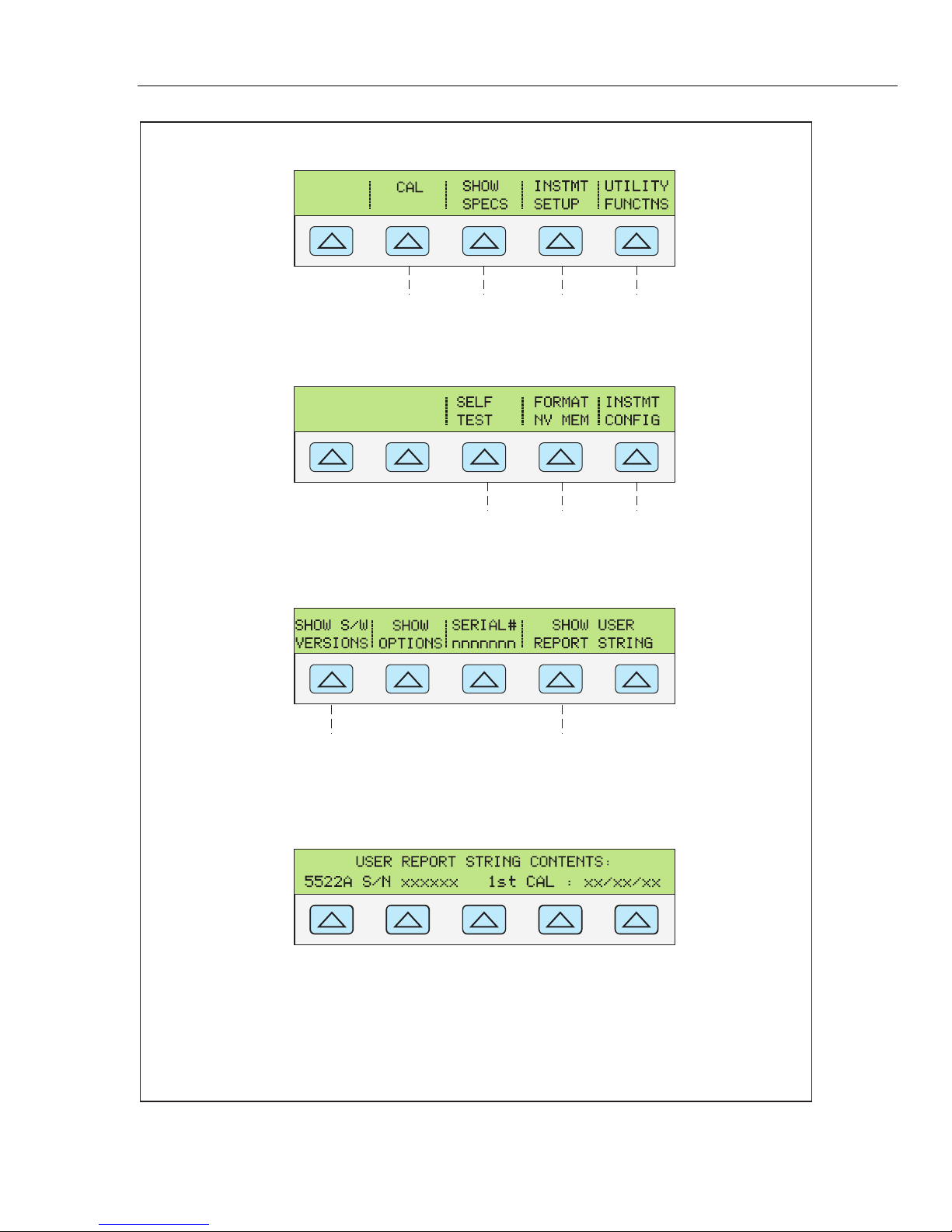
Features
Softkey Menu Trees 3
A
to X W to G to B
SHOW SPECS is an online summary of the programmed output specifications.
B
to AG
If self test does not pass, error codes are displayed. (See chapter 7, "Maintenance")
to F to C
C
to E to D
SERIAL # displays the serial number of the instrument. When corresponding with the factory,
always include the serial number of the instrument.
D
USER REPORT STRING CONTENTS refer to a string of characters entered by the user for
reporting purposes.
Figure 3-4. SETUP Softkey Menu Displays
gjh007.eps
3-13
Page 68
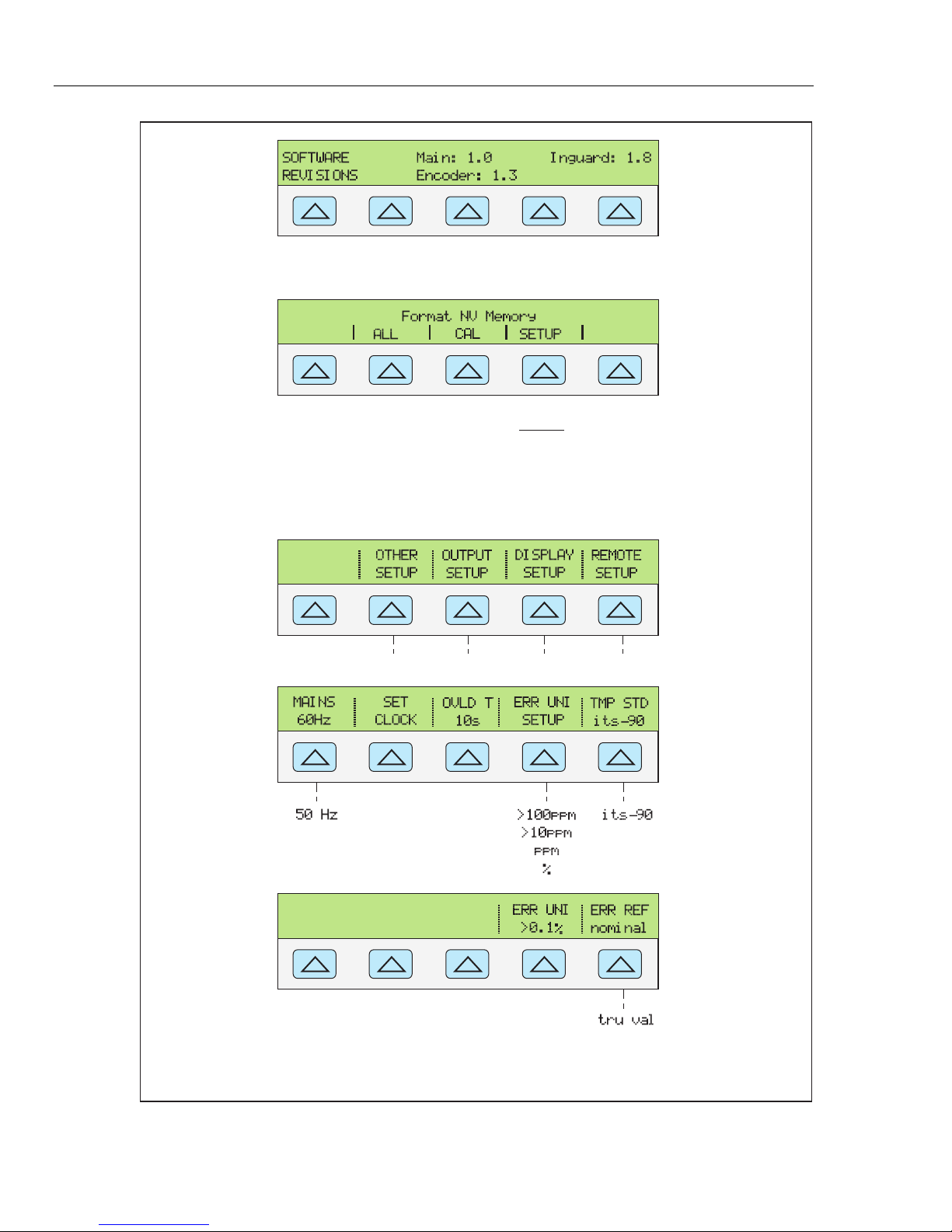
5522A
Operators Manual
E
Actual revision numbers replace the numbers in each of the above.
F
Format NV (non-volatile) Memory should be used with caution. Changes are non-reversible. The
softkeys function only when the rear-panel CALIBRATION switch is set to ENABLE, except for the
softkey SETUP, which is not dependent on the CALIBRATION switch position.
All sets all calibration and setup constants to factory setting. CAL set only calibration constants
to factory settings. SETUP resets instrument setup to factory default settings (see Table 3-3).
G
G1
G2
to S to P to Hto G1
TMP STD (temperature degree standard) refers to its-90 (1990 International Temperature
Standard) (factory default) and ipts-68 (1968 International Provisional Temperature Standard).
Figure 3-4. SETUP Softkey Menu Displays (cont.)
3-14
gjh008.eps
Page 69
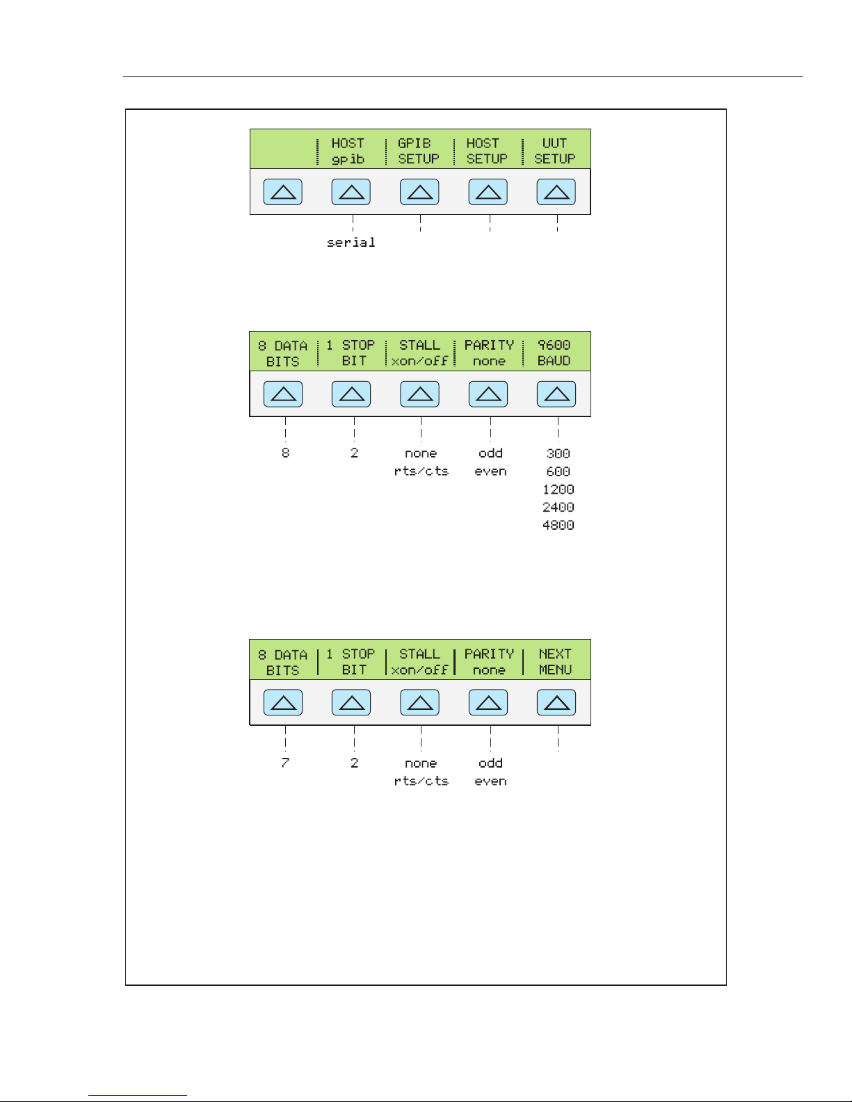
Features
Softkey Menu Trees 3
H
to K to Ito O
HOST selects the IEEE-488 (gpib) (factory default) parallel port or RS-232 (serial) port. You cannot
operate both IEEE-488 and RS-232 simultaneously.
I
STALL refers to the method of controlling data flow: software control (xon/off), hardware control
(rts/cts) or none.
K
to L
STALL refers to the method of controlling data flow: software control (xon/off), hardware control
(rts/cts) or none.
Figure 3-4. SETUP Softkey Menu Displays (cont.)
gjh030.eps
3-15
Page 70
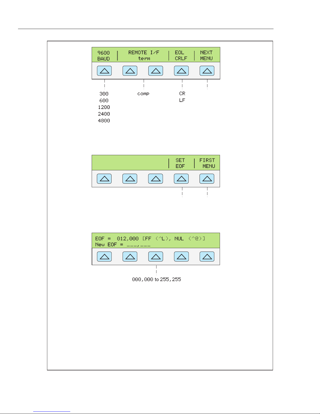
5522A
Operators Manual
L
to M
REMOTE I/F (Interface) has selections term (terminal) (factory default) and comp (computer). EOL
(End of Line character) is either Carriage Return/Line Feed (CRLF), CR (Carriage Return) or LF
(Line Feed).
M
to N to K
EOF (End of File) indicates the action taken at the end of a file by entering one or two ASCII
characters.
N
EOF (End of File) ASCII characters are entered with a range of 000 to 255 (first character) and 000
to 255 (second character). The factory defaults are 012,000, where the FF (form feed) character
signals an advance to the next page, and the NULL (ignore) character holds position. When the
NULL character is 000 (^@), then effectively the EOF is only the FF character, or ^L for the factory.
Figure 3-4. SETUP Softkey Menu Displays (cont.)
3-16
gjh003.eps
Page 71
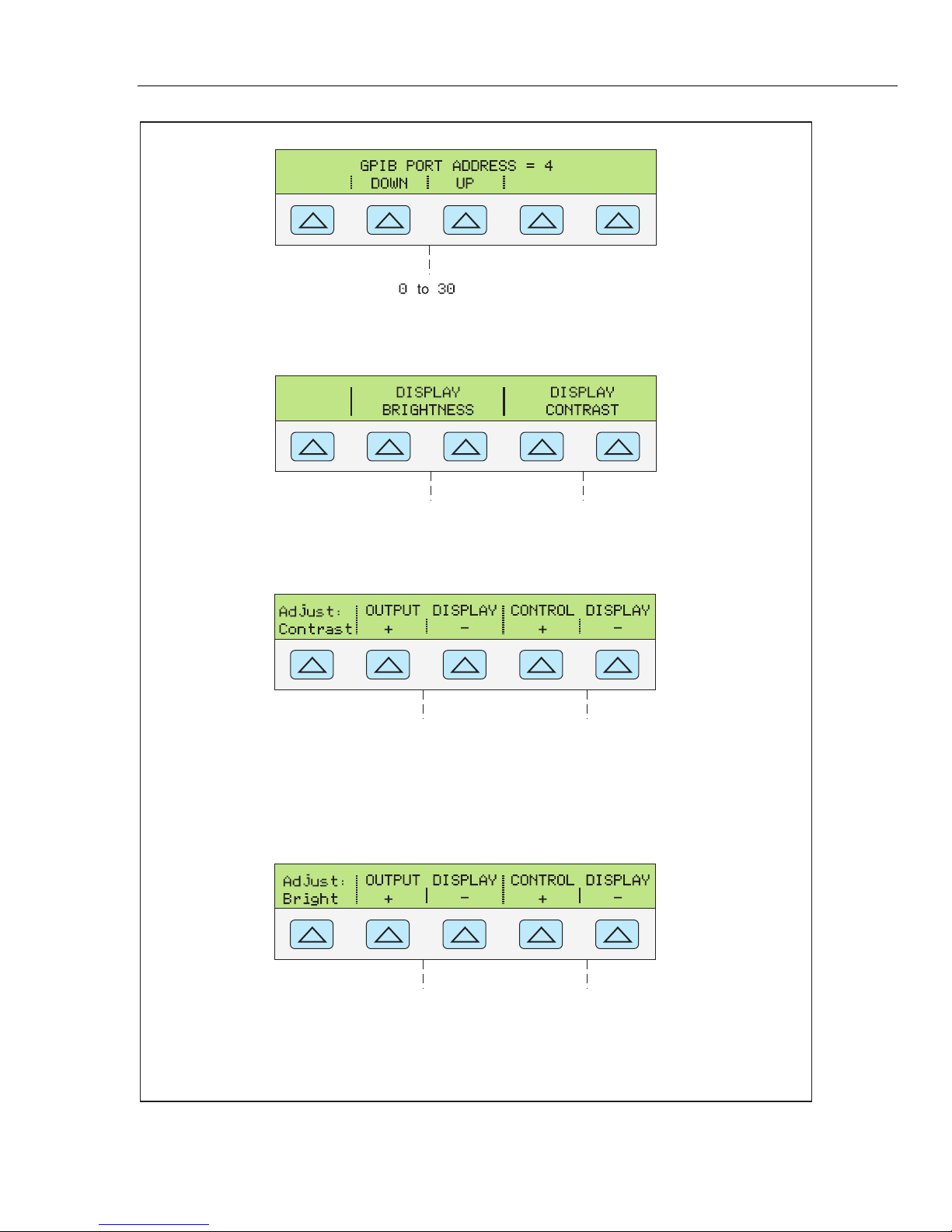
Features
Softkey Menu Trees 3
O
GPIB (General Purpose Interface Bus) selects the port address when using the IEEE-488 bus. The
factory default is 4.
P
to R to Q
DISPLAY BRIGHTNESS and DISPLAY CONTRAST apply to both the Output Display and Control
Display.
Q
levels 0,1,2,3,4,5,6,7 levels 0,1,2,3,4,5,6,7
There are eight levels of contrast, 0 to 7, for the Output Display and Control Display. Each may
have its own level of contrast. The factory defaults are 7 and 7.
R
There are eight levels of brightness, 0 to 7, for the Output Display and Control Display. Each may
have its own level of contrast. The factory defaults are 1 and 0.
Figure 3-4. SETUP Softkey Menu Displays (cont.)
levels 0,1,2,3,4,5,6,7 levels 0,1,2,3,4,5,6,7
gjh031.eps
3-17
Page 72
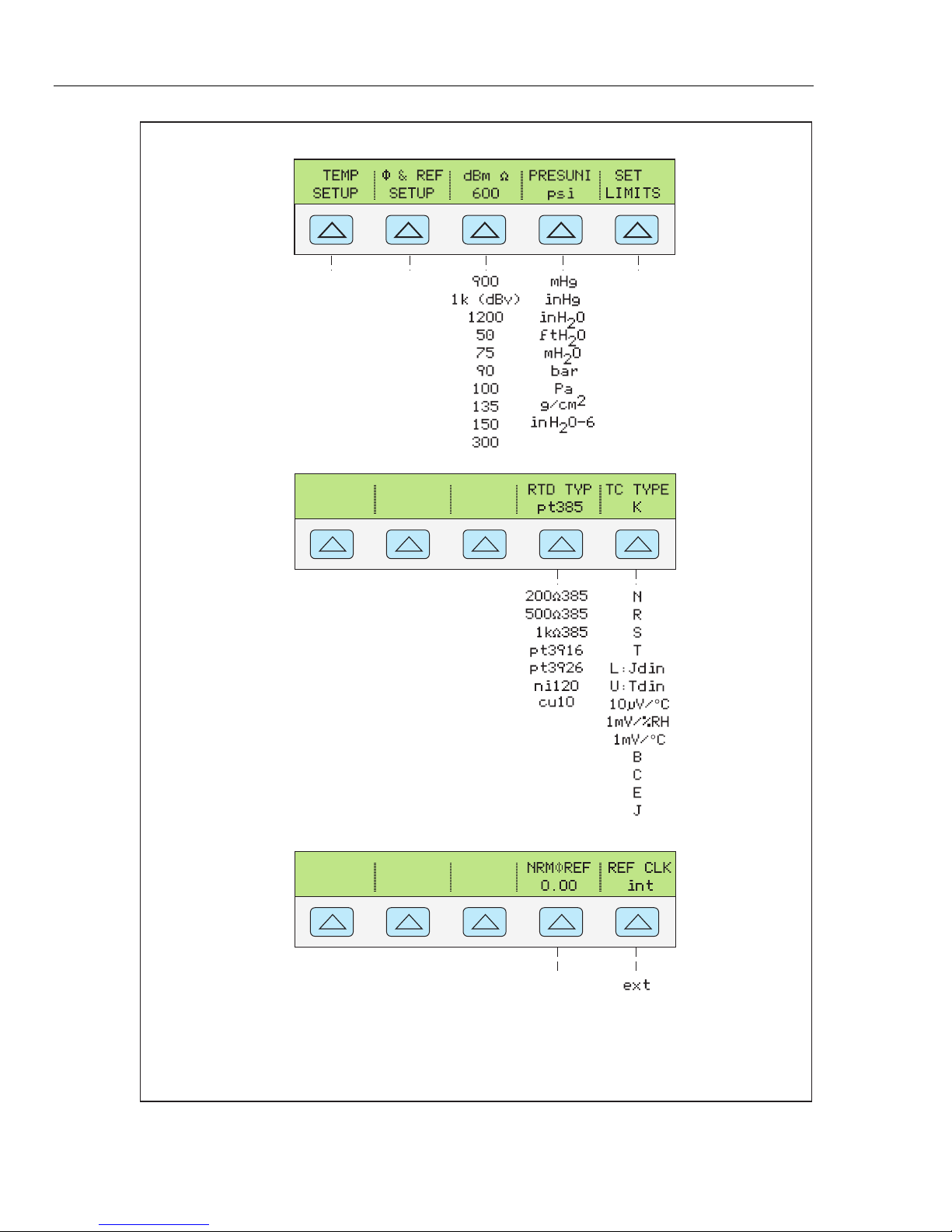
5522A
Operators Manual
S
to S2 to Tto S1
S1
S2
to S3
Figure 3-4. SETUP Softkey Menu Displays (cont.)
3-18
gjh032.eps
Page 73
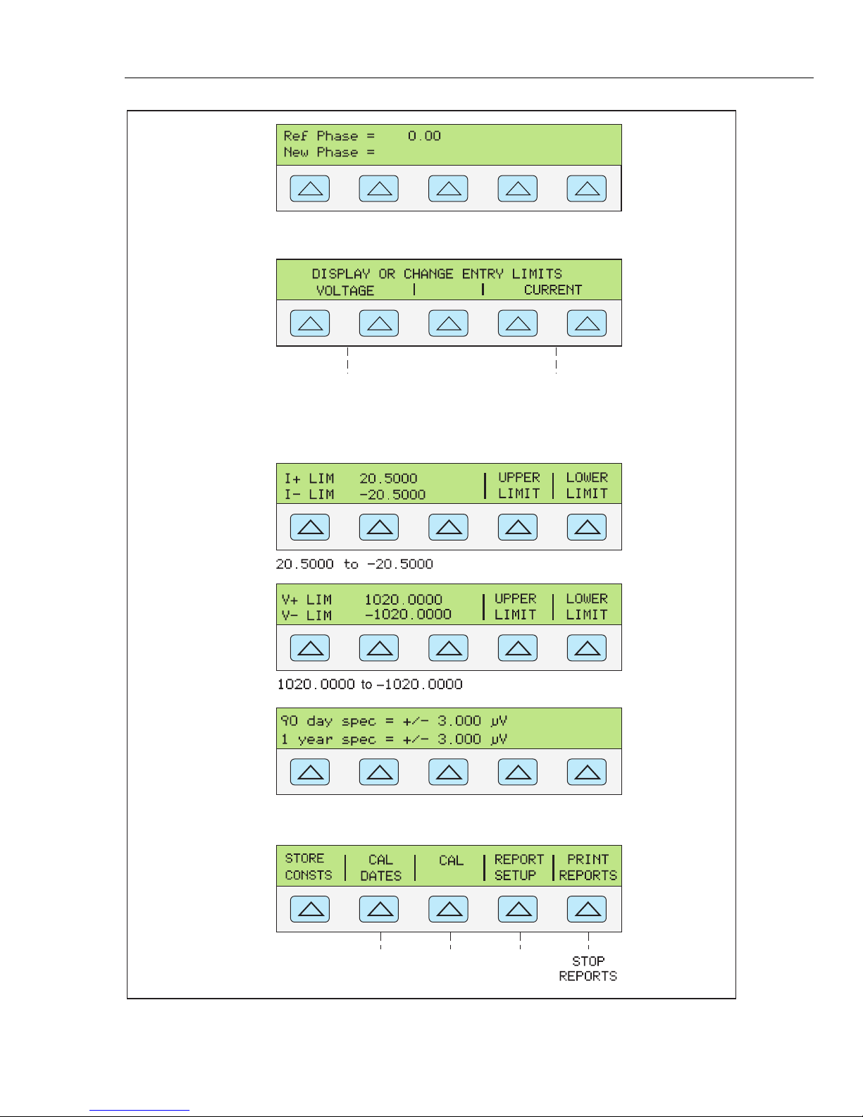
Features
Softkey Menu Trees 3
S3
T
to V to U
The values set here become the new limits and can be changed only with new entries or
returned to factory defaults using Format NV Memory SETUP (see menu F).
U
V
W
SHOW SPECS is an online summary of the programmed output specifications.
X
Figure 3-4. SETUP Softkey Menu Displays (cont.)
to ACto Y
to AA
gjh012.eps
3-19
Page 74
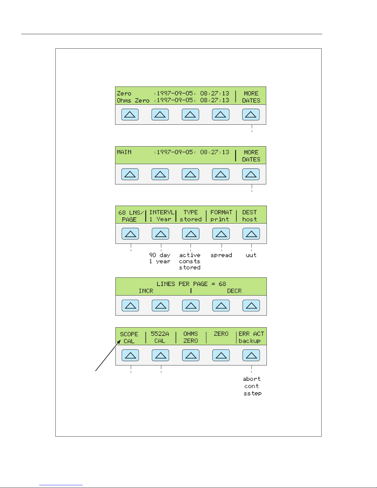
5522A
Operators Manual
Select the desired CAL (Calibration) feature: CAL to calibrate the 5522A (see the Service
Manual); CAL DATES to review when the 5522A Calibrator was last calibrated;
CAL REPORTS to printout the calibration data.
Y
to Z
Z
to X
AA
AB
AC
(Only if scope
option installed)
to AB
to ADto AE
5522A CAL opens the calibration menu. Refer to the Service Manual for instructions.
ZERO zeros the 5522A Calibrator. OHMS ZERO zeros the ohms portion of the 5522A
Calibrator; ERR ACT (Error Action) set backup, abort, or cont (continue).
Figure 3-4. SETUP Softkey Menu Displays (cont.)
3-20
gjh013eps
Page 75
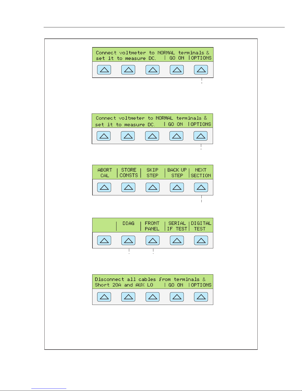
Features
Softkey Menu Trees 3
AD
to AF
GO ON and ABORT softkeys are used in the 5522A Calibrator calibration procedure. See the
Service Manual for more information.
(Only if scope
option installed)
AE
to AF
AF
AG
AH
to AG
to AH to AJ
Figure 3-4. SETUP Softkey Menu Displays (cont.)
gjh033.eps
3-21
Page 76
5522A
Operators Manual
Table 3-3. Factory Defaults for SETUP Menus Power-Up Defaults
Parameter Setting
User report string (*PUD
string)
Error units > 0.1% G1
SC-600 option overload test
safety timeout
Temperature standard its-90 G1
Host interface gpib (IEEE-488) G1
UUT serial interface 8 bits, 1 stop bit, xon/xoff, parity none,
Host serial interface term, 8 bits, 1 stop bit, xon/xoff, parity
GPIB Port Address 4 O
Display brightness (Note) level 1,0 P
Display contrast (Note) level 7,7 P
dBm impedance 600 Ω S
Pressure units psi S
Cleared. D
10 s G1
9600 baud
none, 9600 baud, CRLF, 012,000
SETUP Menu
(Figure 3-4.)
I
K, L, M, N
RTD type pt385 S1
Thermocouple type K S1
Phase reference 0.00° S3
10 MHz reference clock internal S2
Current limits ±20.5 A U
Voltage limits ±1020 V V
Note:
Output Display and Control Display, respectively. There are 8 levels: 0,1,2,3,4,5,6, and 7
3-22
Page 77

Chapter 4
Front Panel Operation
Title Page
Introduction.......................................................................................................... 4-3
How to Turn on the Calibrator............................................................................. 4-3
Warming up the Calibrator .................................................................................. 4-4
How to Use the Softkeys ..................................................................................... 4-4
How to Use the Setup Menu ................................................................................ 4-4
How to Use the Instrument Setup Menu ......................................................... 4-5
Utility Functions Menu.................................................................................... 4-6
How to Use the NV Memory Menu ................................................................ 4-6
How to Reset the Calibrator................................................................................. 4-7
How to Zero the Calibrator.................................................................................. 4-7
Operate and Standby Modes ................................................................................ 4-8
How to Connect the Calibrator to a UUT ............................................................ 4-8
Recommended Cable and Connector Types.................................................... 4-9
When to Use EARTH and EXGRD ................................................................ 4-9
Earth ............................................................................................................ 4-9
External Guard ............................................................................................ 4-10
Four-Wire versus Two-Wire Connections ...................................................... 4-10
Four-Wire Connection ................................................................................ 4-10
Two-Wire Compensation ............................................................................ 4-10
Compensation Off ....................................................................................... 4-10
Cable Connections Instructions....................................................................... 4-10
RMS Versus p-p Amplitude................................................................................. 4-16
Auto Range Versus Locked Range ...................................................................... 4-17
How to Set Output ............................................................................................... 4-17
How to Set DC Voltage Output....................................................................... 4-18
How to Set AC Voltage Output....................................................................... 4-19
How to Set DC Current Output ....................................................................... 4-22
How to Set AC Current Output ....................................................................... 4-23
How to Set DC Power Output ......................................................................... 4-24
How to Set AC Power Output ......................................................................... 4-26
How to Set a Dual DC Voltage Output ........................................................... 4-29
How to Set a Dual AC Voltage Output ........................................................... 4-30
How to Set Resistance Output......................................................................... 4-33
How to Set Capacitance Output....................................................................... 4-34
How to Set Temperature Simulation (Thermocouple) .................................... 4-35
How to Set Temperature Simulation (RTD).................................................... 4-38
How to Measure Thermocouple Temperatures ............................................... 4-39
Waveform Types.................................................................................................. 4-41
4-1
Page 78

5522A
Operators Manual
Sine Wave........................................................................................................ 4-41
Triangle Waves................................................................................................ 4-42
Square Wave.................................................................................................... 4-42
Truncated Sine Wave ...................................................................................... 4-43
How to Set Harmonics......................................................................................... 4-43
How to Adjust the Phase...................................................................................... 4-44
How to Enter a Phase Angle............................................................................ 4-46
How to Enter a Power Factor .......................................................................... 4-46
How to Enter a DC Offset.................................................................................... 4-47
Editing and Error Output Settings........................................................................ 4-48
How to Edit the Output Setting ....................................................................... 4-48
How to Display the UUT Error ....................................................................... 4-49
How to Use Multiply and Divide .................................................................... 4-50
How to Set Output Limits.................................................................................... 4-50
How to Set Voltage and Current Limits .......................................................... 4-50
How to Measure Pressure .................................................................................... 4-51
How to Synchronize the Calibrator using 10 MHz IN/OUT ............................... 4-52
How to Use an External 10 MHz Clock .......................................................... 4-52
How to Source AC Current and Parallel-Connected 5522As.......................... 4-53
Three-Phase Power Calibration....................................................................... 4-54
Sample Applications ............................................................................................ 4-55
How Calibrate an 80 Series Digital Multimeter .............................................. 4-55
Cables.......................................................................................................... 4-56
EARTH Connection .................................................................................... 4-56
How to Test the Meter................................................................................. 4-56
How to Calibrate the Meter......................................................................... 4-60
How to Test a Model 41 Power Harmonics Analyzer..................................... 4-60
How to Test Watts, VA, VAR Performance ............................................... 4-60
How to Test Harmonics Volts Performance ............................................... 4-62
How to Test Harmonics Amps Performance............................................... 4-63
How to Calibrate a Fluke 51 Thermometer ..................................................... 4-64
How to Test the Thermometer .................................................................... 4-64
How to Calibrate the Thermometer............................................................. 4-65
4-2
Page 79

Introduction
Warning
The Calibrator is capable of supplying lethal voltages. To avoid
shock hazard, do not make connections to the output terminals
when any voltage is present. Placing the instrument in standby
may not be enough to avoid shock hazard, since the O key
could be pressed accidentally. Press the R key and verify
that the Calibrator is in standby before making connections to
the output terminals.
This chapter presents instructions for operating the Calibrator from the front panel. For a
description of front panel controls, displays, and terminals, see Chapter 3, “Features.”
How to Turn on the Calibrator
Warning
To prevent possible electrical shock, fire, or personal injury,
make sure that the product is grounded before use.
Caution
Before turning the Calibrator on, make sure that the line voltage
selection is set properly. Refer to “Selecting Line Voltage” in
Chapter 2 to check the line voltage setting.
When the Calibrator is powered, the initial display is “Starting Up...” (see below) and it
completes a self-test routine. If a self-test fails, the Control Display identifies an error
code. For a description of error codes, see Chapter 7, “Maintenance.”
4-3
Page 80
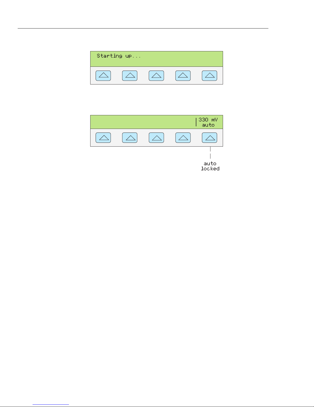
5522A
Operators Manual
After self-test, the control display shows the reset condition (below).
For a discussion of the softkey selection shown above (auto/locked), see “Auto Range
Versus Locked Range” later in this chapter.
Warming up the Calibrator
When you turn on the Calibrator, allow a warm-up period of at least 30 minutes for the
internal components to stabilize. This ensures that the calibrator meets or exceeds the
specifications listed in Chapter 1.
nn062f.eps
nn063f.eps
If you turn the Calibrator off after warm-up and then on again, allow a warm-up period of
at least twice the length of time it was turned off (maximum of 30 minutes). For example,
if the calibrator is turned off for 10 minutes and then on again, allow a warm-up period of
at least 20 minutes.
How to Use the Softkeys
The five keys just to the right of the P (Previous Menu) key are called softkeys.
Softkey key functions are based on the label that appears directly above the key in the
Control Display. Pressing a softkey either changes a value or causes a submenu with new
selections to appear on the Control Display. Softkey menus are arranged in varying
levels, as described in “Softkey Menu Tree” in Chapter 3. You can move backwards to
previous menu selections by repeatedly pressing P. Although pressing R will also
return you to the top level menu, it will also reset all volatile settings and return the
Calibrator to 0 V dc in the standby mode. Use the P key as your main navigating tool
for moving around the menu levels.
How to Use the Setup Menu
Press the front panel S key for access to various operations and changeable
parameters. Most parameters are nonvolatile, meaning they will be saved during reset or
when power is turned off. Chapter 3 shows a map of the menu tree, lists the parameters,
and has a table of factory default settings.
When you press S from the power-up state, the display changes as follows:
4-4
Page 81
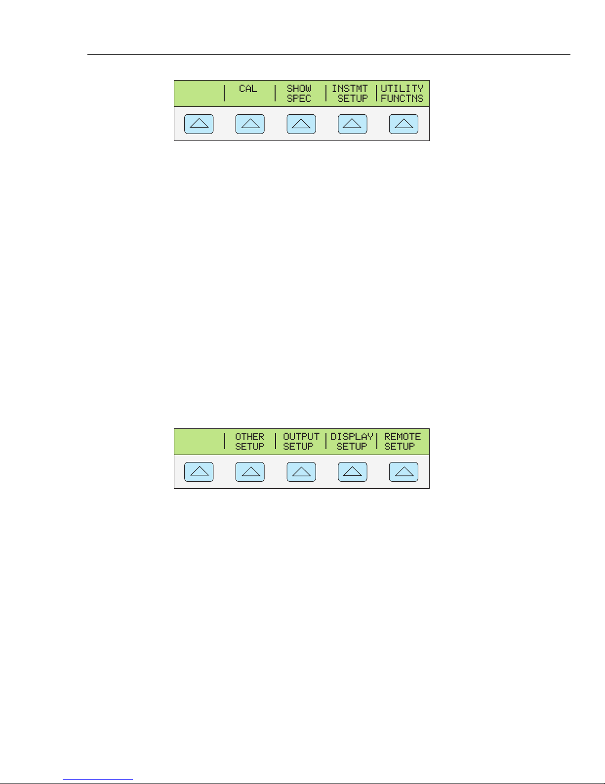
Front Panel Operation
How to Use the Setup Menu 4
This is the primary instrument setup menu. The list below describes submenus available
through each softkey and tells you where you can find further information in the manuals.
• CAL (Calibration) Opens the calibration menu. You use softkeys in this menu to
view the calibration dates, print a calibration report, and perform calibration, and to
run the Zero calibration routine. Zero calibration is described later in this chapter.
• SHOW SPECS (Show Specifications) Displays published Calibrator specifications
for the output value that is currently selected.
• INSTMT SETUP (Instrument Setup) Lets you change the power-up or reset default
setting for various instrument parameters. Many of the same parameters in this menu
can be changed during operation, but the changes you make during operation are
volatile. Changing them here makes them nonvolatile. To restore factory defaults,
use the Format NV Memory menu under the UTILITY FUNCTNS menu.
• UTILITY FUNCTNS (Utility Functions) Allows you to initiate self-tests, format
the nonvolatile memory (restore factory default settings), and review the instrument
configuration software versions and user report string. These features are explained
under “Utilities Function Menu” later in this chapter.
How to Use the Instrument Setup Menu
The softkeys in the instrument setup menu (accessed by pressing INSTMT SETUP
softkey in the Setup Menu) are shown below.
nn064f.eps
nn065f.eps
The list below describes submenus accessed by each softkey.
• OTHER SETUP Opens a menu that lets you toggle the degree reference between
the 1968 International Provisional Temperature Standard (ipts-68) and the 1990
International Temperature Standard (its-90) (factory default). This is also where you
set the clock, and set the power-up and reset defaults for the SC-600 Oscilloscope
Calibration Options’s Overload test safety timeout function (OVLD T), and
displayed error units. You may also configure the instrument for best operation with
a 50 Hz line frequency.
• OUTPUT SETUP Opens a menu to change the power-up and reset defaults for
current and voltage output limits, default thermocouple and RTD types, set the phase
reference, internal or external phase reference source, impedance for dBm display,
and pressure units.
• DISPLAY SETUP Opens submenus to set the brightness and contrast of both the
Control Display and Output Display.
• REMOTE SETUP Allows you to change the configuration of the two RS-232
ports, SERIAL 1 FROM HOST and SERIAL 2 TO UUT, and IEEE-488 General
Purpose Interface Bus (GPIB). (See Chapter 5, “Remote Operation” for more
information.)
4-5
Page 82
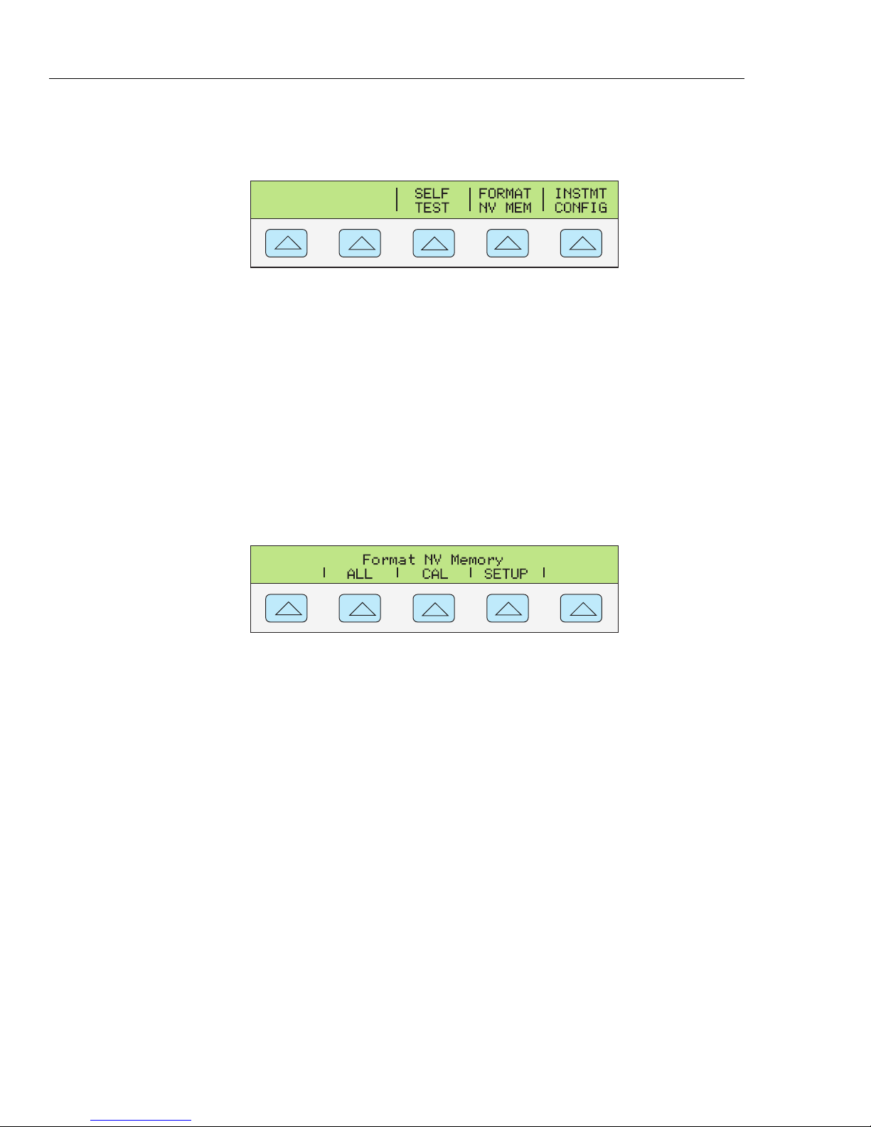
5522A
Operators Manual
Utility Functions Menu
The Setup Menu softkey labeled UTILITY FUNCTNS (Utility Functions) provides
access to Self Test, Format Nonvolatile Memory, and Instrument Configuration.
• SELF TEST This softkey opens a menu with calibrator self-test choices.
• FORMAT NV MEM (Format Nonvolatile Memory) Opens a menu to restore all or
part of the data in the nonvolatile memory (EEPROM) to factory defaults.
• INSTMT CONFIG (Instrument Configuration) Allows you to view the versions of
software installed in the calibrator as well as the user-entered report string.
How to Use the NV Memory Menu
Use with extreme care. The format nonvolatile memory menu
softkeys permanently erase calibration constants. Pressing
ALL or CAL invalidates the state of calibration of the 5522A.
Pressing FORMAT NV MEM in the utility functions menu opens the following:
The ALL and CAL softkeys in this menu require the rear-panel CALIBRATION switch
to be in the ENABLE position. The nonvolatile memory contains calibration constants
and dates, setup parameters, and the user report string. In the case of calibration
constants, factory defaults are the same for all Calibrators. They are not the calibration
constants obtained when the Calibrator was calibrated by the factory before shipment.
The softkeys are:
Caution
nn066f.eps
nn067f.eps
• ALL replaces the entire contents of the EEPROM with factory defaults. This would
be used by service personnel after replacing the EEPROM, for example. It is not
required in normal use.
• CAL replaces all calibration constants with factory defaults but leaves all the setup
parameters unchanged. This is also not required in normal use.
• SETUP replaces the setup parameters with factory defaults (Table 3-3) but leaves
the state of calibration unchanged. You do not have to break the calibration sticker
for this operation. Remote commands can also change the setup parameters. (See
these commands in Chapter 6: SRQSTR, SPLSTR, *PUD, SP_SET, UUT_SET,
TEMP_STD, DATEFMT, PRES_UNIT_D, RTD_TYPE_D, TC_TYPE_D, LIMIT.)
4-6
Page 83
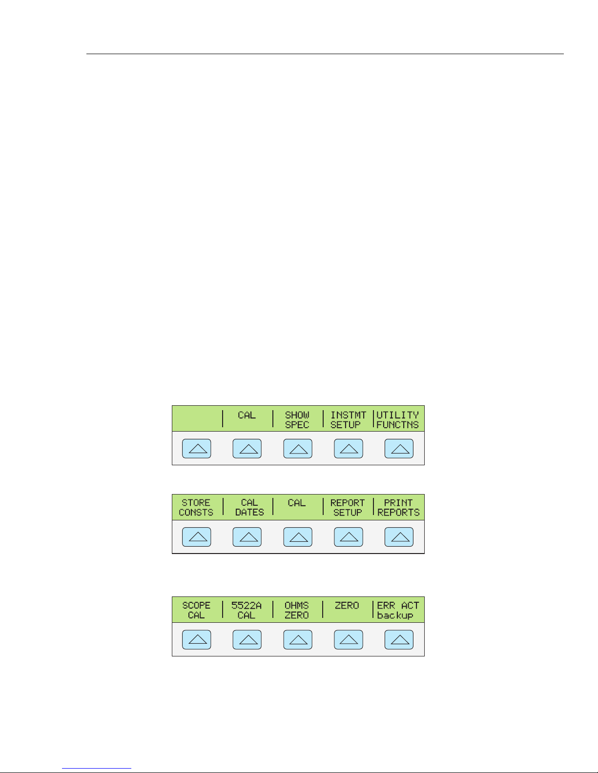
Front Panel Operation
How to Reset the Calibrator 4
How to Reset the Calibrator
At any time during front panel operation (not remote operation), you can return the
Calibrator to the power-up state by pressing R, except after an error message, which is
cleared by pressing a blue softkey. Pressing the R key does the following:
• Returns the calibrator to the power-up state: 0 V dc, standby, 330 mV range and all
OUTPUT SETUP menus set to their most recent default values.
Clears the stored values for limits and error mode reference.
How to Zero the Calibrator
Zeroing recalibrates internal circuitry, most notably dc offsets in all ranges of operation.
To meet the specifications in Chapter 1, zeroing is required every seven days, or when
the Calibrator ambient temperature changes by more than 5 °C. The tightest ohms
specifications are maintained with a zero cal every 12 hours within ±1 °C of use. The
Calibrator displays a message when it is time to zero the calibrator. Zeroing is
particularly important when your calibration workload has 1 mΩ or 1 μV resolution, and
when there has been a significant temperature change in the Calibrator work
environment. There are two zeroing functions: total instrument zero (ZERO) and ohmsonly zero (OHMS ZERO).
Complete the following procedure to zero the calibrator. (Note: The Calibrator rear-panel
CALIBRATION switch does not have to be enabled for this procedure.)
1. Turn on the Calibrator and allow a warm-up period of at least 30 minutes.
2. Press the R key.
3. Press the S key, opening the setup menu (below).
nn068f.eps
4. Press the CAL softkey, opening the calibration information menu (below).
nn069f.eps
5. Press the CAL softkey, opening the calibration activity menu (below). SCOPE CAL
appears as an option if it is installed.
6. Press the ZERO softkey to totally zero the Calibrator; press the OHMS ZERO
softkey to zero only the ohms function. After the zeroing routine is complete (several
minutes), press the R key to reset the calibrator. For a total zero calibration, a
short circuit capable of passing 20 A needs to be applied between the 20A and AUX
LO terminals.
gjh034.eps
4-7
Page 84

5522A
Operators Manual
Operate and Standby Modes
When the OPERATE annunciator is lit and OPR is displayed, the output value and
function shown on the Output Display is active at the selected terminals. When STBY is
displayed in the Output Display, all calibrator outputs are open-circuited except for the
front panel thermocouple (TC) terminals. To enable the operate mode, press O. To
place the calibrator in standby, press S.
If the calibrator is operating and any of the following events occur, the calibrator
automatically goes into the standby mode:
• The R key is pressed.
• A voltage ≥33 V is selected when the previous output voltage was less than 33 V.
• Output function is changed between ac or dc voltage when the output voltage is
≥33 V; ac or dc current; temperature and any other function; resistance and any other
function; capacitance and any other function.
• A p-p voltage output (square wave, triangle wave, or truncated sine wave) changes to
rms voltage output ≥33 V (sine wave). For example, if a p-p output of 40 V is
changed to rms output of 40 V by changing the wave form using the WAVE softkey,
the calibrator goes into the standby mode.
• The output location for current is changed from AUX to 20 A, or vice versa.
• An overload condition is detected.
How to Connect the Calibrator to a UUT
Warning
The Calibrator is capable of supplying lethal voltages. Do not
make connections to the output terminals when a voltage is
present. Placing the instrument in standby may not be enough
to avoid shock hazard, since the O key could be pressed
accidentally. Press reset and verify that the STBY annunciator
appears on the Control Display before making connections to
the output terminals.
The outputs labeled NORMAL (HI and LO) are used to source voltages, resistances,
capacitance and simulate resistance temperature detector (RTD) outputs. The LO
terminal connects to the analog signal ground inside the guard shield. This signal line
may or may not be tied to the guard shield and/or to chassis ground, depending on the
settings of the Z and B keys. See “When to Use EARTH and EXGRD” on the next
page for an explanation of these internal connections.
The outputs labeled AUX (HI and LO) source current and low voltages in the dual
voltage function. These outputs are also used for four-wire or remote sensing in the
resistance, capacitance and RTD functions.
When an oscilloscope calibration option is installed, the BNC connectors labeled SCOPE
OUT and TRIG deliver signals for oscilloscope calibration.
The socket labeled TC is used to measure thermocouples and to generate simulated
thermocouple outputs.
4-8
Page 85
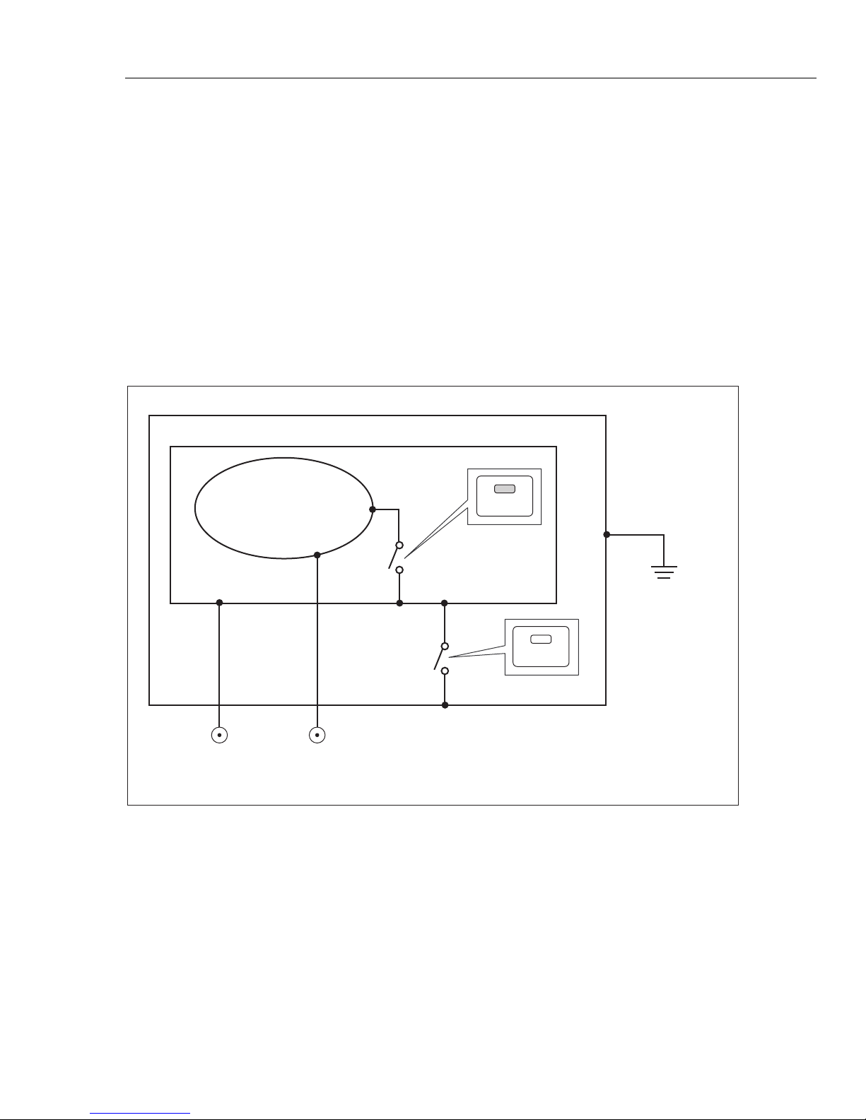
Front Panel Operation
How to Connect the Calibrator to a UUT 4
Recommended Cable and Connector Types
Warning
To prevent possible electrical shock, fire, or personal injury, do
not touch exposed metal on banana plugs, they can have
voltages that could cause death.
Cables to the calibrator are connected to the NORMAL and AUX terminals. To avoid
errors induced by thermal voltages (thermal emfs), use connectors and conductors made
of copper or materials that generate small thermal emfs when joined to copper. Avoid
using nickel-plated connectors. Optimum results can be obtained by using Fluke Model
5440A-7002 Low Thermal EMF Test Leads, which are constructed of well-insulated
copper wire and tellurium copper connectors. (See Chapter 9, “Accessories.”)
When to Use EARTH and EXGRD
Figure 4-1 shows the internal connections made by the Z and B keys.
Chassis ground
Internal guard shield
Earth
NORMAL LO
signal ground
EXGRD
Lit = open
Safety ground
through
ac line cord
EARTH
Not lit = open
GUARD
binding
post
NORMAL LO
binding
post
nn003f.eps
Figure 4-1. EARTH and EXGRD Internal Connections
The Calibrator front panel NORMAL LO terminal is normally isolated from earth
(chassis) ground. When it is desired to make a connection between the NORMAL LO
terminal and earth ground, press the Z key, lighting the key annunciator. When the
earth key is pressed, the NORMAL LO terminal is connected to earth ground through
approximately 30 Ω.
To avoid ground loops and noise you must have only one earth ground-to-LO terminal
connection in the system. Usually you make all signal ground connections at the UUT
and verify the Z annunciator is off. Generally, Z is on only for ac and dc volts
where the UUT is isolated from earth ground. There must, however, be a safety ground
for the Calibrator. See “Connecting to Line Power” in Chapter 2. When enabled by the
4-9
Page 86

5522A
Operators Manual
External Guard
Four-Wire versus Two-Wire Connections
sourced output, a softkey LOs appears, which allows you to tie or open an internal
connection between the NORMAL LO terminal and AUX LO terminal. When tied and
Z is on, then both LO terminals are tied to chassis ground.
The guard is an electrical shield, isolated from the chassis, that protects the analog
circuitry. The guard provides a low-impedance path for common-mode noise and ground
loop currents. The internal guard is connected to NORMAL LO through approximately
30 Ω. There is normally an internal connection between the guard and the NORMAL LO
terminal. By pressing the B key, you break this internal connection, which allows you
to connect a lead from the GUARD terminal to earth ground on another instrument in an
interconnected system. Use this external guard connection whenever you are testing a
UUT that has a grounded LO terminal. Remember to always maintain only one earth
ground tie point in a system.
Four-wire and two-wire connections refer to methods of connecting the Calibrator to the
UUT to cancel out test lead resistance to assure the highest precision of the calibration
output. Figures 4-2 through 4-4 illustrate the connection configurations for resistance;
Figures 4-5 and 4-6 illustrate connection configurations for capacitance. The external
sensing capability of the four- and two-wire compensated connections provides increased
precision for resistance values below 110 kΩ and capacitance values 110 nF and above.
Part of the setting up the calibrator output for resistance and capacitance includes
selections for four-wire compensation (COMP 4-wire), two-wire compensation (COMP
2-wire) and two-wire no compensation (COMP off). (See “Setting Resistance Output”
and “Setting Capacitance Output” later in this chapter.) Note that compensated
connections for capacitance are to compensate for lead and internal resistances, not for
lead and internal capacitances.
Four-Wire Connection
The four-wire connection is typical for calibrating laboratory measurement equipment.
Increased precision is provided for resistance values below 110 kΩ. For other values, the
lead resistances do not degrade the calibration and the Calibrator changes the
compensation to off (COMP off).
Two-Wire Compensation
The two-wire connection is typical for calibrating precision handheld Digital Multimeters
(DMMs) with a two-wire input. Increased precision is provided for resistance values
below 110 kΩ and capacitance values 110 nF and above. For other values, the Calibrator
changes the compensation to off (COMP off).
Compensation Off
Compensation off is a typical connection for calibrating handheld analog meters or
DMMs with a two-wire input. This connection is used for all values of resistance and
capacitance and is usually selected when the analog meter or DMM level of accuracy
does not require the additional precision. This is the default condition whenever an ohms
or capacitance output is made, following an output that was not ohms or capacitance.
Cable Connections Instructions
Table 4-1 indicates a figure reference for each type of connection between a UUT and the
Calibrator, referencing Figures 4-2 through 4-10.
When calibrating Resistance Temperature Detectors (RTDs) using the three-terminal
connection shown in Figure 4-9, be sure the test leads have identical resistances to cancel
any errors due to lead resistance. This can be accomplished, for example, by using three
identical test lead lengths and identical connector styles.
4-10
Page 87
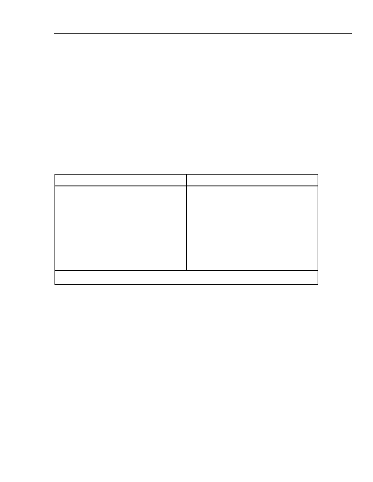
Front Panel Operation
How to Connect the Calibrator to a UUT 4
When calibrating thermocouples, it is especially important to use the correct hookup wire
and miniconnector between the Calibrator front panel TC terminal and the UUT. You
must use thermocouple wire and miniconnectors that match the type of thermocouple.
For example, if simulating a temperature output for a type K thermocouple, use type K
thermocouple wire and type K miniplugs for the hookup.
To connect the calibrator to a UUT, proceed as follows:
1. If the calibrator is turned on, press R to remove the output from the calibrator
terminals.
2. Make the connections to the UUT by selecting the appropriate figure from Table 4-1.
For capacitance outputs, null out stray capacitance by connecting the test leads to the
UUT, routing them (but not connecting) to the Calibrator on a non-conductive surface.
Null out the reading on the UUT using “rel,” “offset,” or “null,” whichever method
applies, and then connect the test leads to the Calibrator.
Table 4-1. UUT Connections
5522A Output Figure Reference
Resistance
Capacitance
DC Voltage
AC Voltage
DC Current
AC Current
RTD Simulation
Thermocouple Simulation
Note:
See the discussion under “Four-Wire versus Two-Wire Connections” above.
4-2 Resistance - four-wire compensated
4-3 Resistance - two-wire compensated
4-4 Resistance - compensation off
4-5 Capacitance - two-wire compensated
4-6 Capacitance - compensation off
4-7 DC Voltage/AC Voltage
4-7 DC Voltage/AC Voltage
4-8 DC Current/AC Current
4-8 DC Current/AC Current
4-9 Temperature (RTD)
4-10 Temperature (Thermocouple)
4-11
Page 88
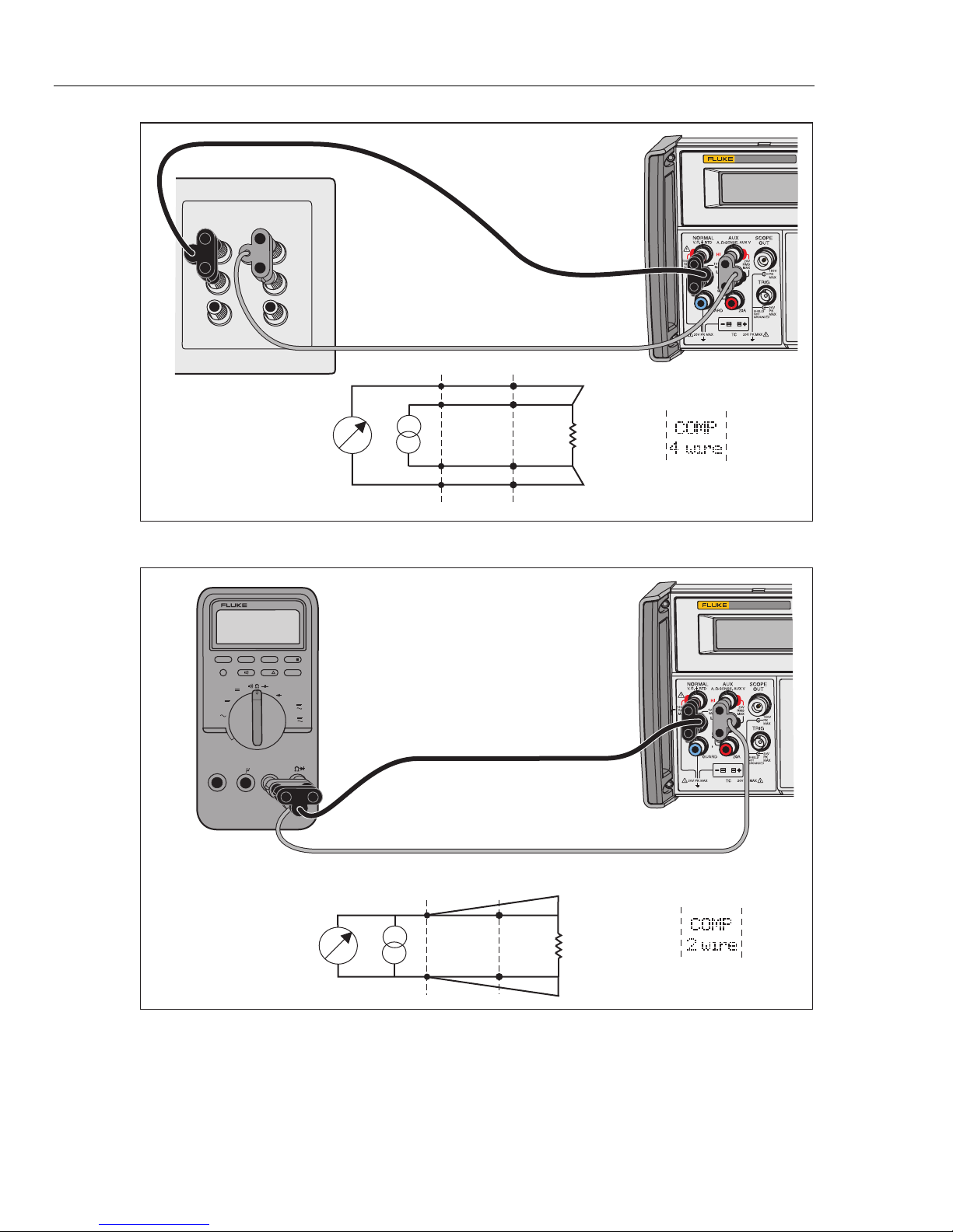
5522A
5522A
CALIBRATOR
Operators Manual
UUT
5522A
CALIBRATOR
HI
LO
A
INPUT
V
OFF
SENSE
4-WIRE
W
HI
LO
SENSE
SOURCE
UUT
5522A
SOURCE
SENSE
Figure 4-2. UUT Connection: Resistance (Four-Wire Compensation)
TRUE RMS MULTIMETER
87
RANGE HOLD
REL Hz
H
mA
A
A
m
MIN MAX
PEAK MIN MAX
mV
V
gjh014.eps
4-12
COM
V
UUT
5522A
mA A
A
Figure 4-3. UUT Connection: Resistance (Two-Wire Compensation)
gjh015.eps
Page 89
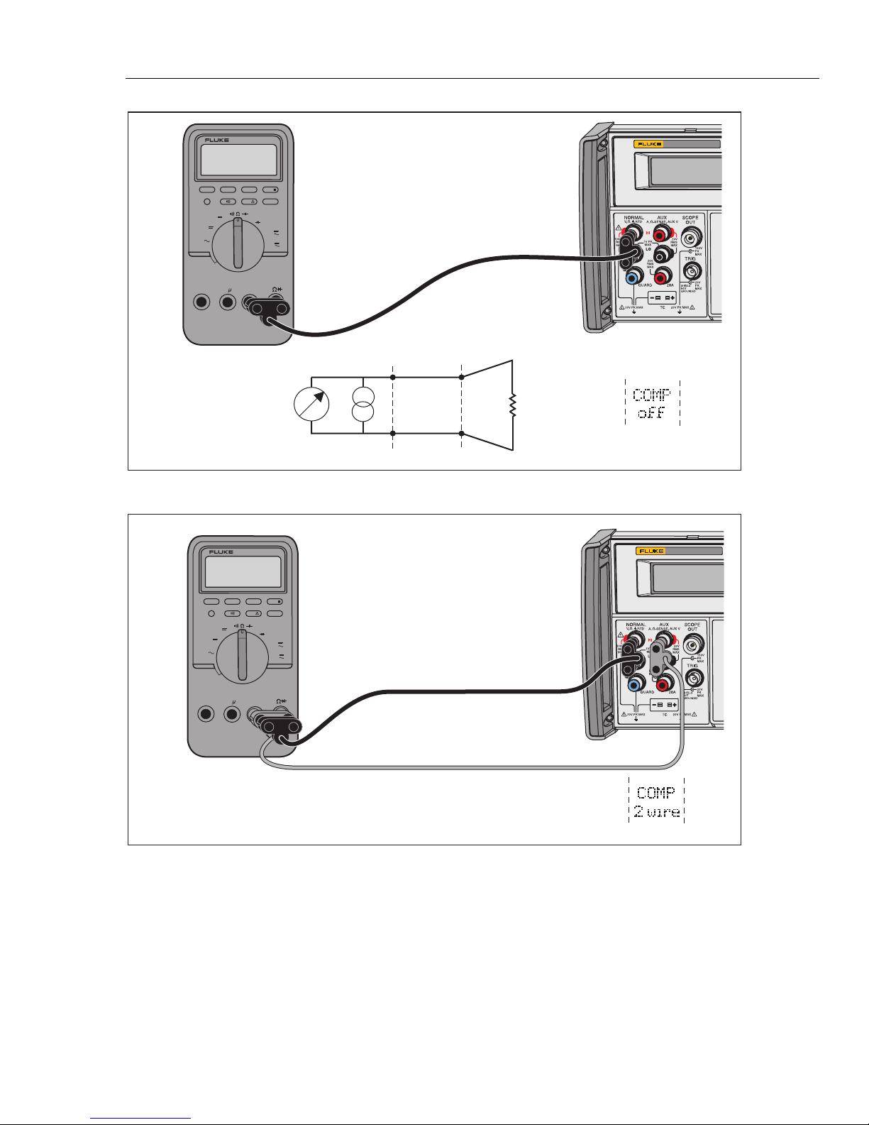
Front Panel Operation
How to Connect the Calibrator to a UUT 4
TRUE RMS MULTIMETER
87
5522A
CALIBRATOR
RANGE HOLD
REL Hz
COM
UUT
H
mA
A
A
m
V
5522A
gjh016.eps
MIN MAX
PEAK MIN MAX
mV
V
V
OFF
mA A
A
Figure 4-4. UUT Connection: Resistance (Compensation Off)
TRUE RMS MULTIMETER
87
5522A
CALIBRATOR
RANGE HOLD
REL Hz
COM
H
mA
A
m
A
V
MIN MAX
PEAK MIN MAX
mV
V
V
OFF
mA A
A
Figure 4-5. UUT Connection: Capacitance (Two-Wire Compensation)
gjh017.eps
4-13
Page 90
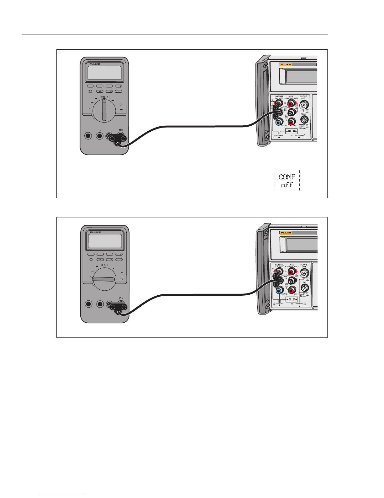
5522A
Operators Manual
TRUE RMS MULTIMETER
87
5522A
CALIBRATOR
RANGE HOLD
REL Hz
mA
COM
H
A
m
A
V
gjh018.eps
MIN MAX
PEAK MIN MAX
mV
V
V
OFF
mA A
A
Figure 4-6. UUT Connection: Capacitance (Compensation Off)
TRUE RMS MULTIMETER
87
RANGE HOLD
REL Hz
H
mA
A
A
m
MIN MAX
PEAK MIN MAX
mV
V
V
OFF
5522A
CALIBRATOR
4-14
COM
V
gjh019.eps
mA A
A
Figure 4-7. UUT Connection: DC Voltage/AC Voltage
Page 91
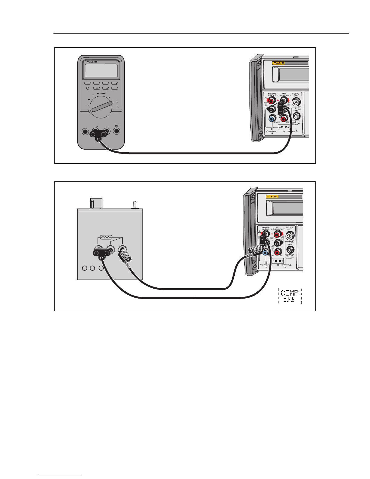
Front Panel Operation
How to Connect the Calibrator to a UUT 4
TRUE RMS MULTIMETER
87
5522A
CALIBRATOR
RANGE HOLD
REL Hz
COM
H
mA
A
A
m
V
MIN MAX
PEAK MIN MAX
mV
V
V
OFF
mA A
A
Figure 4-8. UUT Connection: DC Current/AC Current
CHART RECORDER INPUT
5522A
CALIBRATOR
gjh020.eps
Figure 4-9. UUT Connection: Temperature (RTD)
gjh021.eps
4-15
Page 92
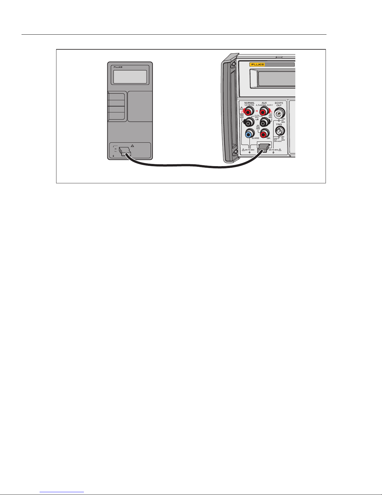
5522A
Operators Manual
CALIBRATOR
K/J THERMOMETER
51
ON/OFF
F/C
HOLD
OFFSET
60V
24V
MAX
!
5522A
Connection wiring must match thermocouple type, e.g., K, J, etc.
Figure 4-10. UUT Connection: Temperature (Thermocouple)
RMS Versus p-p Amplitude
The Calibrator ranges for sinusoidal ac functions are specified in rms (root-mean-square;
the effective value of the wave form). For example, 1.0 to 32.999 mV, 33 to 329.999 mV,
0.33 to 3.29999 V and so forth. The sine wave outputs are in rms, while the triangle
wave, square wave, and truncated sine wave outputs are in p-p. The relationship between
p-p and rms for the non-sine wave types are as follows:
• Square wave p-p x 0.5000000 = rms
• Triangle wave p-p x 0.2886751 = rms
• Truncated Sine wave p-p x 0.2165063 = rms
While the ac function ranges are directly compatible for sine waves, the rms content of
the other waveforms is less apparent. This characteristic leads to subtle calibrator range
changes. For example, if you enter a sine wave voltage of 6 V (rms assumed), the
selected range is 3.3 to 32.9999 V. If you then use the softkeys to change from a sine
wave to a triangle wave, for example, the display changes from 6 V rms to 6 V p-p. This
translates to 6 V p-p x 0.2886751 = 1.73205 V rms, and the range switches to 0.33 to
3.29999 V. The Output Display shows the range change because the sine wave voltage is
displayed as 6.0000, the resolution for the 3.3 to 32.9999 V range, while the triangle
wave is displayed as 6.00000, the resolution for the 0.33 to 3.29999 V range.
You need to know the active range to enter the correct values for voltage offset because
the maximum offsets are range specific. For example, the maximum peak signal for the
3.3 to 32.9999 V range is 55 V while the maximum peak signal for the 0.33 to 3.29999 V
range is 8 V. This means in the example above, the 6 V rms sine wave could have offsets
applied up to the maximum peak signal of 55 V because the active range is 3.3 to
32.9999 V, while the 6 V p-p triangle wave could have offsets applied up to the
maximum peak signal of 8 V because the active range is 0.93 to 9.29999 V. See
“Specifications” in Chapter 1 and “Entering a DC Offset” later in this chapter for more
information about dc offset voltages.
gjh022.eps
4-16
Page 93
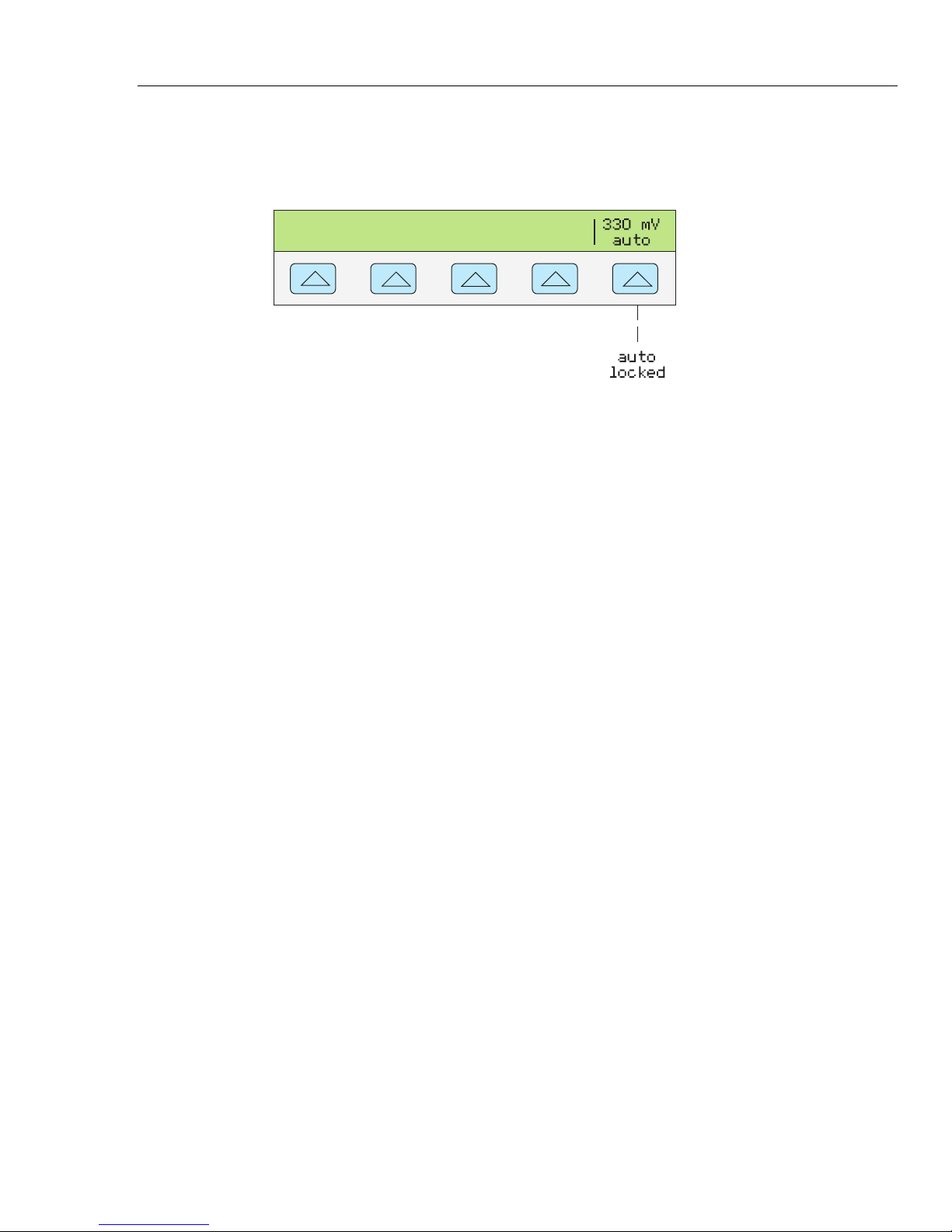
Front Panel Operation
Auto Range Versus Locked Range 4
Auto Range Versus Locked Range
A softkey is provided to toggle between the ranging method auto or locked. This feature
is available only for single-output dc volts and dc current outputs.
When auto is selected (the default setting), the calibrator automatically selects the range
that provides the best output resolution. When locked is selected, the calibrator locks the
selected range and will not change ranges when you are editing the output, or entering
new outputs. Values lower or higher than the locked range are not allowed. The locked
selection is usually made when you do not want range changes that may cause a small
perturbation in the output, e.g., when checking the linearity of a given multimeter range.
How to Set Output
Setting the calibrator output is similar to entering values into a calculator: press the keys
that represent the value you desire and then press a units key to identify which of the
volts, amps, hertz, etc. you want the value to represent. The control display indicates the
value and units you select as you type them into the calibrator. Once you are satisfied
with the value and units, press E. If the output display indicates STBY, press O
to output the selection. The display of a small “u” (unsettled) in the Output Display
indicates the calibrator is allowing for its internal circuitry to settle.
For example, to set the output to 10 V dc, press:
1 → 0 → V → E → O
To set the output to 20 V ac at 60 Hz press:
2 → 0 → V → 6 → 0 → H → E → O
nn063f.eps
To change the output to dc, press:
0→H→E or I→E
Step-by-step procedures are provided for each output function as follows:
• DC voltage
• AC voltage
• DC current
• AC current
• DC power
• AC power
• Dual DC voltage
• Dual AC voltage
•
Capacitance
• Temperature - RTD
• Temperature - Thermocouple
• Resistance
4-17
Page 94
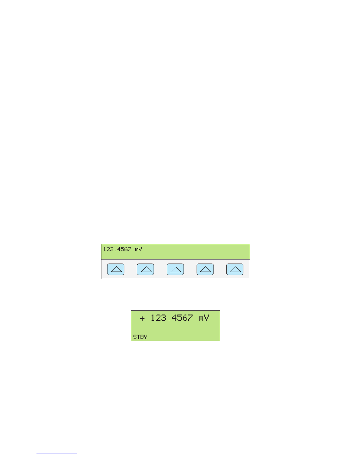
5522A
Operators Manual
How to Set DC Voltage Output
Complete the following procedure to set a dc voltage output at the front panel NORMAL
terminals. If you make an entry error, press Gto clear the display, then reenter the
value.
Caution
To prevent damage to the UUT, Verify the applied voltage to the
UUT does not exceed the rating of the UUT insulation and the
interconnecting wiring.
1. Press R to clear any output from the Calibrator.
2. Connect the UUT as described earlier in this chapter under “Connecting the
Calibrator to a UUT.”
3. Set the UUT to measure dc voltage on the desired range.
4. Press the numeric keys and decimal point key to enter the desired voltage output
(maximum seven numeric keys). For example, 123.4567.
Note
At voltage outputs of 100 volts and above (nominal), you may notice a
slight high-pitched sound. This is normal.
5. Press I to select the polarity of the voltage (default is +)
6. Press a multiplier key, if necessary. For example, press c.
7. Press V.
8. The Control Display now shows the amplitude of your entry. For example,
123.4567 mV (below).
nn071f.eps
9. Press E. The calibrator clears your entry from the Control Display and copies it
into the Output Display (below is typical).
nn072f.eps
10. Press O to activate the calibrator output.
A softkey label for range appears on the Control Display in the dc voltage function:
4-18
Page 95
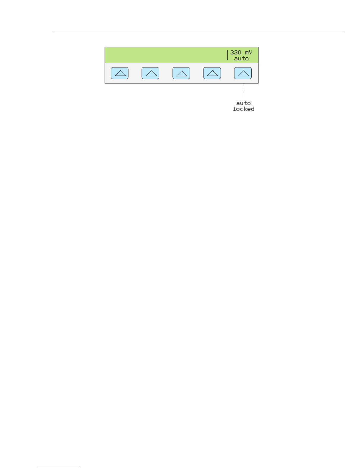
Front Panel Operation
How to Set Output 4
• Range (Operating Range) selects autorange (auto) or lock (locked) for the present
range. When auto (the default setting) is selected, the calibrator automatically selects
the range that provides the best output resolution. When locked is selected, the
calibrator will not change ranges when you are editing the output. The locked
selection is usually made when you do not want range changes that may cause a
small perturbation in the output, e.g., when checking the linearity of a given
multimeter range.
How to Set AC Voltage Output
You may select an ac voltage output in volts or as a power output in dBm, where dBm is
10 log(Pout/.001) , where Pout is expressed in watts. The output range is 1 mV to
1000 V. When selecting dBm outputs, the Calibrator calculates dBm at a selected
impedance level. Based on this, the formula is:
20 log(V) - 10 log(Impedance * .001) = dBm.
Complete the following procedure to set an ac voltage output at the front panel
NORMAL terminals. If you make an entry error, press G to clear the display, then
reenter the value.
To prevent damage to the UUT, verify the applied voltage to the
UUT does not exceed the rating of the UUT insulation and the
interconnection wiring.
Caution
nn063f.eps
1. Press R to clear any output from the Calibrator.
2. Connect the UUT as described earlier in this chapter under “Connecting the
Calibrator to a UUT.”
3. Set the UUT to measure ac voltage on the desired range.
Output in volts Press the numeric keys and decimal point key to enter the desired voltage
output (maximum six numeric keys). For example, 2.44949.
Output in dBm Press the numeric keys and decimal point key to enter the desired power
output (maximum six numeric keys). For example, 10.0000. For a power output less than
1 mW (negative dBm values), press I to append the numeric entry with the negative
(−) symbol.
When you press the dBm key, the right most softkey becomes active. This allows the
dBm value and output impedance to be entered as a unit.
When output is entered in dBm, the Control Display appears as follows:
4-19
Page 96
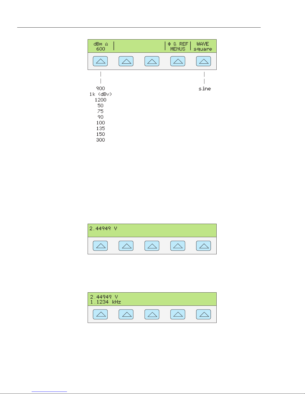
5522A
Operators Manual
nn227f.eps
Note
At voltage outputs of 100 V and above (nominal), you may notice a slight
high-pitched sound. This is normal.
1. Press a multiplier key, if necessary. For example, press c.
2. Output in volts. Press V.
Output in dBm. Press b V. Select an impedance for dBm from a list on the
Control Display using the rightmost softkey.
3. The Control Display now shows the amplitude of your entry. For example,
2.44949 V (below).
nn073f.eps
4. Press the numeric keys and decimal point key to enter the desired frequency output
(maximum five numeric keys). Press a multiplier key, if necessary. For example,
press the kilo multiplier key K. The press the H key. For example, 1.1234 kHz
(below).
5. Press E. The calibrator clears your entry from the Control Display and copies it
into the Output Display (below is typical).
4-20
nn074f.eps
Page 97
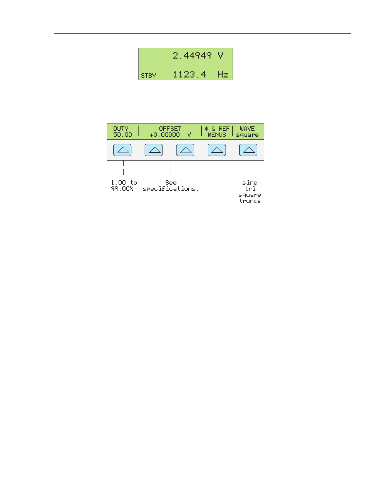
Front Panel Operation
How to Set Output 4
nn075f.eps
6. Press O to activate the calibrator output.
Several softkey labels appear on the Control Display in the ac voltage function,
depending on which waveform is selected: DUTY, OFFSET and WAVE.
nn076f.eps
• DUTY (Duty Cycle) When the square wave is selected, DUTY appears, allowing
you to modify the duty cycle of the square wave. The range is 1.00 to 99.00 %. The
default is 50.00 %. The duty cycle must be 50.00 % if you want to enter an OFFSET
(see below).
• OFFSET (Voltage Offset) appears when the desired output is less than 33 V (sine
waves), 65 V (square waves) or 93 V (triangle waves and truncated sine waves). This
softkey allows you to add a positive or negative dc offset voltage to the ac output
signal. See “Entering a DC Offset” later in this chapter for more information. When a
voltage output is expressed in dBm, voltage offset is not available. You can enter an
offset for a square wave output only when the duty cycle is 50.00 % (see DUTY
above).
• Φ & REF MENUS (Phase Difference and 10 MHz reference source.) Selects the
phase difference between the NORMAL and AUX outputs, selects internal or
external 10 MHz reference, and sets the phase difference between an external master
Calibrator (using 10 MHz IN/OUT) and the NORMAL output. See “Adjusting the
Phase” and “Synchronizing the Calibrator using 10 MHz IN/OUT” later in this
chapter.
• WAVE (Waveform) allows you to select one of four different types of waveforms:
sine wave, triangle wave, square wave, and truncated sine wave. (See “Waveform
Types” later in this chapter for more information). Whenever a non-sinusoidal
waveform is selected, the Output Display shows Pp (p-p). Only sine wave is allowed
for output in dBm.
4-21
Page 98
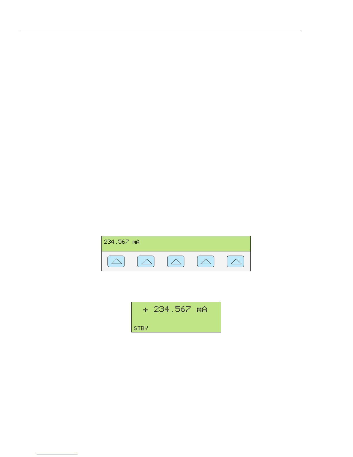
5522A
Operators Manual
How to Set DC Current Output
Complete the following procedure to set a dc current output between AUX HI and LO or
AUX 20A and LO, depending on the current level selected. Current greater than ±3 A is
sourced between the AUX 20A and LO terminals. If you make an entry error, press G
to clear the display, then reenter the value.
Note
See Figure 1-4 in Chapter 1 for a chart that shows duration or duty cycle
limitations for current greater than 11 A. If the duration or duty cycle is
exceeded, the Calibrator will shut down abruptly. After a cool-off period,
the Calibrator will work normally.
1. Press R to clear any output from the calibrator.
2. Connect the UUT as described earlier in this chapter under “How to Connect the
Calibrator to a UUT.”
3. Set the UUT to measure dc current on the desired range.
4. Press the numeric keys and decimal point key to enter the desired current output
(maximum six numeric keys). For example, 234.567.
5. Press I to select the polarity of the current (default is +).
6. Press a multiplier key, if necessary. For example, press c.
7. Press A.
8. The Control Display now shows the amplitude of your entry. For example,
234.567 mA.
nn077f.eps
9. Press E. The calibrator clears your entry from the Control Display and copies it
into the Output Display (below is typical).
nn078f.eps
10. Press O to activate the calibrator output.
A range softkey appears on the Control Display in the dc current function (operating
range). This selects autorange (auto) or lock (locked) for the present range. When auto
(the default setting) is selected, the calibrator automatically selects the range that
provides the best output resolution. When locked is selected, the calibrator will not
change ranges when you are editing the output. The locked selection is usually made
when you do not want range changes that may cause a small perturbation in the output,
e.g., when checking the linearity of a given multimeter range.
Another softkey appears: OUTPUT. When you select 20 A for this parameter, or you
select a current above 3 A, the calibrator switches to standby, and you must change the
test lead to the 20A terminal and press O to activate the output.
4-22
Page 99
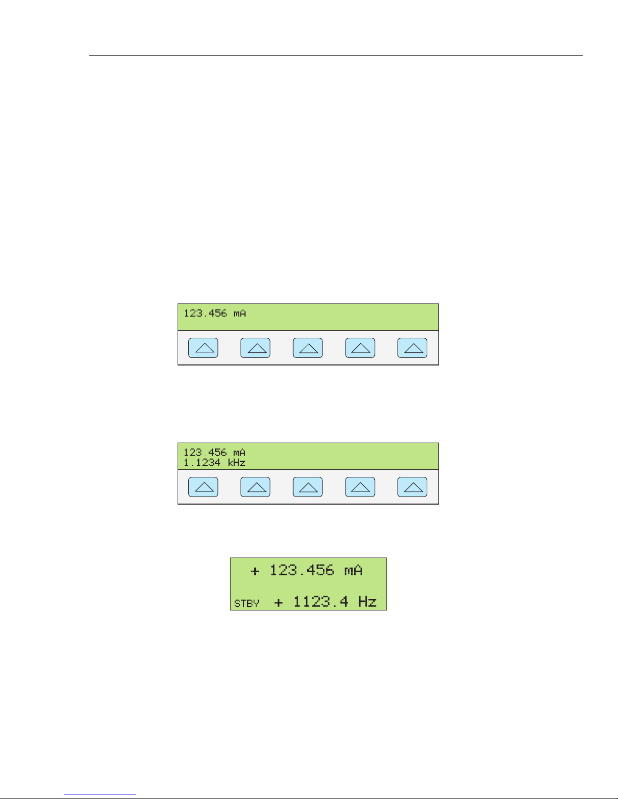
Front Panel Operation
How to Set Output 4
How to Set AC Current Output
Complete the following procedure to set an ac current output at the AUX or 20A
terminals. If you make an entry error, press G to clear the display, then reenter the
value.
1. Press R to clear any output from the Calibrator,
2. Connect the UUT as described earlier in this chapter under “Connecting the
Calibrator to a UUT.”
3. Set the UUT to measure ac current on the desired range.
4. Press the numeric keys and decimal point key to enter the desired current output
(maximum six numeric keys). For example, 123.456.
5. Press a multiplier key, if necessary. For example, press c.
6. Press A.
7. The Control Display now shows the amplitude of your entry. For example,
123.456 mA (below).
nn079f.eps
8. Press the numeric keys and decimal point key to enter the desired frequency output
(maximum five numeric keys). Press a multiplier key, if necessary. For example,
press the kilo multiplier key K. Then press the H key. For example,
1.1234 kHz (below).
nn080f.eps
9. Press E. The calibrator clears your entry from the Control Display and copies it
into the Output Display (below is typical).
nn081f.eps
10. Press O to activate the calibrator output.
4-23
Page 100
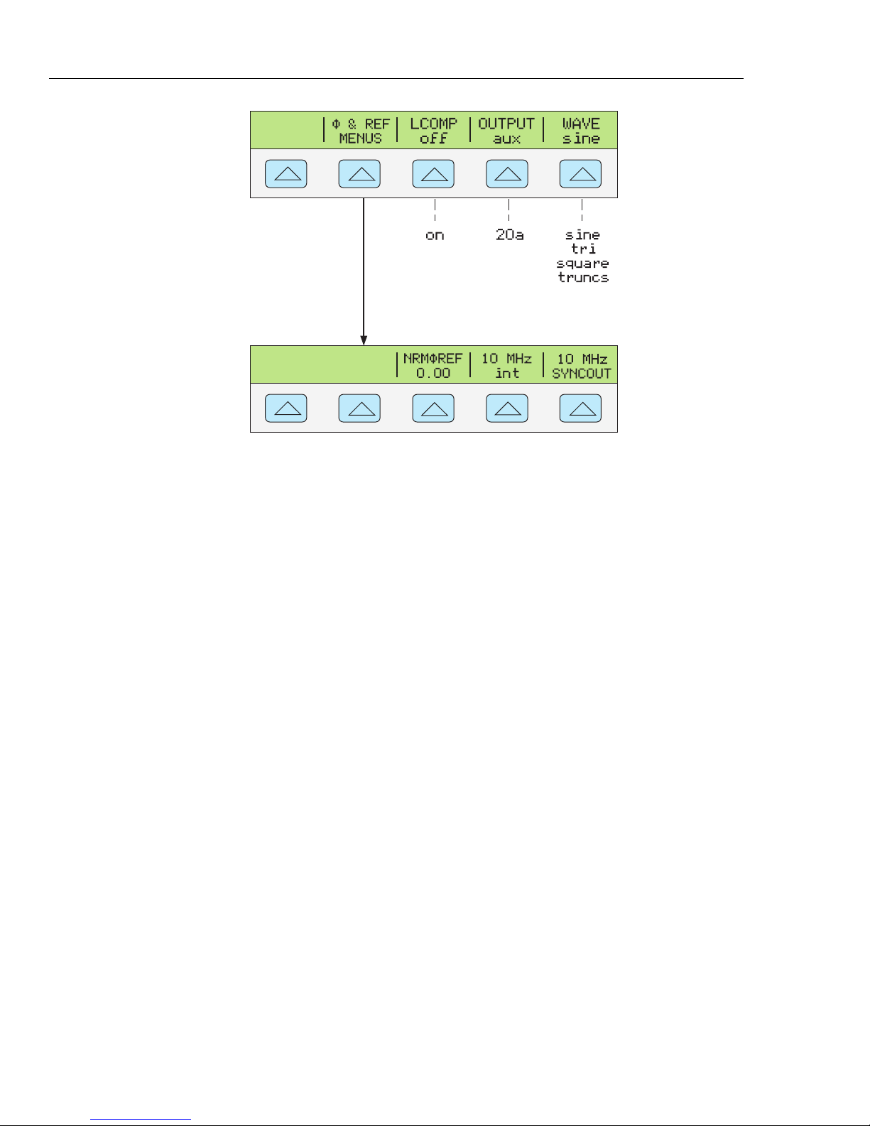
5522A
Operators Manual
• Φ & REF MENUS (Phase Difference and 10 MHz reference source.) Selects the
phase difference between the NORMAL and AUX outputs, selects internal or
external 10 MHz reference, and sets the phase difference between an external master
5522A (using 10 MHz IN/OUT) and the NORMAL output. See “Adjusting the
Phase” and “Synchronizing the Calibrator using 10 MHz IN/OUT” later in this
chapter.
• LCOMP turns inductive compensation on and off. Inductive compensation is
available for frequencies up to 1 kHz at outputs up to 239.999 mA, and for
frequencies up to 440 Hz above 239.999 mA.
• OUTPUT shows whether the output is on the AUX or 20A terminals. Outputs 3A or
above are always on the 20A terminals.
• WAVE (waveform) selects one of four different types of waveforms: sine wave,
triangle wave, square wave, and truncated sine wave. (See “Waveform Types” later
in this chapter for more information). Whenever a non-sinusoidal waveform is
selected, the Output Display will convert the RMS reading to p-p (PP).
How to Set DC Power Output
Tie the terminals NORMAL LO and AUX LO together at the UUT or at the
Calibrator, via the “LO”s softkey selection “tied.”
Note
nn321f.eps
The calibrator produces a dc power output by sourcing a dc voltage on the NORMAL
outputs and a dc current on the AUX outputs. Complete the following procedure to set a
dc power output. If you make an entry error, press Gone or more times to clear the
display, then reenter the value.
To prevent damage to the UUT, verify the applied voltage to the
UUT does not exceed the rating of the UUT insulation and the
interconnecting wiring.
1. Press R to clear any output from the Calibrator.
2. Connect the UUT as described earlier in this chapter under “Connecting the
4-24
Caution
 Loading...