

Page 1

Fluke 54100 Video Signal Generator
Fluke 54200 TV Signal Generator
®
The purest signals, the widest choice
Page 2

Two models
There are two compact models in the
series. The Fluke 54100 Video Signal
Generator is the obvious choice for
testing video circuitry. The Fluke 54200
TV Signal Generator offers additional
sound test signals and a highly stable
RF output, making it ideal for complete
testing of TV sets, VCRs or other related
equipment. Both models offer selectable
TV standards (PAL, NTSC, SECAM), text
functions and a choice of signal outputs.
You can choose from a number of readily
available pre-configurations, or select an
instrument that precisely matches your
testing requirements, specifying options
from a range of stereo sound, data
services and interface functions. You’ll
find all details on the separate option
and ordering information inserts.
All applications
The digitally generated test signals of the
Fluke 54000 Series comply with the
recommendations of the CCIR, EBU, FCC,
ITU and EIA standards for analog television. This versatility, combined with
the high signal quality (stability and
purity) makes them ideal for testing TV
receivers, VCRs, camcorders, observation
systems and set-top decoder boxes, and
also for checking the performance of
individual sub-assemblies or components
used in these products.
Easy to Use
These generators are excellent examples
of Fluke’s reputation for easy-to-use
instruments:
• Select the main functions directly on
the front-panel keyboard. More
advanced functions can be accessed
using soft keys and the large LCD
(Liquid Crystal Display) with its familiar
graphical interface.
• Accurately set luminance and chrominance amplitudes with the up and
down keys or the numerical keyboard.
• Store up to 99 different test situation
settings for later instantaneous recall.
• Finally, to make it even more convenient, a number of country specific
settings have been pre-programmed.
Just think of the time this will save you.
Just what you need
Whether you work in development,
production, quality assurance, installation, maintenance or repair, there’s
always a model to suit your needs,
thanks to the standard capabilities of
these instruments, together with the
range of options. Their ease of use and
compact size makes them ideal, both for
personal use on the bench and for use
by a group of engineers. Need to make
automated measurements? It’s simple
with the Fluke 54000 Series, as you can
remotely control all functions via the
optional combined IEEE-488 (GPIB) and
RS-232 interface.
It’s all you need for accurate multi-
standard video and TV signal testing
Meet the 54000 Series from Fluke, a range of easy to use instruments to test TVs, VCRs, set top
boxes and other video equipment. According to any video standard. And with today’s widest choice
of highly accurate signals.
Covers all video standards
• Meets CCIR, EBU, FCC, ITU and EIA
analog television standards
• More than 500 digitally generated
test patterns for PAL, NTSC and
SECAM, including 16:9 and 4:3
aspect ratios
• High precision setting and indication
for video, chrominance and RF
amplitudes
• Very stable RF terrestrial output with
internal/external modulation, group
delay pre-correction and a level up to
100 mV
®
Page 3

Multi or single standard
The Fluke 54100 Video Signal Generator
and the Fluke 54200 TV Signal
Generator are available with PAL, NTSC
and/or SECAM video standard options.
You can select any combination of these
standards to create a single, double or
triple standard unit. The appropriate sub
standards (system B, D, G, I, K, K1, L, M or
N) are enabled automatically.
Wide range of patterns
The Fluke 54000 Series are today’s most
versatile generators. On all models you
will find the test patterns and capabilities
you’ll need to test and align the total
video signal path. There are over 500
test patterns – for calibrating geometry
(in 4:3 and 16:9 aspect ratios), synchronization, focusing, static and dynamic
convergence. You’ll find signals for
checking bandwidth, interference (such
as cross-color), amplitude response,
tracking and clipping. As well as for color
reproduction, cut-off setting, high-voltage
stability, analog-to-digital conversion,
and much more. And your test results
will always be reliable, as all test
patterns are digitally generated to ensure
high stability and precise timing.
Stable RF output (Fluke 54200 only)
You need to do tuner and IF tests? The
terrestrial output on the Fluke 54200 TV
Signal Generator is just what you need.
Its highly stable signal covers the entire
RF frequency range from 32 to 900 MHz.
And you can set the frequency directly
with 50 kHz resolution. For fast and
precise reference, you can enter the
amplitude either in mV or dBµV and the
maximum output level is as high as
100 mV for the entire bandwidth.
Group delay pre-correction, also known
as group delay filtering, allows you to
test applications that need accurate
luminance and chrominance timing.
Page 4

Technical Specifications
OUTPUTS
CVBS VIDEO
Voltage (Vpp in 75Ω): 1V (nominal setting)
Setting range: 0 to 1.5V
Tolerance: 5%, 2% for nominal setting at
reference temperature
Resolution: 10 mV
Impedance: 75Ω
Polarity: Positive, negative
Coupling: DC
CVBS SYNC, LINE SYNC and
FIELD SYNCHRONISATION
Voltage (Vpp in 75Ω): 2V
Tolerance: 0.3V
Impedance: 75Ω
Polarity: Negative
Coupling: DC
EURO AV CONTROL VOLTAGES
Aspect Ratio: Automatically or off
Fast Blanking: Automatically or off
TERRESTRIAL RF CARRI ER (54200 only)
Frequency: 32 to 900 MHz
Tolerance: 10 kHz
Resolution: 50 kHz
Spectral purity: ≤ -60 dBc inside actual
TV channel
≤ -30 dBc outside actual
TV channel
Voltage (Vrms in 75Ω): 100 mV for high range
10 mV for low range
Attenuation: 0 to 80 dB for high range
0 to 60 dB for low range
Readout: mV, dBµV
Resolution: 0.01 mV for voltage ≤ 10 m V
0.1 mV for voltage > 10 mV
1 dB for dBµV indication
Tolerance: 3 dB
Flatness: ≤ 2 dB for 32 to 900 MHz
Impedance: 75Ω
Modulation: Double sideband AM
Internal, external
Group delay: 2 different types (or off)
INPUTS
VIDEO IN (54200 only)
Voltage (Vpp): 1V (nominal)
Impedance: 75Ω
Polarity: Positive
Coupling: DC
VIDEO
SYNCHRONISATION
Reference: CCIR Rep. 624-4, 1990
ANSI/ SMPTE 170M-1994
System: 625 lines (50 Hz)
525 lines (59.94 Hz)
Line frequency: 15.625 kHz for 625 line system
15.734265 kHz for 525 line system
Tolerance: 3 ppm for +5 to + 45 °C
1 ppm at reference temperature
Aging: ≤ 2 ppm per year
Level: -43% for 625 line system
-40 IRE for 525 line system
Tolerance: 3% for 625 line system
3 IRE for 525 line system
LUMINANCE
Reference: CCIR Rep. 624-4, 1990
ANSI/ SMPTE 170M-1994
Blanking level: 0% (0 IRE)
Black level: 0% for 625 line system
+7.5 IRE for 525 line system
White level: 100% (100 IRE)
Tolerance: 2% for 625 line system
2 IRE for 525 line system
CHROMINANCE
Reference: CCIR Rep. 624-4, 1990
ANSI/SMPTE 170M-1994
System: PAL B, D, G, I, K, M, N
NTSC M
NTSC with 4.433619 MHz
SECAM B, D, G, K, K1, L
Carrier frequency: 4.433619 MHz for PAL B, D,
G, I, K and NTSC 4.43
3.575611 MHz for PAL M
3.582056 MHz for PAL N
3.579545 MHz for NTSC M
4.406250 and
4.250000 MHz for SECAM
Tolerance: 3 ppm for +5 to +45 °C
1 ppm at reference
temperature
Aging: ≤ 2 ppm per year
Phase tolerance
(PAL/NTSC): 2°, 1° at reference temperature
Level: 100% (nominal setting)
Setting range: 0% to 150%
Resolution: 1%
Values stated without tolerances are typical values
Fluke 54100 Video Signal Generator
Fluke 54200 TV Signal Generator
®
Page 5

PATTERNS
Reference: ITU Rec. 471-1/1994 and SMPTE EG27-
1994 for color bar
SMPTE EG1-1990 for SMPTE color bar
CCIR Rec. 473-5, 1990 and
CCIR Rec. R26-1981 for IRS 17
CCIR Rec. 473-5, 1990 for multi burst
CCIR Rep. 1221 for PLUGE
Aspect ratio: 4:3, 16:9
Circle: 4 additional circles in 16:9 mode
Center cross: With border castellations (overscan in-
dication selectable between 2% or 3%)
White: 0, 5, 15 to 100% (5% steps) for
625 line system
7.5, 15 to 100 IRE (5 IRE steps) for
525 line system
Purity: Red, green, blue, cyan, magenta, yellow,
white, black (100/0/75/0 for 625 line
system and 100/7.5/75/7.5 for 525 line
system)
Dots: 17x13 dots in 4:3 mode, 23x13 dots
in 16:9 mode
With center indication
Crosshatch: 18x14 lines in 4:3 mode, 24x14 lines in
16:9 mode
With center and top/left
indication (selectable)
Checkerboard: 12x9 squares in 4:3 mode, 16x9 squares
in 16:9 mode
PLUGE: -1.6, 0, 1.6, 100% for 625 line system
4.8, 7.5, 10.7, 100 IRE for 525 line system
Grey scale: 10 steps linear staircase
VCR: VCR test (2 types)
Resolution test (2 types)
Writing current
Multi burst: 0.5, 1.0, 2.0, 4.0, 4.8, 5.8 MHz for 625
line system
0.5, 1.0, 2.0, 3.0, 3.58, 4.2 MHz for 525
line system
With time intervals
Digital scan: ADC check (2 types)
Moving block
Progressive scan check (3 types)
Color bar: 75/0/75/0, 100/0/75/0, 75/0/100/25,
100/0/100/25 for 625 line system
75/7.5/75/7.5, 100/7.5/75/7.5 for 525 line
system
SMPTE color bar
Horizontal color bar (75/0/75/0 for 625
line system and 75/7.5/75/7.5 for 525 line
system)
DEM: Demodulator test (2 types)
Color temperature: 3 different sizes with adjustable levels for
center and border
Diverse: EHT test (Reference rectangle with
switching white/black window)
IRS 17 (Available as full field test pattern
as well as reference line 17, only for 625
line system)
Pattern combination: Circle with every other pattern (except
progressive scan) or combination
Center cross / crosshatch / dots / purity
Grey scale / white / multi burst / color bar
Technical Specifications (cont.)
VCR patterns
Digital scan patterns
Color bar patterns
IRS 17 pattern
Pattern combinations
Demodulator patterns
®
Page 6

®
Push-button mono sound test signals
To help you test the mono sound capabilities
of TV receivers and VCRs, standard audio test
signals are available with every selected
stereo sound option on the Fluke 54200 TV
Signal Generator. Several tone frequencies
allow you to test the complete path for audio
sound. Operation is simple, as you can select
the main sound test functions directly on the
front panel. More specific settings, such as
sound carrier level, frequency and preemphasis, can be modified via soft keys.
Multi-system analog stereo
The analog stereo option supports various
two-carrier analog stereo systems, including
BG, A2 and Mk stereo. The B and G stereo
systems are often referred to as German or
'Zweiton' stereo. A2 stereo is used in
combination with both SECAM and PAL
television standards. It is transmitted in
several eastern European countries and is also
known as PAL/SECAM system DK stereo.
Mk is a two-carrier NTSC stereo sound system
and is used in Korea. For all these two-carrier
stereo systems, the analog stereo option
generates the appropriate pilots and delivers
tone frequencies in mono, stereo or dual
mode. Tone frequencies of 0.5, 1.0 and
3.0 kHz are included and for system M and N
the lowest frequency is 0.3 kHz. Using these
analog sound functions, you can test a variety
of audio parameters, such as channel
separation, signal to noise and harmonic
distortion. All signals are generated digitally,
to ensure high signal stability and purity.
General sound settings
Sound system selection
•
Analog stereo containing German,
Korean and DK stereo
•
NICAM stereo
•
BTSC sound test signals (MTS Stereo plus SAP)
That sounds just right....
Page 7
®
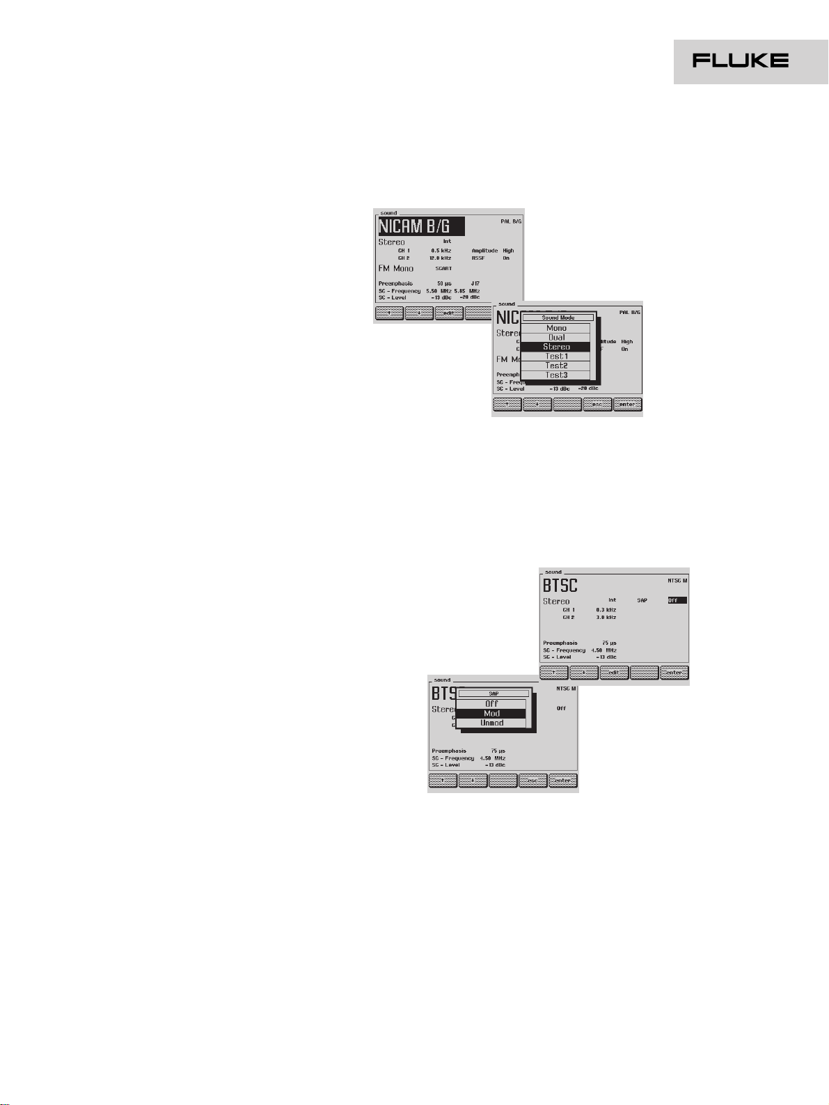
Versatile NICAM digital sound
If you need digital sound capabilities, you
should specify this option. NICAM, also
available in SECAM, is compatible with the
existing PAL terrestrial TV and cable TV
standards, and adds two high-quality digital
sound channels. Suitable TV sets can receive
two mono channels (this is called dual
channel) for simultaneous translation of
foreign-language programs, stereo signals or
transparent transmission of data. The option
provides mono, stereo and dual tone modes to
check the digital sound performance. For
channel 1, tone frequencies of 0.5, 1.0, 1.5 and
3.0 kHz are available, while you can modulate
channel 2 with a signal frequency of 1.0, 1.5,
3.0 and 12 kHz. Both digital sound channels
have selectable low- or high-amplitude signals
to test the NICAM expander of the TV receiver.
You can check the operation of the QPSK
demodulator and NICAM decoder with three
special test signals. You can also use these to
perform a level adjustment or measurement.
A high/low selectable RSSF (Reserve Sound
Switching Flag) indicates that the analog
(mono) and digital sound carriers are
transmitting different information, or that there
are errors in the digital transmission.
BTSC sound (MTS Stereo plus SAP)
In combination with NTSC and PAL TV
standards, this sound option generates BTSC
sound signals or Multi channel Television
Sound (MTS). Apart from mono and stereo
sound, a Second Audio Program (SAP) is also
available. You can select various test tone
frequency (0.3, 1.0 and 3.0 kHz) and mode
combinations, as well as special test signals.
These special test signals give you an easy
functional test for channel separation, signal to
noise ratio, level gaining and harmonic
distortion of the stereo and SAP decoders.
All sound signals are digitally generated which
ensures high stability, and they are available
both at the RF output or, via baseband
processing, at the precision MPX output.
NICAM modes
SAP modulation enabling
Page 8

Technical specifications
®
OUTPUTS
SOUND CARRIER
Voltage (Vpp in 50Ω):142 mV for mono carrier and
system B, G
200 mV for mono carrier and
system D, I, K, K1, L, M, N
63.2 mV for stereo and NICAM
(system B, D, G, I, K) carrier
28.3 mV for NICAM (system L)
carrier
Setting range: 112.5 to 356 mV for mono carrier
28.3 mV, 35.6 mV, 63.2 mV for
stereo and NICAM carrier
Tolerance: 2 dB
Resolution: 1 dB
Impedance: 50Ω
Connector: BNC rear
AUDIO and EURO AV
Voltage (Vrms in
open circuit): 500 mV
Tolerance: 5%
Impedance: 600Ω
Connector: Cinch rear, EURO AV rear
BTSC MPX and FM STEREO PILOT
Voltage (Vrms in
open circuit): 550 mV
Tolerance: 5%
Impedance: 600Ω
Connector: BNC rear
NICAM DATA and NICAM CLOCK
Frequency: 728 kHz
Tolerance: 3 ppm for +5 to +45°C
1 ppm at reference temperature
Aging: ≤ 2 ppm per year
Voltage (Vpp in 50Ω):1V
Tolerance: 10%
Impedance: 50Ω
Connector: BNC rear
INPUTS
AUDIO, EURO AV and MTS
Voltage (Vrms): 500 mV (nominal)
Impedance: 0.1 MΩ
Connector: Cinch rear, EURO AV rear, BNC
rear
MONO
SOUND CARRIER
Frequency: 4.5 MHz for system M, N
5.5 MHz for system B, G
6.0 MHz for system I
6.5 MHz for system D, K, K1, L
Tolerance: 3 ppm for +5 to +45°C
1 ppm at reference temperature
Aging: ≤ 2 ppm per year
Level: -13 dBc for system B, D, G, K, K1
-10 dBc for system I, L, M, N
Setting range: -5 to -15 dBc
Tolerance: 2 dB at reference temperature
Resolution: 1 dB
MODULATION
Frequency: 0.5, 1.0, 3.0 kHz for system B, D,
G, I, K, K1, L
0.3, 1.0, 3.0 kHz for system M, N
Type: FM for system B, D, G, I, K, K1, M,
N
AM for system L
Deviation: 27 kHz for system B, D, G, I, K, K1
13.5 kHz for system M, N
Tolerance: 5%
Pre-emphasis: 50 µs for system B, D, G, I, K, K1
75 µs for system M, N
Modulation depth: 54% for system L
STEREO
SOUND CARRIER 1
Data: As Mono
SOUND CARRIER 2
Frequency: 5.7421875 MHz for system B, G
6.2578125 MHz for system D, K
(A2)
4.724 MHz for system Mk
Tolerance: 3 ppm for +5 to +45°C
1 ppm at reference temperature
Aging: ≤ 2 ppm per year
Level: -20 dBc
Setting range: -20, -25, -27 dBc
Tolerance: 3 dB at reference temperature
MODULATION
Frequency: 0.5, 1.0, 3.0 kHz for system B, D,
G, K
0.3, 1.0, 3.0 kHz for system Mk
Type: FM
Deviation: 27 kHz for system B, D, G, K
13.5 kHz for system Mk
Tolerance: 5%
Pre-emphasis: 50 µs for system B, D, G, K
75 µs for system Mk
Page 9

Technical specifications (cont.)
®
IDENTIFICATION
Reference: CCIR Rec. 707
Frequency: fH/ 133 for stereo and system B,
D, G, K
fH/ 105 for stereo and system Mk
fH/ 57 for dual
Tolerance: 3 ppm for +5 to +45°C
1 ppm at reference temperature
Aging: ≤ 2 ppm per year
Type: AM
Modulation depth: 50%
Tolerance: 5%
NICAM STEREO
SOUND CARRIER 1
Data: As Mono
SOUND CARRIER 2
Frequency: 5.85 MHz for system B, D, G, K, L
6.875 MHz for system D, K
6.552 MHz for system I
Tolerance: 3 ppm for +5 to +45°C
1 ppm at reference temperature
Aging: ≤ 2 ppm per year
Level: -20 dBc for system B, D, G, I, K
-27 dBc for system L
Setting range: -20, -25, -27 dBc
Tolerance: 3 dB at reference temperature
MODULATION
Reference: NICAM-728
CCITT Rec J17
Frequency: 0.5, 1.0, 1.5, 3.0 kHz for channel 1
1.0, 1.5, 3.0, 12 kHz for channel 2
Demodulator pattern
Decoder pattern
Unmodulated carrier
Type: QPSK
Mode: Mono, Dual, Stereo, Test
Bit-rate: 728 kbits/s
Tolerance: 3 ppm for +5 to +45°C
1 ppm at reference temperature
Aging: ≤ 2 ppm per year
Level: High, low
RSSF: On, off
BTSC STEREO
SOUND CARRIER
Frequency: 4.5 MHz for system M, N
Tolerance: 3 ppm for +5 to +45°C
1 ppm at reference temperature
Aging: ≤ 2 ppm per year
Level: -10 dBc
Setting range -5 to -15 dBc
Tolerance: 2 dB at reference temperature
Resolution: 1 dB
MODULATION
Frequency: 0.3, 1.0, 3.0 kHz for channel 1
1.0, 3.0 kHz for channel 2 (3.1
and 8.0 kHz in Test modes)
5.0 kHz for SAP (0.3 and 1.0 kHz
in Test modes)
Type: FM with BTSC base band
Base band: Main channel
Identification pilot
Stereo sub channel
SAP sub channel
Base band type: FM modulated (BTSC compressed)
for stereo sub channel
AM modulated with suppressed
carrier (BTSC compressed) for SAP
subchannel
Mode: Mono, stereo, SAP
Tolerance: 5%
Pre-emphasis: 75 µs
IDENTIFICATION
Frequency: f
H
Tolerance: 3 ppm for +5 to +45°C
1 ppm at reference temperature
Aging: ≤ 2 ppm per year
Fluke Corporation
P.O. Box 9090, Everett, WA 98206
Fluke Europe B.V.
P.O. Box 1186,
5602 BD Eindhoven,
The Netherlands
For more information call:
In the U.S.A.: (800) 443-5853
or Fax: (425) 356-5116
In Europe/M-East:
+31 (0)40 2 678 200
or Fax: +31 (0)40 2 678 222
In Canada: (905) 890-7600
or Fax: (905) 890-6866
From other countries:
+1(425) 356-5500
or Fax: +1 (425) 356-5116
Web access: http://www.fluke.com
©Copyright 1998 Fluke Corporation.
All rights reserved.
Page 10
®
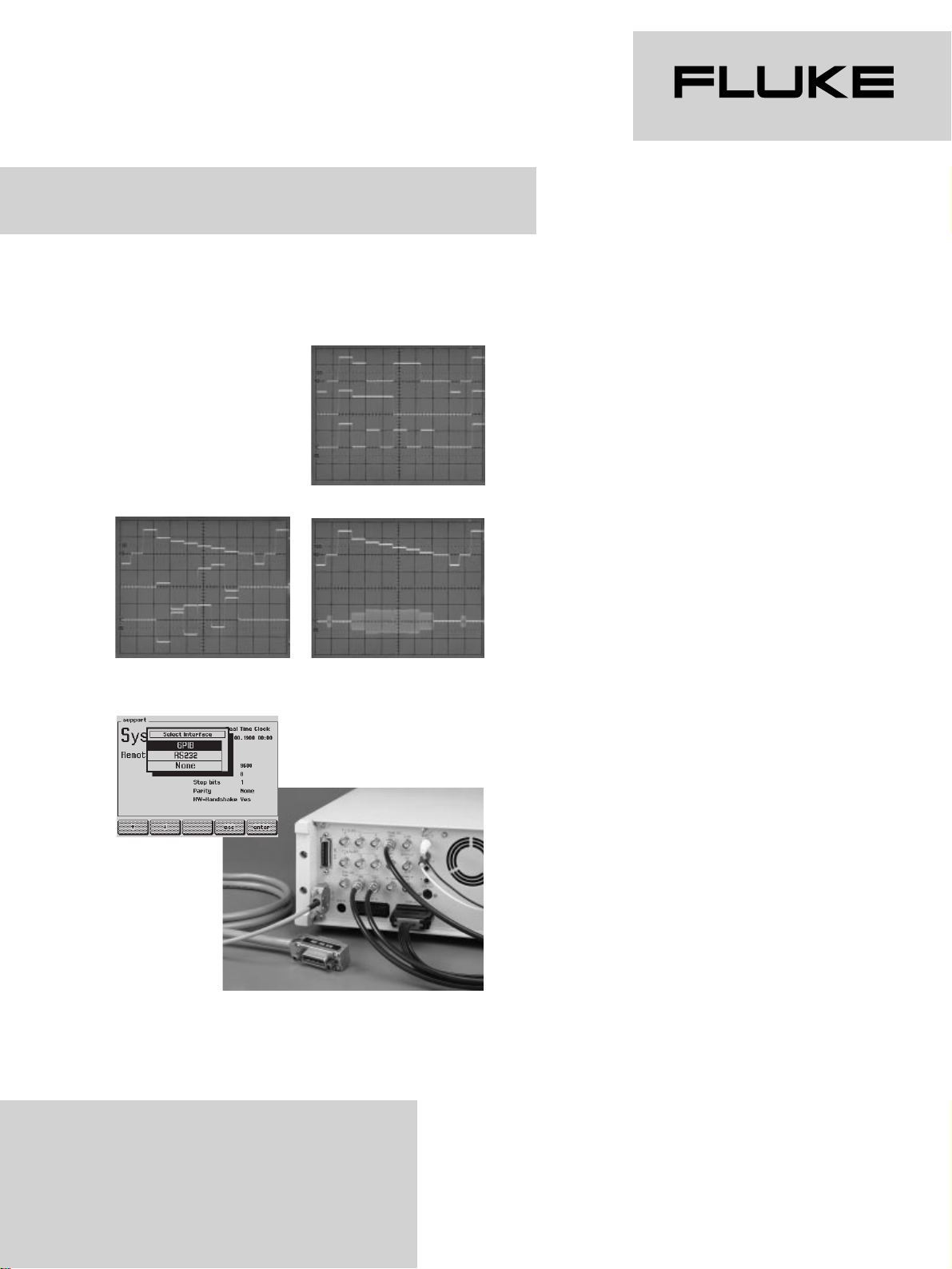
Multiple outputs
For some measurements, a composite video
signal is not enough. So, the Fluke 54000
Series’ RGB, YC and YCrCb option gives you
additional separate output signals for red,
green and blue (RGB), luminance (Y),
chrominance (C) and component outputs Cr
and Cb. The RGB and YC signals are available
at separated connectors and on the EURO AV
(SCART) connector. The RGB signal is ideal to
control devices such as components or
subassemblies directly at color decoded level.
You can even include synchronization signals
in the individual RGB signals. You’ll need the
YC output signals – which are also provided
via a special connector and cable – for testing
the S-VHS/Hi-8 input of video recorders.
These VCRs eliminate cross-color effects by
separately processing the Y and C signals,
which gives better color reproduction. The
component outputs Cr and Cb (also known as
R-Y and B-Y) are phase related to U and V
(U = 0.49 x Cb, V = 0.88 x Cr). These
component signals are used in the professional
video area and in applications where color
conversions or pattern processing are tested.
Fully programmable
You can include the Fluke 54000 Series
generators in an automated test environment
with the interface option. Offering a combined
IEEE-488 and RS-232 interface, this option
makes the instrument fully programmable from
a remote location. The IEEE-488 interface
often forms the basis of fully automated test
environments, while the RS-232 serial
interface is mostly used to control the
instrument economically from a PC in a stand
alone application. All the instrument’s
standard, function and mode settings can be
changed or retrieved via the IEEE-488 or
RS-232 interface.
RGB signals
YC signals
Fully programmable via IEE E-484 and RS-232
YCrCb signals
Interface options
•
RGB, YC (S-VHS/Hi-8), YCrCb output signals available
•
Fully programmable via combined IEEE-488 and
RS-232 interface
Making the right connections
Page 11

®
RGB OUTPUTS
Voltage (Vpp in 75Ω): 700 mV
Tolerance: 5%
2% at reference temperature
Impedance: 75Ω
Polarity: Positive
Coupling: DC
Blanking level: 0V
Offset: ± 200 mV
Synchronisation: Selectable in R, G, B or off (only
for BNC outputs)
Connector: BNC rear,
EURO AV rear
YC OUTPUTS
Luminance voltage
(Vpp in 75Ω): 1V
Tolerance: 5%
2% at reference temperature
Coupling: DC
Blanking level: 0V
Offset: ± 200 mV
Chrominance level: 100%
Tolerance: 5%
2% at reference temperature
Impedance: 75Ω
Polarity: Positive
Coupling: AC
Connector: S-VHS rear,
EURO AV rear
YCrCb OUTPUTS
Voltage (Vpp in 75Ω): 700 mV
Tolerance: 5%
2% at reference temperature
Impedance: 75Ω
Polarity: Positive
Coupling: DC
Blanking level: 0V
Offset: ± 200 mV
Connector: BNC rear
Fluke Corporation
P.O. Box 9090, Everett, WA 98206
Fluke Europe B.V.
P.O. Box 1186,
5602 BD Eindhoven,
The Netherlands
For more information call:
In the U.S.A.: (800) 443-5853
or Fax: (425) 356-5116
In Europe/M-East:
+31 (0)40 2 678 200
or Fax: +31 (0)40 2 678 222
In Canada: (905) 890-7600
or Fax: (905) 890-6866
From other countries:
+1(425) 356-5500
or Fax: +1 (425) 356-5116
Web access: http://www.fluke.com
©Copyright 1998 Fluke Corporation.
All rights reserved.
Technical specifications
IEEE-488 INTERFACE
Allows selection and control of all functions
Reference: ANSI/IEEE Std. 488-1987
Compatibility: IEEE-488.2-1987
Interface functions: AH1, SH1, L4, T6, RL1, SR1, DC1
Connector: Amphenol rear (RFI/EMI shielded)
RS-232 INTERFACE
Allows selection and control of all functions
Command set As IEEE-488 interface
Baud rate: 110 to 19200
Data bits: 7, 8
Stop bits: 1, 2
Parity check: Odd, even, no
Handshake: Software, hardware
Connector: 9 pin D-type rear (male)
Page 12
®
Reading between the lines
•
Teletext (TOP, FLOF and VPT)
•
Wide Screen Signaling (WSS) bits support
•
Easy programmable Program Delivery Control (PDC)
and Video Program System (VPS) test functions
•
Closed Caption (line 21 data services) testing
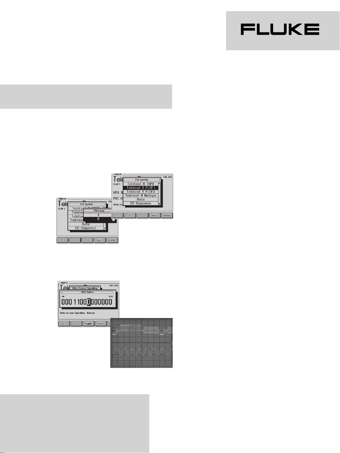
Variety of teletext modes
Wide Screen Signaling bits programming
Powerful teletext capabilities
With this data services option, you add
powerful teletext test capabilities to your Fluke
54000 Series instrument to meet the highly
specialized requirements for checking and
aligning teletext receivers and decoders. You
will have a selection of over ten teletext pages
with special contents for decoder testing at
your disposal, for use with the PAL and/or
SECAM standards. This option also supports
Wide Screen Signaling (WSS) and includes
Didon Antiope teletext signals as well as test
facilities for FLOF (Full Level One Features),
TOP (Table Of Pages) and VPT (Video
Programming by Teletext).
Wide Screen Signaling support
The need for additional signaling has
increased substantially, because of the variety
of broadcast transmissions and television set
capabilities. The Wide Screen Signaling (WSS)
bits are present in line 23 of the video signal
and contain information about the aspect ratio,
audio and data services of the transmission.
With WSS, which is included with the teletext
option, your Fluke 54000 Series generator
automatically transmits the appropriate
signaling according to the generator setting. In
manual mode, you can program the WSS bits
independently to set them to your specific
requirements.
Page 13
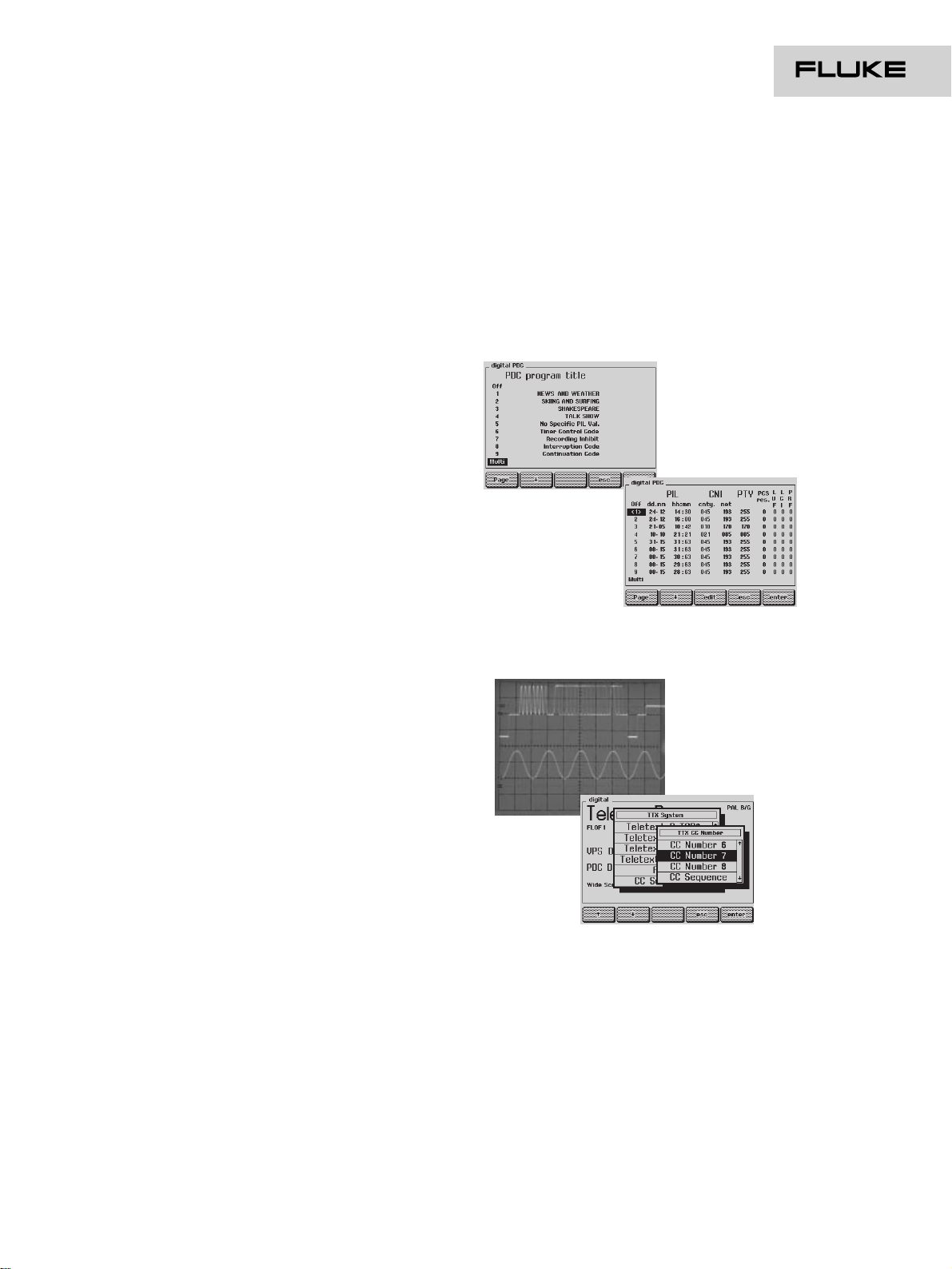
PDC programming
Selecting the
Closed Caption content
Easily programmable PDC and VPS
PDC and VPS test facilities are available
optionally with the teletext option. Both
systems use control information transmitted
with the program to start and stop recording of
that program on a VCR. For optimum flexibility,
you can use any of nine coded PDC or VPS
signals and both types of signal can even be
transmitted simultaneously. When testing PDC,
you can program PIL (date & time), CNI (country
& network), PTY, PTL and the program name.
You can even test multi labeling. In VPS mode,
you can set information on date, transmission
time, country indication, TV channel,
stereo/dual/mono sound, adult/general program
content and the program name. Special PDC
and VPS signals such as timer control code,
recording inhibit/terminate code, interruption
code and continuation code are also available.
Programming of the codes for both PDC and
VPS is simple, using the instrument's large
display and softkeys.
Versatile Closed Caption testing
Closed Caption is also known as line 21 data
services for NTSC. It is a visual representation
of the information that is simultaneously
transmitted on the audio part of a television
signal. In the USA, TV sets with screen sizes of
13" and up must have a Closed Caption
decoder. Closed Caption is not only used in
NTSC countries such as the USA, Korea and
Japan, but it can be and is used with the PAL
standard as well. The Closed Caption option on
the Fluke 54000 Series offers you both caption
and text modes in one of four operating
channels. It provides eight factory pre-coded
Closed Caption memories with a selection of
different types of information and modes, such
as roll-up, pop-on and paint-on. All line 21
decoder capabilities can easily be tested, as
memory 9 is an automatic Closed Caption
sequence of memories 1 to 8.
®
Page 14

TELETEXT DIDON ANTIOPE
(CCIR system A)
Reference: CCIR Rec. 653-1
CCIR Doc. 11/345-E
System: 625 line system
Data line: 20, 21, 333, 334
Signalling method: Binary NRZ
Clock frequency: 6.203125 MHz
Tolerance: 3 ppm for +5 to +45 °C
1 ppm at reference temperature
Aging: ≤ 2 ppm per year
Level: 7/3 of sync amplitude for '1'
Black level for '0'
Tolerance: 0 to -10% for '1'
3% of sync amplitude for '0'
TELETEXT UK (CCIR system B)
Reference: CCIR Rec. 653-1
CCIR Doc. 11/282-E
System: 625 line system
Data line: 13, 14, 20, 21, 326, 327, 333, 334 for 8
line mode
20, 21, 333, 334 for 4 line mode
Signaling method: Binary NRZ
Clock frequency: 6.9375 MHz
Tolerance: 3 ppm for +5 to +45 °C
1 ppm at reference temperature
Aging: ≤ 2 ppm per year
Level: 66% of the difference between black level
and peak white level
Black level for '0'
Tolerance: 6% for '1'
2% of sync amplitude for '0'
Technical specifications
WSS
Reference: ETSI, ETS 300 294, November 1994
PALplus system description, Revision 3.0,
January 1994
Rec. ITU-R BT.1119
System: 625 line system
Data line: 23 (field 1)
Signalling method: Bi-phase coding, NRZ-L
Clock frequency: 5 MHz
Tolerance: 3 ppm for +5 to +45 °C
1 ppm at reference temperature
Aging: ≤ 2 ppm per year
Level: 500 mV for '1' at 700 mV maximum video
level
Black level for '0'
Tolerance: 5% for '1'
3% of sync amplitude for '0'
PDC
Reference: EBU SPB 459 Revision 2
Specification of the domestic video Program
Delivery Control system
February 1992
System: TELETEXT UK (CCIR system B)
Programming: All parameters
Labeling: Single, multi
VPS
Reference: Technische Richtlinie ARD/ZDF
Nr. 8 R 2
Video Program System
EBU SPB 459 Revision 2
Specification of the domestic video Program
Delivery Control system
February 1992
System: 625 line system
Data line: 16
Signalling method: Bi-phase modulation
Clock frequency: 5.0 MHz
Tolerance: 3 ppm for +5 to +45 °C
1 ppm at reference temperature
Aging: ≤ 2 ppm per year
Level: 500 mV for '1' at 700 mV maximum video
level
Black level for '0'
Tolerance: 5% for '1'
3% of sync amplitude for '0'
Programming: All parameters
CLOSED CAPTION
Reference: FCC 47 CFR Part 15
Report No: E-7709-C
Draft EIA-608
System: 525 line system
625 line system
Data line: 21 (field 1 and field 2)
Signalling method: Binary NRZ
Clock frequency: 503.4965 kHz for 525 line system
500 kHz for 625 line system
Tolerance: 3 ppm for +5 to +45 °C
1 ppm at reference temperature
Aging: ≤ 2 ppm per year
Level: 50 IRE (50%) for '1'
0 IRE (0%) for '0'
Tolerance: 5 IRE for '1'
1 IRE for '0'
Operation mode: CC1 to CC4
T1 to T4
Fluke Corporation
P.O. Box 9090, Everett, WA 98206
Fluke Europe B.V.
P.O. Box 1186,
5602 BD Eindhoven,
The Netherlands
For more information call:
In the U.S.A.: (800) 443-5853
or Fax: (425) 356-5116
In Europe/M-East:
+31 (0)40 2 678 200
or Fax: +31 (0)40 2 678 222
In Canada: (905) 890-7600
or Fax: (905) 890-6866
From other countries:
+1(425) 356-5500
or Fax: +1 (425) 356-5116
Web access: http://www.fluke.com
©Copyright 1998 Fluke Corporation.
All rights reserved.
®
Page 15
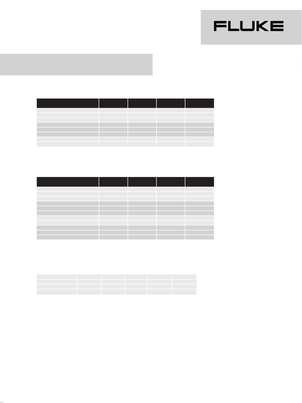
®
Example: 54100P01/021
Fluke 54100 Video Signal Generator with
PAL standard, Teletext + WSS, PDC + VPS, RGB + YC + YCrCb, IEEE + RS-232, a German language Operating
manual and an European line cord.
Option:
54091 19” rackmount
Pre-configuration models
Fluke 54100 Video Signal Generator models (option included):
54100 5410 0 54100 5 4100
M01/nnn P01/nnn N01/nnn S01/nnn
PAL standard
••
NTSC standard
••
SECAM standard
••
Teletext + WSS
•• •
PDC + VPS
•• •
Closed Caption
••
RGB + YC + YCrCb
••••
IEEE + RS-232
••••
Fluke 54200 TV Signal Generator models (option included):
54200 54200 54200 54200
M01/nnn P01/nnn N01/nnn S01/nnn
PAL standard
••
NTSC standard
••
SECAM standard
••
Teletext + WSS
•• •
PDC + VPS
•• •
Closed Caption
••
RGB + YC + YCrCb
••••
IEEE + RS-232
••••
Analog stereo
••••
NICAM stereo
•• •
BTSC stereo
••
Operating manual languages and line cords (/nnn versions):
Europa USA UK Swiss Australia
English /001 /003 /004 /005 /008
French /011 /013 - /015 German /021 - - /025 -
Page 16
®
Fluke Corporation
P.O. Box 9090, Everett, WA 98206
Fluke Europe B.V.
P.O. Box 1186,
5602 BD Eindhoven,
The Netherlands
For more information call:
In the U.S.A.: (800) 443-5853
or Fax: (425) 356-5116
In Europe/M-East:
+31 (0)40 2 678 200
or Fax: +31 (0)40 2 678 222
In Canada: (905) 890-7600
or Fax: (905) 890-6866
From other countries:
+1(425) 356-5500
or Fax: +1 (425) 356-5116
Web access: http://www.fluke.com
©Copyright 1998 Fluke Corporation.
All rights reserved.
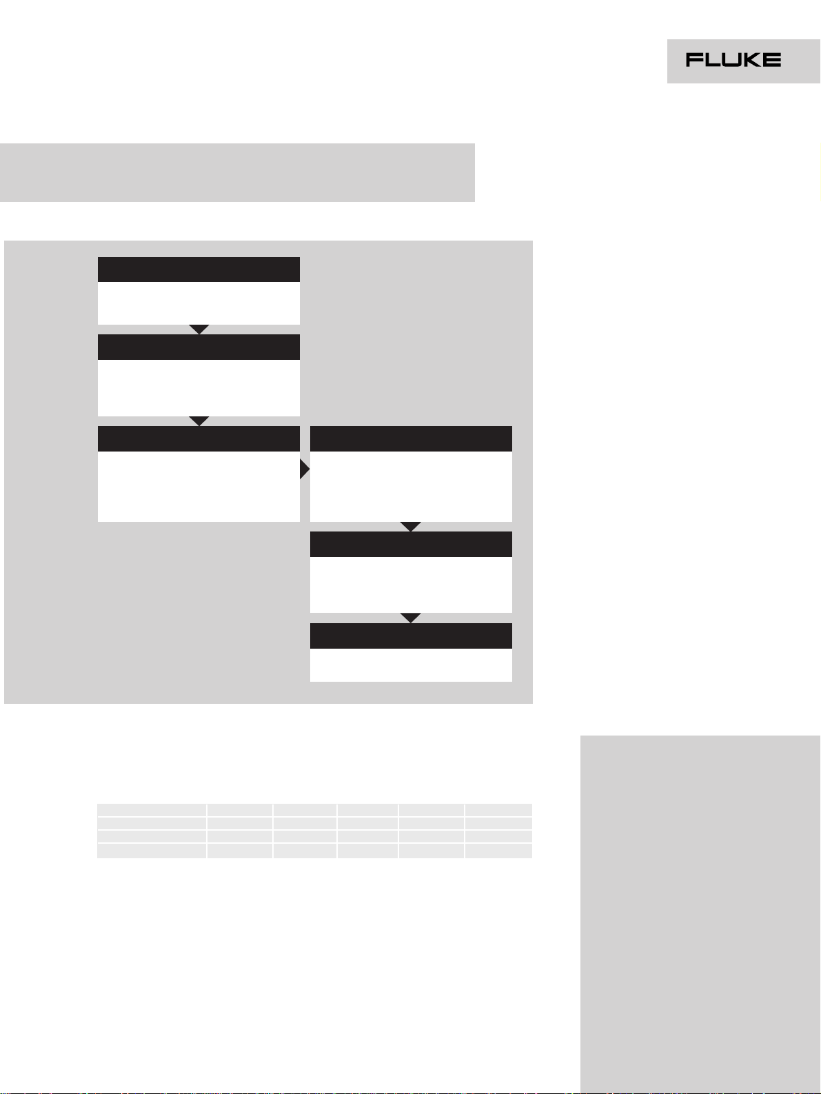
Installation accessories
❒ 54091 19” rackmount
TV System options (tick at least one)
❒ 54011 PAL standard
❒ 54012 NTSC standard
❒ 54013 SECAM standard
Basic models (tick at least one)
❒ 54100/nnn Video Signal Generator
❒ 54200/nnn TV Signal Generator
Data service options
❒ 54021 Teletext + WSS
❒ 54022 PDC + VPC (only in
combination with option 54021)
❒ 54023 Closed Caption
Interface options
❒ 54031 RGB + YC + YCrCb
❒ 54032 IEEE + RS-232 interface
Sound options (for 54200/nnn only
tick at least one)
❒ 54061 Analog stereo
❒ 54062 NICAM stereo
❒ 54063 BTSC stereo
Remark: options are also service center
retrofittable
Customer specified configurations
Example: 54100/021 + 54011 + 54021 + 54022 + 54032 + 54091
Fluke 54100 Video Signal Generator with a German language Operating
manual, an European line cord, PAL standard, Teletext + WSS, PDC +
VPC, IEEE + RS-232 and 19” rackmount.
Please contact your Fluke sales representative to optimize the
configuration to your personal requirements.
Operating manual languages and line cords (/nnn versions):
Europa USA UK Swiss Australia
English /001 /003 /004 /005 /008
French /011 /013 - /015 German /021 - - /025 -
Page 17

ENVIRONMENTAL CONDITIONS
Environment: Laboratory equipment Class 5
(MIL-T-28800D)
Warming-up time: 30 min
Recalibration interval: 12 months
Temperature: +22 to +24 °C for reference temperature
0 to +50 °C for operating
-20 to +71 °C for non-operating
Reliability: MTBF = 20,000 hours
Humidity, altitude,
vibration and shock: MIL-T-28800D (Class 5)
Safety: EN 61010-1 +/A2, Class I
IEC 1010-1 +A1 +A2, Class I
CAN/CSA-C22.2 No 1010.1, Class I
EMC: EN 55011, Group 1, Class B
VDE 0875, Part 11, Group 1, Class B
CISPR 11, Group 1, Class B
FCC Part 15J, Class A
POWER REQUIREMENTS
Line voltage operating: 90 to 264V
Line frequency: 47.5 to 63 Hz
Power consumption: 60W
DIMENSIONS and WEIGHT
Width: 323 mm (12.72 in)
Height: 147 mm (5.79 in)
132.5 mm (5.22 in) without feet (≈3HE)
Depth: 417 mm (16.42 in)
Weight: Net 9.8 kg (21.6 lb)
Shipping 11.4 kg (25.1 lb)
Values stated without tolerances are typical values
General Specifications
Fluke Corporation
PO Box 9090, Everett, WA 98206
Fluke Europe B.V.
PO Box 1186, 5602 BD Eindhoven,
The Netherlands
For more information call:
In the U.S.A.: (800) 443-5853 or
Fax: (206) 356-5116
In Europe/M-East: +(3140) 2 678
200 or Fax: +(3140) 2 678 222
In Canada: (905) 890-7600 or
Fax: (905) 890-6866
From other countries: +1(206)
356-5500 or Fax: +1(206) 3565116
Web access: http://www.fluke.com
©Copyright 1996 Fluke Corporation.
All rights reserved. Printed in the Netherlands 11/96.
Date subject to alteration without notice.
XXXXXXXX Rev xxxxx
®
 Loading...