

Page 1

Clamp Meter
Service Information
WWarning
Do not service the Meter unless you are qualifi ed to do so. The service
information provided in this document is for the use of qual ified personnel
only.
To avoid electrical shock or personal injury: Al w ays remove the test leads
and input signals from the Meter bef ore openi ng t he case.
Use caution when working with vol t ages above 60V dc or 30V ac.
WWarning
To avoid false readings, which could l ead t o possi ble electric shock or
personal injury, replace the battery as soon as the bat tery indicator appears.
Y Caution
The Meter is protected throughout by double insulati on or rei nf orced
insulation. When servicing the Meter, use only specified replacement parts.
®
30
This Meter contains parts that can be damaged by stat i c discharge. Follow
the standard practices for handling stati c sensitive devices.
Introduction
This document covers the following topics relating to the calibration of the Fluke 30 Clamp Meter,
hereafter referred to as the meter:
• Required Test Equipment
• Assembly/Reassembly
• Calibration Adjustments
• Performance Check
Service
To contact Fluke, call one of the following telephone numbers:
USA and Canada: 1-888-99-FLUKE (1-888-993-5853)
Europe: +31 402-678-200
Japan: +81-3-3434-0181
Singapore: +65Anywhere in the world: +1-425-356-5500
Or, visit Fluke's Web site at www.fluke.com.
To order replacement parts, call 1-800-526-4731.
Outside U.S.A. contact your nearest service center.
-276-6196
*
Caution
PN 929042 January 1994 Rev.1, 2/98 ©1994, 1998 Fluke Corporation. All rights reserved. Printed in U.S.A. 1
Page 2
30
Clamp Meter
Required Equipment
Table 1 lists the equipment required to perform the calibration procedure.
Table 1. Calibration Equipment
Instrument Type Recommended Model
AC Calibrator Fluke 5700A
Transconductance Amplifier Fluke 5220A
Digital Multimeter Fluke 77
Lab Supply (0-10V)
Resistor (MF, 30.1 ohms, 1%) Fluke PN 296665
Resistor (MF, 27.4 ohms, 1%) Fluke PN 296368
50 Turn Current Coil 5500A coil
Preparing for Calibration
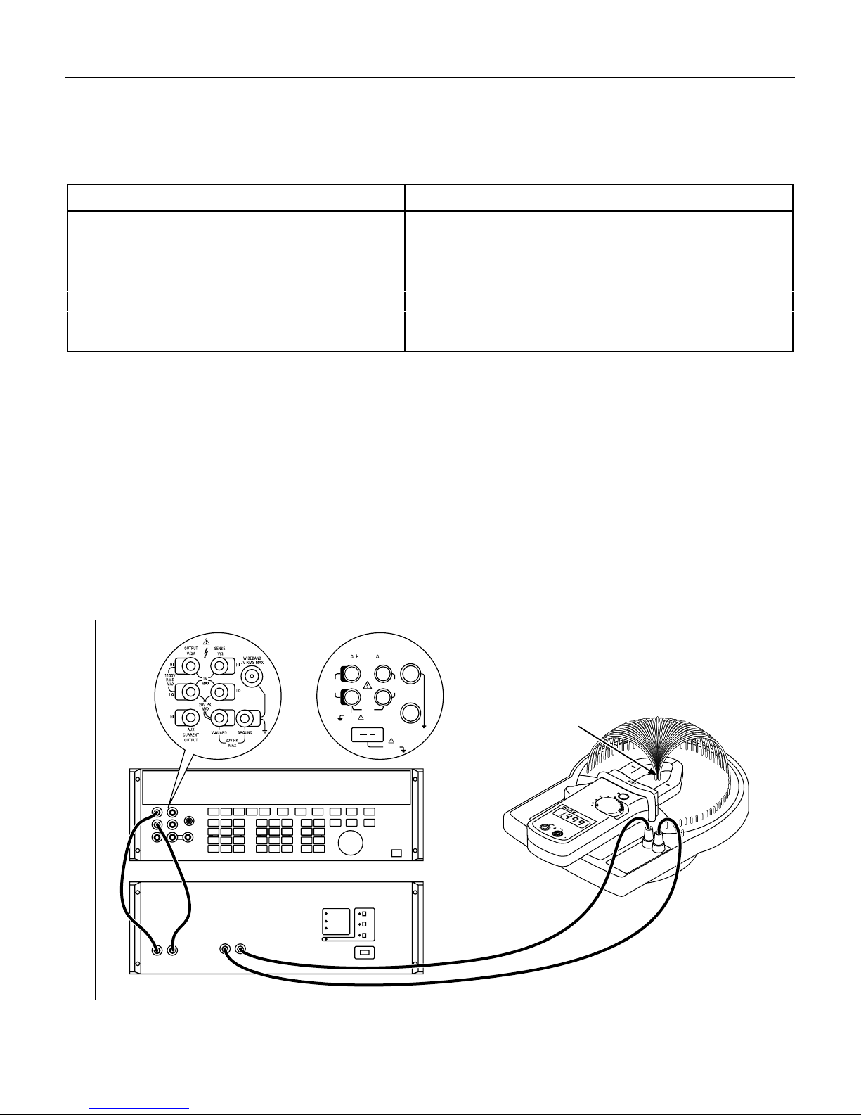
1. Configure the test equipment as shown in Figure 1.
2. Disassemble the meter by removing the four screws on the case back.
3. Remove the battery cover and front panel.
4. Turn on the meter and use a DMM to verify that the battery level is between 7 and 9 volts. If the battery
does not meet this criteria, replace the battery before proceeding with the calibration procedure.
Note
The test equipment should be allowed to warmup and stabilize for at least 30 minutes before
starting the calibration checks.
5700A/5720A 5500A
HI
LO
1V PK
MAX
A, -SENSE,
AUX V
20V PK
SCOPE
200V PK
MAX
20V
RMS
MAX
TRIG
OUT
5500A Coil
Conductor
MAX
HOLD
400A
H
200A
200
200V
600V
OFF
COM
600V
V
Calibrator
5220A
NORMAL AUX
V, ,
RTD
1000V
RMS
MAX
20V PK
MAX
TC
2
Figure 1. Calibration Equipment Configuration
rq2f.eps
Page 3

Calibration Adjustments
Complete the following procedure to calibrate the meter. Refer to Figure 2 for the adjustment locations.
AC Voltage Calibration
1. Set the meter to the 200V AC range. Connect the calibrator to the input of the meter, and program the
calibrator to 100V AC at 60 Hz. Adjust VR3 to indicate “100.0” on the display.
2. Set the calibrator to 0V and set the meter to the 600V AC range. Set the calibrator to 600V AC at
60 Hz, and verify that the display reading is within the tolerance specified in Table 2.
AC Current Calibration
1. Set the calibrator to 3.8 amps at 60 Hz.
2. Set the meter to the 200A AC range. Clamp the meter around the 5500A coil as shown in Figure 1.
Center the jaws on the coil using the indicator marks on the jaws of the meter and adjust VR2 to
indicate “191.0” on the display (adjusting to 191.0 amps ensures that the clamp meets accuracy
specifications where response roll-off occurs).
3. Set the meter to the 400A AC range and set the calibrator to 7A AC at 50 Hz. Verify that the display
reading is within the tolerance specified in Table 2. If the value is out of tolerance, balance the
calibration between the 200A and 400A ranges so that both ranges fall within the tolerance specified in
Table 2.
Calibration Adjustments
Ohms Calibration
The ohms ranges are not adjustable.
Continuity Beeper Calibration
Connect a 30.1e resistor across the meter’s input terminals, and turn VR4 slowly until the beeper sounds.
VR3
VR1
VR4
VR2
VR2
VR3
VR4
VR1
Low Battery Indication Cali brat i on
1. Disconnect the battery from the meter, and connect the lab supply to the battery terminals. Set the
power supply to 6.7V, and turn on the meter. Slowly adjust VR1 until the low battery indicator
appears.
Figure 2. Calibration Adjustment Locations
rq3f.eps
3
Page 4
30
Clamp Meter
2. Set the power supply to 7.0V, and verify that the low battery indicator goes off.
Reassembly
1. Press and release the hold switch (so the switch is down), and fit the button over the switch housing.
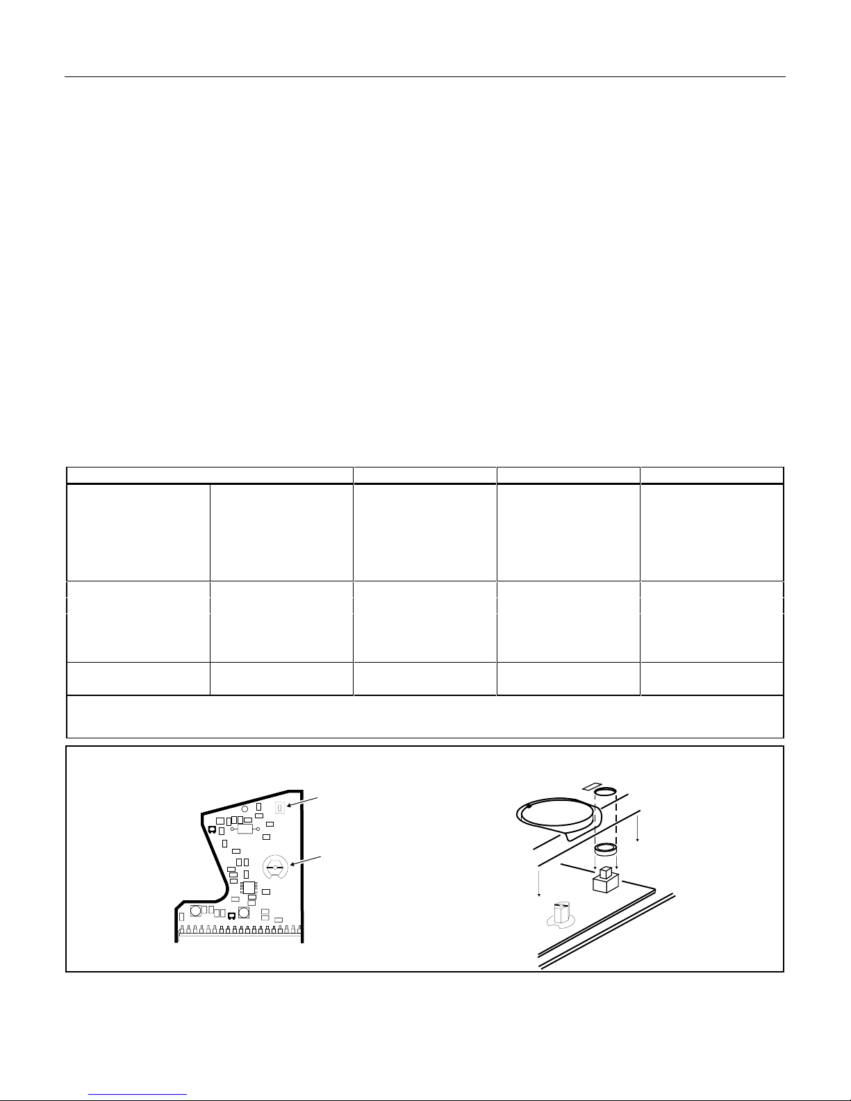
2. Set the mark on the function switch axis to the 200V AC position (horizontal position), see Figure 4.
3. Set the rotary switch on the front panel to the 200V position.
4. Reinstall the front panel, making sure the wires surrounding the PCB are not caught between the front
and back case halves.
5. Reinstall all but the battery cover screw (three screws) on the case back.
6. Reinstall the battery and battery cover. Then secure with the battery cover screw.
Performance Check
To perform a performance check on the meter, set up the test equipment as shown in Figure 1. Referring to
Table 2, set the 5700A calibrator controls as shown, and verify that the meter readings fall between the high
and low limits for each range.
Table 2. Performance Test Measurement Points
5700 Settings Range Low Limit High Limit
Current AC Freq. Hz
20A 60 200A 18.8A 21.2A
190A 60 200A 187.3A 192.7A
40A 60 400A 36A 44A
350A 50 400A 342A 358A
400A 60 400A 388A 412A
Volts AC Freq. Hz
20V 60 200V 19.5 20.5
190V 60 200V 187.4V 192.6V
60V 60 600V 56V 64
600V 60 600V 590V 610V
Resistance Ω
190Ω NA Ohms 186.9Ω 193.1Ω
To verify the continuity beeper, connect a 27.4Ω resistor (PN 296368) across the input terminals and verify the beeper
sounds.
VR2
VR2
VR2
VR3
VR3
VR3
4
HOLD SWITCH
FUNCTION SWITCH
Figure 4. Rotary Switch Position
200V
HOLD
H
rq4f.eps
 Loading...