

Page 1

®
291, 292, 294
100 MS/s Arbitrary Waveform Generators
Getting Started Manual
PN 2423319
March 2006
© 2006 Fluke Corporation, All rights reserved. Printed in the UK
All product names are trademarks of their respective companies.
Page 2

LIMITED WARRANTY AND LIMITATION OF LIABILITY
Each Fluke product is warranted to be free from defects in material and workmanship under normal use and service. The warranty period is one year and begins
on the date of shipment. Parts, product repairs, and services are warranted for 90 days. This warranty extends only to the original buyer or end-user customer of
a Fluke authorized reseller, and does not apply to fuses, disposable batteries, or to any product which, in Fluke's opinion, has been misused, altered, neglected,
contaminated, or damaged by accident or abnormal conditions of operation or handling. Fluke warrants that software will operate substantially in accordance
with its functional specifications for 90 days and that it has been properly recorded on non-defective media. Fluke does not warrant that software will be error free
or operate without interruption.
Fluke authorized resellers shall extend this warranty on new and unused products to end-user customers only but have no authority to extend a greater or different warranty on behalf of Fluke. Warranty support is available only if product is purchased through a Fluke authorized sales outlet or Buyer has paid the applicable international price. Fluke reserves the right to invoice Buyer for importation costs of repair/replacement parts when product purchased in one country is submitted for repair in another country.
Fluke's warranty obligation is limited, at Fluke's option, to refund of the purchase price, free of charge repair, or replacement of a defective product which is
returned to a Fluke authorized service center within the warranty period.
To obtain warranty service, contact your nearest Fluke authorized service center to obtain return authorization information, then send the product to that service
center, with a description of the difficulty, postage and insurance prepaid (FOB Destination). Fluke assumes no risk for damage in transit. Following warranty
repair, the product will be returned to Buyer, transportation prepaid (FOB Destination). If Fluke determines that failure was caused by neglect, misuse, contamination, alteration, accident, or abnormal condition of operation or handling, including overvoltage failures caused by use outside the product’s specified rating, or
normal wear and tear of mechanical components, Fluke will provide an estimate of repair costs and obtain authorization before commencing the work. Following
repair, the product will be returned to the Buyer transportation prepaid and the Buyer will be billed for the repair and return transportation charges (FOB Shipping
Point).
THIS WARRANTY IS BUYER'S SOLE AND EXCLUSIVE REMEDY AND IS IN LIEU OF ALL OTHER WARRANTIES, EXPRESS OR IMPLIED, INCLUDING
BUT NOT LIMITED TO ANY IMPLIED WARRANTY OF MERCHANTABILITY OR FITNESS FOR A PARTICULAR PURPOSE. FLUKE SHALL NOT BE LIABLE
FOR ANY SPECIAL, INDIRECT, INCIDENTAL, OR CONSEQUENTIAL DAMAGES OR LOSSES, INCLUDING LOSS OF DATA, ARISING FROM ANY CAUSE
OR THEORY.
Since some countries or states do not allow limitation of the term of an implied warranty, or exclusion or limitation of incidental or consequential damages, the
limitations and exclusions of this warranty may not apply to every buyer. If any provision of this Warranty is held invalid or unenforceable by a court or other
decision-maker of competent jurisdiction, such holding will not affect the validity or enforceability of any other provision.
Fluke Corporation
P.O. Box 9090,
Everett, WA 98206-9090,
U.S.A.
11/99 To register your product online, visit
Fluke Europe B.V.
P.O. Box 1186,
5602 BD Eindhoven,
The Netherlands
register.fluke.com
Page 3
Safety
This generator is a Safety Class I instrument according to IEC classification and has been designed to meet the requirements of EN61010-1:2001 (Safety Requirements for Electrical Equipment for Measurement, Control and Laboratory Use). It
is an Installation Category II instrument intended for operation from a normal single phase supply.
This instrument has been tested in accordance with EN61010-1, CSA 22.2 No. 61010-1-04 and UL 61010A-1 and has been
supplied in a safe condition. This instruction manual contains some information and warnings which have to be followed by
the user to ensure safe operation and to retain the instrument in a safe condition.
This instrument has been designed for indoor use in a Pollution Degree 2 environment in the temperature range 5 °C to
40 °C, 20 % to 80 % RH (non-condensing). It may occasionally be subjected to temperatures between + 5 °C and -10 °C
without degradation of its safety. Do not operate the instrument while condensation is present.
Use of this instrument in a manner not specified by these instructions may impair the safety protection provided. Do not operate the instrument outside its rated supply voltages or environmental range.
Warning
To avoid the possibility of electric shock:
• This instrument must be earthed.
• Any interruption of the mains earth conductor inside or outside the instrument w ill make the instrument
dangerous. Intentional interruption is prohibited. The protective action must not be negated by the use
of an extension cord without a protective conductor.
• When the instrument is connected to its supply, terminals may be live and opening the covers or removal of parts (except those to which access can be gained by hand) is likely to expose live parts.
i
Page 4
291, 292, 294
Getting Started Manual
• Disconnect the instrument from all voltage sources before opening it for any adjustment, repl acement,
maintenance or repair.
• Any adjustment, maintenance and repair of the opened instrument under voltage sh all be avoided as
far as possible and, if inevitable, shall be carried out only by a skilled person who is aware of the hazard involved.
• Make sure that only fuses with the required rated current and of the specified type are u sed for replacement. The use of makeshift fuses and the short-circuiting of fuse h olders is prohibited.
Caution
If the instrument is clearly defective, has been subject to mechanical damage, excessive moisture or
chemical corrosion the safety protection may be impaired and the apparatus should be withdrawn from use
and returned for checking and repair.
Note
This instrument uses a Lithium button cell for non-volatile memory battery back-up. Typical battery life is 5 years. In
the event of replacement becoming necessary, replace only with a cell of the correct type, a 3 V Li/Mn0
ton cell type 2032. Do not mix with solid waste stream. Do not cut open, incinerate, expose to temperatures above
60 °C or attempt to recharge. Used batteries should be disposed of by a qualified recycler or hazardous mater ials
handler. Contact your authorized Fluke Service Center for recycling information.
Caution
Do not wet the instrument when cleaning it and in particular use on ly a soft dry cloth to clean the LCD window.
20 mm but-
2
ii
Page 5
Safety
(continued)
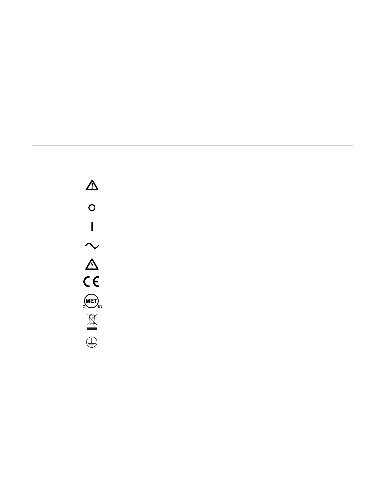
The following symbols are used on the instrument and in this manual:
Caution - refer to the accompanying documentation, incorrect operation
may damage the instrument.
Mains supply OFF.
Mains supply ON.
Alternating current.
Warning - hazardous voltages may be present.
Conforms to European Union directives:
EN61010-1-2001, EN61326
Verified by MET to be in conformance with relevant US and Canadian
Standards: CSA 22.2 No. 61010-1-04, UL 61010A-1
Do not mix with solid waste stream. Dispose using a qualified recycler or
hazardous material handler.
Protective Earth (Ground)
iii
Page 6

291, 292, 294
Getting Started Manual
ii
Page 7

EMC Compliance
These instruments meet the requirements of the EMC Directive 89/336/EEC.
Compliance was demonstrated by meeting the test limits of the following standards:
Emissions
EN61326 (1998) EMC product standard for Electrical Equipment for Measurement, Control and Laboratory Use. Test limits
used were:
a) Radiated: Class A
b) Conducted: Class B
c) Harmonics: EN61000-3-2 (2000) Class A The instruments are Class A by product category.
Immunity
EN61326 (1998) EMC product standard for Electrical Equipment for Measurement, Control and Laboratory Use. Test methods, limits and performance achieved were:
a) EN61000-4-2 (1995): Electrostatic Discharge: 4 kV air, 4 kV contact Performance A.
b) EN61000-4-3 (1997): Electromagnetic Field: 3 V/m, 80 % AM at 1 kHz Performance A.
c) EN61000-4-11 (1994): Voltage Interrupt: 1 cycle, 100 % Performance A.
d)
EN61000-4-4 (1995): Fast Transient: 1 kV peak (ac line), 0.5 kV peak
(signal lines and RS232/GPIB ports)
Performance A.
v
Page 8

291, 292, 294
Getting Started Manual
e) EN61000-4-5 (1995): Surge: 0.5 kV (line to line), 1 kV (line to ground) Performance A.
f)
EN61000-4-6 (1996): Conducted RF: 3 V, 80 % AM at 1kHz
(AC line only; signal connections <3 m not tested)
According to EN61326 the definitions of performance criteria are:
Performance criterion A: ‘Duri ng test normal performance within the specification limits.’
Performance criterion B: ‘Duri ng test, temporary degradation, or loss of function or performance which is self-recovering’.
Performance A.
Performance criterion C:
To ensure continued compliance with the EMC directive the following precautions should be observed:
a) connect the generator to other equipment using only high quality, double-screened cables.
b) after opening the case for any reason ensure that all signal and ground connections are remade cor-
rectly before replacing the cover. Always ensure all case screws are correctl y refitted and tightened.
c) In the event of part replacement becoming necessary, only use components of an identical type. Refer
to the Service Manual.
‘During test, temporary degradation, or loss of function or performance which requires operator
intervention or system reset occurs.’
Cautions
vi
Page 9

Table of Contents
Title Page
Introduction .................................................................................................................... 1
Before you Start ............................................................................................................. 1
Mains Supply Voltage................................................................................................ 1
Externally Applied Voltages....................................................................................... 2
Controls and Connections.............................................................................................. 2
Model 291 Front Panel.............................................................................................. 3
Principal Controls And Connectors............................................................................ 4
The Compact Flash Card Reader/Writer ................................................................... 11
The Liquid Crystal Display Panel............................................................................... 11
Contrast adjustment.............................................................................................. 11
Multi-Channel Instruments - Front Panel Differences................................................ 12
Using the Instrument...................................................................................................... 13
Starting up................................................................................................................. 13
Generating Sine Waves............................................................................................. 15
Generating a Swept Output....................................................................................... 18
Other Standard Waveforms....................................................................................... 19
Triggered Modes ....................................................................................................... 21
vii
Page 10

291, 292, 294
Getting Started Manual
Using the Synchronization Output............................................................................. 23
Tone Mode................................................................................................................ 24
Saving and Recalling Settings....................................................................................... 25
Using the instrument's Compact Flash Card Reader/Writer...................................... 25
Storing and Recalling Set-Ups ............................................................................. 25
Removing the Memory Card ................................................................................ 26
Arbitrary Waveforms...................................................................................................... 27
Creating a New Waveform ................................................................................... 27
Modifying a Waveform.......................................................................................... 28
Setting the Repetition Rate .................................................................................. 30
Other Functions............................................................................................................. 31
viii
Page 11

Getting Started
Introduction
This Getting Started Manual for the model 291, 292 and
294 100 MS/s Arbitrary Waveform Generators is
designed to provide an initial understanding of the way
the instruments are operated. The manual is set out in
the form of a tutorial, guiding you through a series of
basic front panel operations in order to familiarize you
with the controls and the modes of operation.
The Users Manual contains detailed specifications and
descriptions of all the functions and operations accessible
both from the front panel and by means of the remote
interfaces.
Before you Start
Mains Supply Voltage
Check that the instrument operating voltage marked on
the rear panel is correct for the local supply. If it is
necessary to change the operating voltage, follow the
procedure described in appendix A of the Users Manual.
1
Page 12
291, 292, 294
Getting Started Manual
Externally Applied Voltages
Caution
To avoid risk of damage to the instrument:
Do not apply external voltages to the
SYNC OUT or MAIN OUT sockets.
Do not apply external voltages exceeding
±10 V to the TRIG IN, MODULATION IN,
SUM IN or HOLD IN sockets.
Do not apply external voltages exceeding
+5 V or -1 V to the REF CLOCK IN/OUT or
ARB CLOCK IN/OUT rear panel sockets.
Controls and Connections
This section is designed to familiarize you with the 100
MS/s Arbitrary Waveform Generator's basic controls and
connectors. There are three versions of the instrument,
models 291, 292 and 294 being single-, 2- and 4-channel
versions respectively.
The Users Manual covers all three instruments. For this
Getting Started Manual we refer to the model 291 singlechannel instrument, except where multi-channel
operations are considered.
2
Page 13
Getting Started
Controls and Connections
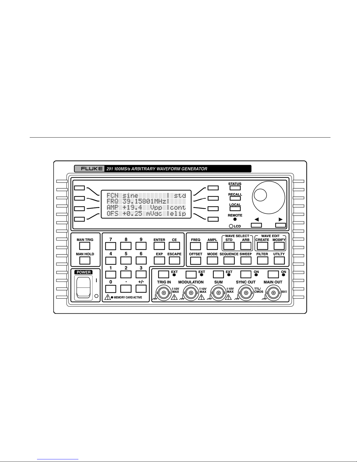
Model 291 Front Panel
shz0001f.gif
Figure 1. Single-Channel 100 MS/s Arbitrary Waveform Generator Model 291
3
Page 14
291, 292, 294
Getting Started Manual
Principal Controls And Connectors
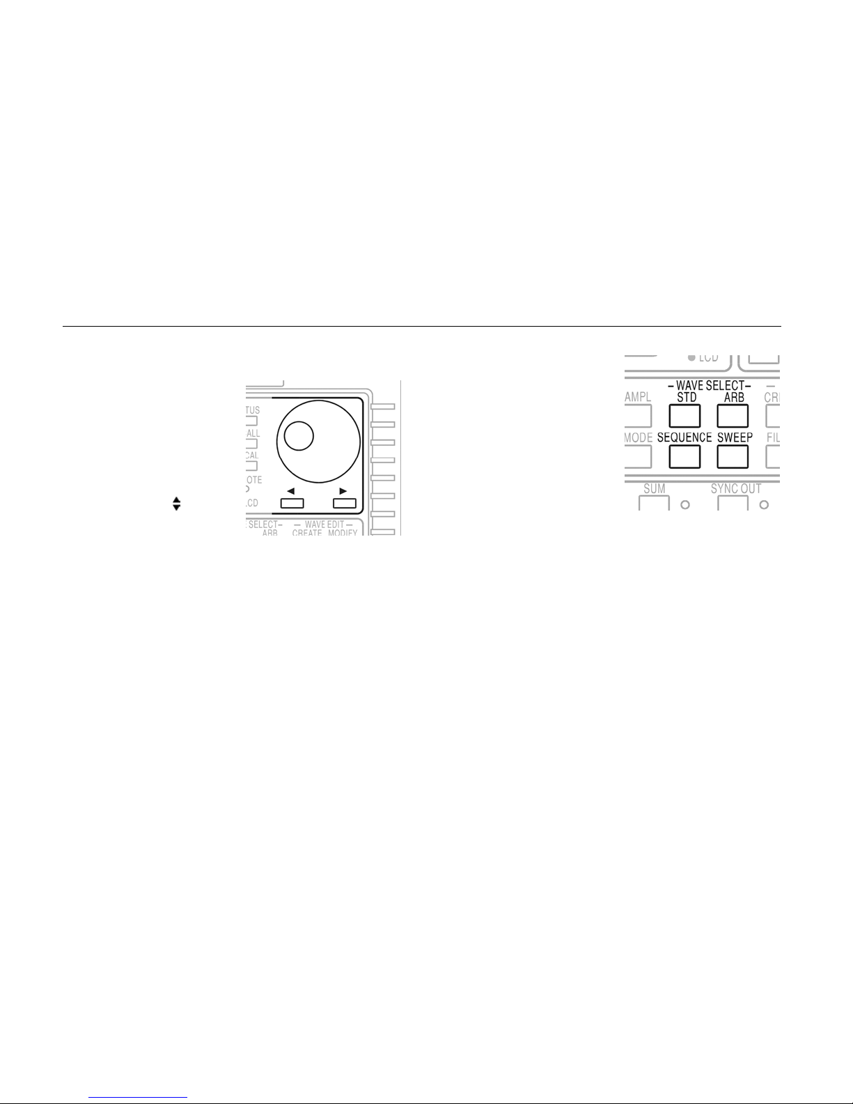
The rotary control and the
two cursor keys below it
are used to change
parameter values in the
LCD display, such as
frequency, amplitude or dc
offset.
Where the symbol
appears next to a menu
choice, the rotary control
lets you select the
appropriate item from a list.
Where a numeric parameter value is editable a flashing
cursor below one of the digits indicates the step by which
the rotary control will increment or decrement the value.
The flashing cursor can be moved left or right using the
keys below the rotary control.
shz0002f.gif
WAVE SELECT keys
The
call screens from which all
standard or already defined
arbitrary waveforms can be
selected.
Pressing the
STD key
gives the STANDARD
WAVEFORMS screen on the
LCD display, which lists the
waveforms available (sine,
square, triangle, etc.).
shz0003f.gif
Pressing the ARB key causes the LCD display to list the
arbitrary waveforms held in memory. The SEQUENCE
key is used when you want to create sequences of
arbitrary waveforms. (For information on the programming
and use of arbitrary waveforms, refer to the Users
Manual).
Pressing the
SWEEP key brings up a menu of sweep
parameters: frequency range, sweep time, direction, etc.
4
Page 15
Getting Started
Controls and Connections
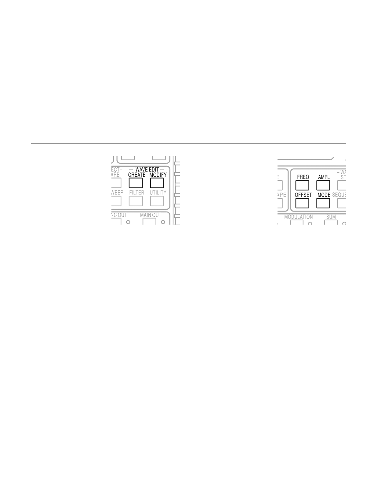
WAVE EDIT keys call
screens from which
arbitrary waveforms can be
created, modified,
combined, etc.
The CREATE and
MODIFY keys allow you to
create a new waveform or
modify an existing
waveform using the front
panel controls.
shz0004f.gif
FREQuency, AMPLitude,
OFFSET and MODE keys
display screens which
permit their respective
parameters to be edited
either from the numeric
keypad or by using the
rotary control and the
cursor keys.
shz0005f.gif
Frequency and amplitude are self-explanatory; OFFSET
refers to the instrument's ability to apply a dc offset voltage
to the waveform output, and the MODE key let s you
determine whether the output is continuous, triggered,
gated or swept and also provides for tone generation.
5
Page 16
291, 292, 294
Getting Started Manual
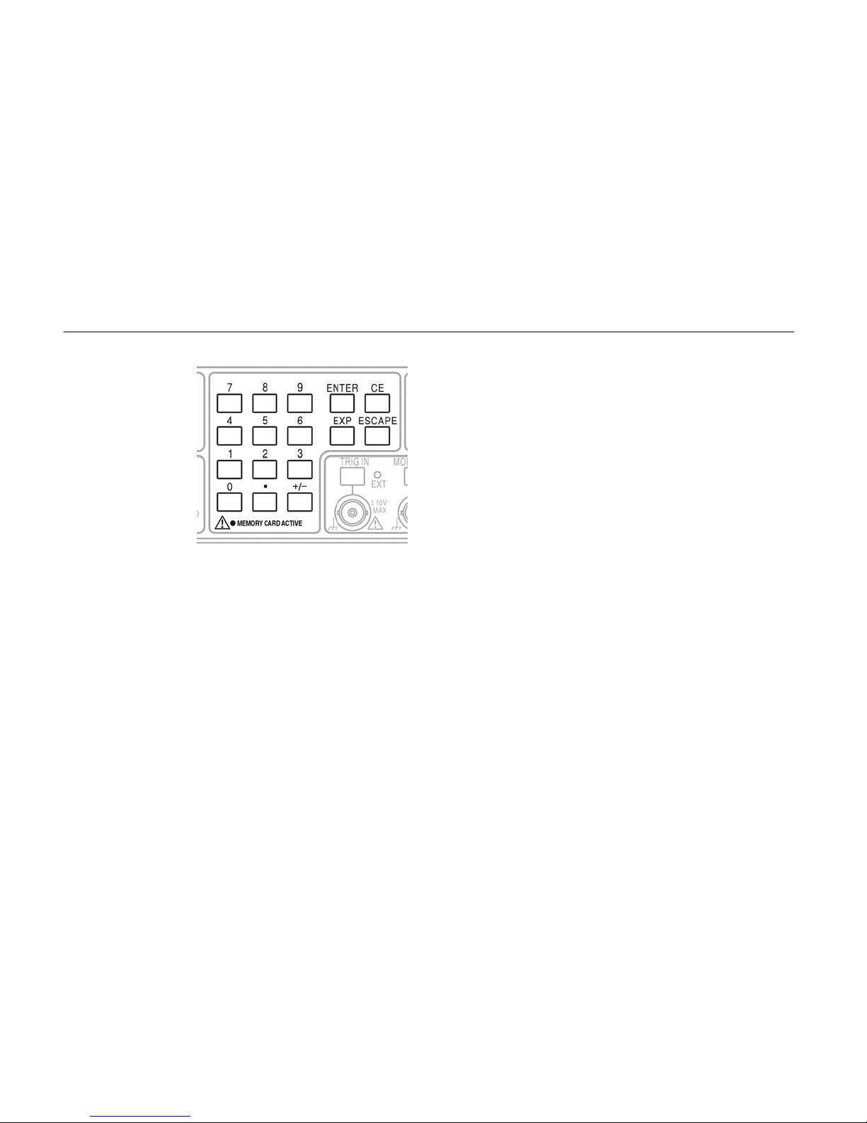
Numeric keys
permit direct entry
of a value for the
parameter currently
selected. Values
are accepted in
three formats:
integer (
20),
floating point (20·0)
and exponential
2 EXP 1).
(
shz0006f.gif
For example, to set a new frequency of 50 kHz, you can
press FREQ followed by 50000 ENTER or by
5 EXP 4 ENTER.
ENTER confirms the numeric entry and changes the
generator's setting to the new value.
CE (Clear Entry) undoes a numeric entry digit by digit.
ESCAPE returns a setting being edited to its previous
value.
The
MEMORY CARD ACTIVE lamp under the numeric
keys indicates that the Compact Flash card reader is
operating, and that the card should not be removed or its
contents may become corrupted.
On the model 291 single channel instrument the card
reader is located on the instrument's rear panel; on the
multi-channel instruments it is on the front panel.
6
Page 17
Getting Started
Controls and Connections
Each channel has a key
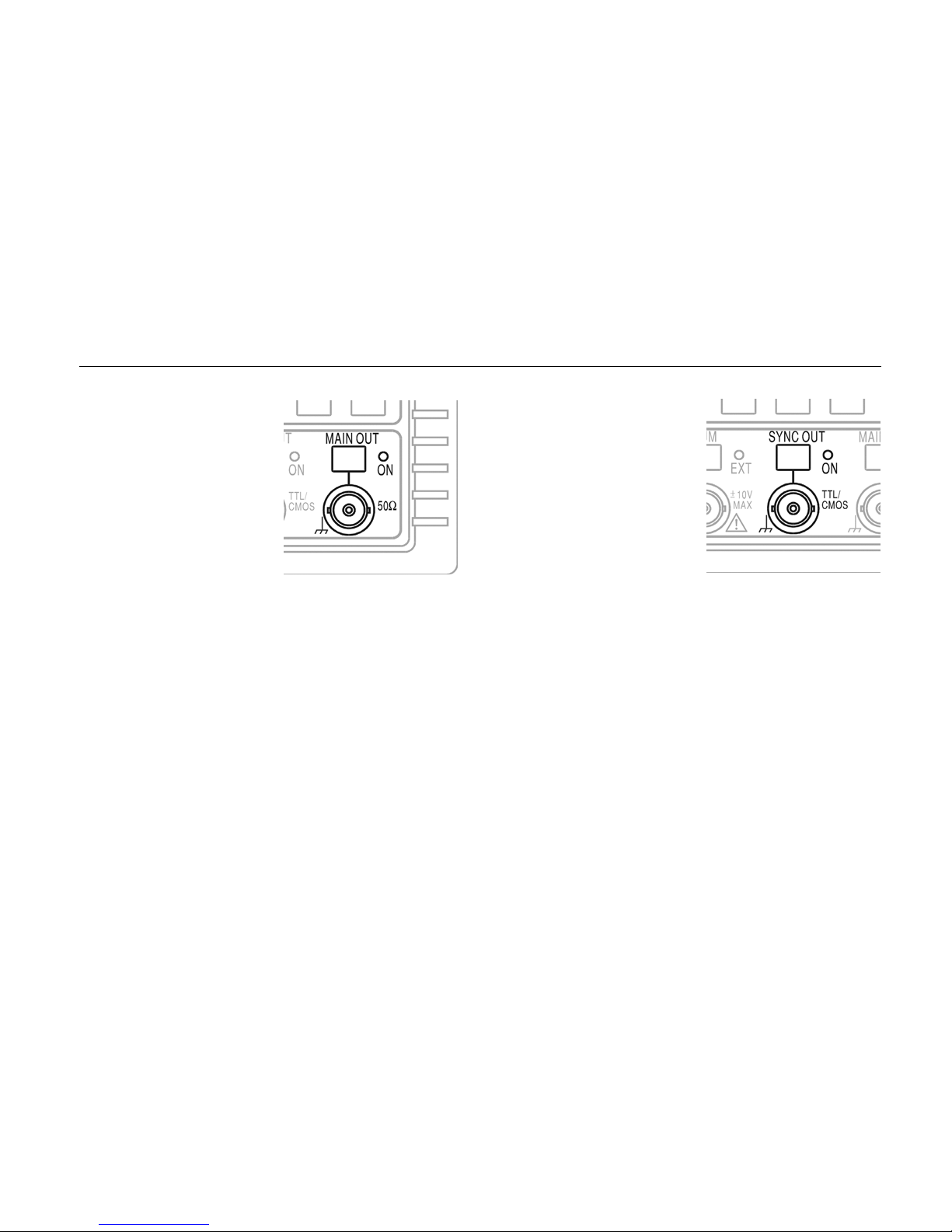
which directly switches the
MAIN OUT of that channel
on and off. The LED ON
lamp indicates when the
output is on.
shz0007f.gif
The MAIN OUT socket is the 50 Ω output from the
channel’s main generator. It provides up to 20 V p-p into
an open circuit or 10 V p-p into a matched 50 Ω load. It
can tolerate a short circuit for 60 seconds.
The
SYNC OUT key calls
an LCD display in which
you can set the parameters
of the sync output,
including whether the port
is on or off. The LED is lit
when the output is on.
shz0008f.gif
The SYNC OUT socket provides a TTL/CMOS level output
for a number of synchronization signals which you can
select using the front panel controls. It can be used to
trigger an oscilloscope or provide a Z-axis bright-up
marker, or to deliver various forms of gating and triggering
for external instruments and systems.
This drawing and the one above show the SYNC OUT and
MAIN OUT key, the LED and the socket for the singlechannel instrument. On the multi-channel versions the
MAIN OUT sockets, LEDs and keys are grouped with their
corresponding
SYNC OUT sockets, LEDs and keys.
7
Page 18
291, 292, 294
Getting Started Manual
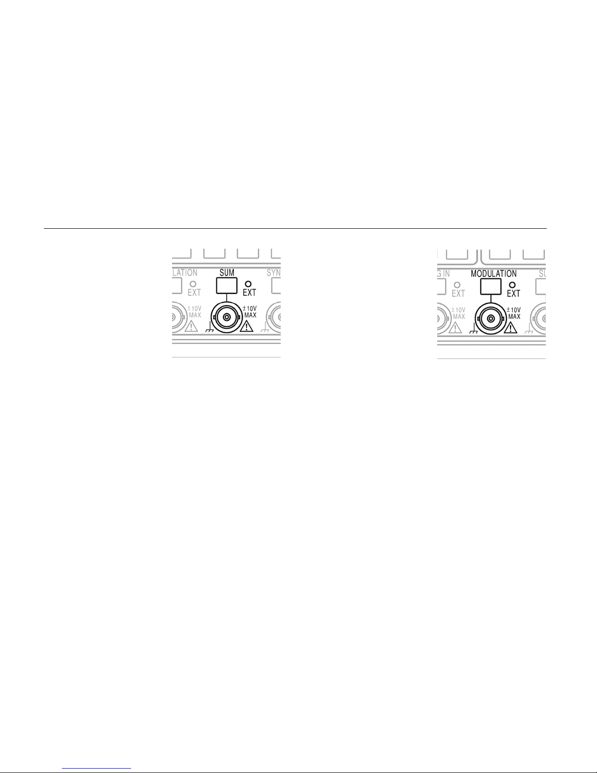
The SUM socket accepts
an external signal in the
range ±10 V which can be
added to the signal
generated internally. Multichannel instruments can
also add signals internally
from one channel to the
next.
shz0009f.gif
Pressing the SUM key brings up an LCD screen in which
you can set the source, attenuation and on/off state. The
LED indicates whether the external signal is enabled or
not.
The MODULATION socket
accepts an external signal
in the range ±10 V which
you can use to modulate
the internally-generated
signal. Multi-channel
instruments can also use
signals generated in one
channel to modulate the
next channel.
shz0010f.gif
Pressing the MODULATION key brings up an LCD screen
in which you can set the source, modulation type and
on/off state. The LED indicates whether the external
modulation signal is enabled or not.
8
Page 19
Getting Started
Controls and Connections
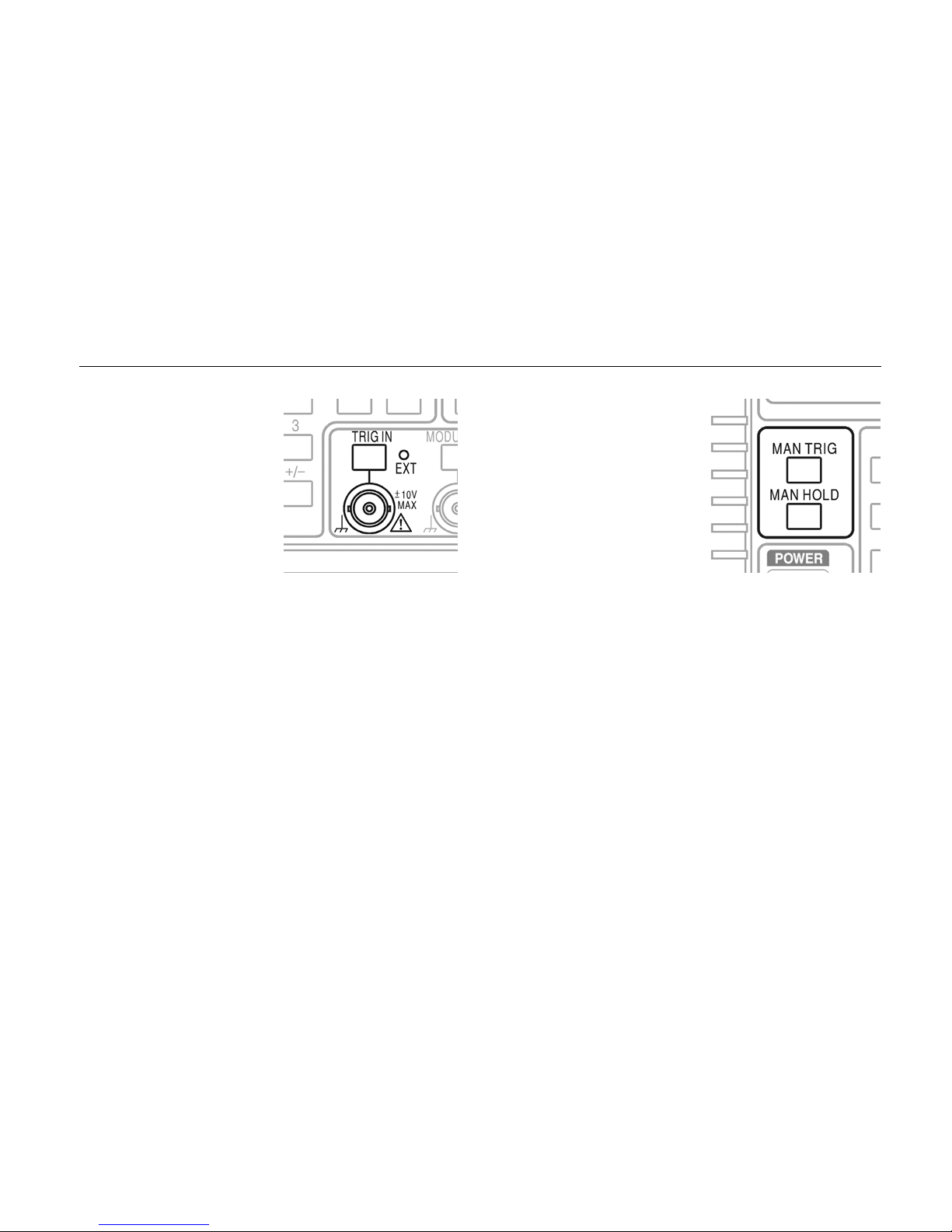
The TRIG IN socket
accepts an external trigger
signal in the range ±10 V
(with a threshold at 1.5 V)
which you can use for burst
mode or for gating.
shz0011f.gif
Pressing the TRIG IN key brings up an LCD screen in
which you can set the source and slope of the trigger
signal.
The LED indicates whether the external trigger signal is
enabled or not.
The
MAN TRIG key is used
for manual triggering (when
TRIG IN is appropriately
set) and for synchronizing
two or more linked
generators.
shz0012f.gif
The MAN HOLD key lets you manually pause arbitrary
waveform output and sweep; the output is held at the level
it was at when MAN HOLD was pressed.
9
Page 20
291, 292, 294
Getting Started Manual
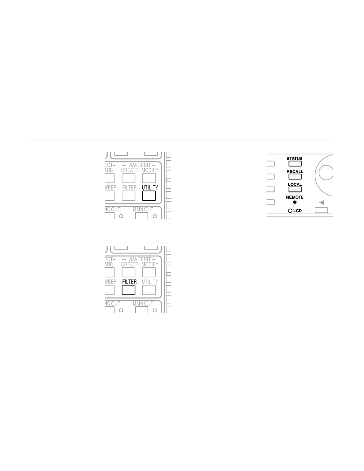
The UTILITY key gives
access to menus for a
variety of functions such as
remote control interface
set-up, power-up
parameters, error message
settings, and storing and
recalling set-ups to and
from the instrument's
memory card.
shz0013f.gif
The STATUS key always
returns the display to the
default start-up screen
(shown in figure 1 above)
which gives an overview of
the generator's status.
Pressing
STATUS again
returns the display to the
previous screen.
shz0015f.gif
The FILTER key brings up
an LCD display in which
you can override the
default output filter
settings.
10
shz0014f.gif
The RECALL key is used to recall items from the
instrument's internal non-volatile memory. Multi-channel
instruments also have a STORE key; on the singlechannel instrument this function is provided by soft keys.
LOCAL key is used to bring the instrument back to
The
local (i.e. front panel) control when it has been used in
remote mode (indicated by the
REMOTE LED).
Page 21
Getting Started
Controls and Connections
The Compact Flash Card Reader/Writer
These Arbitrary Waveform Generators use removable
Compact Flash cards to store both set-up information and
arbitrary waveforms.
On the model 291 the card reader/writer slot is on the rear
panel; on the multi-channel instruments it is on the front
panel.
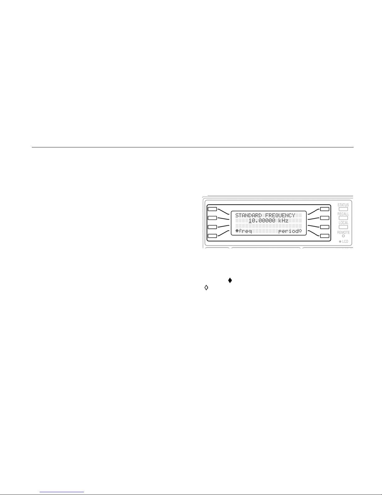
The Liquid Crystal Display Panel
The 4-line x 20-character LCD panel is used to display
and edit all the parameter values and to indicate and
change modes.
shz0016f.gif
Four soft keys at each side of the screen let you select
screen items. Selected items are indicated by a filled
diamond ( ) and unselected items by a hollow diamond
( ).
Contrast adjustment
The contrast of the LCD panel can be adjusted by means
of a rotary control behind the panel and accessed using a
small screwdriver through the hole marked LCD.
11
Page 22
291, 292, 294
Getting Started Manual
Multi-Channel Instruments - Front Panel
Differences
The Users Manual contains drawings of the model 292
and 294 front panels.
The controls of the two- and four-channel versions are the
same as those of the single channel version in all respects
except:
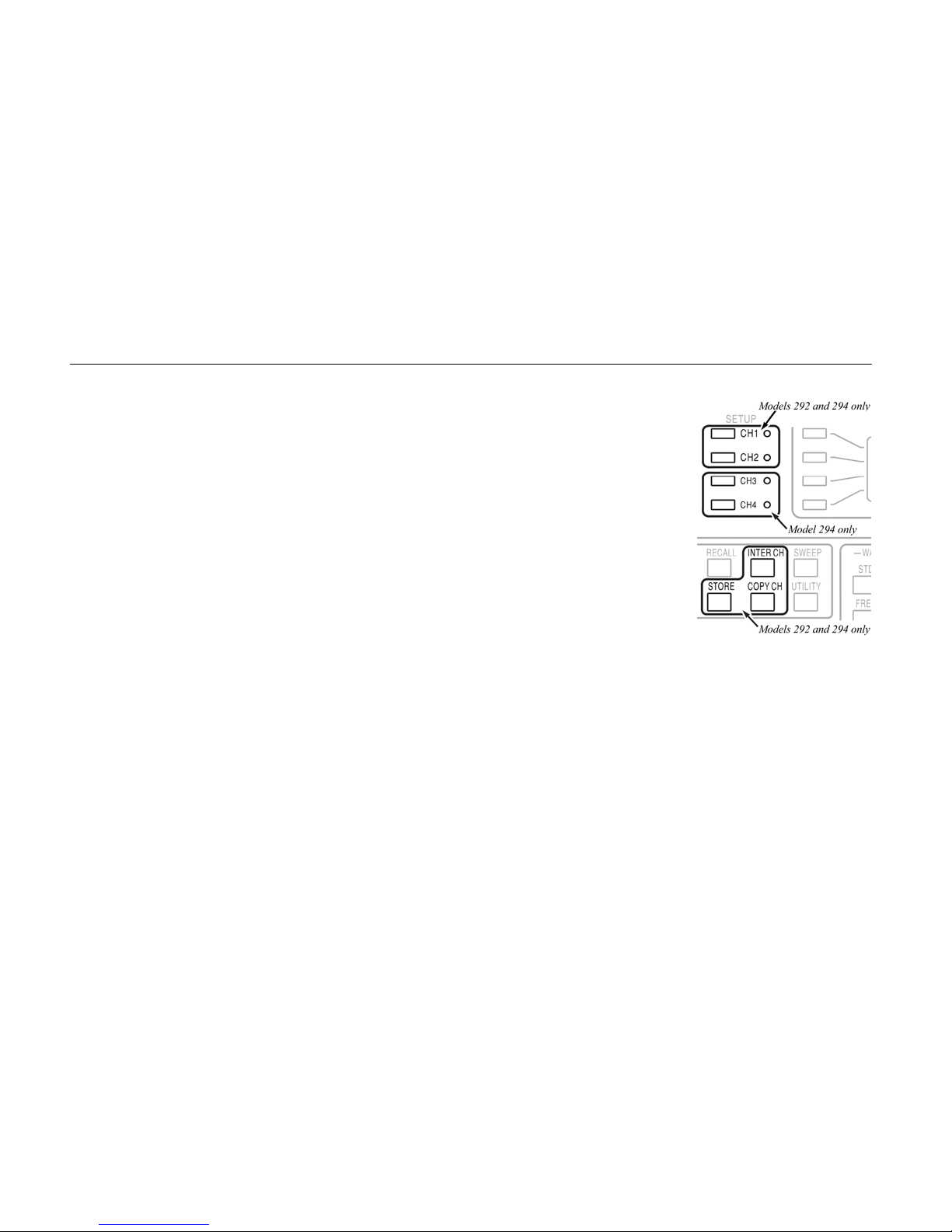
1. there are two or four pairs (respectively) of
MAIN OUT and SYNC OUT sockets, and
2. the front panel is wider to accommodate the additional
outputs, which also means that the layout of the keys
is different, and
3. the Compact Flash card reader/writer slot is on the
right side of the front panel (not the rear panel as on
the single-channel version), and
4. there are certain keys which do not exist on the
single-channel instrument, as follows:
The
STORE key: on the
single channel instrument
the store function is
accessed by means of a
soft key
The
INTER CH key: used
for phase locking between
channels
The
COPY CH key: used
for copying settings and
waveform information
between channels
shz0017f.gif
The CH1 to CH2 (2-channel) or CH4 (4-channel) SETUP
keys: used for channel selection.
When a channel select key is pressed, subsequent front
panel key presses operate on the selected channel until a
different channel select key is pressed.
LEDs adjacent to the channel select keys indicate which
channel is currently selected.
12
Page 23
Getting Started
Using the Instrument
Using the Instrument
While familiarizing yourself with the instrument you will find
it useful to observe the outputs on an oscilloscope. For
most purposes it is sufficient to connect the MAIN OUT
socket to the oscilloscope's Y input and the SYNC OUT
socket to the oscilloscope's trigger input.
If no oscilloscope is available you can still learn a great
deal about the instrument settings, since the effect of
front-panel operations is visible in the LCD display in the
form of text messages, parameter information, menus and
status information.
The following sections are written in the form of a tutorial.
Starting up
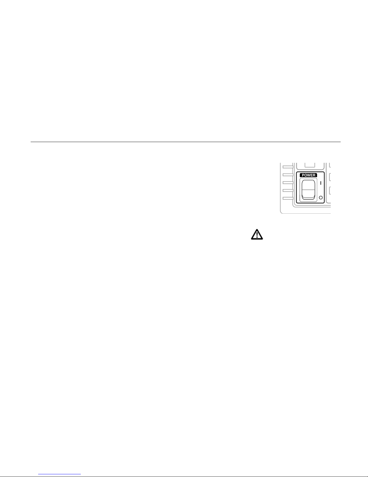
The ac POWER on/off
switch is located at the
bottom left side of the front
panel.
On multi-channel models
the switch is mounted
horizontally.
shy0015f.gif
Caution
Before connecting to the ac supply, check
that the supply voltage setting is correct for
the region. Refer to the Users Manual if the
supply voltage is different from that shown on
the rear panel.
Plug in and switch on the instrument.
At power-up the LCD panel illuminates and the instrument
performs a series of self tests. In the event that an error
message is displayed, please refer to the Users Manual.
13
Page 24

291, 292, 294
Getting Started Manual
Check the LCD display
At start-up the instrument will perform a series of internal
self tests, during which the software version number is
displayed. After a few seconds the display should be the
status screen as shown in figure 1, the Model 291 front
panel drawing above.
In the unlikely event that an internal fault is discovered
there will be a message displayed in place of the status
screen. You should refer to the Users Manual if this
happens.
Check the start-up settings
It is possible that although the status screen is displayed
correctly the settings indicated are different from those in
the front panel drawing. This happens when the
instrument has been set to resume the power-down
settings on power-up, instead of the factory defaults. To
change the power-up settings, do the following:
1. Press the
UTILITY key. This brings up a menu of
several settings and other functions.
2. Press the right cursor key sev eral times u ntil you see
power on… in the display.
4. In the next screen press the soft key to the left of
default values. The diamond will fill, indicating
that this option is now selected, so the display will
now show
default values.
5. Turn off the power, wait 10 seconds, then switch on
again.
This will ensure that the instrument is in a known state for
the purposes of this tutorial.
3. Press the soft key to the left of this menu item.
14
Page 25
Getting Started
Using the Instrument
Generating Sine Waves
Press the FREQ key. The display should look similar to
the drawing in the previous section.
With the frequency display shown you can experiment with
the rotary control and the cursor keys below it to adjust the
frequency setting. You can also experiment with entering
frequencies using the numeric keypad.
Set a frequency, for example 12.5 kHz
You can do this by either of the methods above. The
easiest is probably to key 12500 ENTER or
12.5 EXP 3 ENTER.
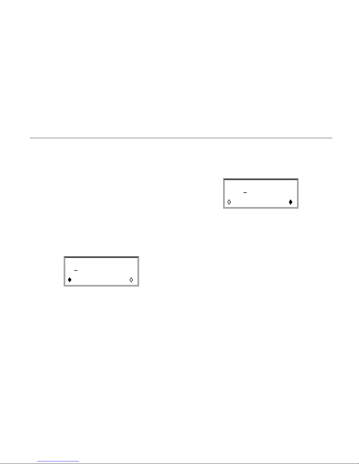
The display should look like this:
STANDARD FREQUENCY
12
.50000000 kHz
freq period
The solid diamond against the word
freq indicates that
any new keypad entry or any change made using the
rotary control will apply to the frequency.
You can also view or enter information in terms of period.
Press the soft key at the bottom right, adjacent to
the word
period.
The display should look like this:
STANDARD PERIOD
80
.000000 us
freq period
The solid diamond is now against the word period
indicating that any new keypad entry or any change made
using the rotary control will apply to the period.
The word
STANDARD in the display heading indicates
that the instrument is set up to generate one of the
standard waveforms. You can choose the waveform you
wish to generate.
15
Page 26
291, 292, 294
Getting Started Manual
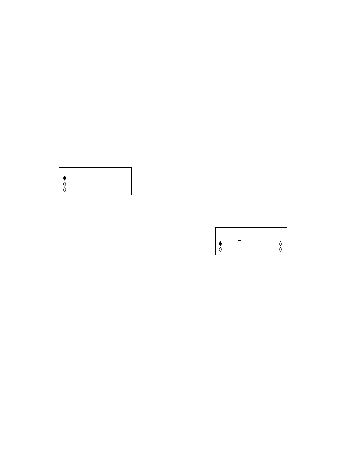
Press the
The display should look like this:
sine is the default setting. You can explore the full list of
standard waveforms using the cursor keys or the rotary
control.
The instrument can also generate arbitrary waveforms
which are specified as a series of values from -2047 to
+2047 (corresponding to a peak to peak amplitude range
of 20 V) along a timebase of up to 1,048,576 points.
These are stored on the memory card and can be created
and edited from either the front panel or on a PC using
suitable software.
Waveforms created on a PC can be written directly to the
memory card using the USB card reader/writer, or
downloaded to the instrument via the RS232, GPIB or
USB interfaces.
STD key
STANDARD WAVEFORMS
sine
square
triangle
Arbitrary waveforms are discussed later in this Getting
Started Manual.
For this part of the exercise we will concentrate on the
standard waveforms. At this point we have set up a sine
wave at 12.5 kHz.
The amplitude of the signal at the output socket is
controlled in the same manner as the frequency or period:
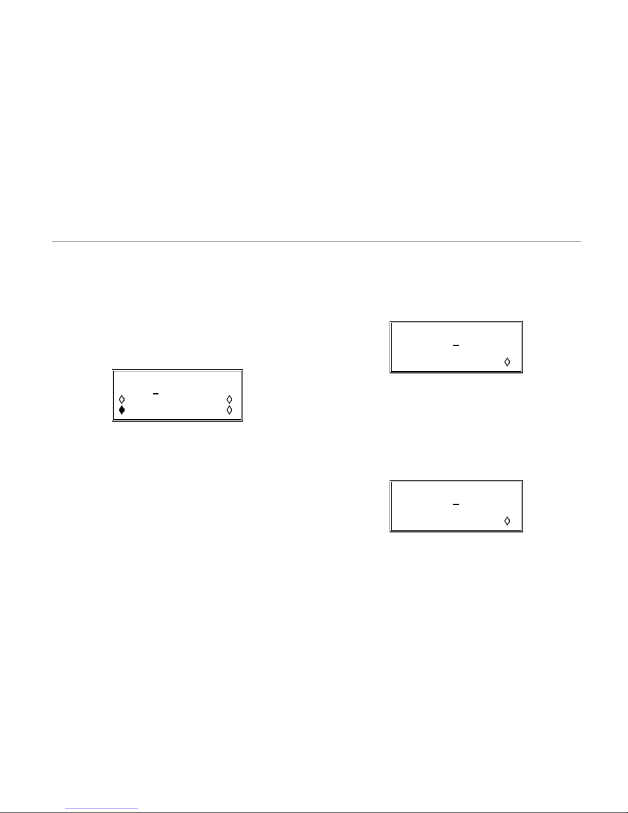
Press the AMPL key
The display should look like this:
AMPLITUDE
+2
Vpp Vrms
dBm load: hiZ
This indicates that the output amplitude is 2 V p-p into an
open circuit (
You can experiment with other settings; for example,
selecting Vrms will change the indicated value from
2.00 Vpp
The output levels above are for a high impedance load.
You can experiment to see the effect of changing the load
hiZ ).
to 707 mVrms.
.00 Vpp
16
Page 27
Getting Started
Using the Instrument
to 600Ω or 50Ω (the latter halves the output voltage
because the output impedance of the instrument is 50 Ω).
You can also display the output level in dBm (dB relative
to 1 mW in the specified load).
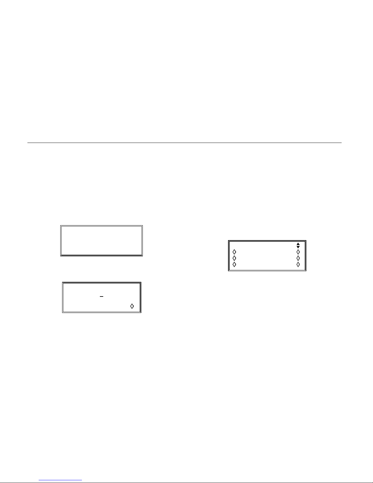
For example, if you set the load to 600
Ω and the rms
amplitude to 775 mVrms, then switch the display to dBm,
the display will show:
AMPLITUDE
+0
0.0 dBm
Vpp Vrms
dBm load:600Ω
Note that the Vrms and dBm amplitude displays are not
available for certain standard waveforms.
The following sections assume a sine wave unless
specified otherwise.
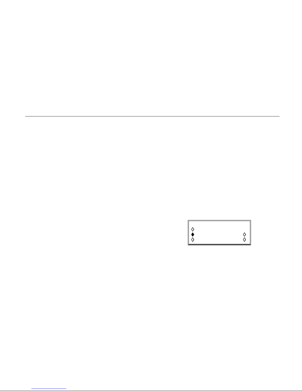
You can also apply a dc offset to the output:
Press the OFFSET key
The display will show:
DC OFFSET:
program +0
.00 mVdc
(actual +0.00 mVdc)
load:hiZ
This display assumes that the instrument has been set up
to deliver a 2 V p-p sine wave into a high impedance load.
You can change the programmed value of the dc offset.
For example, pressing
1 ENTER on the key pad changes
the display to:
DC OFFSET:
program +1
.00 Vdc
(actual +1.00 Vdc)
load:hiZ
The output stages of the instrument include a variable gain
amplifier and a 0 to 50 dB attenuator in 10 dB steps. Thus
if you subsequently reduce the amplitude such that the
17
Page 28
291, 292, 294
Getting Started Manual
stepped attenuator switches, the actual and programmed
values of the DC offset will be different. In the event you
will be warned by a text message on the display.
You can experiment, for example, by changing the
amplitude from 2 V p-p to 200 mV p-p using the key
sequence AMPL 0.2 ENTER.
The instrument will give an audible beep and the display
will show:
**** WARNING 13 ****
DC offset changed by
amplitude
If you then press OFFSET again the display will show:
DC OFFSET:
program +1
(actual +100. mVdc)
load:hiZ
This is because the amplitude change has resulted in a
change of 20 dB in the stepped attenuator, and this
change applies equally to the amplitude and the DC offset.
.00 Vdc
Note that the precise value of the actual offset also
depends upon the attenuator's stored calibration factors
and may therefore be marginally different from those
shown above.
Generating a Swept Output
You can generate swept, phase-continuous sine waves
and other waveforms.
Press the SWEEP key
The sweep set-up display is as follows:
SWEEP SETUP: off
range… type…
time… spacing…
manual… marker…
Each of the submenu items leads to a second screen in
which you can set the parameters chosen; for example the
range… soft key allows you to set the sweep range in
terms of either start and stop frequency or of center
frequency and span.
Experiment by setting up a continuous linear sweep,
taking 100 ms to go from 40 kHz to 70 kHz in the upward
direction, with a marker at the middle of the sweep
(55 kHz).
18
Page 29
Getting Started
Using the Instrument
Once all the parameters are set, you can turn the sweep
on and off using the cursor keys.
Note that the sweep marker occupies the period of one of
the steps of the sweep. The step chosen is the one with
the frequency closest to the programmed marker
frequency. If you have followed the steps above and the
sweep is turned on, you should see that the actual marker
frequency is 54.96 kHz, not 55.00 kHz.
Other Standard Waveforms
You saw earlier that the list of standard waveforms
includes sine, square, triangle, dc, negative- and positivegoing ramps, haversine, cosine, havercosine, sin(x)/x,
pulse and pulse-train waveforms. In addition, the
selections include arbitrary and sequence for simplicity of
switching between these and standard waveforms; they
do, however, have their own screens (accessed by
pressing
ARB and SEQUENCE respectively).
Most waveforms are generated by direct digital synthesis;
square waves, pulses and pulse trains, arbitrary
waveforms and sequences are generated by clock
synthesis.
There are comparative descriptions of both methods in the
Users Manual.
For the purposes of this Getting Started Manual it is not
necessary to understand the internal synthesis processes
but it is useful to know the effect on the possible frequency
resolution. For direct digital synthesis it is 10
-4
Hz
(0.1 mHz); for clock synthesis it is 10-1 Hz.
Of the standard waveforms, most are self-explanatory.
The limits of frequency and amplitude vary somewhat from
case to case and are covered in full in the specifications
section of the Users Manual. However, the pulse and
pulse-train settings are significantly different, and will be
examined next.
Select pulse on the STANDARD WAVEFORMS screen
The display will include a set-up option to the right of the
pulse selection:
STANDARD WAVEFORMS
sin(x)/x
pulse setup
pulse-train setup
The set-up selection will lead you through a series of
screens where you can define the pulse period, the pulse
width and the pulse delay.
19
Page 30
291, 292, 294
Getting Started Manual
You will find it easiest to edit these parameter values using
the rotary control.
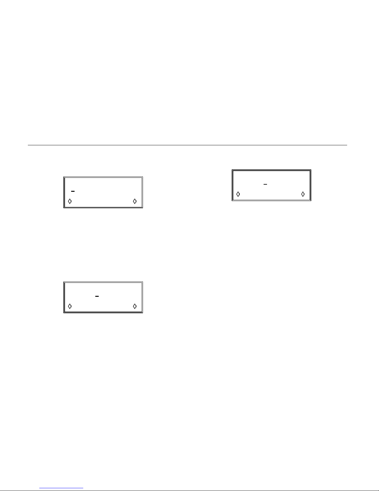
Enter pulse period
0.00000 us
15
15000pts*10.000000ns
exit next
The third line of the screen indicates the way the
waveform will be constructed (in this case, 15,000 points
clocked out at 10 ns intervals.
The actual values for the pulse width and delay may differ
slightly from the programmed values because of the way
the pulse is assembled internally. An explanation for this
is given in the Users Manual.
Enter pulse width
program+1
2.800000 us
actual +12.800000 us
exit next
After the first two screens the word next appears at the
bottom right; in the final screen it is replaced by the word
done.
Pressing the done soft key concludes the pulse set-up.
Enter pulse delay
program+2
0.000000 us
actual +20.000000 us
exit done
You can also define pulse trains of up to 10 pulses, each
of which is defined in terms of width, delay and amplitude.
They all share a common baseline voltage, which you can
set in the set-up sequence.
For a pulse train of n pulses there are 3 + 3n screens in
the set-up. The first three are used to set the number of
pulses (n), the pulse train period (i.e. the repetition period
for the entire pulse train) and the baseline voltage.
The next 3n screens set the level, width and delay for
each of the n pulses.
20
Page 31
Getting Started
Using the Instrument
Triggered Modes
So far we have considered only continuous modes of
operation. The instruments also offer gated and triggered
modes.
This section of the Getting Started Manual only covers the
burst mode of operation, which is an output of defined
length triggered by an edge at the
TRIG IN socket, a
signal taken from another channel, the internal trigger
generator or a press of the
MAN TRIG key.
The gated mode is level-sensitive; a signal at the
TRIG IN
socket or a signal from another channel determines
whether the output is on or off.
There is a detailed account of both gated and triggered
burst modes in the Users Manual.
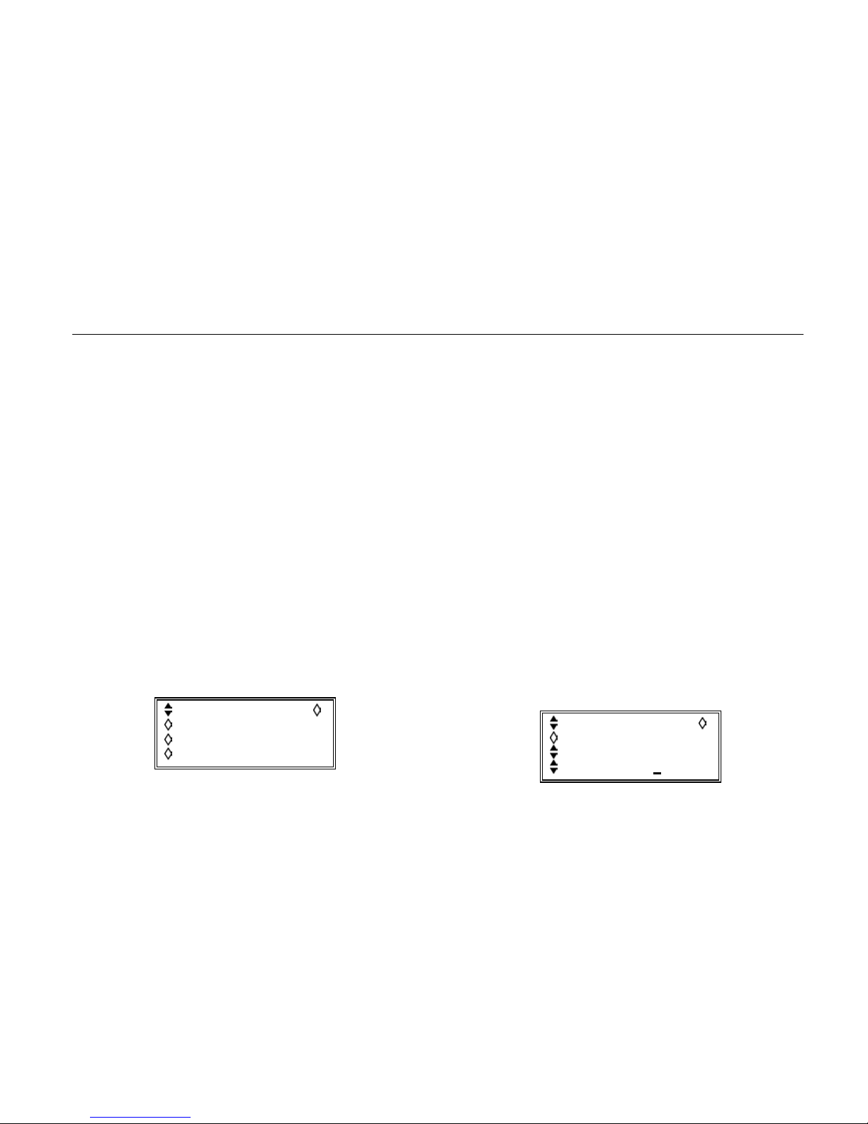
Press the TRIG IN key
You should see a display like this:
source: int force
slope: positive
level: +1.4 V
period: 1.00ms
Using the cursor key you can change the source
between the internal trigger generator, an external
input or the
MAN TRIG front-panel key. On multi-channel
instruments the source may also be another channel. For
the purposes of this exercise you should choose int as
the source.
The force soft key is used only to initiate triggering in
cases where a closed ring of generators is each waiting
for a trigger signal from its neighbor; it is in effect a manual
override trigger key for use when the source is not set to
manual.
For this exercise, we will produce a triggered burst of 3
cycles of a 12.5 kHz sine wave with a duty cycle of 1:2
(on:off). The settings for the standard wave are the same
as those discussed earlier; one cycle has a period of 80
µs. The total repetition cycle period of the trigger is 240 µs
on plus 480 µs off, total 720 µs.
Set the period to 0.72 ms (
0.00072 ENTER).
The display should now look like this:
source: man force
slope: positive
level: +1.4 V
period: 0.72ms
21
Page 32
291, 292, 294
Getting Started Manual
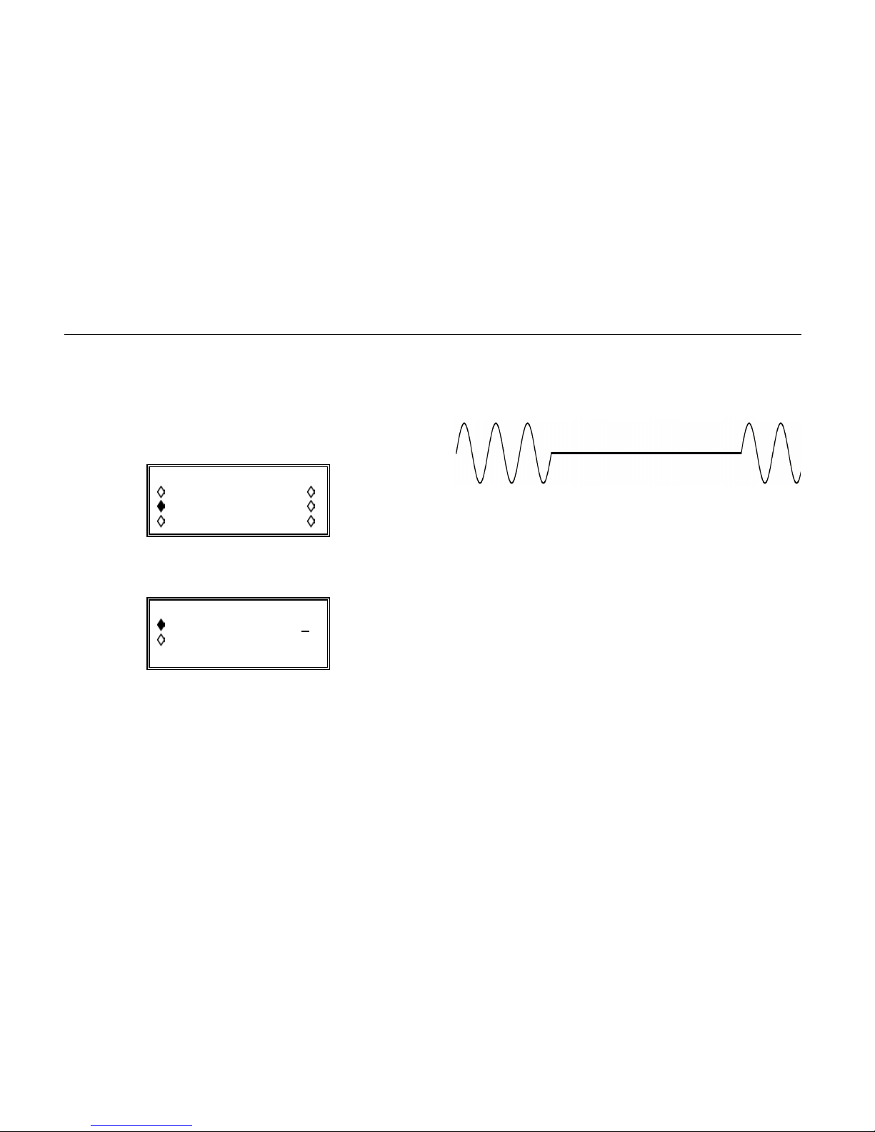
Turn on the Triggered Mode
Do this by pressing the MODE key and selecting
triggered on the screen, which should now look like
this:
MODE:
gated setup…
triggered setup…
sweep setup…
Now press the soft key for the triggered setup…
TRIGGER/GATE SETUP:
burst cnt: 0000003
phase: +000.0°
(actual: +000.0°)
You can set the number of waveform cycles to any integer
value from 1 to 1,048,575; set it to 3.
You can also control the start and stop phase of the
waveform between 0 and 359.9 degrees.
If you are observing the output on an oscilloscope
triggered from the
SYNC OUT socket, it should look
something like this:
You can observe the effect of adjusting the phase and
burst count.
22
Page 33
Getting Started
Using the Instrument
Using the Synchronization Output
The SYNC OUT socket provides various signals which
you can set up. These include the provision of a range of
trigger or bright-up marker signals for oscilloscopes, other
instruments and test devices, and signals for
synchronizing additional generators.
You should refer to the Users Manual for a full explanation
of the more complex applications of the SYNC OUT
signal; for the purposes of this Getting Started Manual we
will restrict the discussion to the generation of trigger
signals for oscilloscopes and other external devices.
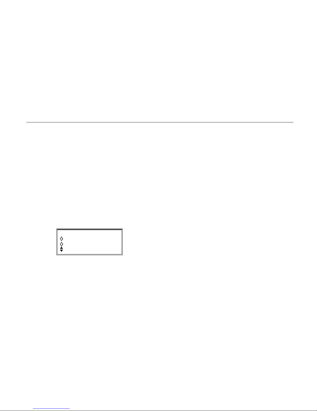
Press the SYNC key
You should see a display like this:
SYNC OUT:
output: off
mode: auto
src: waveform sync
The first soft key toggles the output between on and
off, and the second toggles the mode between auto
and manual.
The src choices are as follows:
waveform sync:
For most of the waveforms the
output is a square wave at the main
waveform frequency.
burst done:
Produces a pulse coincident with
the last cycle of the burst.
sequence sync:
Produces a pulse coincident with
the end of a waveform sequence,
(i.e. a sequence of arbitrary
waveforms). Sequence generation
is covered in full in the Users
Manual.
trigger:
Selects the current trigger signal
(internal, external, adjacent
channel or manual).
sweep sync: Outputs the sweep trigger signal.
phase lock:
Used to lock two or more
generators. Produces a positive
edge at the 0º phase point.
You can observe the effect of changing the SYNC OUT
settings on the oscilloscope' s triggering.
23
Page 34
291, 292, 294
Getting Started Manual
Tone Mode
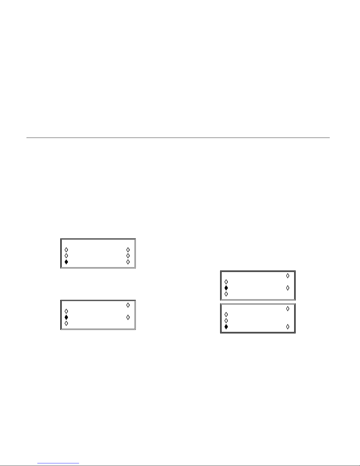
In tone mode the output is stepped through a list of up to
16 frequencies under the control of the trigger signal or
front panel MAN TRIG key.
You can control the instrument's response to the trigger
signal and the frequencies in the list from the set-up
screen.
Press the MODE key and navigate to tone
The MODE key produces a display like this (if tone is
not visible, navigate down the list using the cursor keys):
MODE:
triggered setup…
sweep setup…
tone setup…
The setup… soft key next to the tone selection leads to
the set-up screen:
TONE type: trig
2.000000 kHz #2
3.000000 kHz del
end of list #4
The trig type uses the trigger source to switch from the
current tone to the next. The other two types, gate and
fsk (frequency shift keying) are outside the scope of this
Getting Started Manual but are covered in detail in the
Users Manual.
If there are more than three tones defined in the list you
can navigate up and down using the cursor keys. You can
enter the frequency of each tone using the numeric
keypad or the rotary control, and you always have the
option to delete the currently selected tone using the del
soft key. For the unselected tones the word del is
replaced by the numeric position in the list.
As an exercise for this Getting Started Manual you could
set the frequencies of six tones to tune a guitar.
The frequencies for E, A, D, G, B, E tuning (based on
A=440 Hz) are shown in these two screens:
TONE type: trig
164.8000 Hz #1
220.0000 Hz del
293.6600 Hz #3
TONE type: trig
392.0000 Hz #4
493.8800 Hz #5
659.2600 Hz del
24
Page 35

Getting Started
Saving and Recalling Settings
You should also press the TRIG IN key and check that the
trigger source is manual.
You can now step through the six audio frequencies using
the
MAN TRIG key and listen to them on headphones
attached to the MAIN OUT socket.
One of the important uses for the tone generation
capability of a multi-channel instrument is for DTMF (dual
tone multi-frequency) testing of telephony equipment and
systems. This use is described further in the Users
Manual.
Saving and Recalling Settings
The instrument's built-in card reader/writer lets you use
Compact Flash cards to save both instrument set-ups and
arbitrary waveforms. On the single-channel instrument the
card slot is on the rear panel; on multi-channel instruments
it is on the front panel.
Using the instrument's Compact Flash Card
Reader/Writer
Place the memory card in the memory card slot, ensuring
that the pointer on the card aligns with the pointer on the
card slot. Push the card gently until it is fully engaged in
the connector. You can insert the card with the power on
or off.
When a card is inserted in a powered instrument the
message
Opening memory card
will appear on the bottom line of the screen, the
MEMORY CARD ACTIVE
lamp will light and a short beep
will sound. The card is then ready for use.
Storing and Recalling Set-Ups
Set-ups are stored on the Compact Flash card in their own
directory. You can store and recall complete set-ups using
25
Page 36
291, 292, 294
Getting Started Manual
the screens called by the STORE and RECALL keys. On
the single-channel instrument the store function is
accessed via the UTILITY menu.
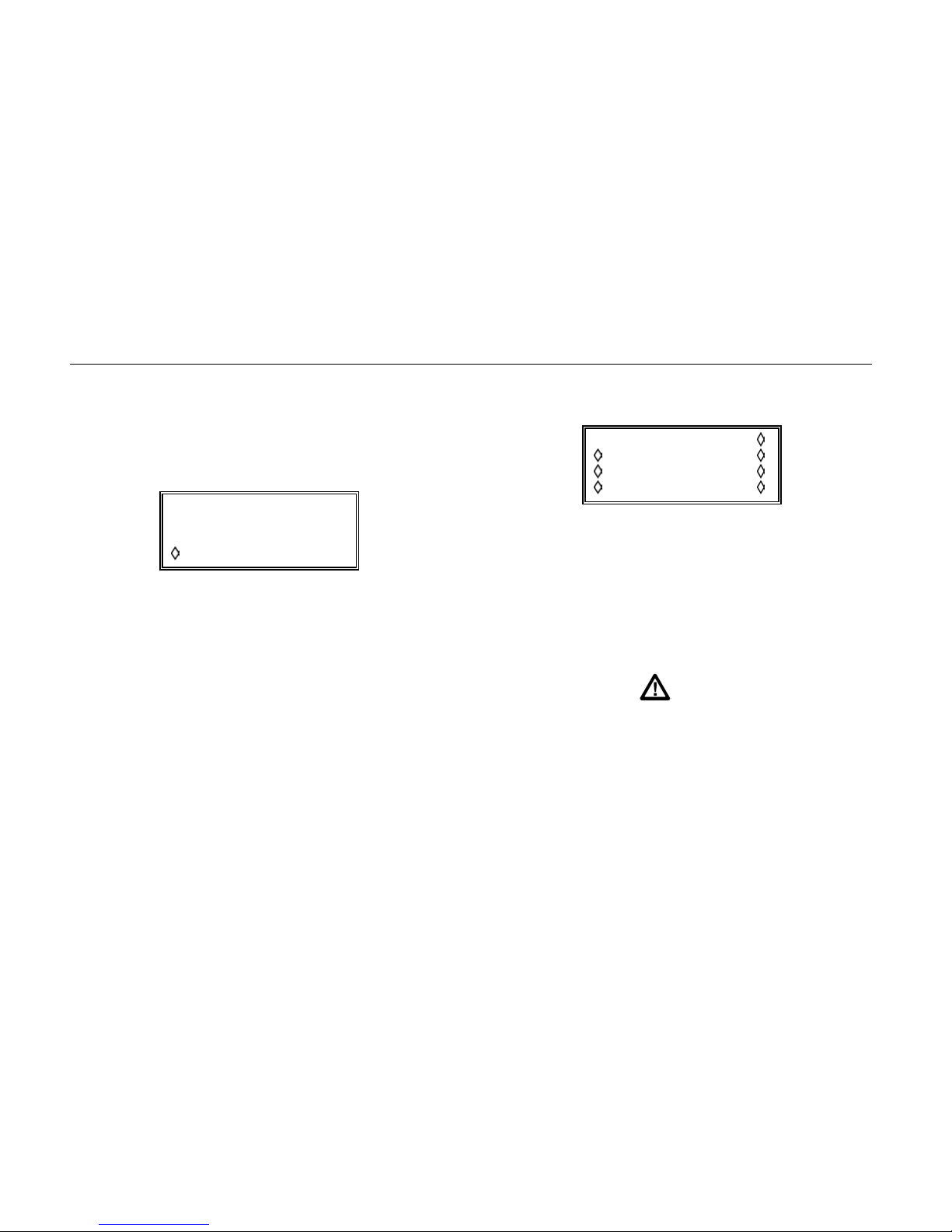
Pressing STORE or the STORE soft key calls this screen:
Save to store:
"SETUP22 "
execute
You can enter a unique name with up to eight characters
for your stored set-up using the left and right cursor keys
and the rotary control.
The left and right keys step the edit cursor through the
eight possible character positions of the name and the
rotary control is used to scroll through all valid character
choices.
Once the unique name has been entered, you can save
the current instrument set-up to that store name by
pressing the execute soft-key.
If the name already exists you will be asked whether you
want to overwrite the file.
Pressing
You can scroll through the full list of stored set-ups using
the rotary control.
RECALL calls the RECALL screen:
RECALL: execute
TESTWAVE delete
SETUP6 delete
SETUP22 default
Removing the Memory Card
To remove the memory card, first ensure that the
MEMORY CARD ACTIVE lamp is off, then pull the card
straight out of the card slot.
Caution
To avoid the risk of malfunction, card data
corruption or firmware lock-up, never remove
the memory card when the
ACTIVE
lamp is lit.
MEMORY CARD
26
Page 37
Getting Started
Arbitrary Waveforms
Arbitrary Waveforms
Arbitrary waveforms are stored on the Compact Flash card
in their own directory as <filename>.WFM, where
<filename> has up to eight characters.
Within the file and within the instrument, waveforms are
represented as a series of values from -2048 to +2047,
corresponding to the peak to peak output voltage range;
the number of points in the series can be anything from 8
to 1,048,576. The default number of points for a new
waveform is 1024.
Waveforms can be defined using many different methods,
of which the easiest is to use is a waveform synthesis
program on a PC. The CD-ROM supplied with the
instrument includes applications for this purpose.
Waveforms can be moved between the PC and the
instrument using either a remote control interface (RS232,
USB or GPIB) or the Compact Flash card.
Waveforms can also be defined, edited, copied and
pasted using the front-panel controls, provided a Compact
Flash card is present.
Creating a New Waveform
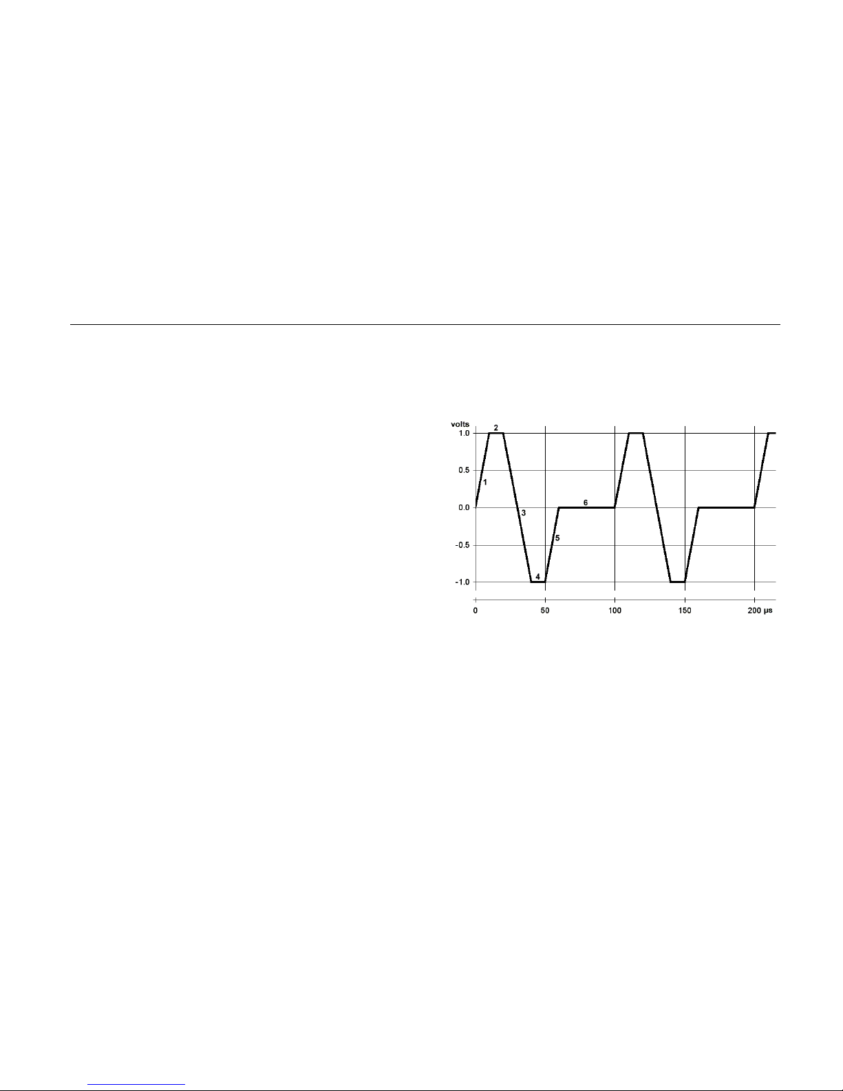
In this exercise we will create a simple waveform as
shown below:
shy0022f.gif
The waveform has 6 segments numbered 1 to 6 over a
period of 100 µs. The segments start and end at multiples
of 10 µs.
First, make sure the Compact Flash card is in its slot.
Then press the
CREATE key.
27
Page 38
291, 292, 294
Getting Started Manual
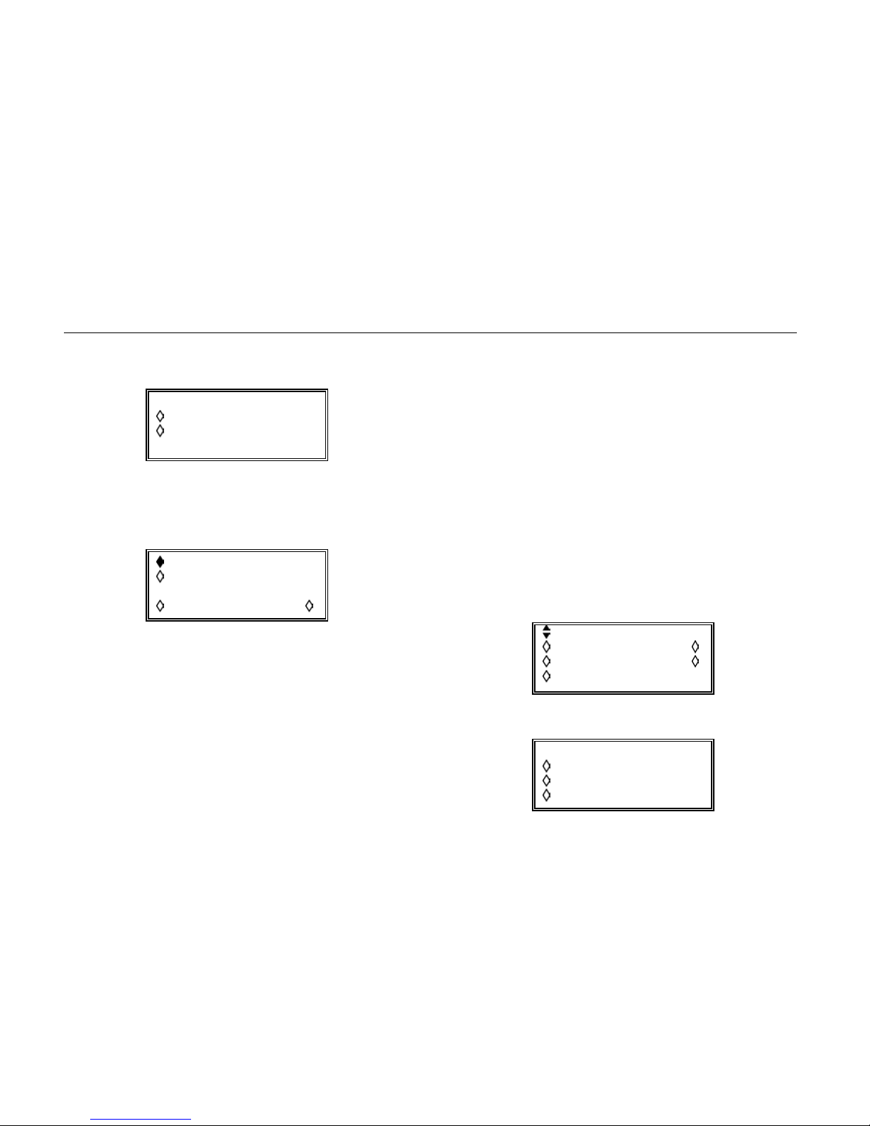
You should see this screen:
CREATE NEW WAVEFORM
create blank…
create from copy…
Select create blank…
You should see this screen:
create: "WFM1 "
size: 0001024
cancel create
Change the size to 100. This will give a time resolution of
1 µs for the repetition rate of 100 µs.
Change the name to something recognizable, such as
MYWAVE. You can do this by using the cursor keys to
select each letter position in turn, then using the rotary
control to choose the character. (By using only numeric
digits and upper case letters you can ensure the name
complies with the Windows 8.3 filename convention; this
will prevent the creation of additional directory entries
when the card is mounted as a PC volume.)
Select create. Your new waveform will appear in the list
of saved waveforms. This waveform (MYWAVE.WFM)
now exists as a file in the memory card's directory and
contains a series of 100 values, all of which are currently
zero.
Modifying a Waveform
The next step is to begin modifying the data to contain the
shape above. Make sure MYWAVE is selected.
Press the MODIFY soft key.
You should see this screen:
MODIFY: MYWAVE
resize… rename…
delete… info…
edit wfm…
Press the edit wfm… soft key
EDIT FUNCTIONS:
point edit…
line draw…
wave insert…
28
Page 39
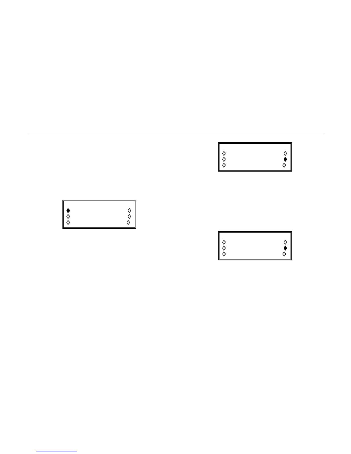
Getting Started
Arbitrary Waveforms
This gives you the ability to edit point-by-point, to draw
straight lines between pairs of points, or to insert other
waveforms between pairs of points:
Press the line draw… soft key
The display initially offers a line covering the entire range
of points from 0 to 99:
LINE (addrs, value)
frm (0000000,0000)
to (0000099,0000)
exit draw line
For the first segment, the addresses are from 0 to 9 and
the corresponding voltages go from zero to 1 V.
To provide some headroom, we'll decide to use a full-scale
range of -2 V to +2 V, so 1 volt is represented by a value
of +1024 (full-scale being +2047).
Set the screen as shown here, using the soft keys to
select the to row and the numeric keypad to enter the
value pair (9,1024).
LINE (addrs, value)
frm (0000000,0000)
to (0000009,1024)
exit draw line
Don't forget to press ENTER after each numeric entry.
Pressing the draw line soft key will complete segment
1 of MYWAVE.
The same screen will reappear, so that the values for
segment 2 can be entered. (It's best to set the to
address before the frm address.)
LINE (addrs, value)
frm (0000010,1024)
to (0000019,1024)
exit draw line
After you have done that, press the draw line soft key
again.
Continue doing this until you have entered segment 5
(there is no need to enter segment 6 because all the
values are zero). The segment 5 screen looks like this:
29
Page 40
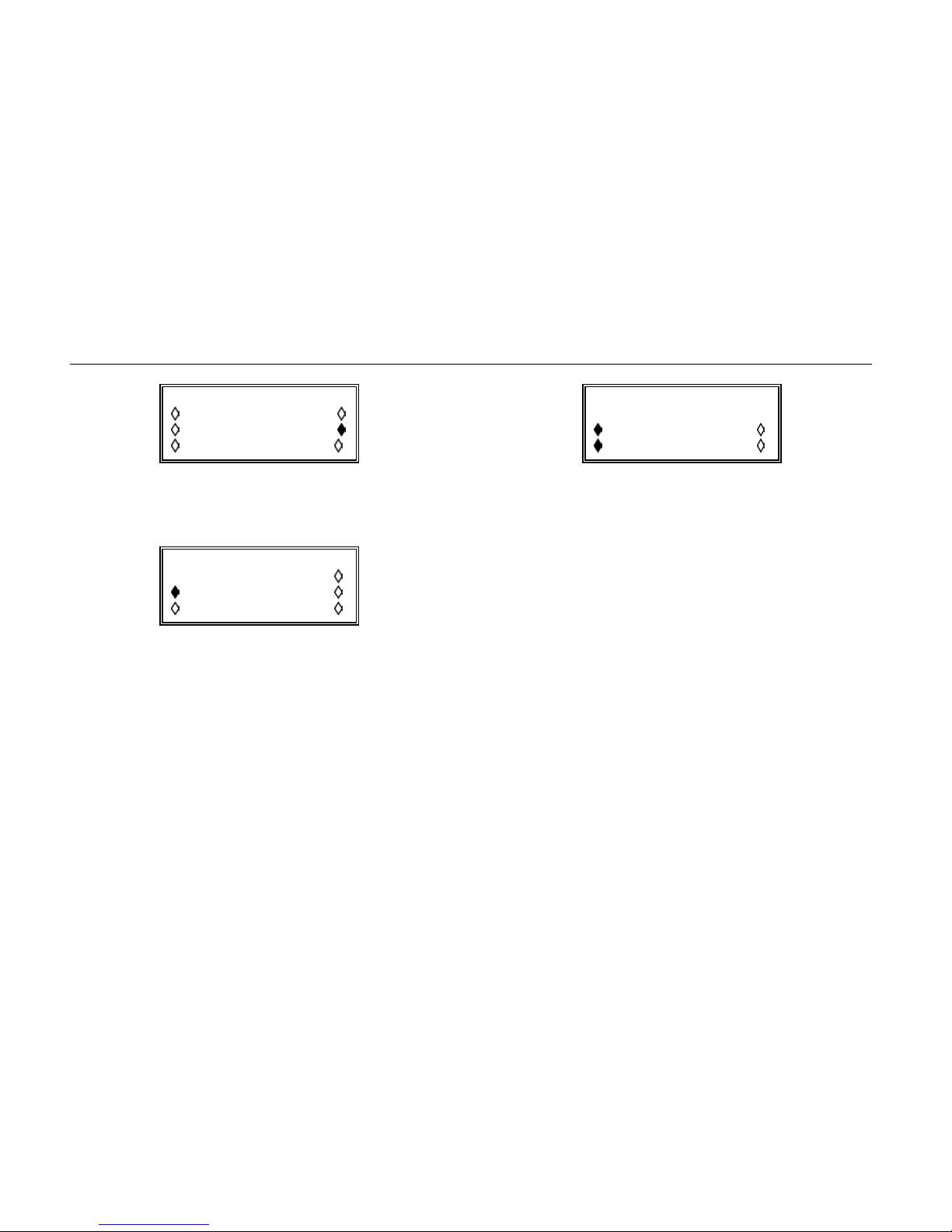
291, 292, 294
Getting Started Manual
LINE (addrs, value)
frm (0000050,1024)
to (0000059,0000)
exit draw line
You can see how the interpolations have been calculated
by stepping through the waveform using the point
edit… screen:
POINT EDIT
(addrs , value)
(0000035,-0593)
exit next point
Congratulations - you have now created an arbitrary
waveform.
Setting the Repetition Rate
The next step is to set up the repetition frequency.
Press the
This time, the display shows the frequency of the arbitrary
waveform, initially in terms of the sample rate. Set this to
1 MHz:
FREQ key.
ARB FREQUENCY: int
1.0000000 MHz
sample waveform
freq period
The solid diamonds indicate that the display is in fact the
sample frequency.
You can select period, which will change the display to
the sample period (1.000 µs), and you can select
waveform, which will change the display to show the
waveform repetition period (100.0 µs). If you then select
freq again you will see the waveform repetition
frequency, 10 kHz.
You might wish to experiment with the wave insert…
function to see how arbitrary waveforms can be built from
sine waves and other shapes.
30
Page 41

Getting Started
Other Functions
Other Functions
This family of 100 MS/s Arbitrary Waveform Generators
offers many features which are beyond the scope of a
Getting Started Manual.
Topics not mentioned here include the ability to be driven
through GPIB, USB and RS232 interfaces, the ability to
add the outputs of other channels, other generators and
external devices to the output signal, the ability to
modulate the output, the ability to produce complex pulse
trains (where the baseline and height can be controlled
independently) and the internal calibration routines. The
instrument's synchronization and triggering capabilities
provide the means to generate multiple waveforms and
sequences of almost unlimited complexity.
These subjects are covered in detail in the Users Manual.
31
Page 42

291, 292, 294
Getting Started Manual
32
 Loading...