

Page 1
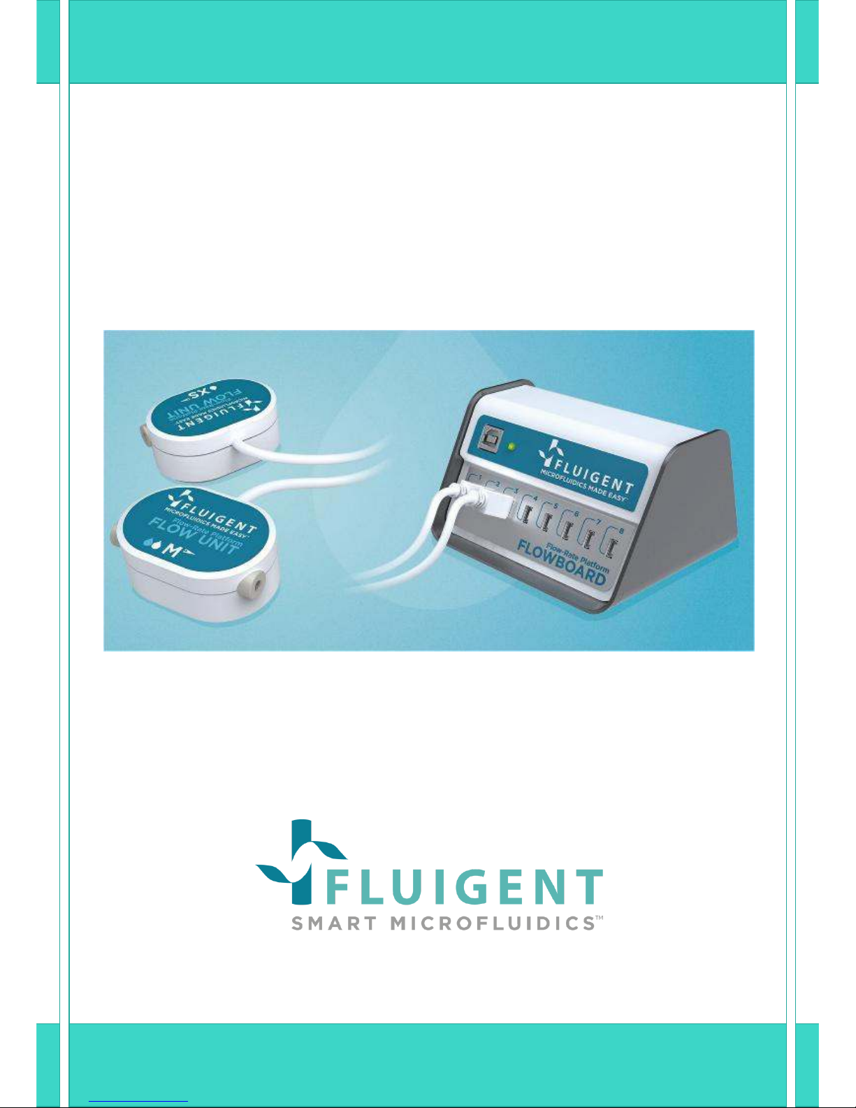
FLOW-RATE PLATFORM
User Manual
FLOW-RATE PLATFORM
Version 6A
Page 2

1. INTRODUCTION ............................................................................................................................ 5
2. GENERAL INFORMATION .............................................................................................................. 6
3. PACKAGE CONTENT ...................................................................................................................... 8
4. FLOW UNIT DESCRIPTION ............................................................................................................. 9
4.1 FLOW UNIT Front and Back .......................................................................................................... 9
4.2 Connection ................................................................................................................................. 11
5. FLOWBOARD DESCRIPTION ........................................................................................................ 14
5.1 Description ................................................................................................................................. 14
5.2 Connection ................................................................................................................................. 15
6. START WORKING WITH THE FLOW-RATE PLATFORM ................................................................. 16
6.1 Quick start procedure ................................................................................................................. 16
6.2 Use at high temperature and high flow-rate .............................................................................. 16
6.3 Use a XL Flow Unit ...................................................................................................................... 16
7. CLEANING PROCEDURE .............................................................................................................. 18
8. DUAL CALIBRATION .................................................................................................................... 20
8.1 Principle of single and dual calibration ....................................................................................... 20
8.2 Example of calibration: FC-40 ..................................................................................................... 20
9. ASSOCIATION WITH OTHER FLUIGENT PRODUCTS...................................................................... 22
9.1 Principle ..................................................................................................................................... 22
9.2 How to connect FLOW UNIT models to Fluiwell.......................................................................... 22
10. FREQUENTLY ASKED QUESTIONS ........................................................................................... 24
11. SPECIFICATIONS ..................................................................................................................... 26
Page 3

Page - 3
FLUIGENT
Siège social : Biopark – 1 mail du Professeur Georges Mathé – 94800 Villejuif – France
Tel : +331 77 01 82 68 – Fax : +331 77 01 82 70
www.fluigent.com
SA à Directoire et Conseil de Surveillance au capital de 141 284.95 € - Siret : 487 636 409 00038 – N°TVA UE/EU VAT Number : FR 53 487 636 409
GUARANTEE TERMS :
What This Warranty Covers
This warranty is granted by Fluigent and applies in all countries.
Your Fluigent product is guaranteed for one year from the date of delivery at your laboratory against defects in
materials and workmanship.
If found to be defective within the warranty period, your Fluigent product will be repaired or replaced free of
charge.
What This Warranty Does Not Cover
This warranty does not cover routine maintenance, or damage resulting from the failure to maintain the
product in accordance with instructions provided by Fluigent. This warranty also does not cover damage that
arises from accidental or intentional misuse or abuse, alteration or customization, or repaired by unauthorized
persons.
How to Get Service
If something goes wrong, contact the Fluigent dealer from whom you purchased your product. Arrange a
mutually convenient time for Fluigent service representative to discuss over the problem and find a solution to
fix the issue. Will be favored any remote repairs, but in case more actions need to be taken, the system will
come back to Fluigent offices (for no additional cost, only if it is under warranty).
The warranty conditions are:
Do never open the FLOWBOARD and the FLOW UNIT devices
Do not use other cables than cables provided by Fluigent
Prevent foreign objects or liquids from entering the FLOWBOARD
Prevent foreign objects from entering the FLOW UNIT
Do not place the product in an unstable location, place the unit in a location with a level surface
and a strong and stable support
Respect the temperature compatibility (from 5°C to 50 °C)
Filter your solution, if possible add a filter in the fluidic path (§ 10) and clean your FLOW UNIT
after each use, especially the FLOW UNIT XS (cf § 4.3). The diameter of the FLOW UNIT XS capillary is
small: 25 µm. Fluigent rejects any liability in the event of clogging or surface modifications.
Do not allow the FLOW UNIT to dry with media in the capillary tube without flushing clean first.
Fluigent advises to realise a cleaning procedure after use.
The FLOW UNIT yellow plugs must be installed for storage
Check the fluid compatibility with the FLOW UNIT wetted materials before using it or ask
Fluigent customer support.
The customer is responsible for fluid used with the FLOW UNIT. Before use, the customer has
to check the compatibility of the fluid with the FLOW UNIT .
For specific use, please contact our Support team at support@fluigent.com
Page 4
Page - 4
FLUIGENT
Siège social : Biopark – 1 mail du Professeur Georges Mathé – 94800 Villejuif – France
Tel : +331 77 01 82 68 – Fax : +331 77 01 82 70
www.fluigent.com
SA à Directoire et Conseil de Surveillance au capital de 141 284.95 € - Siret : 487 636 409 00038 – N°TVA UE/EU VAT Number : FR 53 487 636 409
WARNINGS:
Do never open FLOWBOARD and FLOW UNIT devices. Refer all servicing to after-sales service
department (support@fluigent.com).
Prevent foreign objects or liquids from entering the FLOWBOARD, this may cause a short-circuit
failure or other malfunction. Failing to respect this advice would:
- Expose you to direct current/voltage in case the device is under voltage which may lead to
severe damages
- Void deie’s arrat
- Discharge our company from any liability regarding physical or device damages
Do not place the product in an unstable location, place the device in a location with a level
surface and a strong and stable support.
The diameter of the Flow Unit XS capillary is small: 25 µm. Filter your solution, if possible add
a filter in the fluidic path (§ 10) and clean the Flow Unit XS after each use (cf § 4.3).
Page 5

Page - 5
FLUIGENT
Siège social : Biopark – 1 mail du Professeur Georges Mathé – 94800 Villejuif – France
Tel : +331 77 01 82 68 – Fax : +331 77 01 82 70
www.fluigent.com
SA à Directoire et Conseil de Surveillance au capital de 141 284.95 € - Siret : 487 636 409 00038 – N°TVA UE/EU VAT Number : FR 53 487 636 409
1. Introduction
The new Flow-Rate Platform provides a solution for measuring and/or controlling1 flow-rates for any fluidic
applications. Combining the FLOW UNIT models and the FLOWBOARD will give you the opportunity to check at
all times flow-rate and volume of liquids flowing through your fluidic system. The five (5) different FLOW UNIT
models offer an extensive choice of flow-rate ranges to best match your required precision, from 8 nL/min to 5
mL/min. Beside water based solutions, a second calibration for hydrocarbons is available on three (3) different
FLOW UNIT models (S, M and L), see §8.
This user manual will show you how to install and use the Flow-Rate Platform for your daily work. It will
describe all the Flow-Rate Platform functionalities and will help you to connect all the different FLOW UNIT
models and the FLOWBOARD, and to use it with all the equipment.
1
with Fluigent MFCSTM-EZ (and MFCSTM), the Flow-Rate Control Module and a specific dongle.
Page 6
Page - 6
FLUIGENT
Siège social : Biopark – 1 mail du Professeur Georges Mathé – 94800 Villejuif – France
Tel : +331 77 01 82 68 – Fax : +331 77 01 82 70
www.fluigent.com
SA à Directoire et Conseil de Surveillance au capital de 141 284.95 € - Siret : 487 636 409 00038 – N°TVA UE/EU VAT Number : FR 53 487 636 409
2. General information
The Flow-Rate Platform enables flow-rate measurements, in a wide range of flow-rates thanks to the five (5)
models: XS, S, M, L and XL.
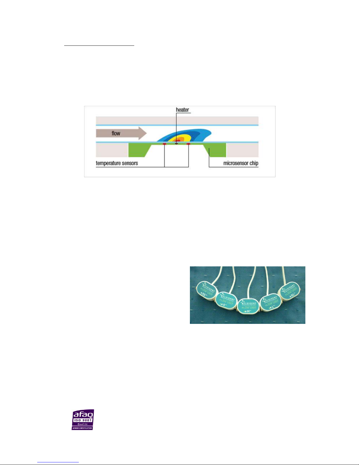
The flow-rate acquisition is based on a thermal technology. A heating element on the microchip adds a minimal
amount of heat to the medium for the thermal flow measurement. Two temperature sensors, symmetrically
located above and below the source of the heat, detect even the slightest temperature differences, thus
providing the basic information about the spread of the heat, which itself is directly related to the flow -rate.
It is possible to use the Flow-Rate Platform with any flow control systems, from pressure controllers to other
types of flow controllers, provided that the flow-rate applied to a FLOW UNIT does not go beyond its range.
The Flow-Rate Platform enables you to measure the flow-rate and the volume of fluid introduced during your
experiment.
Five (5) different FLOW UNIT models are available. They depend on flow-rate ranges and calibration.
Here is a picture of the five (5) FLOW UNIT models
with different ranges, among which three (3)
models with a dual calibration (S, M and L models).
All the fluidic specifications are diplayed in the
table below .
Note: The Flow-Rate Platform can work at its best performances with FLUIGENT pressure flow control solutions
MFC“™ ad MFC“™-EZ). More details on
www.fluigent.com.
Page 7

Page - 7
FLUIGENT
Siège social : Biopark – 1 mail du Professeur Georges Mathé – 94800 Villejuif – France
Tel : +331 77 01 82 68 – Fax : +331 77 01 82 70
www.fluigent.com
SA à Directoire et Conseil de Surveillance au capital de 141 284.95 € - Siret : 487 636 409 00038 – N°TVA UE/EU VAT Number : FR 53 487 636 409
FLOW UNIT
XS S M L XL
Sensor
inner
diameter
25 µm
150 µm
430 µm
1.0 mm
1.8 mm
Maximum
pressure
200 bar
200 bar
100 bar
12 bar
5 bar
Wetted
materials
PEEK and Quartz
Glass
PEEK and Quartz
Glass
PEEK and
Borosilicate Glass
PEEK and
Borosilicate Glass
PEEK and
Borosilicate
Glass
Calibrated
Media
Water
Water
Isopropyl Alcohol
Water
Isopropyl Alcohol
Water
Isopropyl Alcohol
Water
Range
0±1.5 µL/min
0±7 µL/min
0±70 µL/min
0±80 µL/min
0±500 µL/min
0±1 mL/min
0±10 mL/min
0±5mL/min
Accuracy
(m.v =
measured
value)
10% m.v. above
75 nL/min
5% m.v.above 0.42
µL/min
20% m.v. above 4.2
µL/min
5% m.v. above 2.4
µL/min
20% m.v above 25
µL/min
5% m.v. above
0.04 mL/min
20% m.v above 0.5
mL/min
5% m.v.above
0.2 mL/min
7.5 nL/min below
75 nL/min
21 nL/min below
0.42 µL/min
210 nL/min below
4.2 µL/min
0.12 µL/min below
2.4 µL/min
5 µL/min below 25
µL/min
1.5 µL/min below
0.04 mL/min
100 µL /min below
0.5 mL/min
10 µL/min below
0.2 mL/min
Lowest
detectable flow
increment
3.7 nL/min
10 nL/min
0.06 µL/min
0.7 µL/min
3 µL/min
Warning:
Please note that the maximum pressure depends on the FLOW UNIT model. Ensure that the
pressure applied to a FLOW UNIT does not go beyond this value at all times.
The Flow-Rate Platform suits your own fluid controller. If you use a pressure regulator you may have to enter
a maximum pressure below this value. If you use other flow controller, be aware that pressure may go
higher than 100 bar very easily and may cause damage to your FLOW UNIT.
Page 8
Page - 8
FLUIGENT
Siège social : Biopark – 1 mail du Professeur Georges Mathé – 94800 Villejuif – France
Tel : +331 77 01 82 68 – Fax : +331 77 01 82 70
www.fluigent.com
SA à Directoire et Conseil de Surveillance au capital de 141 284.95 € - Siret : 487 636 409 00038 – N°TVA UE/EU VAT Number : FR 53 487 636 409
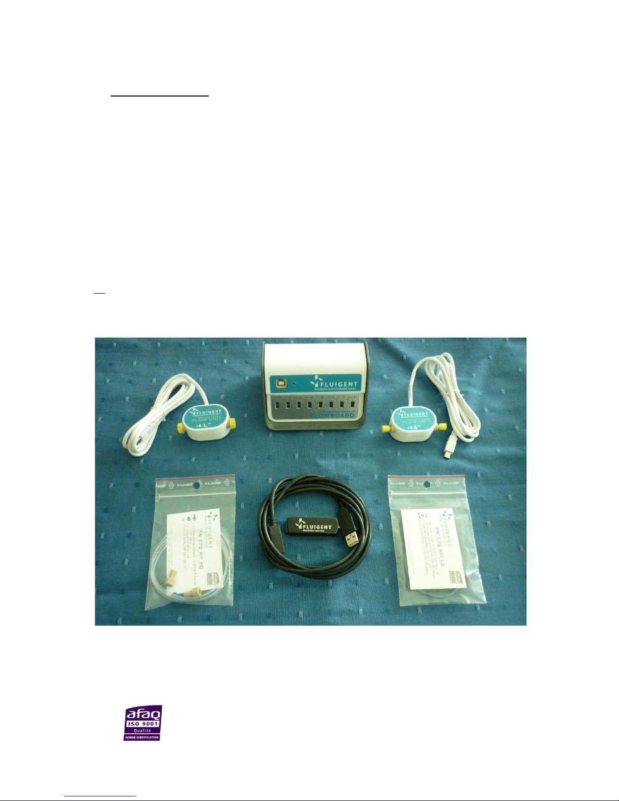
3. Package content
The Flow-Rate Platform package contains the following items:
One FLOWBOARD
At least one FLOW UNIT and its yellow plugs for storage
A USB cable
A connection kit:
-With the XS, S and M FLOW UNIT models, the Flow-Rate Platform package can contain (not always
included) one kit CTQ_KIT_LQ : To LQ flo uit oetor for /’’OD tuig, one meter of PEEK Tubing Blue
/’’ OD .’’ ID, 1 green sleeve /6’’ OD * .’’*.6, adapter PEEK /6’’ to /’’ OD tubing (cf
§9.2, ).
-With the L and XL FLOW UNIT models, the Flow-Rate Platform package can contain (not always
included) one kit CTQ_KIT_HQ:
Two Flow Unit HQ connector ¼-8 Flat Botto for /’’ OD tuig, ferrules
for HQ flo uit, FEP tuig /’’ OD * .’’ID.
NB
: With the XL Flow Unit model, 15 cm of /’’ OD PEEK tubing with 1.4 mm ID is added (cf §8).
FLUIGENT Software Platform in a USB stick
This user manual
If any part is missing or damaged, please contact your local dealer or FLUIGENT immediately
(support@fluigent.com).
Page 9
Page - 9
FLUIGENT
Siège social : Biopark – 1 mail du Professeur Georges Mathé – 94800 Villejuif – France
Tel : +331 77 01 82 68 – Fax : +331 77 01 82 70
www.fluigent.com
SA à Directoire et Conseil de Surveillance au capital de 141 284.95 € - Siret : 487 636 409 00038 – N°TVA UE/EU VAT Number : FR 53 487 636 409
4. FLOW UNIT Description
4.1 FLOW UNIT Front and Back
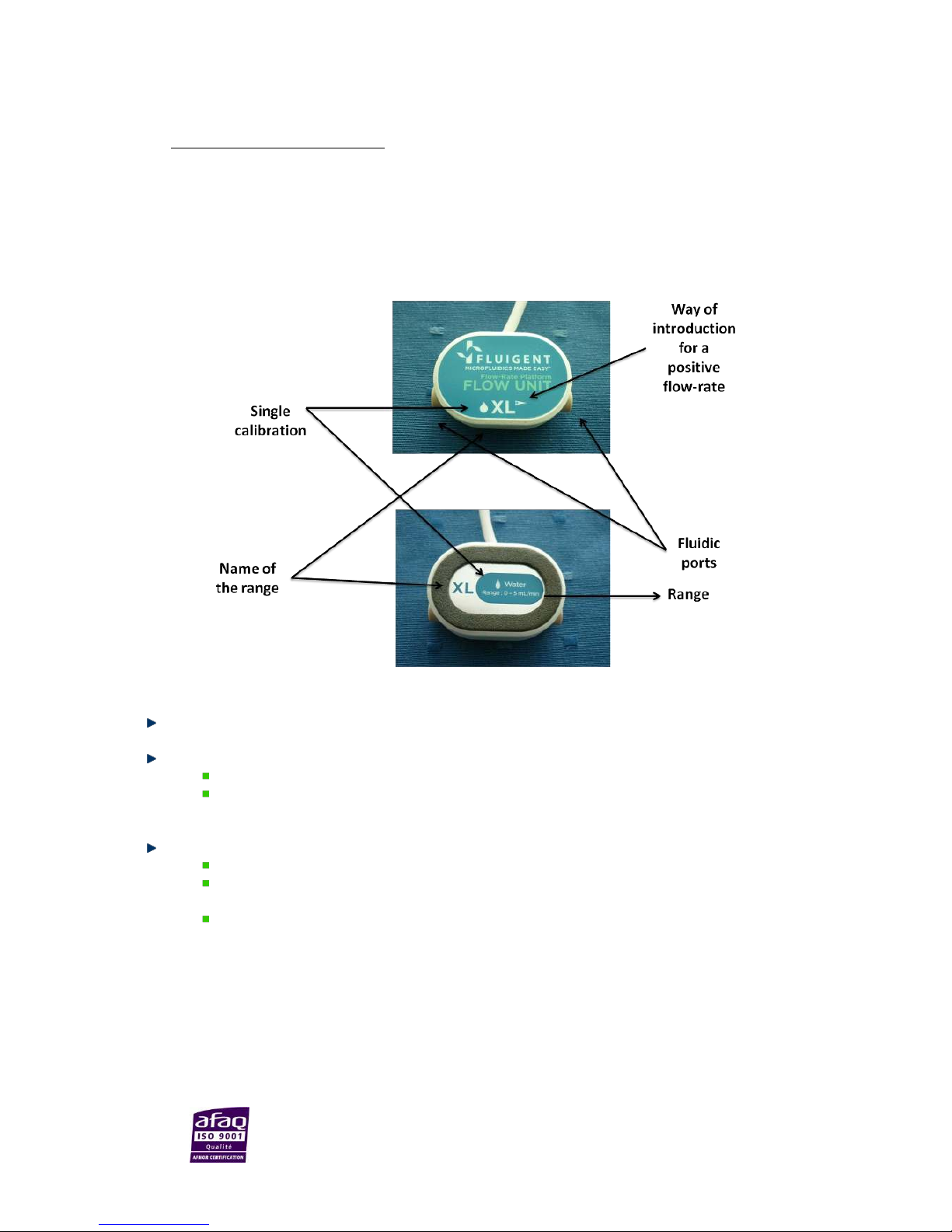
XS, XL FLOW UNIT models
The two (2) fluidic ports are on the sides of the device.
The front of the FLOW UNIT displays information about the range and the calibration:
The letter idiates the odel; Here it’s XL.
The droplet indicates the calibration. Here there is a single white droplet. It indicates that the
sensor is calibrated for water (cf §2).
The back of the FLOW UNIT also displays information about the range and the calibration:
The letter indicates the odel; Here it’s XL.
The droplet indicates the calibration. Here there is a single white droplet: it indicates that the
sensor is calibrated for water.
The range is displayed clearly: 0 ± 5.0 mL/min.
Page 10

Page - 10
FLUIGENT
Siège social : Biopark – 1 mail du Professeur Georges Mathé – 94800 Villejuif – France
Tel : +331 77 01 82 68 – Fax : +331 77 01 82 70
www.fluigent.com
SA à Directoire et Conseil de Surveillance au capital de 141 284.95 € - Siret : 487 636 409 00038 – N°TVA UE/EU VAT Number : FR 53 487 636 409
S, M, L FLOW UNIT models
The two (2) fluidic ports are on the sides of the device.
The front of the FLOW UNIT displays information about the range and the calibration:
The letter indicates the odel; here it’s L.
The droplets indicate the calibration. Here there are two droplets: a blue one and a white one. It
indicates that the sensor has dual calibration, one for water and the other one for isopropyl
alcohol (cf § 2).
The back of the FLOW UNIT also displays information about the range and the calibration:
The letter indicates the name of the model; here it’s L.
The droplets indicate the calibration. Here there are two (2) droplets: a blue one and a white one..
It indicates that the sensor is calibrated for water and isopropyl alcohol.
The range is displayed clearly:
o 0 ± 1000µL/min for water
o 0 ± 10mL/min for isopropyl alcohol
Positive
flow-rate
direction
Dual Calibration
(Water/isopropyl
alcohol)
Page 11

Page - 11
FLUIGENT
Siège social : Biopark – 1 mail du Professeur Georges Mathé – 94800 Villejuif – France
Tel : +331 77 01 82 68 – Fax : +331 77 01 82 70
www.fluigent.com
SA à Directoire et Conseil de Surveillance au capital de 141 284.95 € - Siret : 487 636 409 00038 – N°TVA UE/EU VAT Number : FR 53 487 636 409
4.2 Connection
4.2.1 Fluidic connection for XS, S and M FLOW UNIT models
The XS, S and M FLOW UNIT models have two (2) fluidic ports.
The characteristics of those two (2) ports are:
Thread-size: UNF 6-40.
Compatible with tubings of /’’ eteral diaeter
(1/32’’ OD.
To get started, FLUIGENT can provide you a CTQ_KIT_LQ
kit including:
One gree sleee /’’ OD x .’’.
Two (2) LQ flo uit oetor for /’’OD tuig,
One (1) eter of PEEK Tuig Blue /’’ OD .’’
ID
Oe adapter PEEK /’’ to /’’ OD tuig
NB: As there is a wide variety of tubings and fittings for the different applications that you may use, FLUIGENT
advises you to make sure that your fluidic connection system fits with the two (2) fluidic ports of the FLOW
UNIT. If not, please note that there is a large panel of adapters and unions to connect your tubings to ours. Visit
www.fluigent.com to learn more about materials and ID aailale ith /’’ or / OD tubing, nuts and
ferrules from fittings suppliers to suit your application.
4.2.2 Fluidic connection for L and XL FLOW UNIT models
The L and XL FLOW UNIT models have two fluidic ports.
The characteristics of those two (2) ports are:
Thread-size: ¼-28.
Flat-bottom type (FB).
Compatible with tubings of /’’ eteral diaeter
(1/16’’ OD.
To get started, FLUIGENT can provide you the CTQ_KIT_HQ
kit including:
Two (2) Flow Unit HQ connector ¼-28 Flat Bottom for
/’’ OD tuig
Four (4) ferrules for HQ flow unit
1 m FEP tubig /’’ OD * .’’ID.
NB 1 : Fiftee etieters of /’’ OD PEEK tuig ith
1.40 mm ID is including with the XL Flow Unit model (cf §8).
Page 12

Page - 12
FLUIGENT
Siège social : Biopark – 1 mail du Professeur Georges Mathé – 94800 Villejuif – France
Tel : +331 77 01 82 68 – Fax : +331 77 01 82 70
www.fluigent.com
SA à Directoire et Conseil de Surveillance au capital de 141 284.95 € - Siret : 487 636 409 00038 – N°TVA UE/EU VAT Number : FR 53 487 636 409
NB 2 : As there is a wide variety of tubings and fittings for the different applications that you may use,
FLUIGENT advises you to make sure that your fluidic connection system fits with the two (2) fluidic ports of the
FLOW UNIT. If not, please note that there is a large panel of adapters and unions to connect your tubings to
ours. Visit
www.fluigent.com to learn more about materials and ID aailale ith /’’ or / OD tubing,
nuts and ferrules from fittings suppliers to suit your application.
4.2.3 How to connect tubing to the FLOW UNIT models
The pictures below illustrate how to connect OD /’’ tuig to L ad XL FLOW UNIT odels.
1. Cut the /’’ OD tuig to the desired length, leaving a square-cut face.
2. Slide the nut over the tubing with the nut thread facing the tubing end being connected.
3. Slip the ferrule over the tubing, with the tapered portion of the ferrule facing the nut. NB: the nuts and
ferrules are specifically designed to work together. FLUIGENT advises you to only associate the provided
ferrules with the provided nuts and vice-versa.
4. Insert the assembly into the receiving port, and while holding the tubing firmly against the bottom of the
port, tighten the nut finger tight.
5. To check the tightness of your connection, you may pull gently on the tubing: it must stay fitted in the
ferrule and nut.
6. Do the same thing on the 2nd port.
Page 13
Page - 13
FLUIGENT
Siège social : Biopark – 1 mail du Professeur Georges Mathé – 94800 Villejuif – France
Tel : +331 77 01 82 68 – Fax : +331 77 01 82 70
www.fluigent.com
SA à Directoire et Conseil de Surveillance au capital de 141 284.95 € - Siret : 487 636 409 00038 – N°TVA UE/EU VAT Number : FR 53 487 636 409
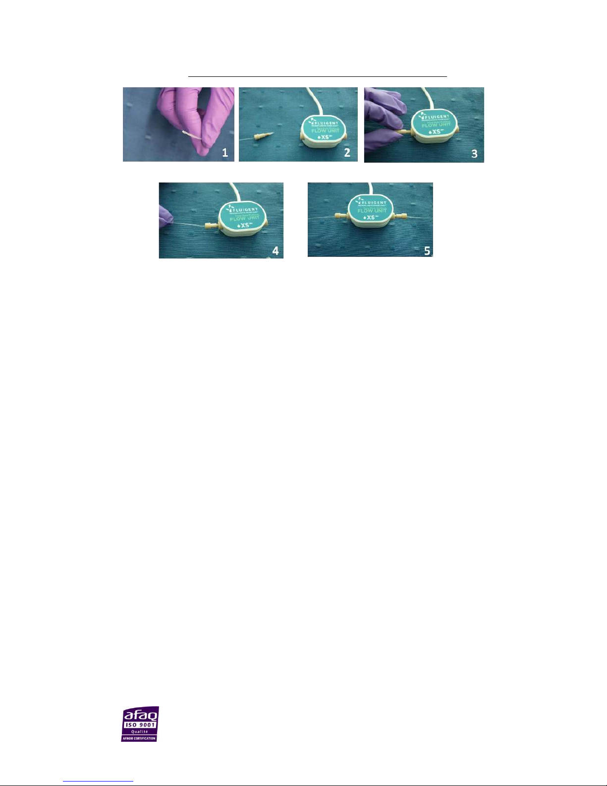
The pictures below show ho to oet OD /’’ tuig to X“, “ ad M FLOW UNIT odels.
1. Cut the 1/32’’ OD tuig to the desired length, leaving a square-cut face.
2. Slide the fitting over the tubing.
3. Insert the assembly into the receiving port, and while holding the tubing firmly against the bottom of
the port, tighten the fitting finger tight.
4. To check the tightness of your connection, you may pull gently on the tubing: it must stay fitted in the
ferrule and nut.
5. Do the same thing on the 2nd port.
Page 14
Page - 14
FLUIGENT
Siège social : Biopark – 1 mail du Professeur Georges Mathé – 94800 Villejuif – France
Tel : +331 77 01 82 68 – Fax : +331 77 01 82 70
www.fluigent.com
SA à Directoire et Conseil de Surveillance au capital de 141 284.95 € - Siret : 487 636 409 00038 – N°TVA UE/EU VAT Number : FR 53 487 636 409
5. FLOWBOARD Description
The FLOWBOARD is absolutely necessary to operate the Flow-Rate Platform. This device hosts up to eight (8)
FLOW UNIT models and provides them power supply. The FLOWBOARD is also the link between the connected
FLOW UNIT models and the software (cf. Flow-Rate Platform
Soft Front Panel User Manual or MaesfloTM User
Manual).
When using the Flow-Rate Platform alone, one must use the Flow-Rate Platform Soft Front Panel (FRP-SFP).
When combining the Flow-Rate Platform with the MFCSTM-EZ, one must use the MaesfloTM.
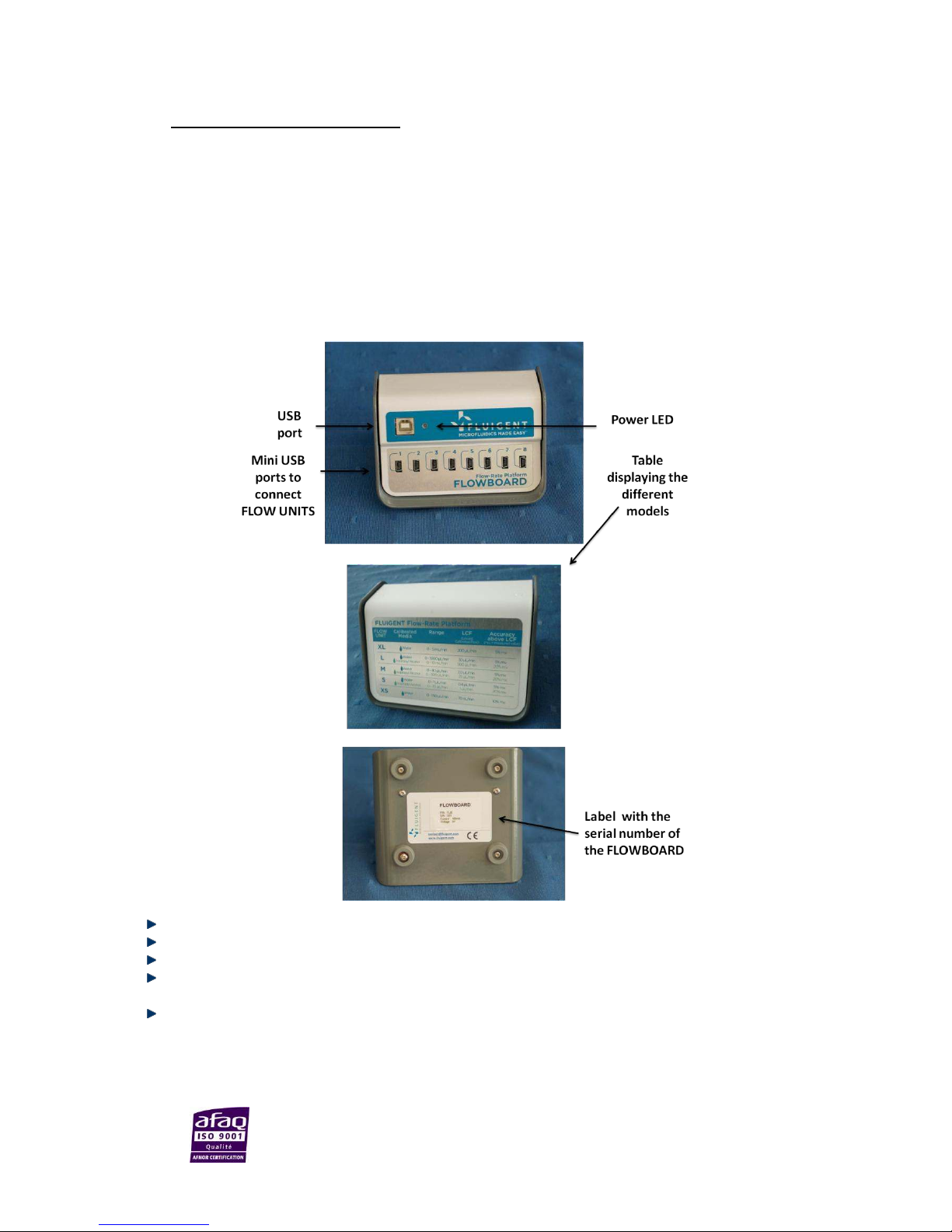
5.1 Description
A green indicator (power LED) lights up when the FLOWBOARD is connected.
A USB port (type B) links the FLOWBOARD to a computer for software control.
There are eight (8) mini USB ports (to connect up to eight (8) FLOW UNIT devices).
On the back of the FLOWBOARD a table summarizes all the FLOW UNIT models available and their
characteristics.
On the bottom of the FLOWBOARD a label indicates the product number, the serial number, the current
and the voltage.
Page 15

Page - 15
FLUIGENT
Siège social : Biopark – 1 mail du Professeur Georges Mathé – 94800 Villejuif – France
Tel : +331 77 01 82 68 – Fax : +331 77 01 82 70
www.fluigent.com
SA à Directoire et Conseil de Surveillance au capital de 141 284.95 € - Siret : 487 636 409 00038 – N°TVA UE/EU VAT Number : FR 53 487 636 409
5.2 Connection
5.2.1 USB connection
Connect the type B plug of the USB cable
provided with the Flow-Rate Platform into
the type B USB port on the front of the
FLOWBOARD.
Connect the other end of the USB cable
(type A standard plug) to the computer
where the corresponding software is
installed (cf. User Manual).
5.2.2 FLOW UNIT connection
To connect a FLOW UNIT to the FLOWBOARD,
plug the end of the mini-USB plug fixed with
the FLOW UNIT to one of the eight (8) mini-USB
ports on the FLOWBOARD.
Page 16

Page - 16
FLUIGENT
Siège social : Biopark – 1 mail du Professeur Georges Mathé – 94800 Villejuif – France
Tel : +331 77 01 82 68 – Fax : +331 77 01 82 70
www.fluigent.com
SA à Directoire et Conseil de Surveillance au capital de 141 284.95 € - Siret : 487 636 409 00038 – N°TVA UE/EU VAT Number : FR 53 487 636 409
6. Start working with the Flow-Rate Platform
6.1 Quick start procedure
Here is a quick setup guide to remind you the main steps to get your Flow-Rate Platform up and running.
1. First, you may want to integrate the different FLOW UNIT to your microfluidic system, with the right
fittings. See §4.2 how to do it.
2. Then, connect the FLOW UNIT models to the FLOWBOARD. See §5.2 how to do it.
3. Then connect the FLOWBOARD and the computer with the USB cable. See §5.2 how to do it.
4. To finish start the software (FRP SFP or MAESFLO) installed on your computer (user manual)
You can now use your Flow-Rate Platform for your application.
DO NOT FORGET TO CLEAN AND RINSE YOUR FLOW UNIT AFTER USE (See §7 how to do it.)
6.2 Use at high temperature and high flow-rate
The Flow Units can be used in a large range of temperature, but some elements need to be taken into account:
- The Flow Units include temperature compensation between 10°C and 50°C. However, as the
temperature deviates from 20°C, the absolute accuracy may acquire an additional error of
typically 0.1% of the measured flow rate per °C.
For example the L Flow Unit model at 50°C has a specified error of 5% + 30*0.1% = 8% of the
measured value.
- Between 50°C and 80°C the Flow Unit will still be operational and the repeatability will still be
excellent. However, we give no more guarantee for the absolute accuracy of the calibration.
In order to get a correct reading from the sensor, it is crucial to have the liquid temperature and ambient
temperature the same (within ± 3°C). At low flow rates this o’t e a problem, because the liquid adapts to
the ambient temperature very quickly. At higher flow rates (for L and XL Flow Unit models) this is important.
6.3 Use a XL Flow Unit
The oiatio of differet paraeters a lead to uated ehaiors ad surprisig easureets. It’s
related to the formation of localized vortex and arise from a combination of the following facts:
- The decreased viscosity of liquid at elevated temperatures (for example for water at 40°C the viscosity
is about half the one at 20°C)
- The combination of small ID tubing (for example 500 µm ID tubing) with the 1.8 mm ID sensor.
The transition from the small ID tube to the larger ID sensor may lead to a jet at high flow speeds and low
viscosity, see the following sketch. Such a jet is inherently unstable, which can lead to strong fluctuations at
high flow-rates and temperatures. The phenomenon is also strongly dependent on the exact geometry of the
arrangement. A bending of the tube on the inlet side may generate a stationary vortex and the fluid in
proximity to the sensor chip may actually be flowing backward, see the next sketch:
Page 17

Page - 17
FLUIGENT
Siège social : Biopark – 1 mail du Professeur Georges Mathé – 94800 Villejuif – France
Tel : +331 77 01 82 68 – Fax : +331 77 01 82 70
www.fluigent.com
SA à Directoire et Conseil de Surveillance au capital de 141 284.95 € - Siret : 487 636 409 00038 – N°TVA UE/EU VAT Number : FR 53 487 636 409
This can lead to a negative flow reading.
To solve this observed behavior, Fluigent advises you to use 1 of 1/1’’OD 1 ID tuig, before the
sensor, provided with the Flow-Rate Platform package that contains XL flow unit model. Pay attention when
you cut the tube to leave a square-cut face.
Page 18

Page - 18
FLUIGENT
Siège social : Biopark – 1 mail du Professeur Georges Mathé – 94800 Villejuif – France
Tel : +331 77 01 82 68 – Fax : +331 77 01 82 70
www.fluigent.com
SA à Directoire et Conseil de Surveillance au capital de 141 284.95 € - Siret : 487 636 409 00038 – N°TVA UE/EU VAT Number : FR 53 487 636 409
7. Cleaning procedure
Flow Unit models are highly sensitive and should be properly cleaned to always maintain high performance.
With proper care and maintenance, the Flow Units can last many years. No cleaning or improper cleaning may
leave deposits on the internal capillary wall which could result in measurement deviations and even clogging.
Cleaning the sensor after use and before storing the device for a long period of time should prevent the
sensors from any damage.
7.1.1 Explanation
Inside the liquid flow sensors, the sensor chip measures the flow through the wall of a thin walled glass
capillary. Because the measurement uses the heat propagation through the glass wall and the heat exchange
with the medium, it is critical that the coupling of the chip with the medium is not altered. Formation of
deposits on the glass wall inside the capillary may block the heat transfer.
7.1.2 General Handling
Do not allow the sensor to dry with media in the capillary tube without flushing clean first. Also try to avoid
letting the filled sensor sit for extended periods (depending on your liquid).
Before storing the sensor, always drain of fluid, flush with cleaning agent, blow out, and dry the capillary.
For the XS FLOW UNIT model, filter your solution through a 5µm (or lower) membrane filter.
7.1.3 Cleaning Procedure
Cleaning and flushing of the Flow Units should consider the nature of the materials that were being pumped
through them. Typically, one should select a cleaning solution that is safe for the Flow Unit (the inside surface)
and the rest of the set up yet will dissolve the type of samples that were in contact with the surface.
For Flow Unit XS, S and M, fluids have to be compatible with PEEK & Quartz glass.
For Flow Unit L and XL, fluids have to be compatible with PEEK & Borosilicate glass.
The following steps are recommended for water-based solutions, in the right order:
Rinse all your system with water
Clean the Flow Unit with a non-foaming detergent.
The detergent needs to be compatible with Flow Unit, the rest of your set-up (microfluidic chip,
especially) and fluids used before during your experiment.
Remove all the contaminant thanks to a disinfectant (for example, Javel bleach).
Rinse the Javel bleach (or the selected disinfectant) with water.
Rise all ou sste ith isopropaol. Thaks to this fial step, ou o’t leae a trae o our
Flow Unit.
Then, sensor yellow plugs must be installed for storage.
Page 19

Page - 19
FLUIGENT
Siège social : Biopark – 1 mail du Professeur Georges Mathé – 94800 Villejuif – France
Tel : +331 77 01 82 68 – Fax : +331 77 01 82 70
www.fluigent.com
SA à Directoire et Conseil de Surveillance au capital de 141 284.95 € - Siret : 487 636 409 00038 – N°TVA UE/EU VAT Number : FR 53 487 636 409
7.1.4 Recommendations for fluids
Working with Multiple Liquids
Switching between multiple liquids can leave transient deposits in the form of liquid layers inside the glass
capillary. This is especially common for insoluble liquids, but can happen even with miscible liquid
combinations. For example, when IPA is followed by water in a sensor without drying in between, large offsets
can be observed for hours after switching to water.
If possible, dedicate a separate sensor for each different liquid to be measured. If not possible, use caution
when switching media and clean properly.
Working with Water
When working with water it is recommended not to let the sensor dry out. All salts and minerals in the water
will deposit on the glass and are difficult to remove. Although salt solutions are particularly prone to problems,
even clean water can still contain enough dissolved minerals to form a deposition layer. Flush with DI water on
a regular basis to prevent build-up. If you still encounter problems, occasionally flush the sensor with slightly
acidic cleaning agents.
When working with water containing organic materials (sugars, etc.) microorganisms often grow on the walls
of the glass capillary and form an organic film that can be difficult to remove. Flush on a regular basis with
solvents such as ethanol, methanol or IPA, or with cleaning detergents to remove organic films.
Working with Silicone Oils
When working with silicone oil it is recommended not to let the sensor dry out. Silicone oils can be cleaned out
using special cleaners. Check with your silicone oil supplier for cleaning agents compatible with glass surfaces.
Working with Paints or Glues
When working with paints or glues it is critical not to let the sensor dry out. Often, depositions of paints and
glues cannot be removed anymore after they have dried. Flush the sensor with cleaning agents recommended
by your paint or glue manufacturer that are compatible with glass. Ensure that you have found a good cleaning
procedure before performing the first tests, and always clean shortly after emptying the sensor.
Working with Alcohols or Solvents
Unlike most other fluids, alcohols and solvents are not critical and a short flush of isopropanol (IPA) is sufficient
to clean the capillary walls.
Other Liquids or Applications
If uncertain about your application and how to clean the flow sensor, please contact FLUIGENT for additional
support at
support@fluigent.com .
Identified cleaning solutions
Sample liquid
Cleaning solution
Supplier
Biofilm/cells
Biofilm remover
Sodium dichloroisocyanurate (1
ppm HClO; ref : 218928)
Umweltanalytik
Sigma Aldrich
1% micro-beads of
polystyrene in DI Water
Toluene 99.8% (ref : 244511)
Sigma Aldrich
Mineral oil (Sigma cat no.
5904)
RBS 25 (ref : 83460)
Sigma Aldrich
Blood
BD FACS Clean
RBS 25 (ref : 83460)
BD
Sigma Aldrich
Page 20

Page - 20
FLUIGENT
Siège social : Biopark – 1 mail du Professeur Georges Mathé – 94800 Villejuif – France
Tel : +331 77 01 82 68 – Fax : +331 77 01 82 70
www.fluigent.com
SA à Directoire et Conseil de Surveillance au capital de 141 284.95 € - Siret : 487 636 409 00038 – N°TVA UE/EU VAT Number : FR 53 487 636 409
7.1.5 Cleaning Methods that are not recommended
In general, any cleaning by mechanical means should be avoided. Never eter the sesor’s flo path ith
sharp objects that could scratch the glass surface.
Furthermore, no abrasives or liquids containing solids that can grind the surface clean should be used. Anything
that affects the glass wall will cause deviations in the measurement performance or permanently damage the
sensor.
Strong acids and bases should also not be used to clean the sensor . Acids can sometimes be used in low
concentration and at low temperatures. Before using the acid check how compatible it is with borosilicate 3.3
glass (Pyrex® or Duran®).
.
8. Dual calibration
8.1 Principle of single and dual calibration
The different FLOW UNIT models are calibrated to provide an accurate reading when used with the
corresponding fluid, water or isopropyl alcohol.
For the FLOW UNIT models XS/XL, only one single calibration for water is available. For the FLOW UNIT models
S/M/L, two calibrations are available: Water and Isopropyl alcohol.
The FLOW UNIT can be used to handle different fluids not originally calibrated for. When possible, select a
standard calibration field that most closely matches your fluid. For example, water calibration can be used for
water based solution and isopropyl alcohol calibration for hydrocarbons or oil. The calibration can be selected
and switched in the software (see the corresponding user manual).
In order to obtain accurate flow-rates for alternative fluids, it is necessary to use correction factors (scale
factor), to convert the displayed value into the actual value. The scale factor can be added in the software (see
Custom scale factor in the corresponding user manual). Adding the scale factor ensures that the flow sensor
reading is now accurate for the target fluid.
The following section explains how you can calculate this scale factor and shows an example with a fluorinated
oil: FC-40.
8.2 Example of calibration: FC-40
A method for providing a known flow-rate is required to work out the scale factor for the selected fluid. This
could be a syringe pump, a peristaltic pump or a pressure regulator delivering fluid onto a precision balance
with volume calculated from known density.
Here is an example using MFCSTM-EZ, a fast and stable pressure-based flow controller delivered by FLUIGENT.
The aim of this FASTABTM technology is to pressurize a reservoir containing the fluid of interest to be injected
through the microfluidic system. For more information about the MFCSTM-EZ, please visit us at
www.fluigent.com.
Page 21

Page - 21
FLUIGENT
Siège social : Biopark – 1 mail du Professeur Georges Mathé – 94800 Villejuif – France
Tel : +331 77 01 82 68 – Fax : +331 77 01 82 70
www.fluigent.com
SA à Directoire et Conseil de Surveillance au capital de 141 284.95 € - Siret : 487 636 409 00038 – N°TVA UE/EU VAT Number : FR 53 487 636 409
Make a table that contains the time for each measurement, the flow-rate of the pump and the data measured
by the FLOW UNIT. A minimum of 3 measurements is recommended for each flow-rate.
The principle of the experiment is to inject the FC-40 through the desired FLOW UNIT model connected to the
FLOWBOARD. Then simultaneously you record the flow-rate given by the software and you measure the weight
of fluid you have collected over a chosen period of time. Knowing the density of the fluid, you are able to
define the actual flow-rate.
Note that if a peristaltic or a syringe pump is used, one has to wait until the target flow-rate is reached (settling
times can be long) and to calculate an average flow-rate due to the pulsations.
The list of materials needed to reproduce the experiment is given below:
- One (1) FLOWBOARD
- One (1) FLOW UNIT model
- One (1) MFC“™-EZ or with the appropriate pressure range (1 bar for FC- ad Maesflo™.
software (or later versions)
- One (1) precision weighing scale
The table below displays the information recorded during the experiment: the pressure imposed by the
MFC“™-EZ, Qs the flow-rate recorded by the FLOW UNIT through the Flow-Rate Platform software, Qw the
flow-rate measured with the precision weighing scale, and Qw/Qs the calculated scale factor for a single point
calibration.
Pressure (mbar)
QS (µl/min)
Qw (µl/min)
Qw/QS
596.3
91.6
317.8
3.5
Consequently, when working around 317 µl/min (target flow-rate), you have to add the scale factor of 3.5 so
that the measurement of the sensor corresponds to the actual flow-rate for FC-40.
Page 22

Page - 22
FLUIGENT
Siège social : Biopark – 1 mail du Professeur Georges Mathé – 94800 Villejuif – France
Tel : +331 77 01 82 68 – Fax : +331 77 01 82 70
www.fluigent.com
SA à Directoire et Conseil de Surveillance au capital de 141 284.95 € - Siret : 487 636 409 00038 – N°TVA UE/EU VAT Number : FR 53 487 636 409
9. Association with other Fluigent products
9.1 Principle
The assoiatio of the MFC“™ MFC“™ ad MFC“™-EZ) and the Flow-Rate Platform controlled by the Maesflo™
software enables you to measure the flow-rate and the volume of fluid introduced during your experiment.
In association with the Flow-Rate Control Module1 (FRCM) you can even control your flows either with pressure
and/or flow-rate set points. The FRCM first performs an automated characterization of your fluidic system to
ork out the relatioships etee the MFC“™ pressure haels ad the flo-rate channels. This
pressure/flow-rate relation is then used to automatically compute the best sets of pressure orders to apply in
order to reach the target flow-rate set points “ee Maesflo™ user aual.
1
With a specific dongle
9.2 How to connect FLOW UNIT models to Fluiwell
The Fluiwell is a microfluidic accessory enabling a precise pressurization of the samples into disposable vials
differet olues are aailale to e ijeted i our irofluidi sste through FLOW UNIT odels. It’s a
iterfae etee the MFC“™ or MFC“™-EZ, and your FLOW UNIT or your microfluidic system.
Here is a series of pictures explaining how to connect FLOW UNIT models to a Fluiwell 15 mL.
NB: There are 2 other types of Fluiwell (0.5-2 mL , 50 mL) that you can order to suit your application.
Other volumes are available upon request.
Page 23

Page - 23
FLUIGENT
Siège social : Biopark – 1 mail du Professeur Georges Mathé – 94800 Villejuif – France
Tel : +331 77 01 82 68 – Fax : +331 77 01 82 70
www.fluigent.com
SA à Directoire et Conseil de Surveillance au capital de 141 284.95 € - Siret : 487 636 409 00038 – N°TVA UE/EU VAT Number : FR 53 487 636 409
For OD / tuig
To connect our OD / tuig ou eed
one nut (F-120) and one green sleeve.
Slide the sleeve over the nut and slide the nut
and sleeve over the tubing with the nut thread
facing the tubing end being connected.
Insert the assembly into the Fluiwell.
For OD / tuig
To connect your OD 1/16 tuig ou need
one nut (F-120).
Slide the nut over the tubing with the nut
thread facing the tubing end being connected.
Insert the assembly into the Fluiwell.
Page 24

Page - 24
FLUIGENT
Siège social : Biopark – 1 mail du Professeur Georges Mathé – 94800 Villejuif – France
Tel : +331 77 01 82 68 – Fax : +331 77 01 82 70
www.fluigent.com
SA à Directoire et Conseil de Surveillance au capital de 141 284.95 € - Siret : 487 636 409 00038 – N°TVA UE/EU VAT Number : FR 53 487 636 409
10. Frequently Asked Questions
How can I clean the Flow Unit after use ?
See §7 how to do it.
In which range of temperature the values given by the sensors stay accurate?
The FLOW UNIT sensors are already temperature compensated, so they work in a range of 10°C to 50 °C. This
can be useful if your device needs to be contained within an incubation chamber.
Will the size of the capillary of the XS FLOW UNIT model have an influence on my system?
Yes the diameter of the capillary is small: 25 µm, so depending on the size of your system, you may need to
push your fluids harder to obtain a given flow-rate. Then the maximum pressure drop between the sides of the
XS FLOW UNIT model at maximum flow-rate is 0.8 bar.
Is there a specific way of washing the XS FLOW UNIT?
You can find cleaning procedures in §4.3. Concerning specifically the XS FLOW UNIT, it may withstand pressures
up to 200 bar, so is it possible to use high pressure or flow-rate pumps in case of clogging.
Is there a specific way to prevent clogging in XS FLOW UNIT?
It is possible to add a filter in the fluidic path. As an example, you can find among Idex products, biocompatible
precolumn filters (references A-355, A-356). These filters are designed for use with 1/16’’ OD tubing. You can
choose either 0.5 µm (A-700) or 2 µm (A-701) frit version to filter particles from you flow path.
Why is the flow-rate measured by the FLOW UNIT not stable?
Some fluid controllers are unable to limit the fluctuations of the flow-rates around a mean ordered value
because of the mechanical actuation they use. How to connect tubing to the FLOW UNIT models Therefore, the
flow-rate within your system can be an imprecise response to the fluid controller. Visit us on
www.fluigent.com
for further information.
Why will the measured flow-rate not reach a steady state?
For some fluid controllers, the settling-time may be long. For this reason, the transition phase after an order
change in the fluid controller takes much longer, depending on the nature of the fluid controller. Visit us on
www.fluigent.com for further information.
Why does the flow-rate measured by the FLOW UNIT not match the ordered flow-rate on my fluid controller?
The flow-rate calculated by the FLOW UNIT is based on a temperature diffusion-advection
measurement with the glass capillary. If your fluid is not pure water (or isopropanol) you first need to
add a scale factor to calibrate your FLOW UNIT. See section 8 for more details on the calibration of the
FLOW UNIT.
There might be a leak within your system. Please check if your system is completely tight before going
any further. See §4.2 how to connect your FLOW UNIT.
The settling time may be long. Check your fluid controller supplier for more information.
Your fluid controller may not be as precise as the FLOW UNIT sensor.
Page 25

Page - 25
FLUIGENT
Siège social : Biopark – 1 mail du Professeur Georges Mathé – 94800 Villejuif – France
Tel : +331 77 01 82 68 – Fax : +331 77 01 82 70
www.fluigent.com
SA à Directoire et Conseil de Surveillance au capital de 141 284.95 € - Siret : 487 636 409 00038 – N°TVA UE/EU VAT Number : FR 53 487 636 409
Is it possible to plug the FLOW UNITS directly to the computer ?
No the FLOW UNITS have to be plugged to the FLOWBOARD, which allows the communication between the
FLOW UNITS and the computer.
Page 26

Page - 26
FLUIGENT
Siège social : Biopark – 1 mail du Professeur Georges Mathé – 94800 Villejuif – France
Tel : +331 77 01 82 68 – Fax : +331 77 01 82 70
www.fluigent.com
SA à Directoire et Conseil de Surveillance au capital de 141 284.95 € - Siret : 487 636 409 00038 – N°TVA UE/EU VAT Number : FR 53 487 636 409
11. Specifications
FLOW UNITS
XS S M L XL
Over pressure resistance
between the FLOW UNIT
sides (bar)
200
100
12
5
Wetted materials :
Internal Sensor Capillary
Material
Quartz Glass
(Fused silica)
Borosilicate Glass 3.3 (Duran®)
Fitting material
% PEEK ™ polyetheretherketone)
Additional sealing material
None
Teflon®
ETFE
(Tefzel®)
Total internal volume
1 µL
1.5 µL
5.1 µL
< 30µL
< 90 µL
Internal Sensor Capillary,
Inner Diameter
25 µm
150 µm
430 µm
1 mm
1.8 mm
Size
80 x 35 x 22 mm
Length x width x height
Length of the cable
1.5 m
Weight
97 g
FLOWBOARD
Input
5V 100 mA
Size
114 x 102 x 70 mm
Length x width x height
Weight
478 g
Page 27

Page - 27
FLUIGENT
Siège social : Biopark – 1 mail du Professeur Georges Mathé – 94800 Villejuif – France
Tel : +331 77 01 82 68 – Fax : +331 77 01 82 70
www.fluigent.com
SA à Directoire et Conseil de Surveillance au capital de 141 284.95 € - Siret : 487 636 409 00038 – N°TVA UE/EU VAT Number : FR 53 487 636 409
FLUIGENT
BIOPARK
1 mail du Professeur Georges Mathé
94800 VILLEJUIF
FRANCE
www.fluigent.com
+33 1 77 01 82 68
Technical support:
support@fluigent.com
+33 1 77 01 82 65
General information:
contact@fluigent.com
 Loading...