

Page 1
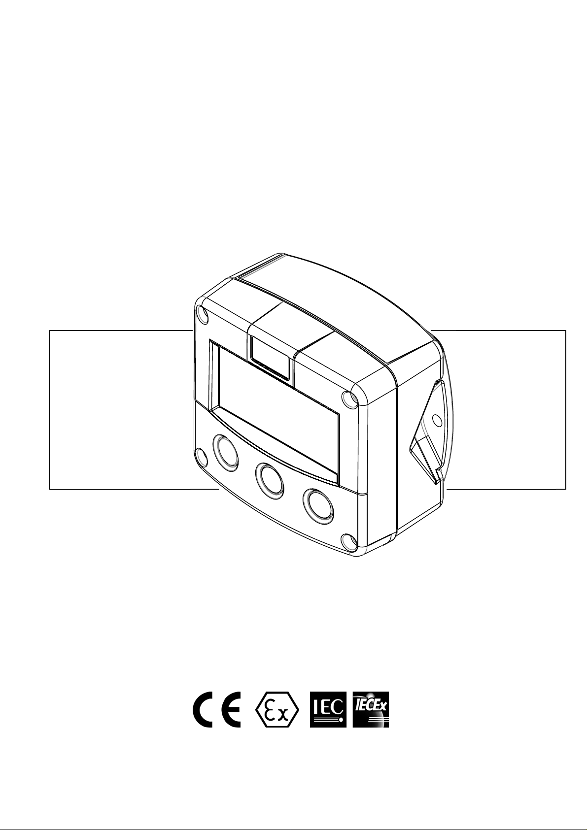
F151-A
DUAL PRESSURE INDICATOR
Signal input sensors: (0)4-20mA
Options: Intrinsically Safe, Modbus communication
Page 2

Page 2
SAFETY INSTRUCTIONS
Any responsibility is lapsed if the instructions and procedures as described in this
manual are not followed.
LIFE SUPPORT APPLICATIONS: The F151-A is not designed for use in life support
appliances, devices, or systems where malfunction of the product can reasonably be
expected to result in a personal injury. Customers using or selling these products for use
in such applications do so at their own risk and agree to fully indemnify the manufacturer
and supplier for any damages resulting from such improper use or sale.
Electro static discharge does inflict irreparable damage to electronics! Before installing
or opening the unit, the installer has to discharge himself by touching a well-grounded
object.
This unit must be installed in accordance with the EMC guidelines (Electro Magnetic
Compatibility).
Do connect a proper grounding to the aluminum casing as indicated if the F151-A has
been supplied with the 115-230V AC power-supply type PM. The green / yellow wire
between the back-casing and removable terminal-block may never be removed.
Intrinsically Safe applications: follow the instructions as mentioned in Chapter 5 and
consult “Fluidwell F1..-..-XI - Documentation for Intrinsic Safety”.
DISPOSAL
At the end of its life this product should be disposed of according to local regulations regarding
waste electronic equipment. If a battery is present in this product it should be disposed of
separately. The separate collection and recycling of your waste equipment will help to conserve
natural resources and ensure that it is recycled in a manner that protects the environment.
SAFETY RULES AND PRECAUTIONARY MEASURES
The manufacturer accepts no responsibility whatsoev er if the following safety rules and
precautions instructions and the procedures as described in this manual are not followed.
Modifications of the F151-A implemented without preceding written consent from the
manufacturer, will result in the immediate termination of product liability and warranty period.
Installation, use, maintenance and servicing of this equipment must be carried out by authorized
technicians.
Check the mains voltage and information on the manufacturer's plate before installing the unit.
Check all connections, settings and technical specifications of the various peripheral d evices
with the F151-A supplied.
Open the casing only if all leads are free of potential.
Never touch the electronic components (ESD sensitivity).
Never expose the system to heavier conditions than allowed according to the casing
classification (see manufacture's plate and chapter 4.2.).
If the operator detects errors or dangers, or disagrees with the safety precautions taken, then
inform the owner or principal responsible.
The local labor and safety laws and regulations must be adhered to.
HF151AEN_v0501_04
Page 3
Page 3
ABOUT THE OPERATION MANUAL
This operation manual is divided into two main sections:
The daily use of the unit is described in chapter 2 "Operation". These instructions are meant for
users.
The following chapters and appendices are exclusively meant for electricians/technicians. These
provide a detailed description of all software settings and hardware installation guidance.
This operation manual describes the standard unit as well as most of the options available. For
additional information, please contact your supplier.
A hazardous situation may occur if the F151-A is not used for the purpose it was designed for
or is used incorrectly. Please carefully note the information in this operating manual
indicated by the pictograms:
A "warning" indicates actions or procedures which, if not performed correctly, may lead to
personal injury, a safety hazard or damage of the F151-A or connected instruments.
A "caution" indicates actions or procedures which, if not performed correctly, may lead to
personal injury or incorrect functioning of the F151-A or connected instrument s.
A "note" indicates actions or procedures which, if not performed correctly, may indirectly
affect operation or may lead to an instrument response which is not planned.
Hardware version : 02.01.xx
Software version : 02.01.xx
Manual : HF151AEN_v0501_04
© Copyright 2011 : Fluidwell bv - The Netherlands.
Information in this manual is subject to change without prior notice. The
manufacturer is not responsible for mistakes in this material or for incidental
damage caused as a direct or indirect result of the delivery, performance or
use of this material.
© All rights reserved. No parts of this publication may be reproduced or used
in any form or by any means without written permission of your supplier.
HF151AEN_v0501_04
Page 4

Page 4
CONTENTS MANUAL
Safety instructions ........................................................................................................................................... 2
Safety instructions ........................................................................................................................................... 2
Disposal .................................................................................................................................................... 2
Safety rules and precautionary measures ....................................................................................................... 2
About the operation manual ............................................................................................................................ 3
Contents manual .............................................................................................................................................. 4
1. Introduction ................................................................................................................................. 5
1.1. System description of the F151-A .......................................................................................... 5
2. Operational .................................................................................................................................. 7
2.1. General .................................................................................................................................. 7
2.2. Control panel .......................................................................................................................... 7
2.3. Operator information and functions ....................................................................................... 8
3. Configuration ............................................................................................................................... 9
3.1. Introduction ............................................................................................................................ 9
3.2. Programming SETUP-level .................................................................................................... 9
3.2.1. General .................................................................................................................................. 9
3.2.2. Overview functions SETUP level ......................................................................................... 12
3.2.3. Explanation SETUP-functions .............................................................................................. 13
1 - PRESSURE - A ......................................................................................................... 13
2 - PRESSURE - B ......................................................................................................... 14
3 - Display ....................................................................................................................... 14
4 - Power management .................................................................................................. 15
5 - Sensor - A .................................................................................................................. 15
6 - Sensor - B .................................................................................................................. 17
7 - Communication (optional) .......................................................................................... 19
8 - Others ........................................................................................................................ 19
4. Installation ................................................................................................................................. 20
4.1. General directions ................................................................................................................ 20
4.2. Installation / surrounding conditions .................................................................................... 20
4.3. Dimensions- Enclosure ........................................................................................................ 21
4.4. Installing the hardware ......................................................................................................... 23
4.4.1. Introduction .......................................................................................................................... 23
4.4.2. Voltage selection sensor supply .......................................................................................... 24
4.4.3. Terminal connectors ............................................................................................................ 25
5. Intrinsically safe applications..................................................................................................... 27
5.1. General information and instructions ................................................................................... 27
5.2. Terminal connectors Intrinsically Safe applications ............................................................. 28
5.3. Configuration examples Intrinsically Safe applications ........................................................ 30
5.4 Battery replacement instructions .......................................................................................... 32
6. Maintenance .............................................................................................................................. 33
6.1. General directions ................................................................................................................ 33
Appendix A: Technical specification .............................................................................................................. 34
Appendix B: Problem solving ......................................................................................................................... 37
Appendix C: Communication variables .......................................................................................................... 38
HF151AEN_v0501_04
Page 5
Page 5
1. INTRODUCTION
1.1. SYSTEM DESCRIPTION OF THE F151-A
Functions and features
The pressure indicator model F151-A is a microprocessor driven instrument designed to display the
pressure measured by two separate sensors.
This product has been designed with a focus on:
ultra-low power consumption to allow long-life battery powered applications (option PB),
intrinsic safety for use in hazardous applications (option XI),
several mounting possibilities with ABS or aluminum enclosures for harsh industrial
surroundings,
Sensor input
This manual describes the unit with two analog (0)4-20mA inputs for the sensor "-A version". Other
versions are available to process 0-10V sensor signals.
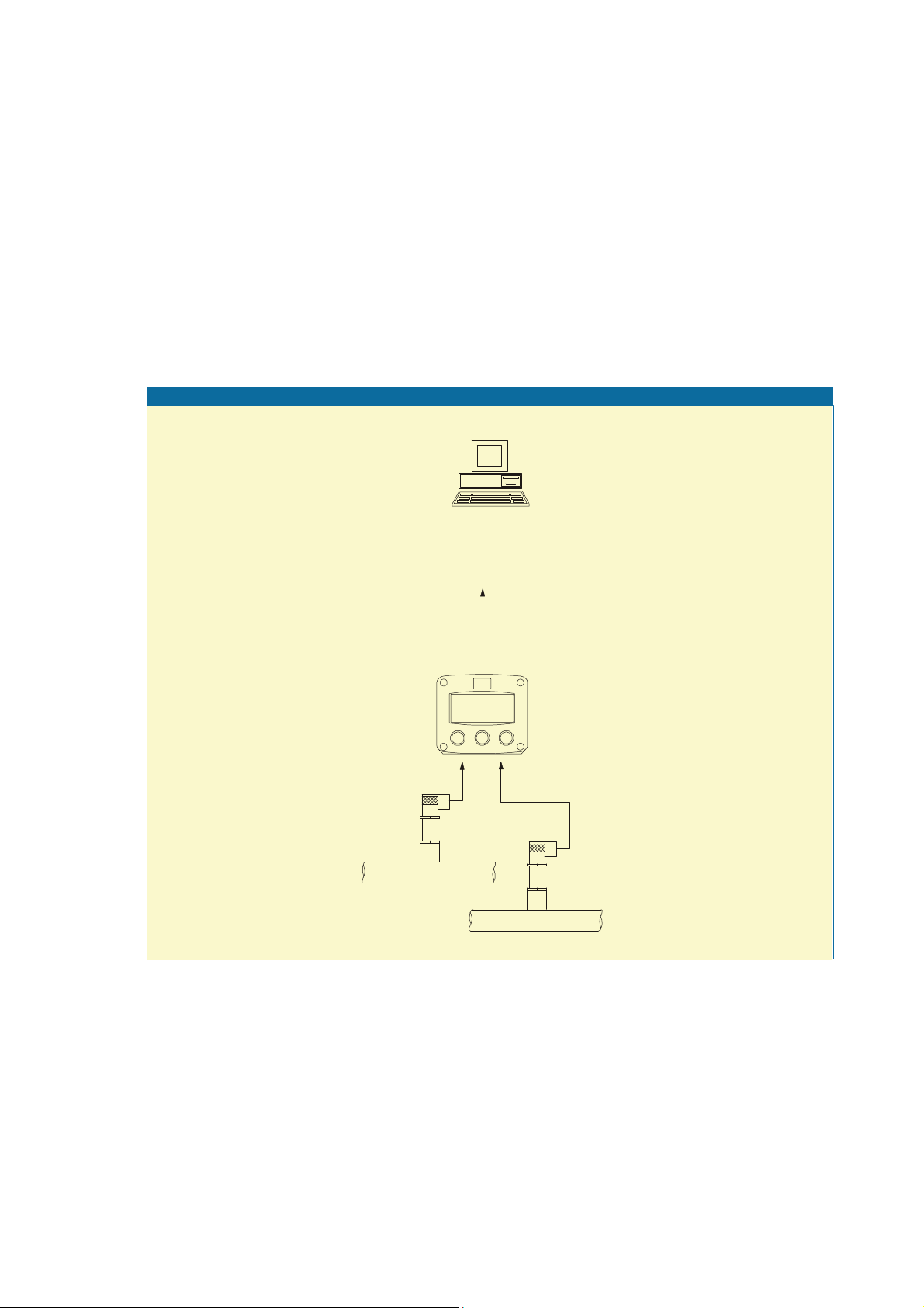
Overview typical application F151
RS232/RS485
Modbus
(option)
A: (0)4-20mA
U: 0-10V DC
Fig. 1: Typical application for the F151-A.
Configuration of the unit
The F151-A was designed to be implemented in many types of applications. For that reason, a
SETUP-level is available to configure your F151-A according to your specific requirements.
SETUP includes several important features, such as Span, measurement units, signal selection etc.
All setting as are stored in EEPROM memory and will not get lost in case of power break-down or
empty battery.
To extend the battery-life time (option), please make use of the power-management functions as
described in chapter 3.2.3.
HF151AEN_v0501_04
Page 6

Page 6
Display information
The unit has a large transflective LCD with all kinds of symbols and digits to display measuring units,
status information, trend-indication and key-word messages.
The measured pressure of each line can be displayed one by one or simultaneously.
Options
Following options are available: full Modbus communication RS232/485 (also battery powered),
intrinsic safety, power- and sensor-supply options, panel-mount, wall-mount and weather-proof
enclosures, flame proof enclosure.
HF151AEN_v0501_04
Page 7
Page 7
2. OPERATIONAL
2.1. GENERAL
The F151-A may only be operated by personnel who are authorized and trained by the
operator of the facility. All instructions in this manual are to be observed.
Take careful notice of the " Safety rules, instructions and precautionary measures " in
the front of this manual.
This chapter describes the daily use of the F151-A. This instruction is meant for users / operators.
2.2. CONTROL PANEL
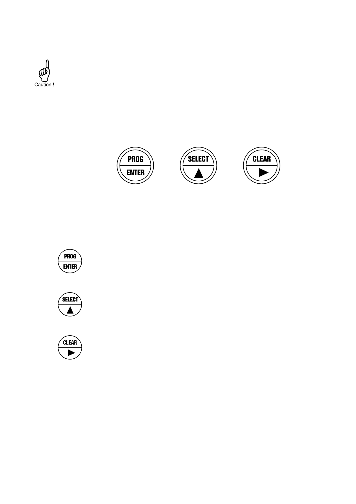
The following keys are available:
Fig. 2: Control Panel.
Functions of the keys
This key is used to program and save new values or settings.
It is also used to get access to SETUP-level; please read chapter 3.
This key is used to SELECT manually one of the actual pressure value’s.
The arrow-key is used to configure the unit; please read chapter 3.
T his key is used to select manually one of the actual pressure value’s.
The arrow-key is used configure the unit; please read chapter 3.
HF151AEN_v0501_04
Page 8
Page 8
2.3. OPERATOR INFORMATION AND FUNCTIONS
In general, the pressure indicator will always act at Operator level. The information displayed
depends on the SETUP-settings. Although the refresh-rate of the display might be slow (due to
power-management functions), the sensor signals will be processed at all times. After pressing a
key, the display will be updated very fast during 30 seconds after which it will slow-down again.
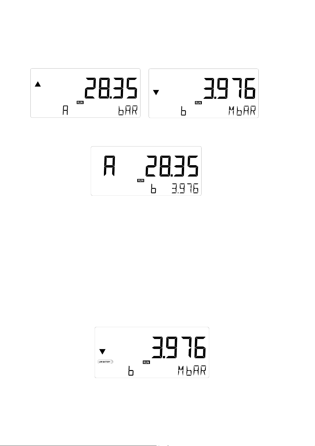
Fig. 3: Example display when the information is selected manually.
Fig. 4: Example display information when sensor A and B are displayed simultaneou sly.
For the Operator, the following functions are available:
Display pressure
The actual pressure is displayed with the 17mm digits at the upper line. When "-------" is
shown, the pressure is too high to be displayed. The arrows indicate the increase /
decrease of the pressure.
Depending on the settings, both pressures can be displayed simultaneously where the input
number is displayed as "A" or "b". When they are not displayed at the same time, then the
information can be selected manually or it will be displayed automatically with an interval time
of 6 seconds.
Low-battery alarm
When the battery voltage drops, it must be replaced. At first "low-battery" will flash, but as
soon as it is displayed continuously, the battery MUST be replaced shortly after!
Only official batteries may be used, or else the guarantee will be terminated. The remaining
lifetime after the first moment of indication is generally several days up to some weeks.
Fig. 5: Example of low-battery alarm.
Alarm 01-03
When "alarm" is displayed, please consult Appendix B: problem solving.
HF151AEN_v0501_04
Page 9
Page 9
3. CONFIGURATION
3.1. INTRODUCTION
This and the following chapters are exclusively meant for electricians and non-operators. In these,
an extensive description of all software settings and hardware connections are provided.
Mounting, electrical installation, start-up and maintenance of the instrument may only
be carried out by trained personnel authorized by the operator of the facility. Personnel
must read and understand this Operating Manual before carrying out its instructions.
The F151-A may only be operated by personnel who are authorized and trained by the
operator of the facility. All instructions in this manual are to be observed.
Ensure that the measuring system is correctly wired up according to the wiring
diagrams. The housing may only be opened by trained personnel.
Take careful notice of the " Safety rules, instructions and precautionary measures " in
the front of this manual.
3.2. PROGRAMMING SETUP-LEVEL
3.2.1. GENERAL
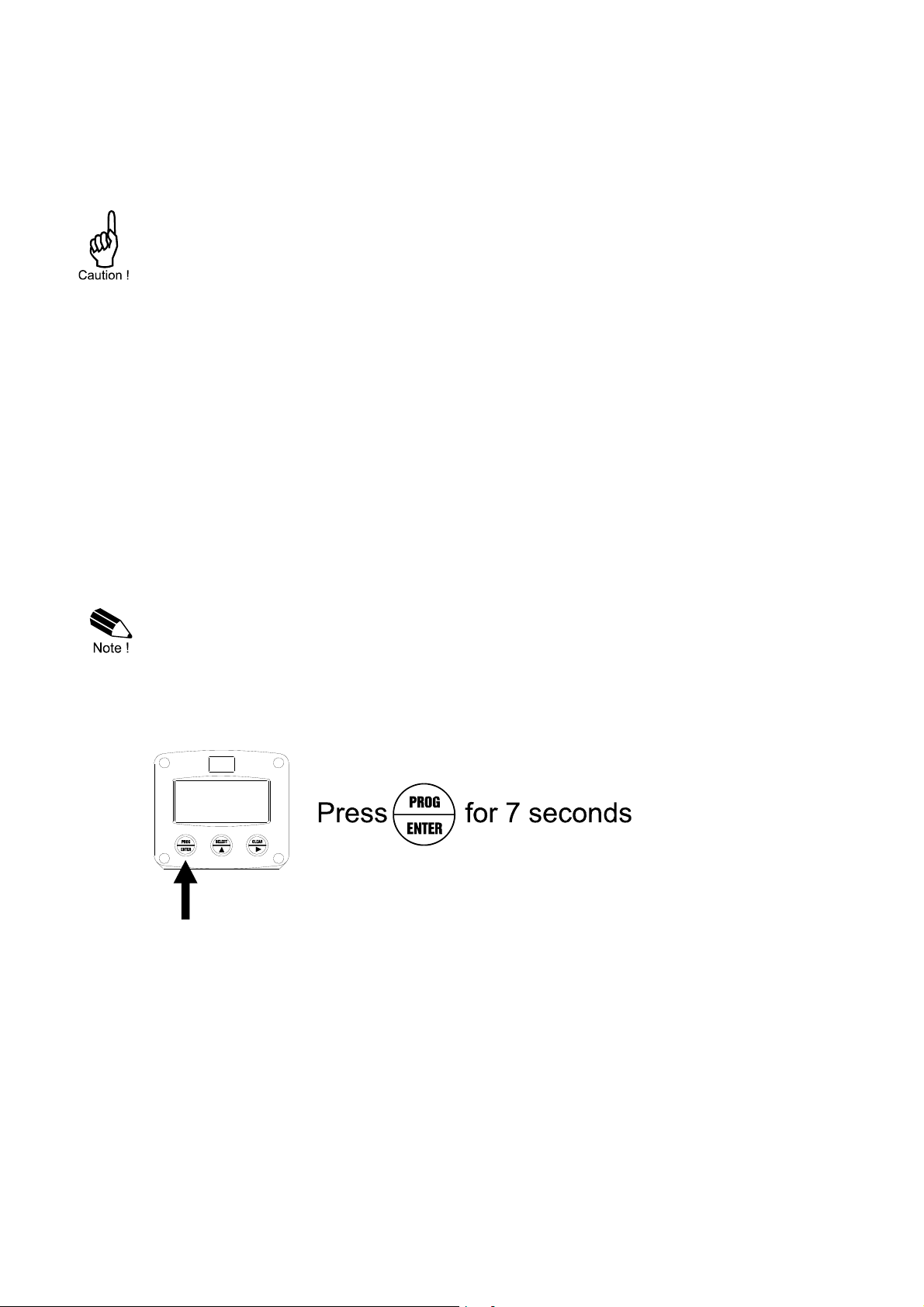
Configuration of the F151-A is done at SETUP-level. SETUP-level is reached by pressing the
PROG/ENTER key for 7 seconds; at which time, both arrows will be displayed. In order to return
to the operator level, PROG will have to be pressed for three seconds. Alternatively, if no keys are
pressed for 2 minutes, the unit will exit SETUP automatically.
SETUP can be reached at all times while the F151-A remains fully operational.
Note: A password may be required to enter SETUP. Without this password access to SETUP is
denied.
To enter SETUP-level:
HF151AEN_v0501_04
Page 10
Page 10
Matrix structure SETUP-level:
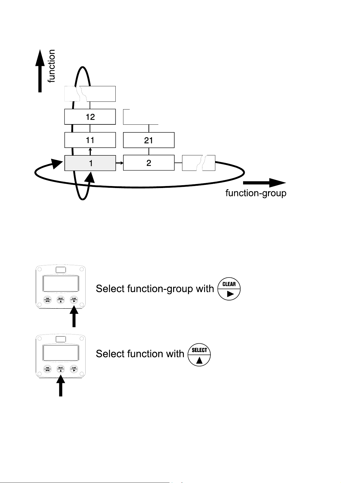
SCROLLING THROUGH SETUP-LEVEL
Selection function-group and function:
SETUP is divided into several function groups and functions.
Each function has a unique number, which is displayed below the word "SETUP" at the bottom of
the display. The number is a combination of two figures. The first figure indicates the function-group
and the second figure the function. Additionally, each function is expressed with a keyword.
After selecting a sub-function, the next main function is selected after scrolling through all "active"
sub-functions (e.g. 1, 11, 12, 13, 14, 1, 2, 3, 31 etc.).
HF151AEN_v0501_04
Page 11
Page 11
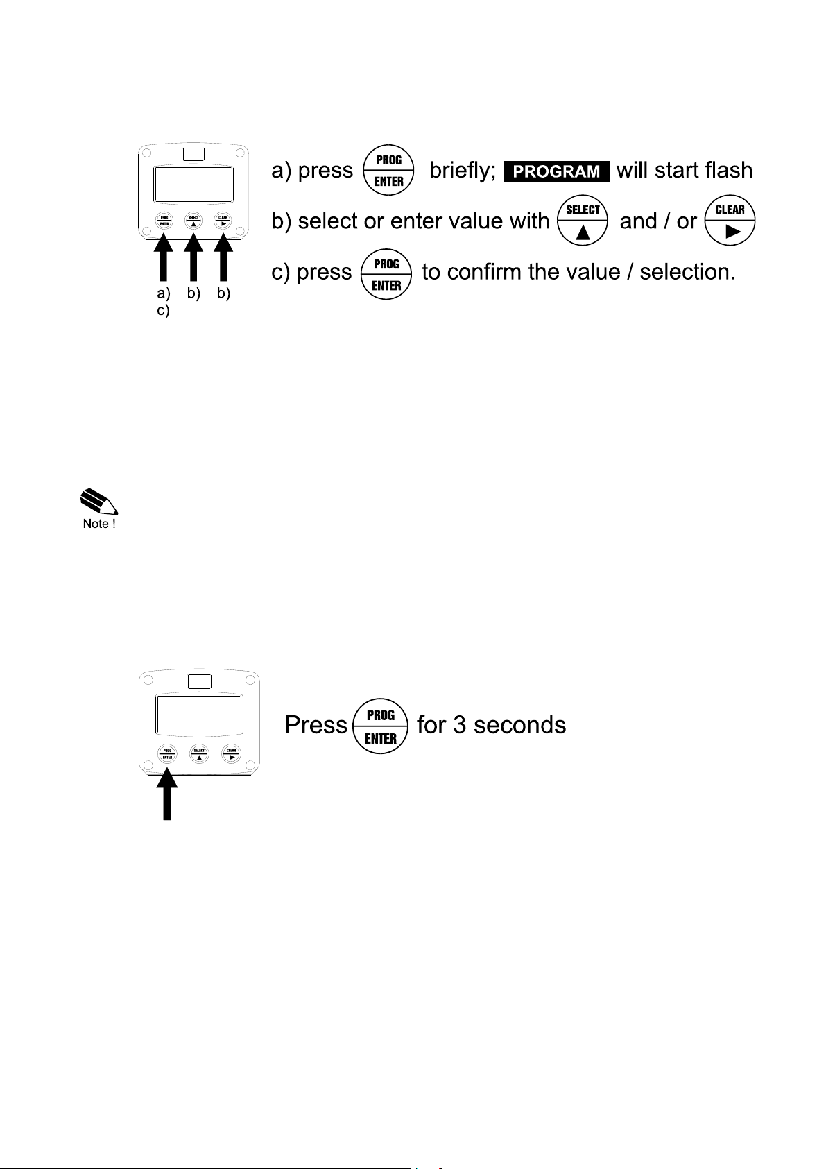
To change or a select a value or value:
To change a value, use to select the digits and to increase that value.
To select a setting, both and can be used.
When the new value is not valid, the increase sign or decrease-sign will be displayed while you
are programming.
When data is altered but ENTER is not pressed, then the alteration can still be cancelled by waiting
for 20 seconds or by pressing ENTER for three seconds: the PROG-procedure will be left
automatically and the former value reinstated.
Note: alterations will only be set after ENTER has been pressed!
To return to OPERATOR-level:
In order to return to the operator level, PROG will have to be pressed for three seconds. Also, when
no keys are pressed for 2 minutes, SETUP will be left automatically.
HF151AEN_v0501_04
Page 12
Page 12
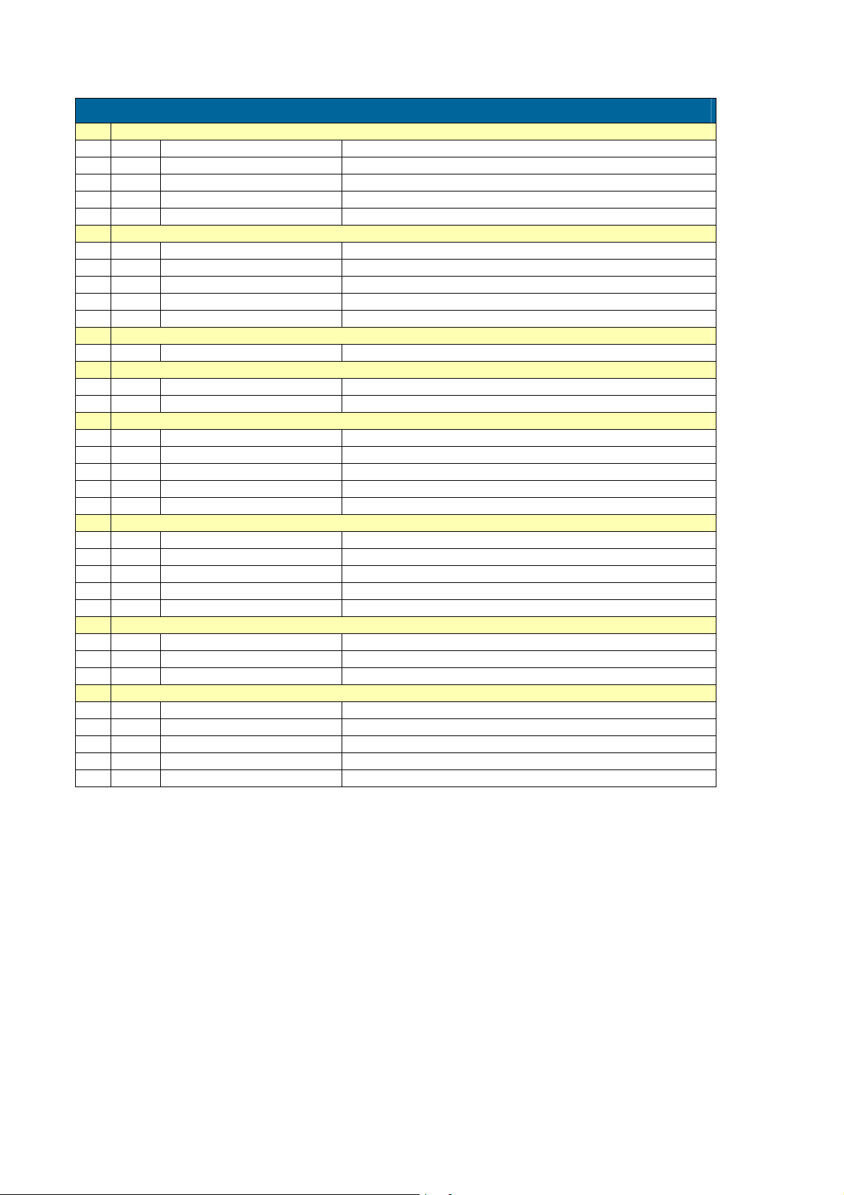
3.2.2. OVERVIEW FUNCTIONS SETUP LEVEL
SETUP FUNCTIONS AND VARIABLES
1 PRESSURE A
11 UNIT mbar - bar - psi - no unit
12 DECIMALS 0 - 1 - 2 - 3 (Ref: displayed value)
13 SPAN 0.000001 - 999,999 units
14 DECIMALS SPAN 0 - 6
15 OFFSET -999,999 - +999,999 units
2 PRESSURE B
21 UNIT mbar - bar - psi - no unit
22 DECIMALS 0 - 1 - 2 - 3 (Ref: displayed value)
23 SPAN 0.000001 - 999,999 units
24 DECIMALS SPAN 0 - 6
25 OFFSET -999,999 - +999,999 units
3 DISPLAY
31 DISPLAY toggle - A and B - hand
4 POWER MANAGEMENT
41 LCD UPDATE fast - 1 sec - 3 sec - 15 sec - 30 sec - off
42 BATTERY MODE operational - shelf
5 SENSOR A
51 FORMULA interpolation, square root
52 FILTER 00 - 99
53 CUT-O FF 0.0 - 99.9%
54 CALIBRATE LOW (0)4mA
55 CALIBRATE HIGH 20mA
6 SENSOR B
61 FORMULA interpolation, square root
62 FILTER 00 - 99
63 CUT-O FF 0.0 - 99.9%
64 CALIBRATE LOW (0)4mA
65 CALIBRATE HIGH 20mA
7 COMMUNICATION
71 SPEED / BAUDRATE 1200 - 2400 - 4800 - 9600
72 ADDRESS 1 - 255
73 MODE ASCII - RTU - off
8 OTHERS
81 TYPE / MODEL
82 SOFTWARE VERSION
83 SERIAL NO.
84 PASSWORD 0000 - 9999
85 TAGNUMBER 0000000 - 9999999
HF151AEN_v0501_04
Page 13
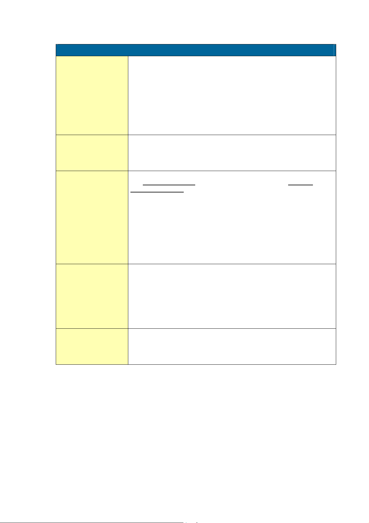
3.2.3. EXPLANATION SETUP-FUNCTIONS
1 - PRESSURE - A
MEASUREMENT UNIT
11
DECIMALS
12
SPAN
13
DECIMALS SPAN
14
OFF SET
15
SETUP - 11 determines the measurement unit for pressure measured
with sensor A (completely independent of sensor B).
The following units can be selected:
mbar - bar - psi - no unit
Alteration of the measurement unit will have consequences for operator
and SETUP-level values.
Please note that the Span has to be adapted as well; the calculation is not
done automatically.
This setting determines for pressure the number of digits following the
decimal point. The following can be selected:
00000 - 1111.1 - 2222.22 - 3333.333
With the span, the sensor signal is converted to a pressure.
The span for pressure is determined on the basis of the selected
measurement unit at 20mA.
Enter the span in whole numbers (decimals are set with SETUP 14).
The more accurate the span, the more accurate the functioning of the
system will be.
Example 1 Calculating the span for level
Let us assume that the sensor generates 20mA at a
pressure of 18.95 Bar and the selected unit is "mbar". The
span is 18,950 mbar, Enter for SETUP - 13: "18950" and
for SETUP - 14 - decimals span "0".
This setting determines the number of decimals for Span
(SETUP 13). The following can be selected:
0 - 1 - 2 - 3 - 4 - 5 - 6
Please note that this SETUP - influences the accuracy of the Span
indirectly.
This setting has NO influence on the displayed number of digits for
"pressure" (SETUP 12)!
Enter here the "not measured" pressure, in case a pressure transducer is
not placed in the bottom of a container but somewhere halfway for
example.
A negative offset can be entered by pressing the middle and right button
simultaneously.
Page 13
HF151AEN_v0501_04
Page 14
Page 14
MEASUREMENT UNIT
21
DECIMALS
22
SPAN
23
DECIMALS SPAN
24
OFF SET
25
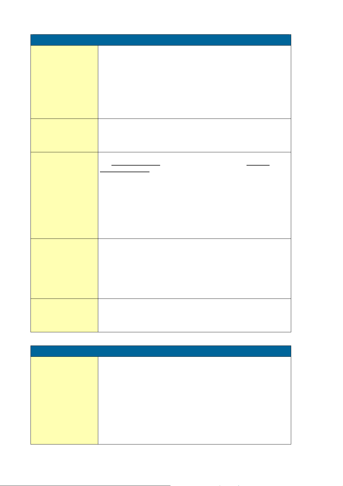
2 - PRESSURE - B
SETUP - 21 determines the measurement unit for pressure measured
with sensor B (completely independent of sensor A).
The following units can be selected:
mbar - bar - psi - no unit
Alteration of the measurement unit will have consequences for operator
and SETUP-level values.
Please note that the Span has to be adapted as well; the calculation is not
done automatically.
This setting determines for pressure the number of digits following the
decimal point. The following can be selected:
00000 - 1111.1 - 2222.22 - 3333.333
With the span, the sensor signal is converted to a pressure.
The span for pressure is determined on the basis of the selected
measurement unit at 20mA.
Enter the span in whole numbers (decimals are set with SETUP 24).
The more accurate the span, the more accurate the functioning of the
system will be.
Example 1 Calculating the span for level
Let us assume that the sensor generates 20mA at a
pressure of 18.95 Bar and the selected unit is "mbar". The
span is 18,950 mbar, Enter for SETUP - 23: "18950" and
for SETUP - 24 - decimals span "0".
This setting determines the number of decimals for Span
(SETUP 23). The following can be selected:
0 - 1 - 2 - 3 - 4 - 5 - 6
Please note that this SETUP - influences the accuracy of the Span
indirectly.
This setting has NO influence on the displayed number of digits for
"pressure" (SETUP 22)!
Enter here the "not measured" pressure, in case a pressure transducer is
not placed in the bottom of a container but somewhere halfway for
example.
Also, a negative offset can be entered: do press the middle and left button
simultaneously.
DISPLAY
31
3 - DISPLAY
The large 17mm digits and the 8mm digits can be set in several ways to
display the pressure and measuring units of both sensors.
Following can be selected:
• Toggle: the pressure, measuring unit and sensor number (A or B) of
each sensor will be displayed during 6 seconds followed with the
information of the other pressure sensor.
• Hand: as toggle but the selection must be made by pressing the
SELECT-button (manual selection by the operator).
• A and B: Pressure A is displayed with 17mm digits simultaneously
with pressure B with 8mm mm digits. No measuring units are
displayed; only the sensor number (A and B). All information of each
sensor can be selected by hand.
HF151AEN_v0501_04
Page 15
Page 15
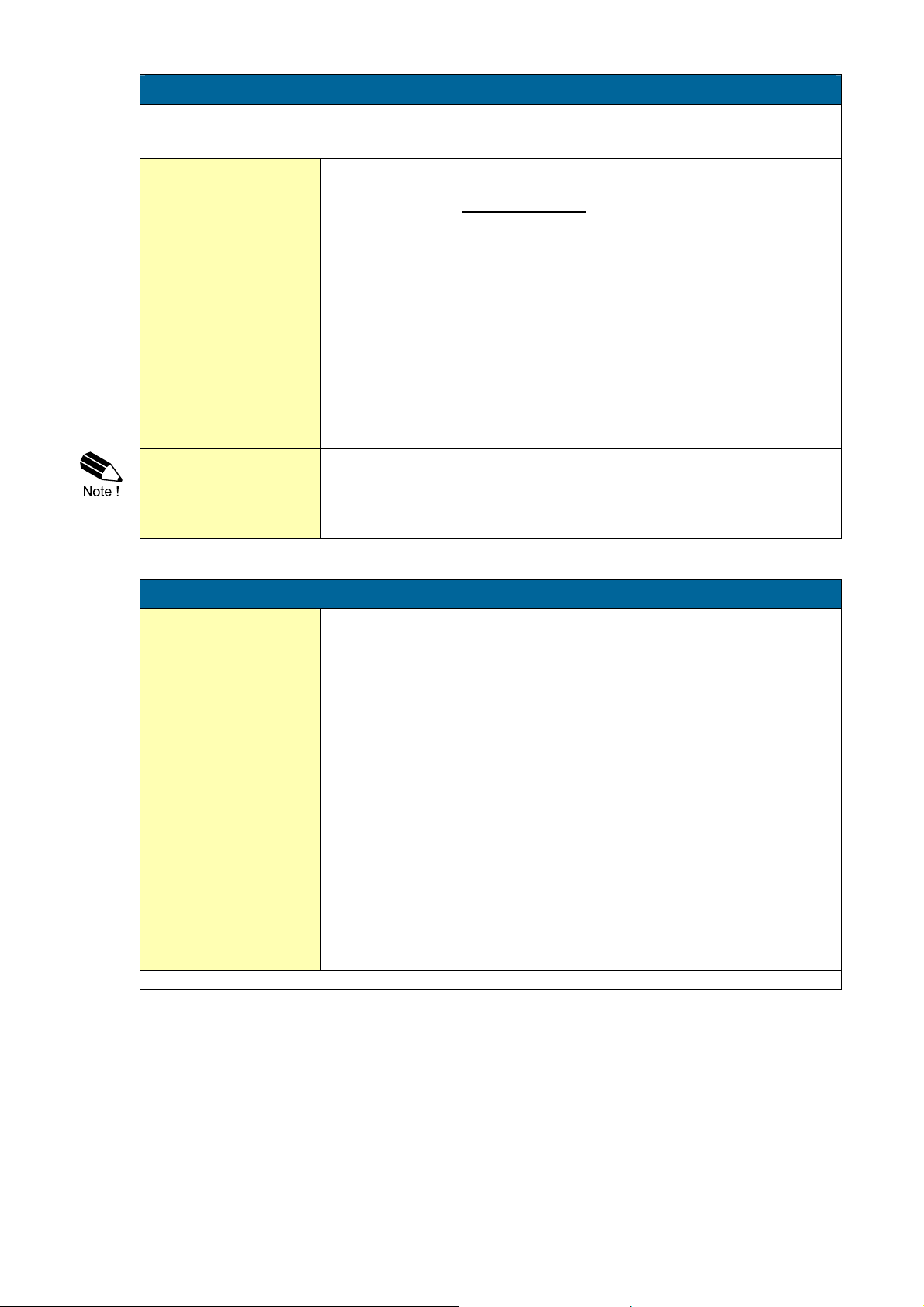
4 - POWER MANAGEMENT
When used with the internal battery option, the user may hold the concern of reliable measurement
over a long period of time. The F151-A has several smart power management functions to extend
the battery life time significantly. Two of these functions can be set:
LCD NEW
41
BATTERY-MODE
42
The calculation of the display-information influences the power
consumption significantly. When the application does not require a fast
display update, it is strongly advised to select a slow refresh-rate.
Please understand that NO information will be lost.
The following can be selected:
Fast - 1 sec - 3 sec - 15 sec - 30 sec - off.
Example 3: Battery life-time
battery life-time with FAST update: about 2 years.
battery life-time with 1 sec update: about 5 years.
Note: after a button has been pressed by the operator - the display
refresh-rate will always be FAST during 30 seconds. When "OFF" is
selected, the display will be switched-off after 30 seconds and will be
switched-on as soon as a button has been pressed.
The unit has two modes: operational or shelf.
After "shelf" has been selected, the unit can be stored for several years; it
will process the input signal, the display is switched-off but all settings are
stored. In this mode, power consumption is extremely low.
To wake-up the unit again; press the SELECT-key twice.
SIGNAL
51
Continued next page >>>
5 - SENSOR - A
The F151-A can process the (0)4-20mA signal of sensor A in two ways:
Interpolation: the signal is processed linear
Square root: for differential pressure
R = S x I
R = S √ I
where:
R = Rate: the calculated pressure
S = Span: the maximum pressure at 20mA. The span is
programmed with setting 13 for pressure
I = Input: the scaled analog value; in these formulas value 0 (zero)
for (0)4mA and value 1 (one)
for 20mA.
HF151AEN_v0501_04
Page 16
Page 16
5 - SENSOR - A (CONTINUED)
FILTER
52
FILTER VALUE RESPONSE TIME ON STEP CHANGE OF ANALOG VALUE.
50% INFLUENCE 75% INFLUENCE 90% INFLUENCE 99% INFLUENCE
01 filter disabled filter disabled filter disabled filter disabled
02 0.3 seconds 0.5 seconds 1.0 seconds 1.8 seco nds
03 0.5 seconds 1.0 seconds 1.5 seconds 3 seconds
05 1.0 seconds 1.8 seconds 2.8 seconds 5.3 seco nds
10 1.8 seconds 3.5 seconds 5.6 seconds 11 seconds
20 3.5 seconds 7.0 seconds 11 seconds 23 seconds
30 5.3 seconds 10 seconds 17 seconds 34 seconds
50 8.8 seconds 17 seconds 29 seconds 57 seconds
75 13 seconds 26 seconds 43 seconds 86 seconds
99 17 seconds 34 seconds 57 seconds 114 seconds
CUT-OFF
53
FUNCTION
(setup 51)
SPAN
(setup 13)
interpolation 450 PSI 25 PSI 25/450 x 100%=5.5% 16mA x 5.5% + 4mA = 4.88mA
square root 450 PSI 25 PSI (25/450)2 x 100%=0.3% 16mA x 0.3% + 4mA = 4.05mA
TUNE MIN / 4MA
54
Continued next page >>>
The analog output signal of a sensor does mirror the actual pressure.
This signal is measured several times a second by the F151-A. The value
measured is a "snap-shot" of the real pressure as it will be fluctuating.
With the help of this digital filter a stable and accurate reading can be
obtained while the filter level can be set to a desired value.
The filter principal is based on three input values: the filter level (01-99),
the last measured analog value and the last average value. The higher
the filter level, the longer the response time on a value change will be.
Below, several filter levels with there response times are indicated:
TIME IN SECONDS
To ignore e.g. vibration, a low-pressure cut-off can be set as percentage
over the full range of 16mA (or 20mA / 10V). When the analog value is
less then required with this setting, the signal will be ignored.
The cut-off value can be programmed is the range 0.0 - 99.9%.
Examples:
REQUIRED
CUT-OFF
With this setting it is possible to calibrate the input value for (0)4mA as the
signal from the sensor might not be exact 4.0 mA (or 0.0 mA) at minimum
pressure.
This function will measure the real output value at minimum pressure.
Warning: be very sure that the offered signal is correct
before the calibration is executed as this function has major
influences on the accuracy of the system!
After pressing PROG, three settings can be selected:
CALIBRATE: with this setting, the input will be calibrated with the
actual "(0)4mA" value. After pressing enter, CAL SET will be
displayed as soon as the calibration is completed. From that moment,
the analog value must be more than the calibrated value before the
signal will be processed.
DEFAULT: with this setting, the manufactures value is re-installed.
CAL SET: to select the last calibrated value.
CUT-OFF
(setup 53)
REQUIRED OUTPUT
HF151AEN_v0501_04
Page 17

TUNE MAX / 20MA
55
SIGNAL
61
Page 17
5 - SENSOR - A (CONTINUED)
With this setting it is possible to calibrate the input value for 20mA as the
signal from the sensor might not be exact 20.0 mA at maximum pressure.
This function will measure the real output value at maximum pressure.
Warning: be very sure that the offered signal is correct
before the calibration is executed as this function has major
influences on the accuracy of the system!
After pressing PROG, three settings can be selected:
CALIBRATE: with this setting, the input will be calibrated with the
actual "20mA" value. After pressing enter, CAL SET will be displayed
as soon as the calibration is completed. From that moment, the
analog value must be less than the calibrated value for a reliable
measurement.
DEFAULT: with this setting, the manufactures value is re-installed.
CAL SET: to select the last calibrated value.
6 - SENSOR - B
The F151-A can process the (0)4-20mA signal of sensor B in two ways:
Interpolation: the signal is processed linear
Square root: for differential pressure
R = S x I
Continued next page >>>
R = S √ I
where:
R = Rate: the calculated pressure
S = Span: the maximum pressure at 20mA. The span is
programmed with setting 13 for pressure
I = Input: the scaled analog value; in these formulas value 0 (zero)
for (0)4mA and value 1 (one)
for 20mA.
HF151AEN_v0501_04
Page 18
Page 18
6 - SENSOR - B (CONTINUED)
FILTER
62
FILTER VALUE RESPONSE TIME ON STEP CHANGE OF ANALOG VALUE.
50% INFLUENCE 75% INFLUENCE 90% INFLUENCE 99% INFLUENCE
01 filter disabled filter disabled filter disabled filter disabled
02 0.3 seconds 0.5 seconds 1.0 seconds 1.8 seco nds
03 0.5 seconds 1.0 seconds 1.5 seconds 3 seconds
05 1.0 seconds 1.8 seconds 2.8 seconds 5.3 seco nds
10 1.8 seconds 3.5 seconds 5.6 seconds 11 seconds
20 3.5 seconds 7.0 seconds 11 seconds 23 seconds
30 5.3 seconds 10 seconds 17 seconds 34 seconds
50 8.8 seconds 17 seconds 29 seconds 57 seconds
75 13 seconds 26 seconds 43 seconds 86 seconds
99 17 seconds 34 seconds 57 seconds 114 seconds
CUT-OFF
63
FUNCTION
(setup 61)
SPAN
(setup 23)
interpolation 450 PSI 25 PSI 25/450 x 100%=5.5% 16mA x 5.5% + 4mA = 4.88mA
square root 450 PSI 25 PSI (25/450)2 x 100%=0.3% 16mA x 0.3% + 4mA = 4.05mA
TUNE MIN / 4MA
64
Continued next page >>>
The analog output signal of a sensor does mirror the actual pressure.
This signal is measured several times a second by the F151-A. The value
measured is a "snap-shot" of the real pressure as it will be fluctuating.
With the help of this digital filter a stable and accurate reading can be
obtained while the filter level can be set to a desired value.
The filter principal is based on three input values: the filter level (01-99),
the last measured analog value and the last average value. The higher
the filter level, the longer the response time on a value change will be.
Below, several filter levels with there response times are indicated:
TIME IN SECONDS
To ignore e.g. vibration, a low-pressure cut-off can be set as percentage
over the full range of 16mA (or 20mA / 10V). When the analog value is
less then required with this setting, the signal will be ignored.
The cut-off value can be programmed is the range 0.0 - 99.9%.
Examples:
REQUIRED
CUT-OFF
With this setting it is possible to calibrate the input value for (0)4mA as the
signal from the sensor might not be exact 4.0 mA (or 0.0 mA) at minimum
pressure.
This function will measure the real output value at minimum pressure.
Warning: be very sure that the offered signal is correct
before the calibration is executed as this function has major
influences on the accuracy of the system!
After pressing PROG, three settings can be selected:
CALIBRATE: with this setting, the input will be calibrated with the
actual "(0)4mA" value. After pressing enter, CAL SET will be
displayed as soon as the calibration is completed. From that moment,
the analog value must be more than the calibrated value before the
signal will be processed.
DEFAULT: with this setting, the manufactures value is re-installed.
CAL SET: to select the last calibrated value.
CUT-OFF
(setup 63)
REQUIRED OUTPUT
HF151AEN_v0501_04
Page 19
Page 19
6 - SENSOR - B (CONTINUED)
TUNE MAX / 20MA
65
With this setting it is possible to calibrate the input value for 20mA as the
signal from the sensor might not be exact 20.0 mA at maximum pressure.
This function will measure the real output value at maximum pressure.
Warning: be very sure that the offered signal is correct
before the calibration is executed as this function has major
influences on the accuracy of the system!
After pressing PROG, three settings can be selected:
CALIBRATE: with this setting, the input will be calibrated with the
actual "20mA" value. After pressing enter, CAL SET will be displayed
as soon as the calibration is completed. From that moment, the
analog value must be less than the calibrated value for a reliable
measurement.
DEFAULT: with this setting, the manufactures value is re-installed.
CAL SET: to select the last calibrated value.
7 - COMMUNICATION (OPTIONAL)
Functions as described below deal with hardware that are not pa rt of the standard delivery.
Programming of these functions does not have any effect if this hardware has not been installed.
Consult Appendix C and the Modbus communication protocol description for a detailed explanation.
BAUDRATE
71
BUS ADDRESS
72
MODE
73
For external control, following communication speeds can be selected:
1200 - 2400 - 4800 - 9600 baud
For communication purposes, a unique identity can be attributed to every
F151-A. This address can vary from 1-255.
The communication is executed according Modbus protocol ASCII or RTU
mode. With OFF, the communication is disabled.
TYPE OF MODEL
81
VERSION SOFTWARE
82
SERIAL NUMBER
83
PASSWORD
84
TAGNUMBER
85
8 - OTHERS
For support and maintenance it is important to have information about the
characteristics of the F151-A.
Your supplier will ask for this information in the case of a serious
breakdown or to assess the suitability of your model for upgrade
considerations.
For support and maintenance it is important to have information about the
characteristics of the F151-A.
Your supplier will ask for this information in the case of a serious
breakdown or to assess the suitability of your model for upgrade
considerations.
For support and maintenance it is important to have information about the
characteristics of the F151-A.
Your supplier will ask for this information in the case of a serious
breakdown or to assess the suitability of your model for upgrade
considerations.
All SETUP-values can be password protected.
This protection is disabled with value 0000 (zero).
Up to and including 4 digits can be programmed, for example 1234.
For identification of the unit and communication purposes, a unique
tagnumber of maximum 7 digits can be entered.
HF151AEN_v0501_04
Page 20
Page 20
4. INSTALLATION
4.1. GENERAL DIRECTIONS
Mounting, electrical installation, start-up and maintenance of this instrument may only be carried
out by trained personnel authorized by the operator of the facility. Personnel must read and
understand this Operating Manual before carrying out its instructions.
The F151-A may only be operated by personnel who are authorized and trained by the operator
of the facility. All instructions in this manual are to be observed.
Ensure that the measuring system is correctly wired up according to the wiring diagrams.
Protection against accidental contact is no longer assured when the housing cover is removed
or the panel cabinet has been opened (danger from electrical shock). The housing may only be
opened by trained personnel.
Take careful notice of the " Safety rules, instructions and precautionary measures " at the front
of this manual.
4.2. INSTALLATION / SURROUNDING CONDITIONS
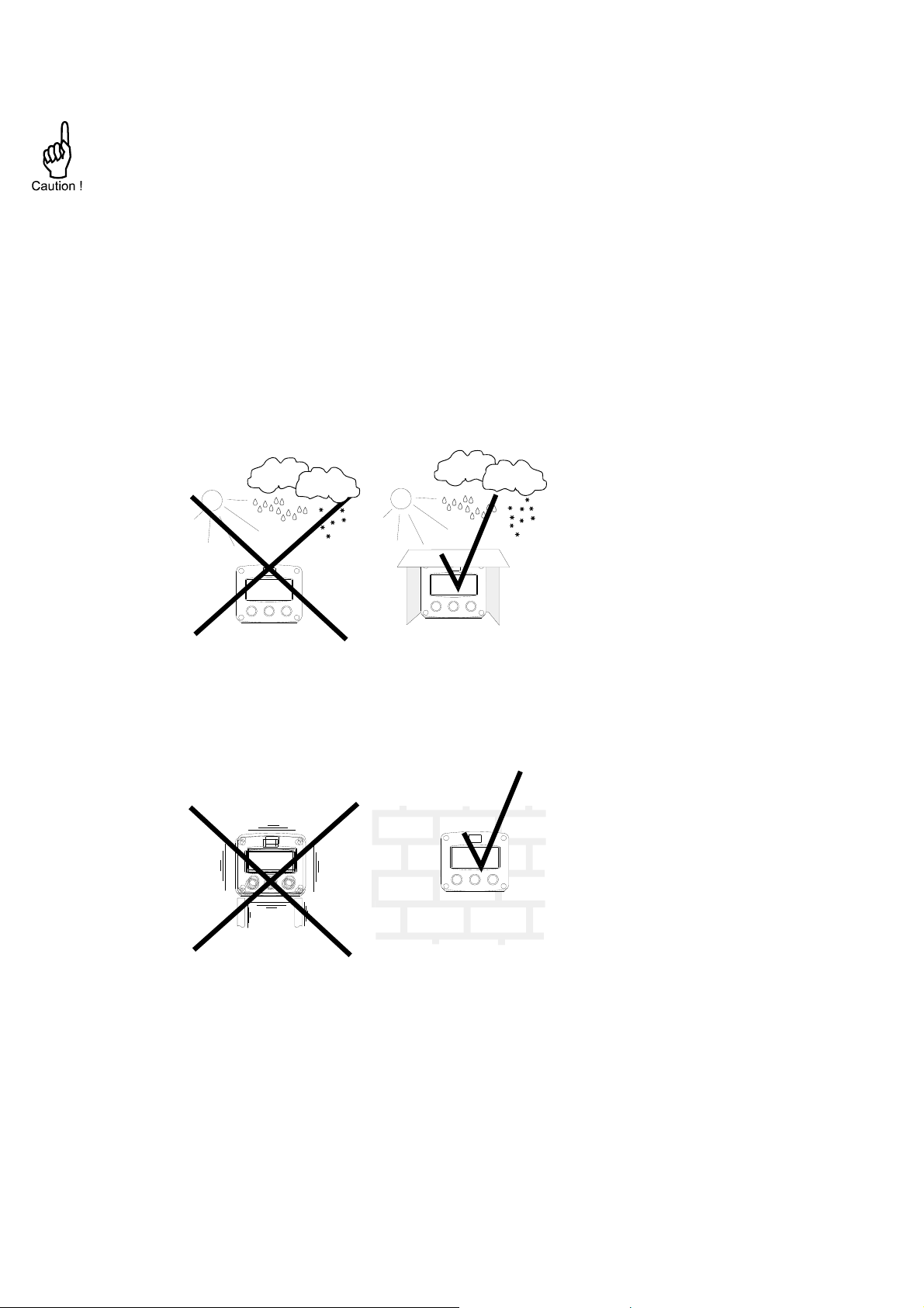
Take the relevant IP classification of the casing into account (see manufactures plate). Even an IP67
(NEMA 4X) casing should NEVER be exposed to strongly varying (weather) conditions.
When panel-mounted, the unit is IP65 (NEMA 4X)!
When used in very cold surroundings or varying climatic conditions, take the necessary precautions
against moisture by placing a dry sachet of silica gel, for example, inside the instrument case.
Mount the F151-A on a solid structure to avoid vibrations.
HF151AEN_v0501_04
Page 21
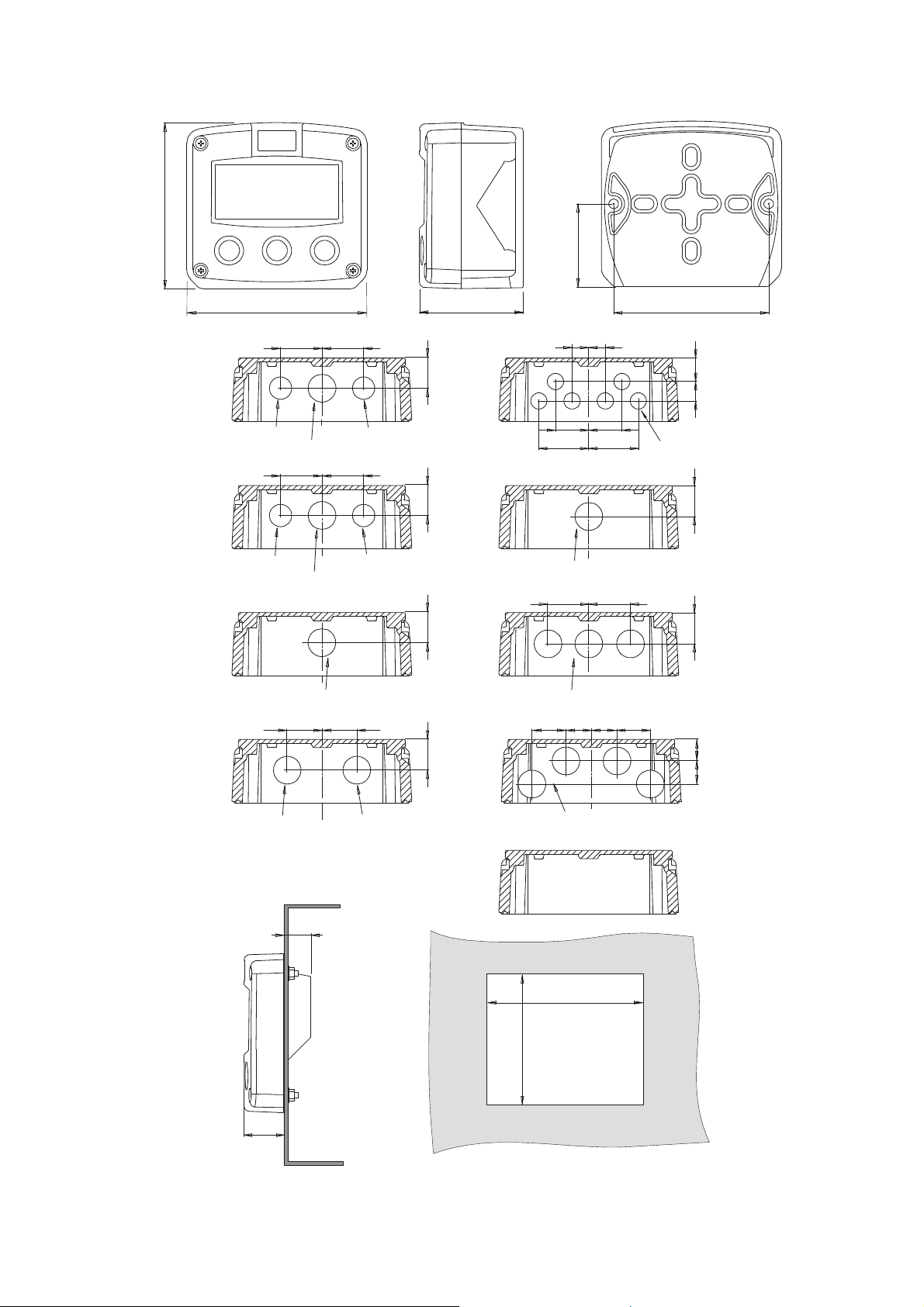
4.3. DIMENSIONS- ENCLOSURE
Aluminum enclosures:
120 mm (4.72")
130 mm (5.12")
30mm 30mm
75 mm (2.95")
60 mm (2.36")
112 mm (4.40")
12mm
12mm
Page 21
HA
HM
HN
HO
PG9
M20 x 1,5
30mm 30mm
M16 x 1,5 M16 x 1,5
M20 x 1,5
M20 x 1,5
25mm 25mm
M20 x 1,5 M20 x 1,5
PG9
22,5mm
22,50mm
22,5mm
22,5mm
24mm24mm
36mm
4x M20 x 1,5
36mm
1/2"NPT
0.12" 0.12"
3x 1/2"NPT
15 15
mm
2323
6 x M12
HP
14mm 17mm
0.9"
HT
0.9"
HU
15
16
HV
HB
31 mm
(1.22”)
HZ
29.1 mm (1.15”)
115 mm (4.53”)
98 mm (3.86”)
Fig. 6: Dimensions aluminum enclosures.
HF151AEN_v0501_04
Page 22
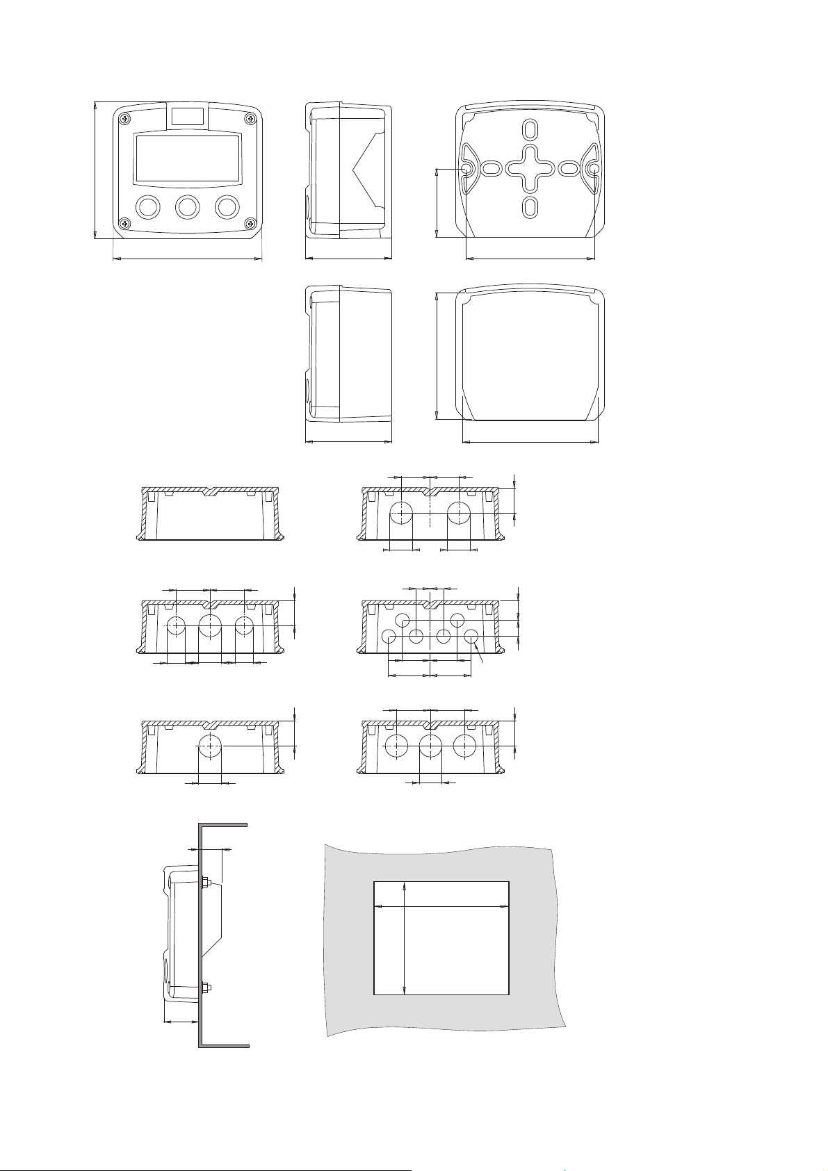
Page 22
GRP enclosures:
120 mm (4.72")
130 mm (5.12")
HK back box:
75 mm (2.95")
60 mm (2.36")
112 mm (4.40")
(flat bottom)
HD
HK
HE
D=16mm
HF
30mm 30mm
D=16mm
D=20mm
75 mm (2.95")
22,5mm
0.9"
25mm 25mm
D=20mm
12mm
36mm
0.12” 0.12”
104 mm (4.09”)
D=20mm
12mm
24mm24mm
36mm
118 mm (4.65”)
22,5mm
14mm 17mm
D=12mm
0.9”
HG
HH
HJ
HC
D=22mm (0.866")
29.1 mm (1.15”)
31 mm
(1.22”)
3x D=22mm (0.866”)
115 mm (4.53”)
98 mm (3.86”)
Fig. 7: Dimensions GRP enclosures.
HF151AEN_v0501_04
Page 23
Page 23
4.4. INSTALLING THE HARDWARE
4.4.1. INTRODUCTION
Electro static discharge does inflict irreparable damage to electronics! Before installing or
opening the unit, the installer has to discharge himself by touching a well-grounded object.
This unit must be installed in accordance with the EMC guidelines (Electro Magnetic
Compatibility).
Aluminum enclosures
When installed in an aluminum enclosure and a potentially explosive atmosphere requi ring
apparatus of equipment protection level Ga and Da, the unit must be installed such that, even in
the event of rare incidents, an ignition source due to impact or friction sparks between the
enclosure and iron/steel is excluded.
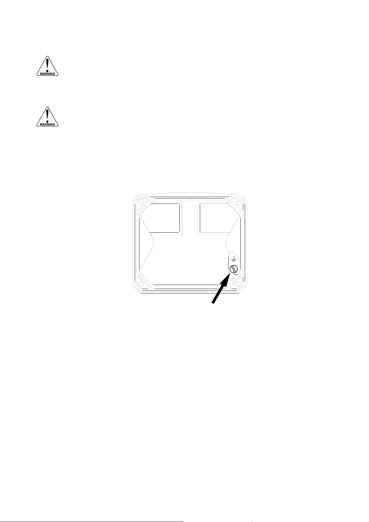
Do ground the aluminum enclosure properly as indicated, if the F151-A has been supplied with
the 115-230V AC power-supply type PM. The green / yellow wire between the back-casing and
removable terminal-block may never be removed.
Fig. 8: Grounding aluminum enclosure with type PM 115-230V AC.
FOR INSTALLATION, PAY EMPHATIC ATTENTION TO:
Separate cable glands with effective IP67 (NEMA4X) seals for all wires.
Unused cable entries: ensure that you fit IP67 (NEMA4X) plugs to maintain rating.
A reliable ground connection for both the sensor, and if applicable, for the metal casing.
An effective screened cable for the input signal, and grounding of its screen to terminal 9 (GND)
or at the sensor itself, whichever is appropriate to the application.
HF151AEN_v0501_04
Page 24
Page 24
4.4.2. VOLTAGE SELECTION SENSOR SUPPLY
For Intrinsically Safe applications: read chapter 5.
Battery powered and output loop-powered applications:
Terminal 11 provides a limited supply voltage of 3.2 V DC which is not sufficient to power a (0)420mA or 0-10V sensor.
Option PD-PM: Sensor supply: 3.2V - 8.2V - 12V or 24 V:
With this option, a real power supply for the sensor is available. The sensor can be powered with 8.2
- 12 or 24 V DC (max. 50mA@24V). The voltage is selected by the three switches inside the
enclosure.
Warning: be sure that all the leads to the terminals are disconnected from the unit when
the internal plastic protection cover has been removed !
HIGH VOLTAGE 400V !! NEVER connect the mains power supply to the unit when the
plastic protection cover has been removed !!!
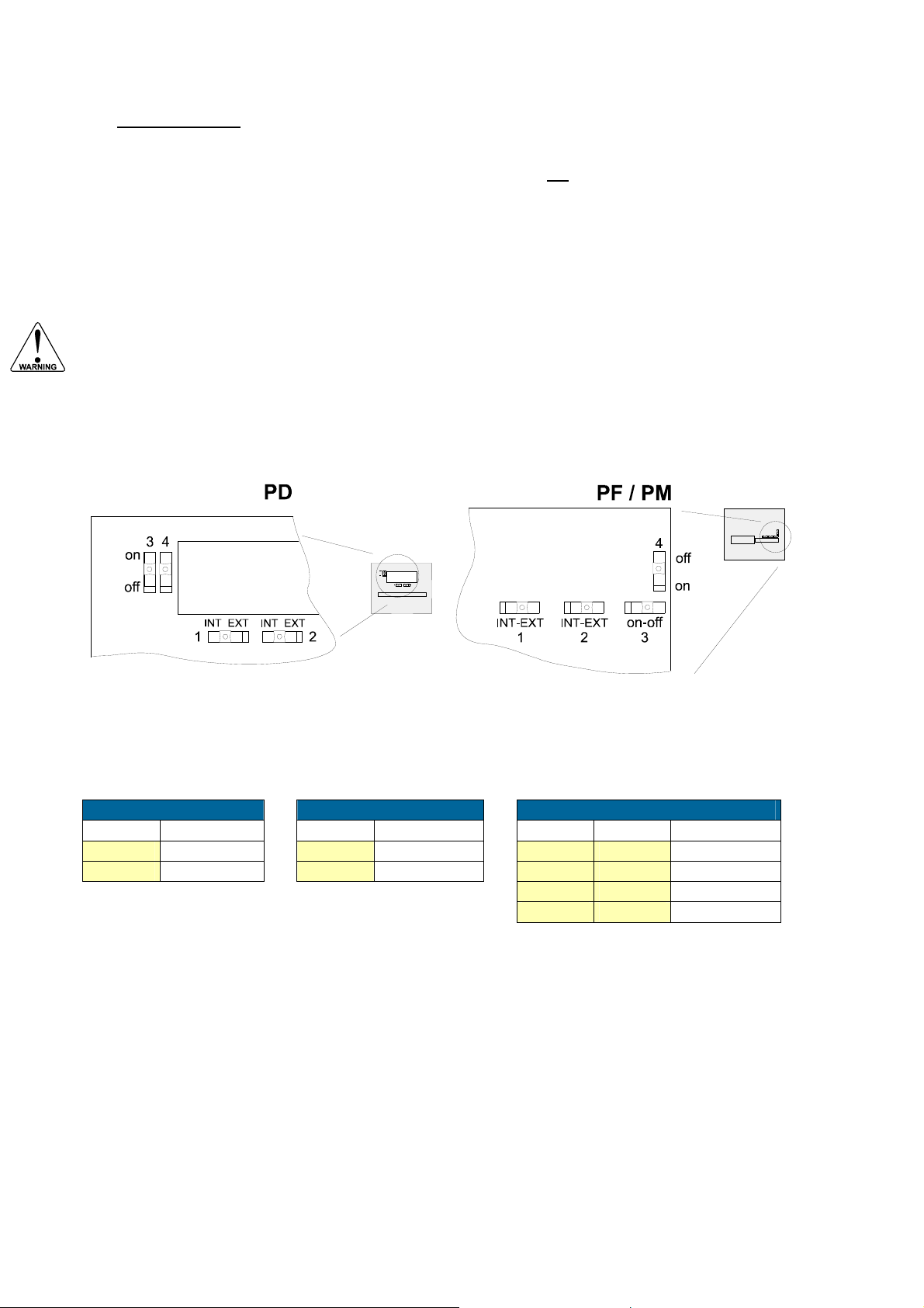
First, remove the terminal strip(s) after which the internal plastic cover can be removed. The
switches are located in the top left corner (option PD) or on the right hand (option PF / PM) as
indicated:
Fig. 9: switch position voltage selection (option PD, PF and PM).
Switch positions
SENSOR A SENSOR B VOLTAGE SELECTION
SWITCH 1 VOLTAGE SWITCH 2 VOLTAGE SWITCH 3 SWITCH 4 VOLTAGE
internal 3.2 V DC internal 3.2 V DC on on 8.2 V DC
external switch 3+4 external switch 3+4 off on 12 V DC
on off 12 V DC
off off 23 V DC
Function switch 1: voltage selection sensor A - terminal 11.
Function switch 2: voltage selection sensor B - terminal 14.
Function switch 3+4: the combination of these switches determine the voltage as indicated.
If switch 1 and 2 are both set to position OFF than the selected voltage with switch 3+4 is valid for
both sensors.
HF151AEN_v0501_04
Page 25
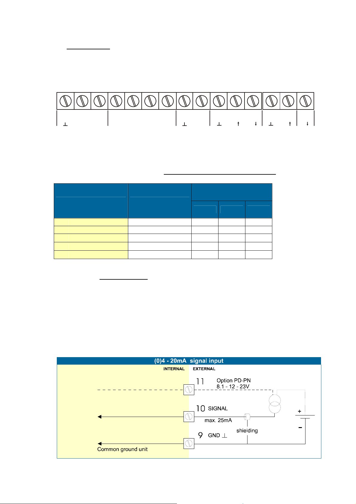
4.4.3. TERMINAL CONNECTORS
(0)
For Intrinsically Safe applications: read chapter 5.
The following terminal connectors are available:
OPTION:
POWER SUPPLY:
PD / PF / PM
(standard)
POWER
SUPPL Y
SENSOR A
(0)4-20mA
SUPPLY
DC
SENSOR B
4-20mA
Page 25
SUPPLY
DC
2 65
NL1
78GND 314
9101112 1413
+
+I+I
Fig. 10: Overview terminal connectors standard configuration F151-A and options.
REMARKS TERMINAL CONNECTORS:
Terminal GND- 01- 02; power supply - only available with option PD, PF or PM:
Terminal
OPTION SENSOR SUPPLY
GND 01 02
PD 8-24V AC 8,2-12-24V max 50mA
PD 8-30V DC 8,2-12-24V max 50mA L- L+
PF
24V AC ± 15%
PF
24V DC ± 15%
PM
115-230V AC ± 15%
Terminal 07-08 POWER SUPPLY (standard):
Connect an external power supply of 8-24 volts AC or 8-30VDC to these terminals or a 4-20mA loop.
For a DC supply: connect the "-" to terminal 7 and the "+" to terminal 8. When power is applied to
these terminals, the (optional) internal battery will be disabled / enabled automatically to extend the
battery life time. The sensor supply voltage available on terminal 11 and 14 is only 3.2V.
Terminal 09-11: Type A – sensor input A (general)
The F111-A requires a (0)4-20mA sensor signal which will be processed 4 times a second with a 14
bits accuracy. The input is not isolated.
For Intrinsically safe applications (without input loop power): please read chapter 5.
8,2-12-24V max 50mA
8,2-12-24V max 50mA L- L+
8,2-12-24V max 50mA EARTH AC AC
AC AC
AC AC
HF151AEN_v0501_04
Page 26
Page 26
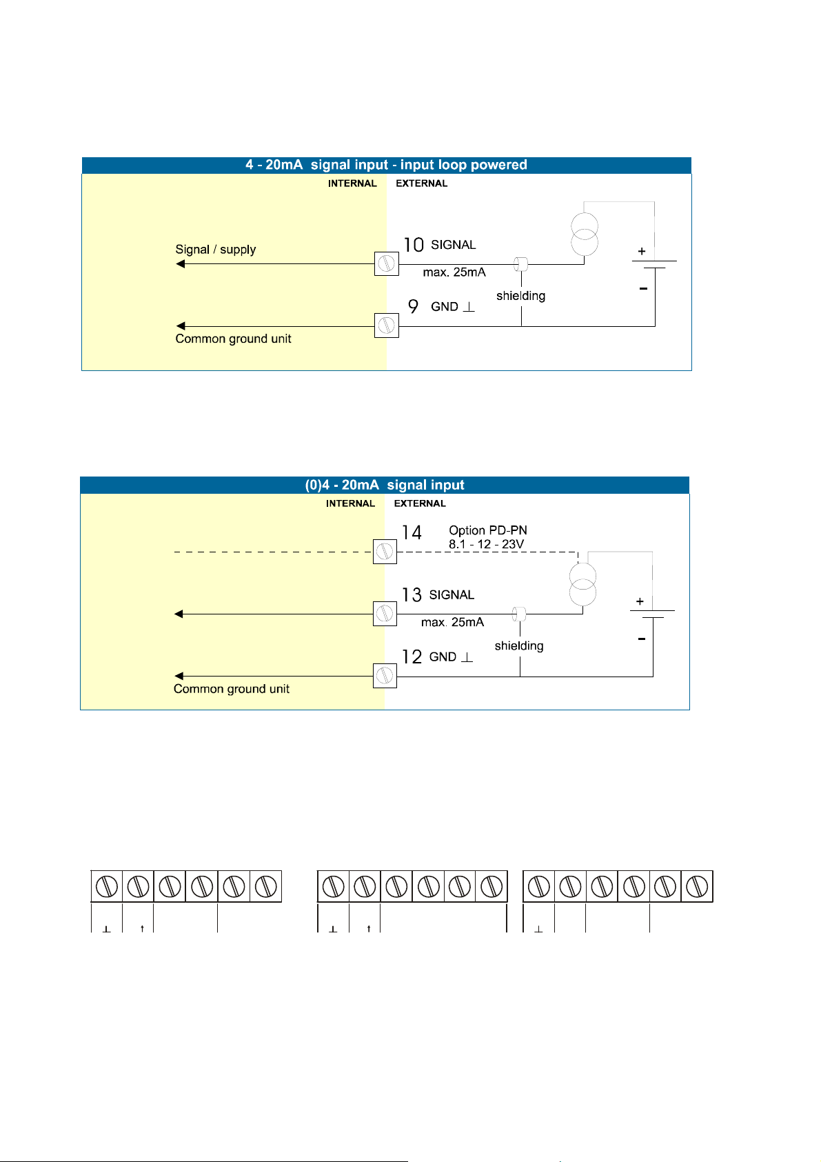
Terminal 09-10: Type A-PL – sensor input A / power supply:
The F111-A-PL requires a 4-20mA sensor signal which has a double function:
The signal will be processed 4 times a second with a 14 bits accuracy and the unit will be powered
from the sensor signal (input loop powered). The input is not isolated and not intrinsically safe.
Terminal 12-14; Sensor input B:
The F151-A requires a (0)4-20mA sensor signal which will be processed 4 times a second with a 14
bits accuracy. The input is not isolated.
For Intrinsically safe applications: please read chapter 5.
Option - communication/printer RS232/RS485:
see the manufacturer's plate.
Full serial communications and computer control in accordance with RS232 (length of cable
max. 15 meters) or RS485 (length of cable max. 1200 meters) is possible.
Read the Modbus communication protocol and Appendix C.
RS485 - 2-wire
26 27 29
28
A B+
30 31 30 31
26 27
RS485 - 4-wire
29
28
A B+
30 31
Y
Z
RS232
26 27 29
DTR
+12V
28
RXD TXD
Fig. 11: Overview terminal connectors communication option.
When using the RS232 communication option, terminal 27 is used for supplying the interface.
Please connect the DTR (or the RTS) signal of the interface to this terminal and set it active (+12V).
If no active signal is available it is possible to connect a separte supply between terminals 26
and 27 with a voltage between 8V and 24V.
HF151AEN_v0501_04
Page 27
Page 27
5. INTRINSICALLY SAFE APPLICATIONS
5.1. GENERAL INFORMATION AND INSTRUCTIONS
Cautions
Mounting, electrical installation, start-up and maintenance of this dev ice may only be carried out
by trained personnel authorized by the operator of the facility. Personnel must read and
understand this Operating Manual before carrying out its instructions.
This device may only be operated by personnel who are authorized and trained by the operator
of the facility. All instructions in this manual are to be observed.
Ensure that the measuring system is correctly wired up according t o the wiring diagrams.
Protection against accidental contact is no longer assured when the housing cover is removed
or the cabinet has been opened (danger of electric shock). The housing may only be opened by
trained personnel.
To maintain the degree of protection of at least IP65 in accordance with IEC 60529, certified
cable entries in accordance with IEC 61241-0 must be used and correctly installed. Unused
openings must be closed with suitable blanking elements.
When the enclosure of the Indicator is made of aluminum alloy, when used in a potentially
explosive atmosphere requiring apparatus of equipment protection level Ga and Da, the unit
must be installed such that, even in the event of rare incidents, an ignition source due to impact
or friction sparks between the enclosure and iron/steel is excluded.
Take careful notice of the " Safety rules, instructions a nd precautionary measures " in the front
of this manual.
Safety Instructions
When two or more active intrinsically safe circuits are connected to the indicator, in order to
prevent voltage and/or current addition, applicable to the external circuits, precautions must be
taken to separate the intrinsically safe circuits in accordance with IEC 60079-11.
For the combined connection of the different supply, input and output circuits, th e instructions in
this manual must be observed.
From the safety point of view the circuits shall be considered to be conne cted to earth.
For installation under ATEX directive: this intrinsically safe device must be installed in
accordance with the Atex directive 94/9/EC and the product certificate KEMA 03ATEX1074 X.
For installation under IECEx scheme: this intrinsically safe device must be installed in
accordance the product certificate IECEx DEK 11.0042X.
Exchange of Intrinsically Safe battery FWLiBAT-0xx with certificate number
KEMA 03ATEX1071 U or IECEx KEM 08.0005U is allowed in Hazardous Area.
See paragraph 5.4. for detailed battery replacement instructions.
Please Note
Certificates, safety values and declaration of compliance can b e found in the do cument named:
“Fluidwell F1..-..-XI - Documentation for Intrinsic Safety”.
Special conditions for safe use mentioned in both the certificate and the installation instructions
must be observed for the connection of power to both input and / or output circuits.
When installing this device in hazardous areas, the wiring and installation must comply with the
appropriate installation standards for your industry.
Study the following pages with wiring diagrams per classification.
HF151AEN_v0501_04
Page 28
Page 28
(0)
(0)
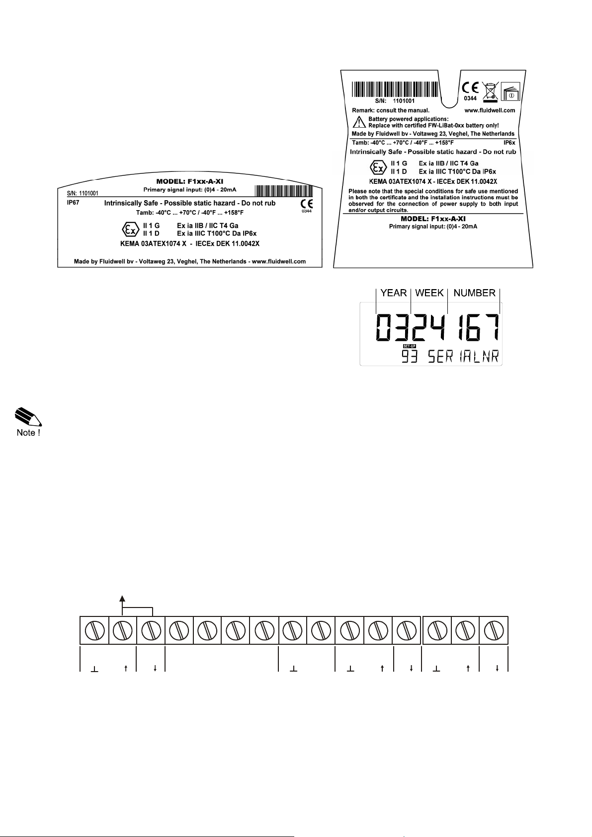
Label information (inside and outside the enclosure)
Indicated labels on the back cover (below) and on the inside
cover (right) show the type labels for intrinsically safe
certified units.
For details on usage see the separate “Fluidwell F1..-..-XI
Documentation for Intrinsic Safety”.
Serial number and year of production
This information can be looked-up on the display:
See setup function (par. 3.2.2.) for details.
5.2. TERMINAL CONNECTORS INTRINSICALLY SAFE APPLICATIONS
The unit is classified as group IIB/IIIC by default.
Classification of the unit as group IIC is only possible under the following conditions:
The indicator is either supplied by
the internal supply (option -PC); or
the external supply connected to terminals 0 and 1 (option -PD); or
the circuit supply connected to terminals 7 and 8 (option -AP);
The maximum values for any of those circuits are those as defined for group IIB/IIIC;
No other active external intrinsically safe circuits may be connected to the indicator, with
exception of circuits connected to terminals 3 and 4 and/or terminals 5 and 6; the maximum
values for any of those circuits are those as defined for group IIB/IIIC
Terminal connectors F151-A-XI:
POWER SUPPLY
OPTION PD:
POWER
SUPPLY
(standard)
2
++
7834 65GND 1
SENSOR A
4-20mA
9101112 1413
+
Fig. 12: Overview terminal connectors Intrinsically Safe.
HF151AEN_v0501_04
SUPPLY
DC
SENSOR B
4-20mA
SUPPLY
DC
+I+I
Page 29

Explanation Intrinsically Safe options:
Option PD-XI
Intrinsically Safe power supply and sensor supply - Terminal GND- 01, 11 and 14.
Page 29
OPTION
PD-XI
Terminal 02, 11 and 14: these terminals offer the same voltage as connected to terminal 01.
Input voltage:
8-30V DC
SENSOR SUPPLY
(TERMINAL 11 AND 14)
GND 01 02
= input voltage L- L+
Terminal
output voltage is according
the input voltage; internally
linked with terminal 01.
HF151AEN_v0501_04
Page 30
Page 30
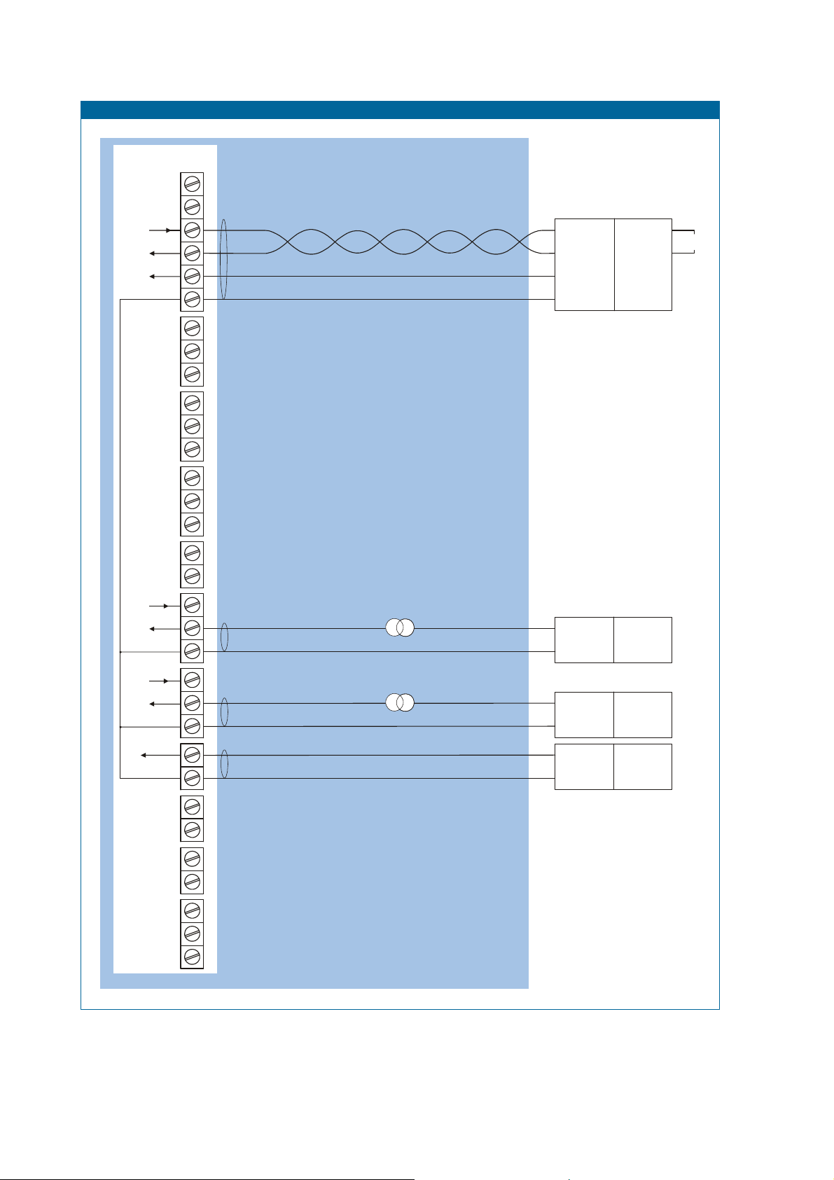
5.3. CONFIGURATION EXAMPLES INTRINSICALLY SAFE APPLICATIONS
Configura tio n e xam p l e IIB - /IIIC F151-A-CT-PX-XI
TERMINAL CONNECTOR S
F100-series
TXD
RXD
28
DTR
27
+12V
Common ground
26 29
Modbus communication type CT: TTL
HAZARDOUS AREA
SAFE AREA
Uo
Io
+
Po
-
= max. 30 V
= max. 250 mA
= max. 0.85 W
I.S. Certified
Isolator
TTL to:
RS232
RS422
TTL
For example:
MTL5051
e.g. PC
Supply *
14
Signal
type of signal
Circuit depends on
Common ground
Circuit depends on
Common ground
Main supply
Common ground
* Note sensor supply voltage: 3.2V DC - not suitable to power analog sensors.
type of signal
Supply *
Signal
12 13
11
910
8
7
Ci is negligibly
small
Ci is negligibly
small
Fig. 13: Configuration example 1 Intrinsically Safe.
Pressure sensor B
Type A: (0)4-20mA
Pressure sensor A
Type A: (0)4-20mA
Power supply type PX:
8-30 V DC
+
= max. 30 V
Uo
= max. 100 mA
Io
-
= max. 0.75 W
Po
+
= max. 30 V
Uo
= max. 100 mA
Io
-
= max. 0.75 W
Po
+
= max. 30 V
Uo
= max. 100 mA
Io
-
= max. 0.75 W
Po
Note: above values are safety values.
Consult the technical specification for operational values.
Power supply
For example
MTL5525
Power supply
For example
MTL5525
Power supply
For example
MTL5525
HF151AEN_v0501_04
Page 31
Page 31
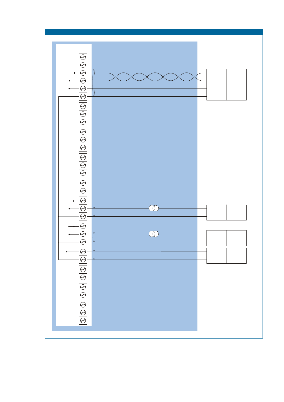
Configura tio n e xam p l e IIB - /IIIC F151-A-CT-PX-XI
TERMINAL CONNECTOR S
F100-series
TXD
RXD
28
DTR
27
+12V
Common ground
26 29
Modbus communication type CT: TTL
HAZARDOUS AREA
SAFE AREA
Uo
Io
+
Po
-
= max. 30 V
= max. 250 mA
= max. 0.85 W
I.S. Certified
Isolator
TTL to:
RS232
RS422
TTL
For example:
MTL5051
e.g. PC
Supply *
14
Signal
type of signal
Circuit depends on
Common ground
Circuit depends on
Common ground
Main supply
Common ground
* Note sensor supply voltage: 3.2V DC - not suitable to power analog sensors.
type of signal
Supply *
Signal
12 13
11
910
8
7
Ci is negligibly
small
Ci is negligibly
small
Pressure sensor B
Type A: (0)4-20mA
Pressure sensor A
Type A: (0)4-20mA
Power supply type PX:
8-30 V DC
+
= max. 30 V
Uo
= max. 100 mA
Io
-
= max. 0.75 W
Po
+
= max. 30 V
Uo
= max. 100 mA
Io
-
= max. 0.75 W
Po
+
= max. 30 V
Uo
= max. 100 mA
Io
-
= max. 0.75 W
Po
Note: above values are safety values.
Consult the technical specification for operational values.
Power supply
For example
MTL5525
Power supply
For example
MTL5525
Power supply
For example
MTL5525
Fig. 14: Configuration example 2 Intrinsically Safe.
HF151AEN_v0501_04
Page 32
Page 32
5.4 BATTERY REPLACEMENT INSTRUCTIONS
Safety Instructions
Fire, explosion or severe burns may result if mistreated. Do not recharge, crush,
disassemble, incinerate, heat above 100°C (212°F) or expose contents to water.
Mounting, electrical installation, start-up and maintenance of this device may only be carrie d out
by trained personnel authorized by the plant operator. Personnel must read and understand this
instruction before carrying out the replacement procedure.
Always follow the instructions listed in the supplied Battery Replacement Instruction Sheet.
Batteries pose an environmental hazard. Return used batteries to a recycling point.
Safety instructions for hazardous areas
Verify the correct battery is supplied: Only batteries with indicated Ex label are certified for
replacement and use in hazardous areas. Batteries for use in safe areas have no Ex label.
DO NOT EXCHANGE: Using the wrong type of battery can pose a SERIOUS RISK.
For use in hazardous areas Fluidwell recommends FW-LiBAT type batteries
(manufactured by Fluidwell bv) only.
Battery replacement procedure
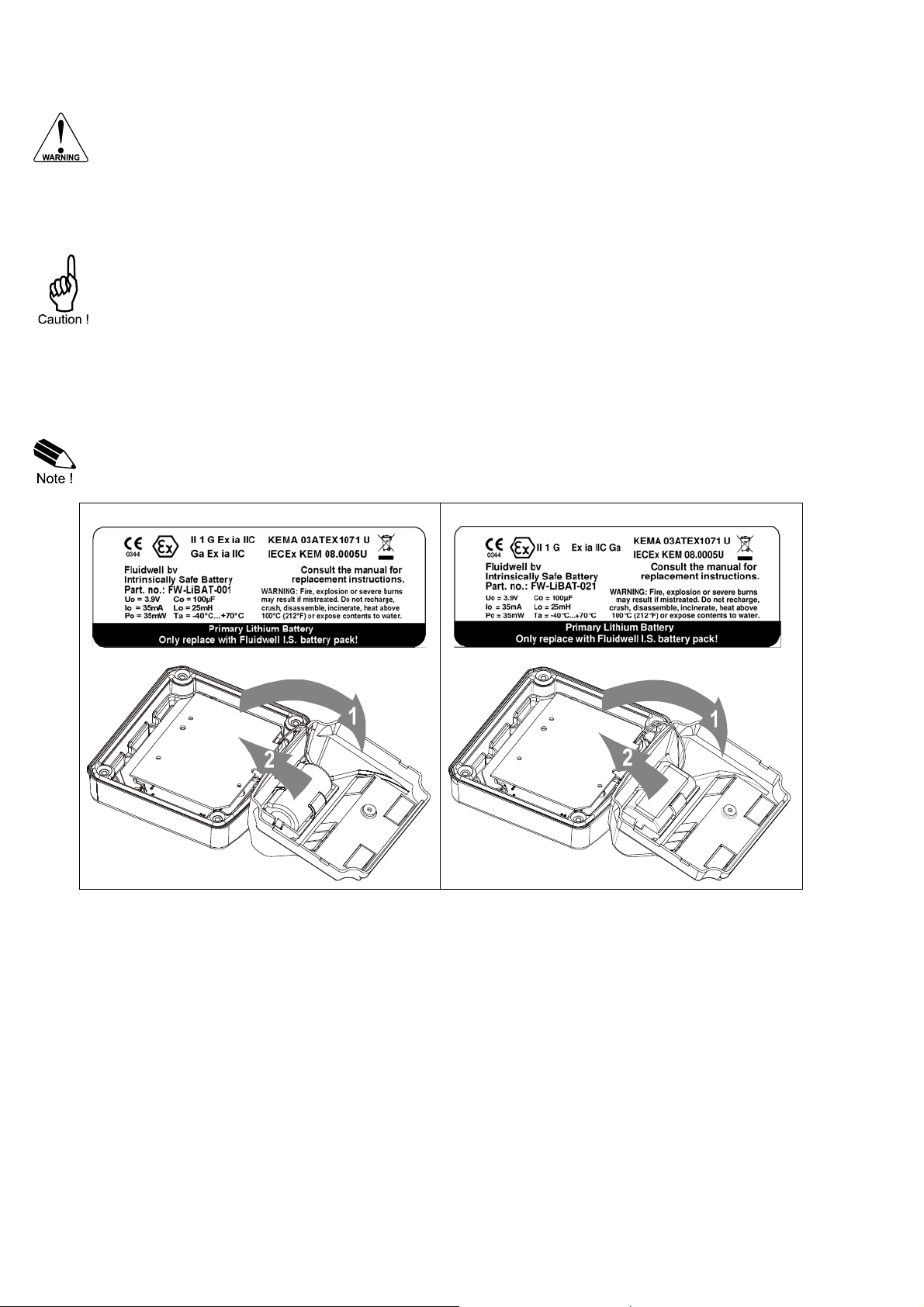
Depending on the production batch, one of two visualized Intrinsically Safe ce rtified battery
types may have been installed in the unit. They are interchangeable .
FW-LiBAT-001 battery FW-LiBAT-021 battery
1. To replace the battery, open the unit to gain access to the back inside cover of the unit
2. Unplug the field connectors from the back inside of the unit.
3. Remove the screw that holds the plastic inside cover.
4. Open the cover and unplug the battery connector.
5. Remove the battery from the inside of the plastic cover. Do not remove the battery clip!
6. Install the new battery and re-assemble the unit in reverse order.
7. Start-up the unit
HF151AEN_v0501_04
Page 33

Page 33
6. MAINTENANCE
6.1. GENERAL DIRECTIONS
Mounting, electrical installation, start-up and maintenance of the instrument may only
be carried out by trained personnel authorized by the operator of the facility. Personnel
must read and understand this Operating Manual before carrying out its instructions.
The F151-A may only be operated by personnel who are authorized and trained by the
operator of the facility. All instructions in this manual are to be observed.
Ensure that the measuring system is correctly wired up according to the wiring
diagrams. Protection against accidental contact is no longer assured when the housing
cover is removed or the panel cabinet has been opened (danger from electrical shock).
The housing may only be opened by trained personnel.
Take careful notice of the " Safety rules, instructions and precautionary measures " in
the front of this manual.
The F151-A does not require special maintenance unless it is used in low-temperature applications
or surroundings with high humidity (above 90% annual mean). It is the users responsibility to take all
precautions to dehumidify the internal atmosphere of the F151-A in such a way that no condensation
will occur, for example by placing dry silica-gel sachet in the casing just before closing it.
Furthermore, it is required to replace or dry the silica gel periodically as advised by the silica gel
supplier.
Battery life-time:
It is influenced by several issues as:
Display update: fast display update has major influence; SETUP 61.
communication.
Low temperatures; the available power will be less due to battery chemistry.
Note: It is strongly advised to disable unused functions.
Check periodically:
The condition of the casing, cable glands and front panel.
The input/output wiring for reliability and aging symptoms.
The process accuracy. As a result of wear and tear, re-calibration of the sensor might be
necessary. Do re-enter any subsequent Span alterations.
The indication for low-battery.
Clean the casing with soapy-water; don't use any aggressive solvents as these might damage
the polyester coating.
HF151AEN_v0501_04
Page 34
Page 34
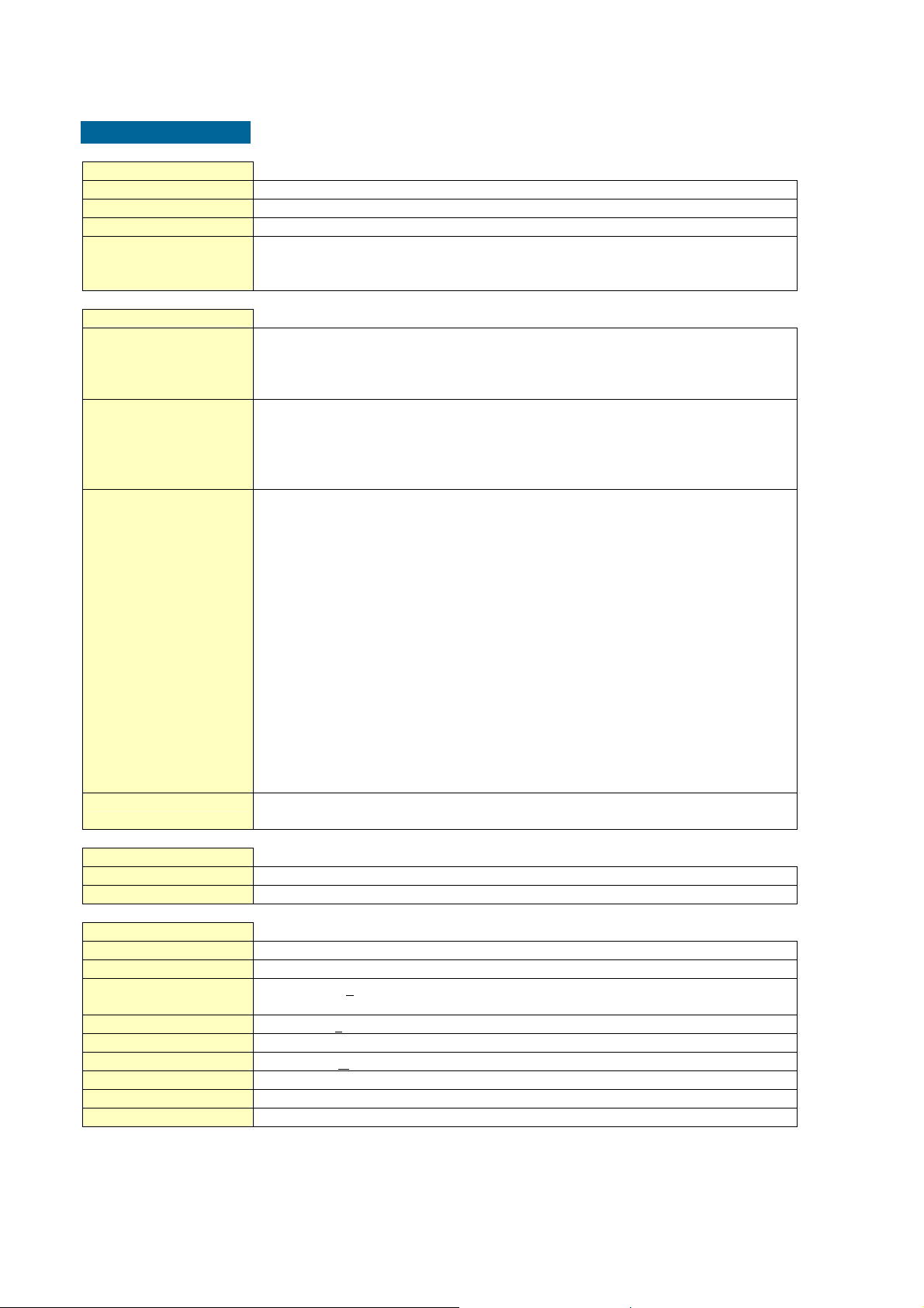
APPENDIX A: TECHNICAL SPECIFICATION
GENERAL
Display
Type High intensity reflective numeric and alphanumeric LCD, UV-resistant.
Digits Seven 17mm (0.67") and eleven 8mm (0.31"). Various symbols and measuring units.
Refresh rate User definable: 8 times/sec - 30 secs.
Type ZB Transflective LCD with green LED backlight. Good readings in full sunlight and darkness.
Enclosures
General
Control Keys
Painting
Panel-mount enclosures
Classification
Panel cut-out
Type HC
Type HB
Field/wall-mount enclosures
Classification
Aluminum enclosures
Type HA
Type HM
Type HN
Type HO
Type HP
Type HT
Type HU
Type HZ
GRP enclosures
Type HD
Type HE
Type HF
Type HG
Type HH
Option ZS Silicone free ABS enclosure with EPDM and PE gaskets. UV-resistant polyester keypad.
Operating temperature
Operational -40°C to +80°C (-40°F to +176°F)
Intrinsically Safe -40°C to +70°C (-40°F to +158°F)
Power supply
Type PB Lithium battery - life-time depends upon settings - up to 5 years.
Type PC Intrinsically Safe lithium battery - life-time depends upon settings - up to 5 years.
Type PD 8-24V AC / DC + 10%. Power consumption max. 10 Watt.
Type PF 24V AC / DC + 10%. Power consumption max. 15 Watt.
Type PL Input loop powered from sensor signal 4-20mA (type A, non IS).
Type PM 115-230V AC + 10%. Power consumption max. 15 Watt.
Type PX Output loop powered: 8-30V DC. Power consumption max. 0.5 Watt.
Note PF / PM The total consumption of the sensors`, backlight and outputs may not exceed 400mA@24V.
Note I.S. applications For intrinsically safe applications, consult the safety values in the certificate.
Note: only available for safe area applications.
Power requirements: 12-24V DC + 10% or type PD, PF, PM. Power consumption max. 1 Watt.
Die-cast aluminum or GRP (Glassfibre Reinforced Polyamide) enclosure with Polycarbonate
window, silicone and EPDM gaskets. UV stabilized and flame retardant material.
Three industrial micro-switch keys. UV-stabilized silicone keypad.
Aluminum enclosure only: UV-resistant 2-component industrial painting.
Dimensions: 130 x 120 x 60mm (5.10" x 4.72" x 2.38") – LxHxD.
IP65 / NEMA4X
115 x 98mm (4.53" x 3.86") LxH.
GRP panel-mount enclosure
Aluminum panel-mount enclosure
Dimensions: 130 x 120 x 75mm (5.10” x 4.72” x 2.95”) – LxHxD.
IP67 / NEMA4X
Drilling: 2x PG9 – 1x M20.
Drilling: 2x M16 – 1x M20.
Drilling: 1x M20.
Drilling: 2x M20.
Drilling: 6x M12.
Drilling: 1x ½”NPT.
Drilling: 3x ½”NPT.
No drilling.
No drilling.
Drilling: 2x 16mm (0.63”) – 1x 20mm (0.78”).
Drilling: 1x 22mm (0.87”).
Drilling: 2x 20mm (0.78”).
Drilling: 6x 12mm (0.47”).
Note: this option comes with type HD only.
Intrinsically safe: 16-30V DC; power consumption max. 0.75 Watt.
HF151AEN_v0501_04
Page 35
Sensor excitation
Type PB / PC / PX 3.2V DC for pulse signals and 1.2V DC for coil pick-up.
Note: This is not a real sensor supply. Only suitable for pulse sensors with a very low power
consumption like coils (sine wave) and reed-switches.
Type PD 1.2 - 3.2 - 8.2 - 12 and 24V DC - max. 50mA@24V DC
Type PD-XI Intrinsically safe: Pulse signals: 1.2 - 3.2 - 8.2 - max. [email protected] DC.
Analog signals: the sensor supply voltage is according to the power supply voltage connected
to terminal 1. Also terminal 2 offers the same voltage.
Type PF / PM 1.2 - 3.2 - 8.2 - 12 and 24V DC - max. 400mA@24V DC.
Terminal connections
Type: Removable plug-in terminal strip. Wire max. 1.5mm2 and 2.5mm2 (Type PM / PF)
Data protection
Type EEPROM backup of all setting. Backup of running totals every minute.
Data retention at least 10 years.
Pass code Configuration settings can be pass code protected.
Hazardous area
(option)
Intrinsically safe
Type XI
ATEX approval:
II 1 G Ex ia IIB/IIC T4 Ga
II 1 D Ex ia IIIC T100°C Da IP6x
IECEx approval:
Ex ia IIB/IIC T4 Ga
Ex ia IIIC T100°C Da IP6x
Explosion proof
Type XD/XF
ATEX approval ref.: <EX> II 2 GD EEx d IIB T5. Weight appr. 15kg.
Dimensions of enclosure: 350 x 250 x 200mm (13.7” x 9.9” x 7.9”) LxHxD.
Environment
Electromagnetic
Compliant ref: EN 61326 (1997), EN 61010-1 (1993).
compatibility
Page 35
INPUTS
Sensor
Type A (0)4-20mA - with signal calibration feature. Resolution: 14 bit.
Type U 0-10 V, 0-5 V, 1-5 V - with signal calibration feature. Resolution: 14 bit.
Accuracy 0.05%. Low level cut-off programmable.
Span 0.000010 - 9,999,999 with variable decimal position.
Update time Four times a second.
Voltage drop type A 2.5 Volt.
Load impedance type U 3kOhm
Relationship Linear and square root calculation.
Note For signal type A and U: external power to sensor required; e.g. option PD.
OUTPUTS
Communication option
Type RS232 or RS485 (2-wire or 4-wire).
Protocol Modbus ASCII / RTU
Speed 1200 - 2400 - 4800 - 9600 baud
Addressing maximum 255 addresses.
Functions reading display information, reading / writing all settings.
HF151AEN_v0501_04
Page 36

Page 36
OPERATIONAL
Operator functions
Displayed functions
• pressure line A
• pressure line B
Both pressure’s can be displayed simultaneously or separately by manual operation or
automatic toggle function.
Pressure A and B
Digits 5 digits.
Units BAR - mbar - PSI - no unit
Decimals 0 - 1 - 2 or 3.
HF151AEN_v0501_04
Page 37

Page 37
APPENDIX B: PROBLEM SOLVING
In this appendix, several problems are included that can occur when the F151 -A is going to be
installed or while it is in operation.
The password is unknown:
If the password is not 1234, there is only one possibility left: call your supplier.
ALARM
When the alarm flag starts to blink an internal alarm condition has occurred. Press the " sele ct
button" several times to display the 5-digit error code. The codes are:
0001: irrecoverable display-data error: data on the display might be corrupted.
0002: irrecoverable data-storage error: the programming cycle might have gone wrong: check
programmed values.
0003: error 1 and error 2 occurred simultaneously
The alarm condition will almost certainly be handled internally and if all mentioned values still appear
correct, no intervention by the operator is needed. If the alarm occurs more often or stays active for
a longer time, please contact your supplier.
HF151AEN_v0501_04
Page 38
Page 38
APPENDIX C: COMMUNICATION VARIABLES
Remarks:
Below, an overview of the F151-A specific variables; other common variables are described in
the standard table.
All numbers are decimal numbers, unless otherwise noted.
Following variables of the standard table (var00-var30) are not valid for this product and will be
responded with value 1: var00, 03-05, 07,08, 16-22, 24, 26-29.
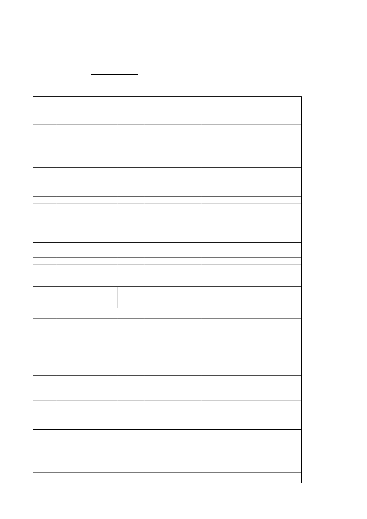
CONFIGURATION VARIABLES F151-A - SETUP-LEVEL:
VAR DESCRIPTION BYTES VALUE REMARKS
PRESSURE A
48
unit 1 0=mbar
(30h)
50
decimals 1 0…1
(32h)
51
Span 3 1....99.999
(33h)
54
decimals Span 1 0…5
(36h)
offset
PRESSURE B
unit 1 0=mbar
decimals 1 0…1
Span 3 1....99.999
decimals Span 1 0…5
offset
DISPLAY
195
(C3h)
POWERMANAGEMENT
80
(50h)
81
(51h)
SENSOR A
98
(62h)
99
(63h)
100
(64h)
102
(66h)
103
(67h)
display 1 0=toggle
LCD update time 1 0=fast
power-mode battery 1 0=operational
formula 1 0=linear
filter 1 0….99
cut-off 2 0….999 steps of 0.1%
calibration low
(4mA)
calibration high
(20mA)
1 0=default
1 0=default
1=bar
2=psi
3=none
1=bar
2=psi
3=none
1=hand
2=A and B
1=1sec
2=3sec
3=15sec
4=30sec
5=off
1=shelf
1=square root
1=calibrate
2=cal set
1=calibrate
2=cal set
SENSOR B
HF151AEN_v0501_04
Page 39

Page 39
formula 1 0=linear
1=square root
filter 1 0….99
cut-off 2 0….999 steps of 0.1%
calibration low
(4mA)
1 0=default
1=calibrate
2=cal set
calibration high
(20mA)
1 0=default
1=calibrate
2=cal set
OTHERS
168
password 2 xxxx read only!
(A8h)
170
tagnumber 3 0..9999999 Other vars: see standard table
AAh
OTHER F151-A VARIABLES FOR COMMUNICATION
READ PRESSURE: The value of pressure read using communication might differ from the value
displayed. This is due to the fact that the display can only display up to seven digits
(e.g. when two decimals are selected for pressure and pressure has a value of
123456,78 the display will show 23456,78 while communication will read a
“pressure” of 12345678 and a “pressure decimals” of 2).
WRITE PRESSURE: Impossible.
Pressure A - variable number 572 (23Ch) – 4 bytes
Pressure B - variable number 588 (24Ch) – 4 bytes
HF151AEN_v0501_04
Page 40
Page 40
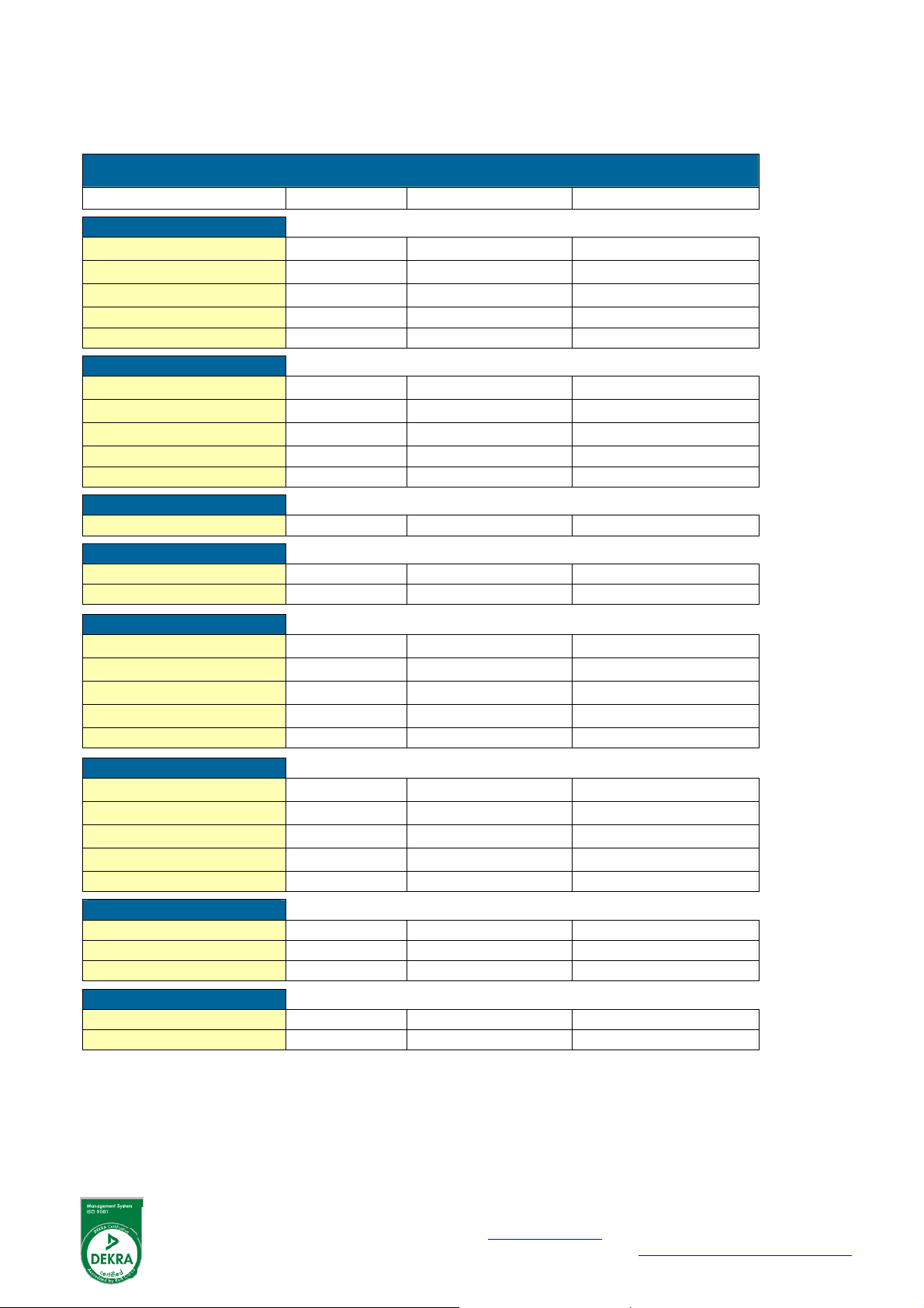
LIST OF CONFIGURATION SETTINGS
1 - PRESSURE A
11 unit
12 decimals
13 span
14 decimals span 0
15 offset 0
2 - PRESSURE B
21 unit
22 decimals
23 span
24 decimals span 0
25 offset 0
3 - DISPLAY
31 display toggle
4 - POWER MANAGEMENT
41 LCD-new 1 sec.
42 mode operational
5 - SENSOR - A
51 formula
52 filter
53 cut-off %
54 calibrate low-(0)4mA
55 calibrate high-20mA
6 - SENSOR - B
61 formula
62 filter
63 cut-off %
64 calibrate low-(0)4mA
65 calibrate high-20mA
7 - COMMUNICATION
71 baud-rate 2400
72 address 1
73 mode off
8 - OTHERS
84 password 0000
85 tagnumber 0000000
SETTING DEFAULT DATE : DATE :
BAR
00000
00001
BAR
00000
00001
interpolation
01 (off)
00.0%
default
default
interpolation
01 (off)
00.0%
default
default
Fluidwell bv
PO box 6 Voltaweg 23 Website: www.fluidwell.com
5460 AA Veghel 5466 AZ Veghel Find your nearest represe ntative: www.fluidwell.com/representatives
The Netherlands The Netherlands Copyright Fluidwell bv - 2012 - HF110AEN_v0501_03
HF151AEN_v0501_04
 Loading...