

Page 1
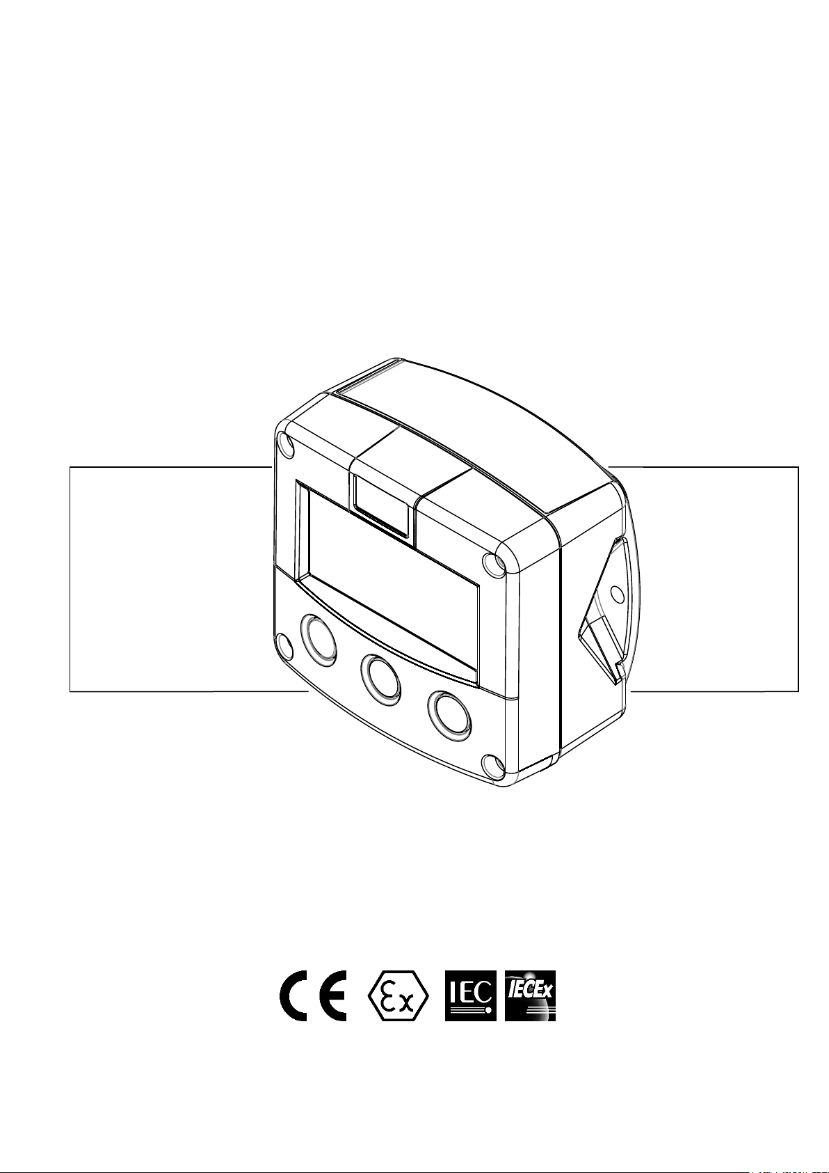
F-Series - Field mounted indicators for safe and hazardous areas.
More info: www.fluidwell.com/fseries
F112-A
FLOWRATE INDICATOR / TOTALIZER
WITH LINEARIZATION
Signal input flowmeter: (0)4-20mA
Signal outputs: 4-20mA ref. flowrate and pulse ref. total.
Options: Intrinsically safe, Modbus communication, external reset and
backlight.
Page 2

Page 2
SAFETY INSTRUCTIONS
Any responsibility is lapsed if the instructions and procedures as described in this
manual are not followed.
LIFE SUPPORT APPLICATIONS: The F112-A is not designed for use in life support
appliances, devices, or systems where malfunction of the product can reasonably be
expected to result in a personal injury. Customers using or selling these products for use
in such applications do so at their own risk and agree to fully indemnify the manufacturer
and supplier for any damages resulting from such improper use or sale.
Electro static discharge does inflict irreparable damage to electronics! Before installing
or opening the unit, the installer has to discharge himself by touching a well-grounded
object.
This unit must be installed in accordance with the EMC guidelines (Electro Magnetic
Compatibility).
Do connect a proper grounding to the metal enclosure as indicated if the F112-A has an
incoming power line which carries a 115-230V AC. The Protective Earth (PE) wire may
never be disconnected or removed.
Intrinsically safe applications: follow the instructions as mentioned in Chapter 5 and
consult “Fluidwell F1..-..-XI - Documentation for Intrinsic safety”.
DISPOSAL OF ELECTRONIC WASTE
The WEEE Directive requires the recycling of disposed electrical and electronic equipment in the
European Union. When the WEEE Directive does not apply to your region, we support its policy
and ask you to be aware on how to dispose of this product.
The crossed out wheelie bin symbol as illustrated and found on our products tells that this
product shall not be disposed of into the general waste system or into a landfill.
At the end of its life, equipment shall be disposed of according to the local regulations regarding
waste of the electrical and the electronic equipment.
Please contact your local dealer, national distributor or the manufacturer’s Technical helpdesk for
information on the product disposal.
SAFETY RULES AND PRECAUTIONARY MEASURES
The manufacturer accepts no responsibility whatsoever if the following safety rules and
precautions instructions and the procedures as described in this manual are not followed.
Modifications of the F112-A implemented without preceding written consent from the
manufacturer, will result in the immediate termination of product liability and warranty period.
Mounting, electrical installation, start-up and maintenance of this device may only be carried out
by trained persons authorized by the operator of the facility. Persons must read and understand
this manual before carrying out its instructions.
This device may only be operated by persons who are authorized and trained by the operator of
the facility. All instructions in this manual are to be observed.
Check the mains voltage and information on the manufacturer's plate before installing the unit.
Check all connections, settings and technical specifications of the various peripheral devices
with the F112-A supplied.
Open the enclosure only if all leads are free of potential.
Never touch the electronic components (ESD sensitivity).
Never expose the system to heavier conditions than allowed according the classification of the
enclosure (see manufacture's plate and chapter 4).
If the operator detects errors or dangers, or disagrees with the safety precautions taken, then
inform the owner or principal responsible.
The local labor and safety laws and regulations must be adhered to.
FW_F112A_v1702_02_EN
Page 3
Page 3
A "warning !" indicates actions or procedures which, if not performed correctly, may lead to
personal injury, a safety hazard or damage of the F112-A or connected instruments.
A "caution !" indicates actions or procedures which, if not performed correctly, may lead to
personal injury or incorrect functioning of the F112-A or connected instruments.
A "note !" indicates actions or procedures which, if not performed correctly, may indirectly
affect operation or may lead to an instrument response which is not planned.
Hardware version : 03.01.xx
Software version : 03.04.xx
Manual : FW_F112A_v1702_02_EN
© Copyright 2017 : Fluidwell B.V. - the Netherlands
Information in this manual is subject to change without prior notice. The
manufacturer is not responsible for mistakes in this material or for incidental
damage caused as a direct or indirect result of the delivery, performance or
use of this material.
© All rights reserved. No parts of this publication may be reproduced or used
in any form or by any means without written permission of your supplier.
ABOUT THE MANUAL
This manual is divided into two main sections:
The daily use of the unit is described in chapter 2 "Operation". These instructions are meant for
users.
The following chapters and appendices are exclusively meant for electricians/technicians. These
provide a detailed description of all software settings and hardware installation guidance.
This manual describes the standard unit as well as the available options. For additional information,
please contact your supplier.
A hazardous situation may occur if the F112-A is not used for the purpose it was designed for
or is used incorrectly. Please carefully note the information in this operating manual
indicated by the pictograms:
WARRANTY AND TECHNICAL SUPPORT
For warranty and technical support for your Fluidwell products,
visit our internet site www.fluidwell.com or contact us at [email protected].
FW_F112A_v1702_02_EN
Page 4

Page 4
CONTENTS MANUAL
Safety instructions ................................................................................................................................ 2
Disposal of electronic waste ................................................................................................................. 2
Safety rules and precautionary measures ............................................................................................ 2
About the manual .................................................................................................................................. 3
Warranty and technical support ............................................................................................................ 3
Contents manual ................................................................................................................................... 4
1. Introduction .................................................................................................................... 5
1.1. System description ........................................................................................................ 5
2. Operational .................................................................................................................... 6
2.1. Control panel ................................................................................................................. 6
2.3. Operator information and functions ............................................................................... 7
3. Configuration ................................................................................................................. 8
3.1. How to program the F112-A .......................................................................................... 8
3.1.1. Setup menu - Settings ................................................................................................. 10
3.1.2. Explanation of SETUP-menu 1 - Total ........................................................................ 11
3.1.3. Explanation of SETUP-menu 2 - Flow rate ................................................................. 11
3.1.4. Explanation of SETUP-menu 3 - Display .................................................................... 12
3.1.5. Explanation of SETUP-menu 4 - Power management ................................................ 12
3.1.6. Explanation of SETUP-menu 5 - Flowmeter ............................................................... 12
3.1.7. Explanation of Setup menu 6 - Linearize .................................................................... 13
3.1.8. Explanation of SETUP menu 7 - Analog ..................................................................... 14
3.1.9 Explanation of SETUP menu 8 - Pulse ....................................................................... 15
3.1.10. Explanation of SETUP-menu 9 - Communication (option) .................................... 16
3.1.11. Explanation of SETUP-menu A - Others ............................................................... 16
4. Installation .................................................................................................................... 17
4.1. General directions ....................................................................................................... 17
4.2. Installation / surrounding conditions ............................................................................ 17
4.3. Dimensions- Enclosure ................................................................................................ 18
4.4. Installing the hardware ................................................................................................ 20
4.4.1. General installation guidelines..................................................................................... 20
4.4.2. Aluminum enclosure - Field mounted .......................................................................... 21
4.4.3. Aluminum enclosure - Panel mounted ........................................................................ 21
4.4.4. Plastic (GRP) enclosure .............................................................................................. 22
4.4.5. Terminal connectors .................................................................................................... 23
4.4.6. Sensor supply .............................................................................................................. 23
5. Intrinsically safe applications ....................................................................................... 29
5.1. General information and instructions ........................................................................... 29
5.2. Terminal connectors Intrinsically safe applications ..................................................... 31
5.3. Configuration examples Intrinsically safe applications ................................................ 33
5.4 Battery replacement instructions ................................................................................. 35
5.4.1. Safety instructions ....................................................................................................... 35
5.4.2. Replace the battery (hazardous area) ......................................................................... 35
5.4.3. Disposal of batteries .................................................................................................... 35
6. Maintenance ................................................................................................................ 36
6.1. General directions ....................................................................................................... 36
6.2. Repair .......................................................................................................................... 36
6.3. Repair policy ................................................................................................................ 36
Appendix A: Technical specification ................................................................................................ 37
Appendix B: Problem solving ........................................................................................................... 40
Appendix C: Communication variables ............................................................................................ 41
Appendix D: Declaration of Conformity ............................................................................................ 44
Index of this manual ............................................................................................................................ 45
List of figures in this manual ............................................................................................................... 45
FW_F112A_v1702_02_EN
Page 5
Page 5
1. INTRODUCTION
1.1. SYSTEM DESCRIPTION
Functions and features
The flow rate / totalizer model F112-A is a microprocessor driven instrument designed to display the
flow rate, the total and the accumulated total.
This product has been designed with a focus on:
ultra-low power consumption to allow long-life battery powered applications (type PB/PC);
intrinsic safety for use in hazardous applications (type XI),
ability to process all types of flowmeter signals;
transmitting possibilities with analog, pulse and communication outputs;
several mounting possibilities with GRP or aluminum enclosures for industrial surroundings.
Flowmeter input
This manual describes the unit with a (0)4-20mA input from the flowmeter. Other versions are
available to process pulse signals.
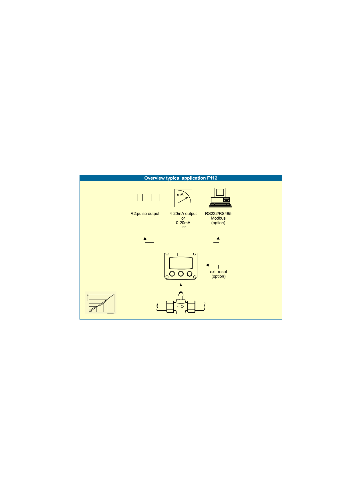
One flowmeter with a (0)4-20mA output can be connected to the F112-A. To power the sensor,
several options are available.
Standard outputs
Pulse output to transmit a pulse that represents a linearized totalized quantity as programmed.
Linear (0)4-20mA or 0-10V analog output to represent the actual flow rate as programmed. The
(0)4-20mA or 0-10V signal limits can be tuned.
Fig. 1: Typical application
Configuration
The F112-A is designed for use in many types of applications. For that reason, a setup menu is
available to program the F112-A according to your specific requirements.
The setup includes several important features, such as span, engineering units, signal selection,
power management (to extend battery life-time), etc. All settings are stored in a non-volatile memory
and therefore kept in the event of a power failure or an exhausted battery.
Display information
The unit has a LCD with (optional) backlight to show the process information, status and alarm messages.
The display refresh rate is programmed in the setup menu.
At a key press, the display refresh rate will switch to FAST for 30 seconds. When 'OFF' is selected,
the display goes off after 30 seconds after the last key press. The display temporarily comes on after
a key press.
A backup of the total and accumulated total in EEPROM memory is made every minute.
Options
The following options are available: isolated or active (0)4-20mA / 0-10V analog output, full Modbus
communication RS232/485/TTL (also battery powered), intrinsic safety, mechanical relay or active
output, power- and sensor-supply options, panel -mount, wall-mount and weather-proof enclosures,
flame proof enclosure and LED backlight.
FW_F112A_v1702_02_EN
Page 6
Page 6
This device may only be operated by persons who are authorized and trained by the
operator of the facility. All instructions in this manual are to be observed.
Take careful notice of the "Safety rules, instructions and precautionary measures" in the
front of this manual.
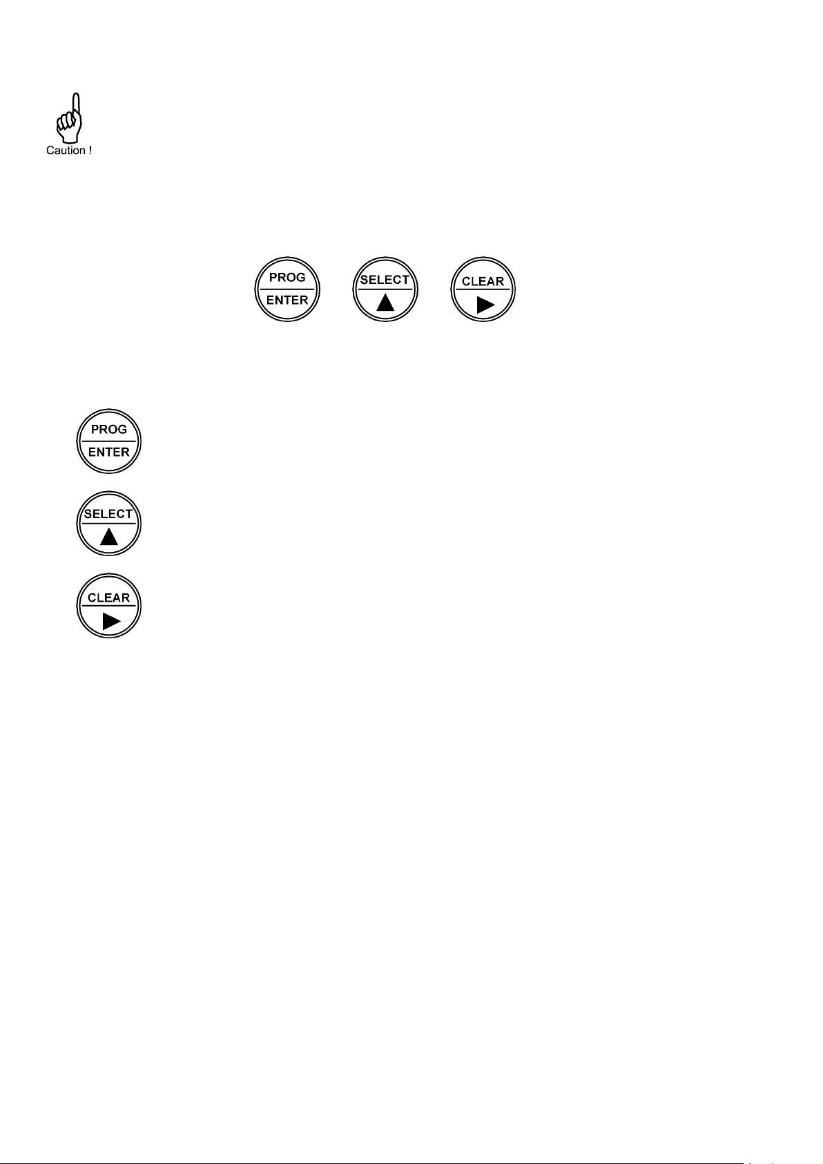
This key is used to program and save new values or settings.
The PROG/ENTER key is also used to gain access to the setup menu (read
chapter 3).
This key is used to select the accumulated total and the temperature.
The SELECT/ key is also used to increase a value after the PROG/ENTER key has
been pressed (read chapter 3).
This key is used to reset the total.
The CLEAR/ key is also used to select a digit or an option after the PROG/ENTER
key has been pressed (read chapter 3).
2. OPERATIONAL
This chapter describes the daily use of the F112-A. This instruction is meant for users / operators.
2.1. CONTROL PANEL
The control panel has three keys. The available keys are:
Fig. 2: Control Panel
Functions of the keys
FW_F112A_v1702_02_EN
Page 7
Page 7
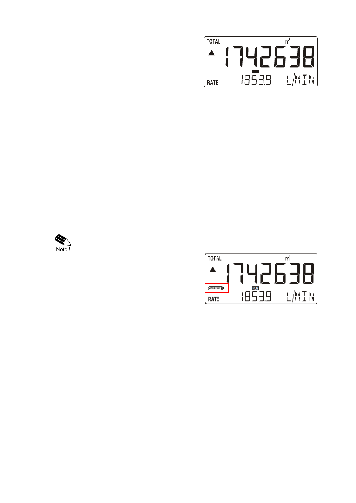
In general, the F112-A operates in the operator
mode. The shown information depends on the
settings which are made in the setup menu.
The signal from the connected sensor is processed
by the F112-A in the background, independent from
the selected display refresh rate.
Fig. 3: Process information (typical)
Only use original batteries. Original batteries can be ordered at the manufacturer.
The use of unapproved batteries will void the warranty.
At the end of the battery’s life-time, the
voltage starts to drop. When the voltage
becomes too low, the battery indicator comes
on. When the battery indicator is on, install a
new and fresh battery as soon as possible.
Fig. 4: Low-battery alarm (typical)
RUN
2.3. OPERATOR INFORMATION AND FUNCTIONS
For the Operator, the following functions are available:
Display (linearized) flow rate / total or flow rate
This is the main display information of the F112-A . After the selection of any other information, it
will always return to this main display automatically. Total is shown on the upper line of the
display and flow rate on the bottom line. When selected in the setup menu, the display shows the
flow rate only. When you press the select key, the total shows momentarily.
Clear total
The value for total can be reset. To do so, press the CLEAR/ key twice. When the key is
pressed once, the text "PUSH CLEAR" is shown. To avoid a reset at this stage, press another
key other than the CLEAR/ key or wait for 20 seconds. A reset of the total does not influence
the accumulated total.
Type IB: When a Normally Closed (NC) contact is used, the local clear total function is
disabled and a clear total is only possible with the external reset command.
Display (linearized) accumulated total
When the SELECT/ key is pressed, total and accumulated total are shown. The accumulated
total cannot be reset. The value will count up to 99,999,999,999. The unit and number of
decimals are shown according to the settings for the total.
Low-battery alarm
Alarm
When the alarm indicator is shown, refer to Appendix B: Problem Solving.
FW_F112A_v1702_02_EN
Page 8
Page 8
Mounting, electrical installation, start-up and maintenance of this device may only be
carried out by trained persons authorized by the operator of the facility. Persons must
read and understand this manual before carrying out its instructions.
This device may only be operated by persons who are authorized and trained by the
operator of the facility. All instructions in this manual are to be observed.
Make sure, the measuring system is correctly wired up according to the wiring diagrams.
Protection against accidental contact is no longer assured when the housing cover is
removed or the panel cabinet has been opened (danger from electrical shock). The
housing may only be opened by trained persons authorized by the operator of the facility.
Take careful notice of the "Safety rules, instructions and precautionary measures" in the
front of this manual.
It is possible to prevent access to the SETUP menu with a password. A password may be
required to enter the SETUP menu. Without this password, access to SETUP is denied.
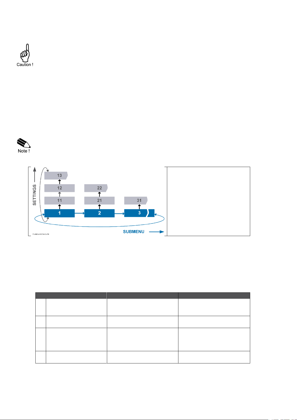
The setup menu has different
submenus. Each submenu has an
unique number which is shown in
front of the menu name.
Each setting has an unique twodigit number which is shown in
front of the setting. The first digit
refers to the submenu and the
second digit refers to the setting.
Note that sometimes the name of
the setting is shown on the upper
line of the display.
Action
Result
Remark
1
Press the CLEAR/► key
to select the next
submenu.
The submenu FLOW
RATE shows
2
Press again to go to the
next submenu.
The submenu DISPLAY
shows.
-
3
Momentarily, press the
PROG/ENTER key to
select the previous
submenu.
The submenu FLOW
RATE shows
The PROG/ENTER key is
used as a ◄ key.
4
Press again to go to the
previous submenu.
The submenu TOTAL
shows
The PROG/ENTER key is
used as a ◄ key.
3. CONFIGURATION
This and the following chapters are exclusively meant for electricians and non-operators. In these,
an extensive description of all software settings and hardware connections are provided.
The setup menu is used to program the F112-A .
The setup menu is accessible at all times while the F112-A remains fully operational. Be aware that
in this case any change to the settings may have an influence on the operation.
3.1. HOW TO PROGRAM THE F112-A
How to enter the setup menu
When the setup menu is protected by a password, the F112-A asks for a password to access the
setup menu. When in the operator mode, press and hold the PROG/ENTER key for 7 seconds to
access the setup menu.
How to navigate in the setup menu
The setup menu has different submenus to program the F112-A . For navigation, the submenus
and the settings are identified with numbers (for the submenu: e.g. 1; for the setting: e.g. 12.).
The CLEAR/► key and the PROG/ENTER key are used for navigation. The explanation
assumes that you are in the submenu TOTAL.
FW_F112A_v1702_02_EN
Page 9
Page 9
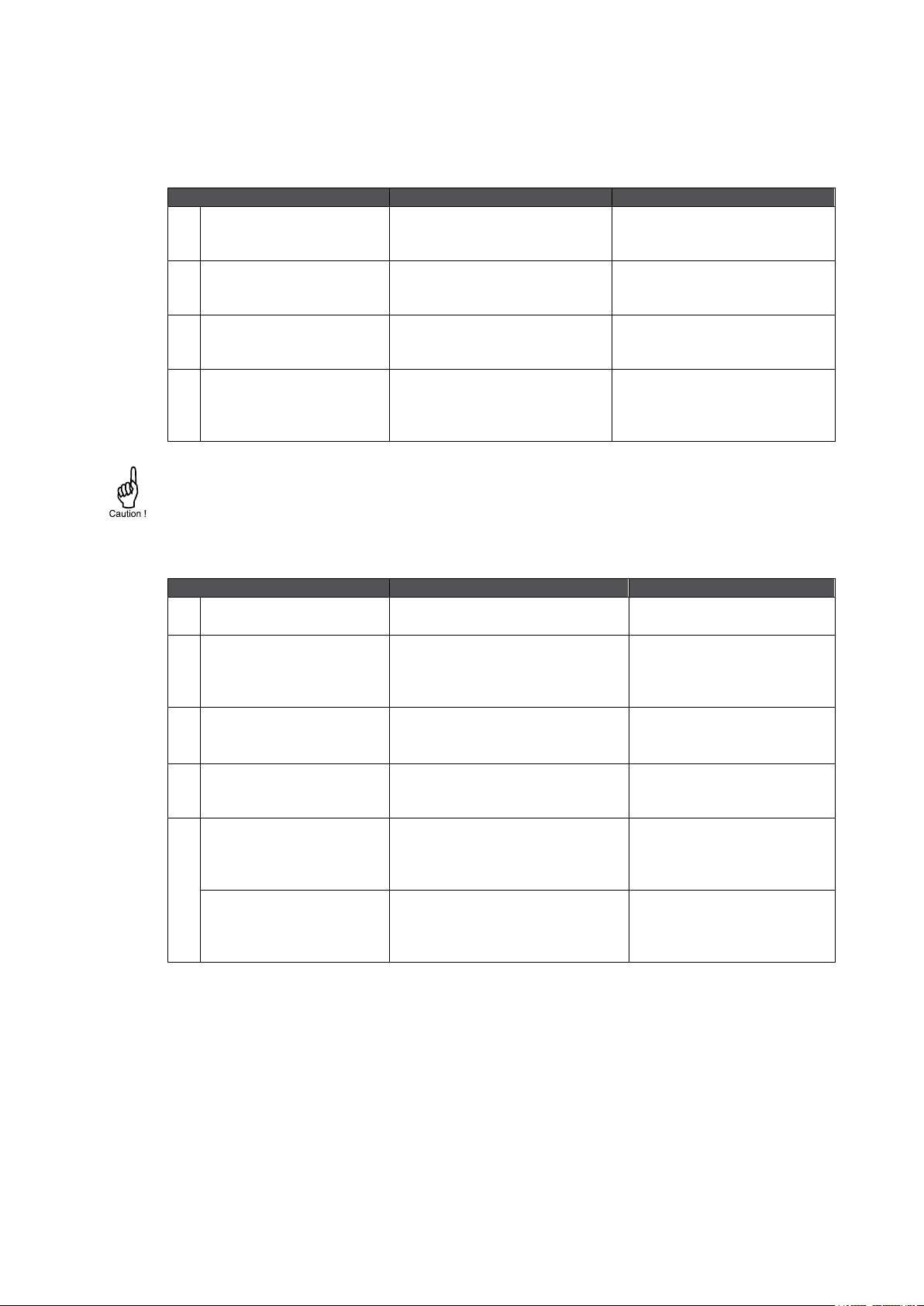
Action
Result
Remark
1
Press the SELECT/▲
key to select the first
setting.
The setting UNIT shows.
-
2
Press the SELECT/▲
key again to go to the
next setting.
The setting DECIMALS
shows.
-
3
Press the CLEAR/► key
to select the previous
setting.
The setting UNIT shows.
-
4
Press the CLEAR/►key
again to go to the
previous setting.
The submenu TOTAL
shows
This is normal behavior
because the setting UNIT is
the first setting of the
submenu TOTAL.
Changes are only saved when you press the PROG/ENTER key.
Action
Result
Remark
1
Momentarily, press the
PROG/ENTER key.
The PROG indicator blinks.
The engineering unit L shows.
To access the setting.
2
Press the SELECT/▲ key
to select the next
engineering unit.
The PROG indicator blinks.
The engineering unit m3 shows.
If you wait too long, the
program mode goes off and
changes are not saved, this
is normal behavior.
3
Press the SELECT/▲ key
to select the next
engineering unit.
The PROG indicator blinks.
The engineering unit US GAL
shows.
-
4
Press the CLEAR/► key
to select the previous
engineering unit
The PROG indicator blinks.
The engineering unit m3 shows.
-
5
To confirm the changes:
Momentarily, press the
PROG/ENTER key.
The PROG indicator goes off.
The change is saved.
The engineering unit m3 shows.
If you do not press the
PROG/ENTER key to
confirm, your selection is not
saved.
To discard the changes:
Press and hold the
PROG/ENTER key for
approximately 3 seconds.
The PROG indicator goes off.
The change is discarded.
The engineering unit L shows.
-
The SELECT/▲ key and the CLEAR/► key are used for navigation.
The explanation assumes that you are in the submenu TOTAL. When you are:
in the first setting and you navigate to the previous setting, the F112-A goes back to the related
main menu.
in the last setting and you navigate to the next setting, the F112-A goes to the related main
menu.
How to make a setting
The explanation assumes that you are in the submenu TOTAL and the setting UNIT. When you do
not want to save the change, wait for approximately 20 seconds or press and hold the
PROG/ENTER key for approximately 3 seconds.
FW_F112A_v1702_02_EN
Page 10

Page 10
1
TOTAL
11
unit
L; m3; kg; lb; GAL; USGAL; bbl; no unit
12
decimals
0000000; 111111.1; 22222.22; 3333.333
13
span
0.000001 - 999,999
14
decs span
0 - 6
2
FLOWRATE
21
unit
mL; L; m3; mg; g; kg; ton; gal; bbl; lb; cf; rev; - - - - (no unit);
scf; nm3; nL; p
22
time
/sec; /min; /hour; /day
23
decimals
0000000; 111111.1; 22222.22; 3333.333
24
span
0.000001 - 999,999
25
decs span
0 - 6
3
DISPLAY
31
function
total; rate
32
light
0% (off); 20%; 40%; 60%;- 80%; 100% (full brightness)
4
POWER MANAGEMENT
41
LCD new
fast; 1 sec; 3 sec; 15 sec; 30 sec; off
42
battmode
operational; shelf
5
FLOWMETER
51
formula
interpolation; square root
52
filter
01 - 99
53
cut-off
0.0 - 99.9%
54
calib-lo
default; calibrate; calibrate set
55
calib-hi
default; calibrate; calibrate set
6
LINEARIZATION
61
% / M-FACTOR 1
0.01% – 99.99% / 0 – 9.999999
62
% / M-FACTOR 2
0.01% – 99.99% / 0 – 9.999999
6F
% / M-FACTOR 15
0.01% – 99.99% / 0 – 9.999999
6G
linearization
enable; disable
7
ANALOG
71
output
disable; enable
72
rate-min
000.000 - 999999
73
rate-max
000.000 - 999999
74
cut-off
0.0 - 9.9%
75
tune-min
0 - 9999
76
tune-max
0 - 9999
77
filter
01 - 99
8
PULSE
81
width
0.001 - 9.999
82
decimals
0000000; 111111.1; 22222.22; 3333.333
83
amount
0.001 - 9999999
9
COMMUNICATION
91
speed
1200; 2400; 4800; 9600; 9600HP; 19200; 38400
92
address
1 – 247
93
mode
bus-rtu; bus-asc; off
94
databits
8 bits; 7 bits
95
parity
none; even; odd
A
OTHERS
A1
model
F112-A
A2
software version
nn:nn:nn
A3
serial no.
nnnnnnn
A4
password
0000 - 9999
A5
tag-nr
0000000 - 9999999
3.1.1. SETUP MENU - SETTINGS
FW_F112A_v1702_02_EN
Page 11
Page 11
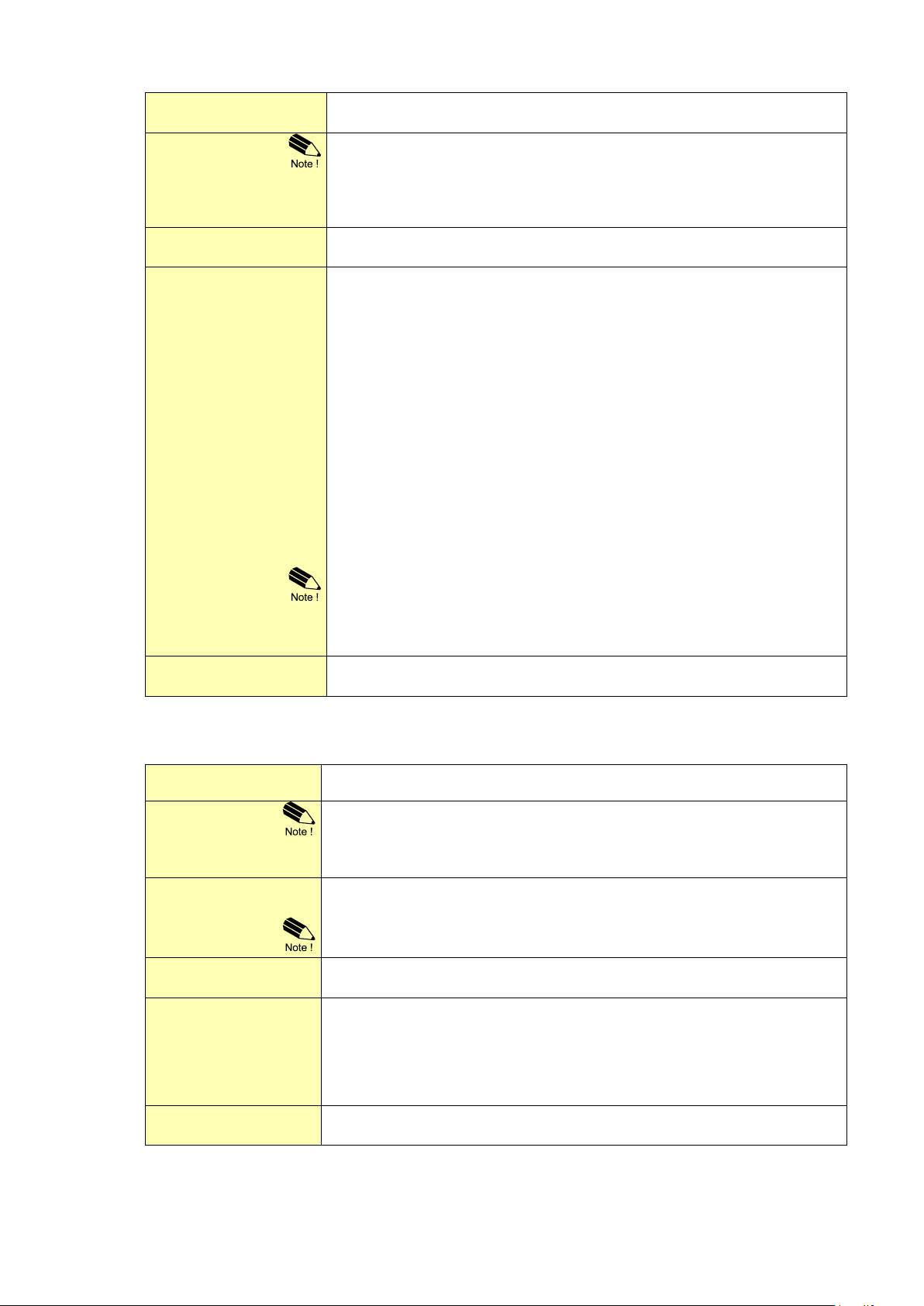
UNIT
11
This setting is used to select the engineering unit for the indication of the total, the
accumulated total and the pulse output.
When you change the engineering unit , you must recalculate and reprogram the
span for the (accumulated) total. When you recalculate and reprogram the span, the
history for (accumulated) total is not correct anymore, because the (accumulated)
total is not recalculated. For future reference, best practice is to make a note of the
accumulated total before you program the recalculated span.
DECIMALS
12
This setting is used to set the amount of digits behind the decimal point for the
(accumulated) total indication.
SPAN
13
This setting is used to set the span for the total. With the span, the
flowmeter signal is converted to a quantity. The span for Total is based on
the engineering unit (SETUP 11) and the flow rate per second at 20mA
(or max signal). Enter the span with the decimals (decimals are not shown
yet and are set in SETUP 14). The more accurate the span, the more
accurate the functioning of the system will be.
0BExample 1: Calculating the Span.
Assume that the flowmeter generates 20mA at a rate of 652.31 USGAL per hour,
the selected unit is barrels. There are 42 gallons in one barrel; so the rate is
652.31/42 is 15.53119 barrels/hour. This is 0.0043142 barrels/second, which is
the span. Enter for the span: "004314" and for the span decimals "6".
0BExample 2: Calculating the Span.
Assume that the flowmeter generates 20mA at a flow rate of 2,481.3 Liters/minute
and the selected unit is "m3". The rate per second is 2,481.3÷60 is 41.355 L/sec.
This is 0.041355 m3/sec., which is the span.
Enter for the span: "041355" and for the span decimals "6".
When you recalculate and enter a new span, the history for
(accumulated) total is not correct anymore, because the
(accumulated) total is not recalculated. for future reference. Best
practice is to make a note of the accumulated total before you enter
the recalculated span.
DECS SPAN
14
This setting is used to set the amount of digits behind the decimal point for the
span.
UNIT
21
This setting is used to select the engineering unit for the indication of the flow rate.
Alteration of the engineering unit will have consequences for
operator and setup values, they will not be automatically recalculated
to the value of the new selected unit. The span has to be adapted as
well; the calculation is not done automatically.
TIME
22
This setting is used to set the time unit for the flow rate calculation. Note that the
flow rate is given in engineering unit/time unit, e.g. liters/minute (l/min).
When you change this setting, also recalculate and change the settings for
the analog rate-min and analog rate-max.
DECIMALS
23
This setting is used to set the amount of digits behind the decimal point for the flow
rate indication.
SPAN
24
This setting is used to set the span for the total. With the span, the
flowmeter signal is converted to a quantity. The span for Total is based on
the engineering unit (SETUP 21) and the flow rate per second at 20mA (or
max signal). Enter the span with the decimals (decimals are not shown yet
and are set in SETUP 25). The more accurate the span, the more accurate
the functioning of the system will be.
DECS SPAN
25
This setting is used to set the amount of digits behind the decimal point for the
span.
3.1.2. EXPLANATION OF SETUP-MENU 1 - TOTAL
3.1.3. EXPLANATION OF SETUP-MENU 2 - FLOW RATE
The settings for total and flow rate are entirely separate. In this way, different engineering units can
be used for each e.g. cubic meters for total and liters for flow rate.
FW_F112A_v1702_02_EN
Page 12
Page 12
FUNCTION
31
This setting can be set to display (linearized) total or (linearized) rate.
When 'total' is selected, simultaneously, total is shown with the large
digits and flow rate with the smaller digits. When SELECT is pressed,
the accumulated total is shown temporarily.
When 'rate' is selected, only flow rate will be shown with the large
digits together with its measuring unit. When SELECT is pressed, the
total and the accumulated total are shown temporarily.
LIGHT
32
The backlight brightness can be adjusted from 0% (off) to 100% (full
brightness) in steps of 20%.
When the F112-A is only loop powered, the backlight is disabled. An
external power supply is required to supply the backlight.
LCD NEW
41
The calculation of the display-information influences the power
consumption significantly. When the application does not require a fast
display refresh rate, it is strongly advised to select a slow refresh rate.
Please understand that NO information will be lost; every pulse will be
counted and the output signals will be generated in the normal way.
At a key press, the display refresh rate will switch to FAST for 30
seconds. When 'OFF' is selected, the display goes off after 30 seconds
after the last key press. The display temporarily comes on after a key
press.
Example battery life-time with a coil pick-up:
FAST update: about 2 years;
1 sec update: about 5 years.
BATTERY MODE
42
The F112-A has two modes: operational or shelf.
After "shelf" has been selected, the F112-A can be stored for several years; it will
not process the sensor signal; the display is switched off but all settings and totals
are stored. In this mode, power consumption is extremely low.
To wake up the F112-A again, press the SELECT/ key two times.
FORMULA
51
The F112-A can process the (0)4-20mA signal in two ways:
Interpolation or Square root:
Interpolation: the signal is processed linear: R = S x I
Square root: for differential pressure: R = S √ I
where:
R = Rate: the calculated flow rate
S = Span: the maximum flow rate at 20mA. The span is programmed with
setting 24 for flow rate and with setting 13 for total.
I = Input: the scaled analog value; in these formulas value 0 (zero) for
(0)4mA and value 1 (one) for 20mA.
FILTER
52
The analog output signal of a sensor represents the actual temperature.
This signal is measured several times a second. The value measured is a
"snap-shot" of the real temperature as it will be fluctuating.
With the help of this digital filter a stable and accurate reading can be
obtained while the filter level can be set to a desired value.
The filter principal is based on three input values: the filter level (01-99),
the last measured analog value and the last average value. The higher
the filter level, the longer the response time on a value change will be.
CUT-OFF
53
To ignore e.g. leakage of the flow or vibration, a low-flow cut-off can be
set as percentage over the full range of 16mA (or 20mA / 10V). When the
analog value is less than the programmed percentage, with this setting,
the flow rate will be set to zero. The cut-off value can be programmed is
the range 0.0 - 99.9%.
3.1.4. EXPLANATION OF SETUP-MENU 3 - DISPLAY
3.1.5. EXPLANATION OF SETUP-MENU 4 - POWER MANAGEMENT
When used with the internal battery option (type PB/PC), the user can expect reliable measurement
over a long period of time. The F112-A has several smart power management functions to extend
the battery life time significantly. Two of these functions can be set.
3.1.6. EXPLANATION OF SETUP-MENU 5 - FLOWMETER
EXAMPLE:
FW_F112A_v1702_02_EN
Page 13
Page 13
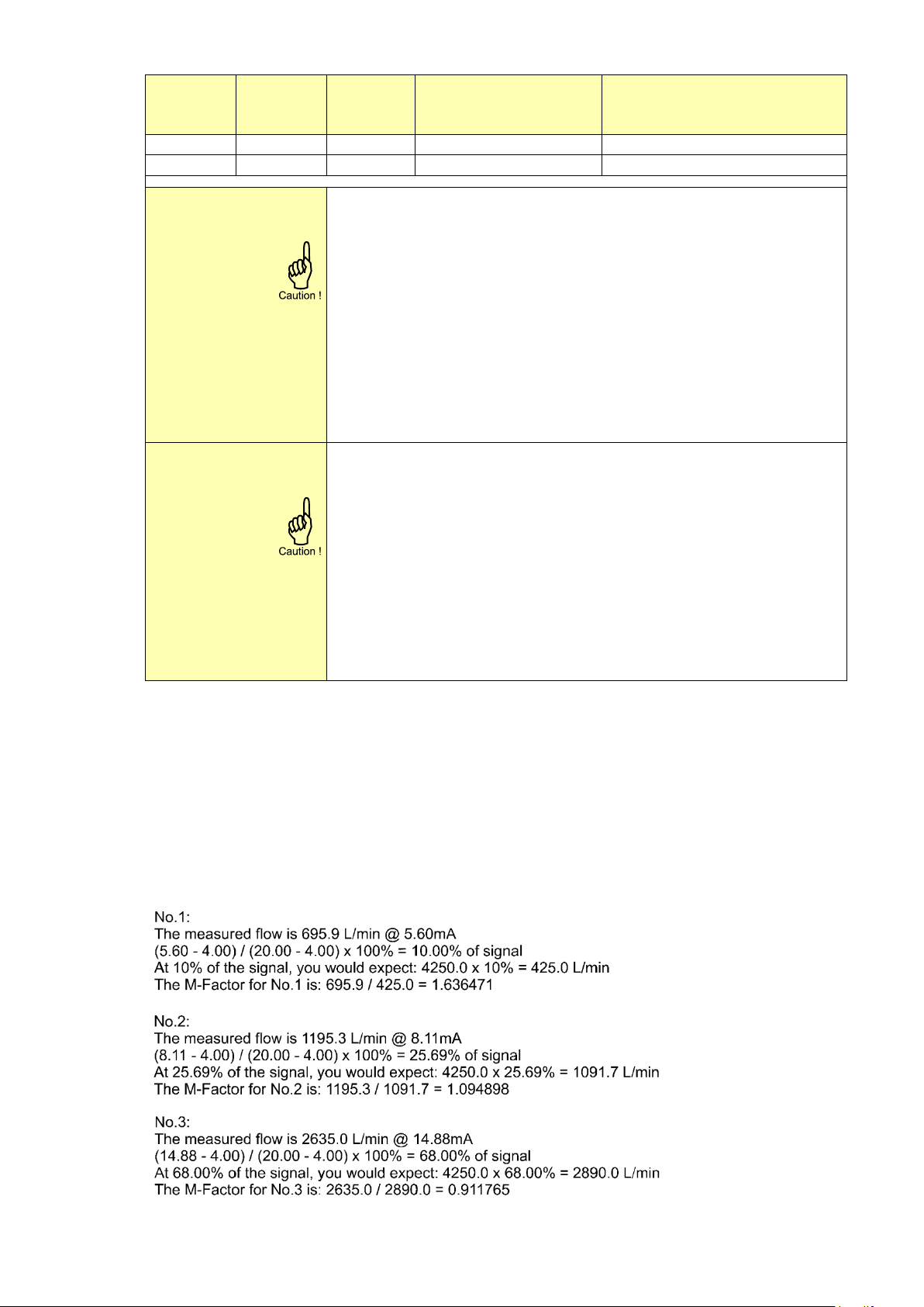
FUNCTION
(SETUP
51)
SPAN
(SETUP
13/24)
REQUIRED
CUT-OFF
CUT-OFF
(SETUP 53)
REQUIRED OUTPUT
interpolation
450 L/min
25 L/min
25/450 x 100%=5.5%
16mA x 5.5% + 4mA = 4.88mA
square root
450 L/min
25 L/min
(25/450)2 x 100%=0.3%
16mA x 0.3% + 4mA = 4.05mA
CALIB-LO
54
This setting is used to calibrate the input value for (0)4mA as the signal
from the flowmeter might not be exact 4.0 mA (or 0.0 mA) at flow rate
zero. This function will measure the real output value at flow zero.
Be very sure that the offered signal is correct before the calibration
is executed as this function has major influences on the accuracy of
the system!
After pressing PROG, three settings can be selected:
CALIB: with this setting, the input will be calibrated with the actual
"(0)4mA" value. After pressing enter, CAL SET will be shown as soon
as the calibration is completed. From that moment, the analog value
must be more than the calibrated value before the signal will be
processed.
DEFAULT: with this setting, the manufactures value is re-installed.
CAL SET: to select the last calibrated value.
CALIB-HI
55
This setting is used to calibrate the input value for 20mA as the signal
from the flowmeter might not be exact 20.0 mA at maximum flow rate.
This function will measure the real output value at maximum flow rate.
Be very sure that the offered signal is correct before the calibration
is executed as this function has major influences on the accuracy of
the system!
After pressing PROG, three settings can be selected:
CALIB: with this setting, the input will be calibrated with the actual
"20mA" value. After pressing enter, CAL SET will be shown as soon
as the calibration is completed. From that moment, the analog value
must be less than the calibrated value for a reliable measurement.
DEFAULT: with this setting, the manufactures value is re-installed.
CAL SET: to select the last calibrated value.
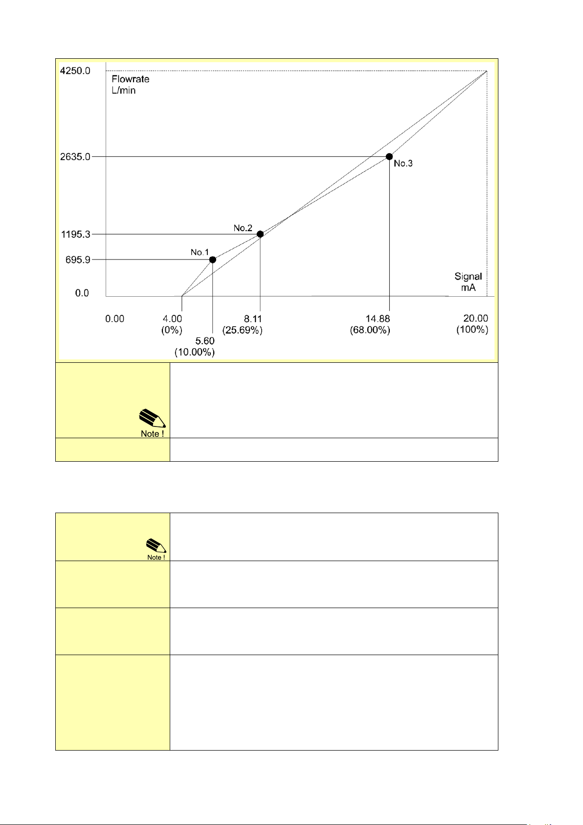
3.1.7. EXPLANATION OF SETUP MENU 6 - LINEARIZE
The linearization function is available to approach the real flow curve better as with the general
K-Factor (KF0). This to obtain a more accurate flow rate, total and accumulated total as well as the
analog and pulse output at any flowmeter frequency. A maximum of 15 linearization-positions can be
entered while the interpolation will calculate any other position in-between.
For each linearization position, the percentage of the signal and a Meter Factor (MF) must be
entered. The lowest percentage and MF you enter will be valid from (0)4mA. The highest percentage
and MF will be valid till 20mA. It is advised to enter the percentages in increasing order, however it is
not necessary.
Please have a look at following example to understand the calculation and the method of
linearization:
FW_F112A_v1702_02_EN
Page 14
Page 14
FREQUENCY /
M-FACTOR
61 TO 6F
The percentage is shown at the bottom line of the display.
With value 0%, the M-Factor is disabled. The M-Factor (MF) is shown at the
top-line of the display. The minimum value to be entered is 0.000001 and the
maximum value is 9.999999.
The MF is mostly a figure around 1.000000, like 0.945354 or 1.132573 and
always has six decimals, but the decimal separator is not shown.
LINEARIZE
6G
This setting is used to enable or disable the linearization function.
OUTPUT
71
If the analog output is not used, select disable to minimize the power
consumption (e.g. save battery life-time).
Option AP: When a power supply is available but the output is disabled, a
3.5mA signal will be generated.
RATE-MIN
72
Enter here the flow rate at which the output should generate the minimum
signal (0)4mA or 0V - in most applications at zero flow. The number of
decimals shown depend upon setup 23. The engineering units/time (e.g.
L/min) are dependent upon setup 21 and 22.
RATE-MAX
73
Enter here the flow rate at which the output should generate the maximum
signal (20mA or 10V) - in most applications at maximum flow. The number
of decimals shown depend upon setup 23. The engineering units/time
(e.g. L/min) are dependent upon setup 21 and 22.
CUT-OFF
74
To ignore leakage of the flow for example, a low flow cut-off can be set as
a percentage of the full range of 16mA, 20mA or 10V.
When the flow is less than the required rate, the current will be the
minimum signal (0)4mA or 0V.
Example: Calculate the cut-off.
Rate-min: 0L/min [4mA], Rate-max: 100 L/min [16mA], Cut-off: 2%
Required rate [L/min]: (rate-max - rate-min)*cut-off: (100-0)*2%=2.0L/min
Output [mA]: rate-min + (rate-max*cut-off): 4+(16*2%)=4.32mA
3.1.8. EXPLANATION OF SETUP MENU 7 - ANALOG
A linear 4-20mA signal (option AB: 0-20mA or option AU: 0-10V) output signal is generated that represents the flow rate.
The settings for the flow rate influence the analog output directly. The relationship between the flow
rate and the analog output is set with the following settings.
FW_F112A_v1702_02_EN
Page 15
Page 15
TUNE-MIN
75
The (0)4mA or 0V value can be tuned precisely with this setting. The
initial minimum analog output value is (0)4mA or 0V. However, this value
might differ slightly due to ambient influences such as temperature for
example.
Before tuning the signal, be sure that the analog signal is not being
used for any application!
After pressing PROG, the current will be about 4mA (0mA or 0V). The
current can be increased / decreased with the arrow keys and is directly
active. Press ENTER to store the new value.
If required, you can program the analog output 'up-side-down'. The
(0)4mA or 0V represents the maximum flow rate and the 20mA or 10V
represents the minimum flow rate.
TUNE-MAX
76
The 20mA or 10V value can be tuned precisely with this setting. The initial
maximum analog output value is 20mA or 10V However, this value might
differ slightly due to ambient influences such as temperature for example.
Before tuning the signal, be sure that the analog signal is not being
used for any application!
After pressing PROG, the current will be about 20mA or 10V. The current
can be increased / decreased with the arrow keys and is directly active.
Press ENTER to store the new value.
If required, you can program the analog output 'up-side-down'. The
(0)4mA or 0V represents the maximum flow rate and the 20mA or 10V
represents the minimum flow rate.
FILTER
77
This setting is used to stabilize the output signal. With the help of this
digital filter a more stable but less actual representation of the flow rate
can be obtained.
The filter principal is based on three input values: the filter level (01-99),
the last calculated flow rate and the last average value. The higher the
filter level, the longer the response time on a value change will be.
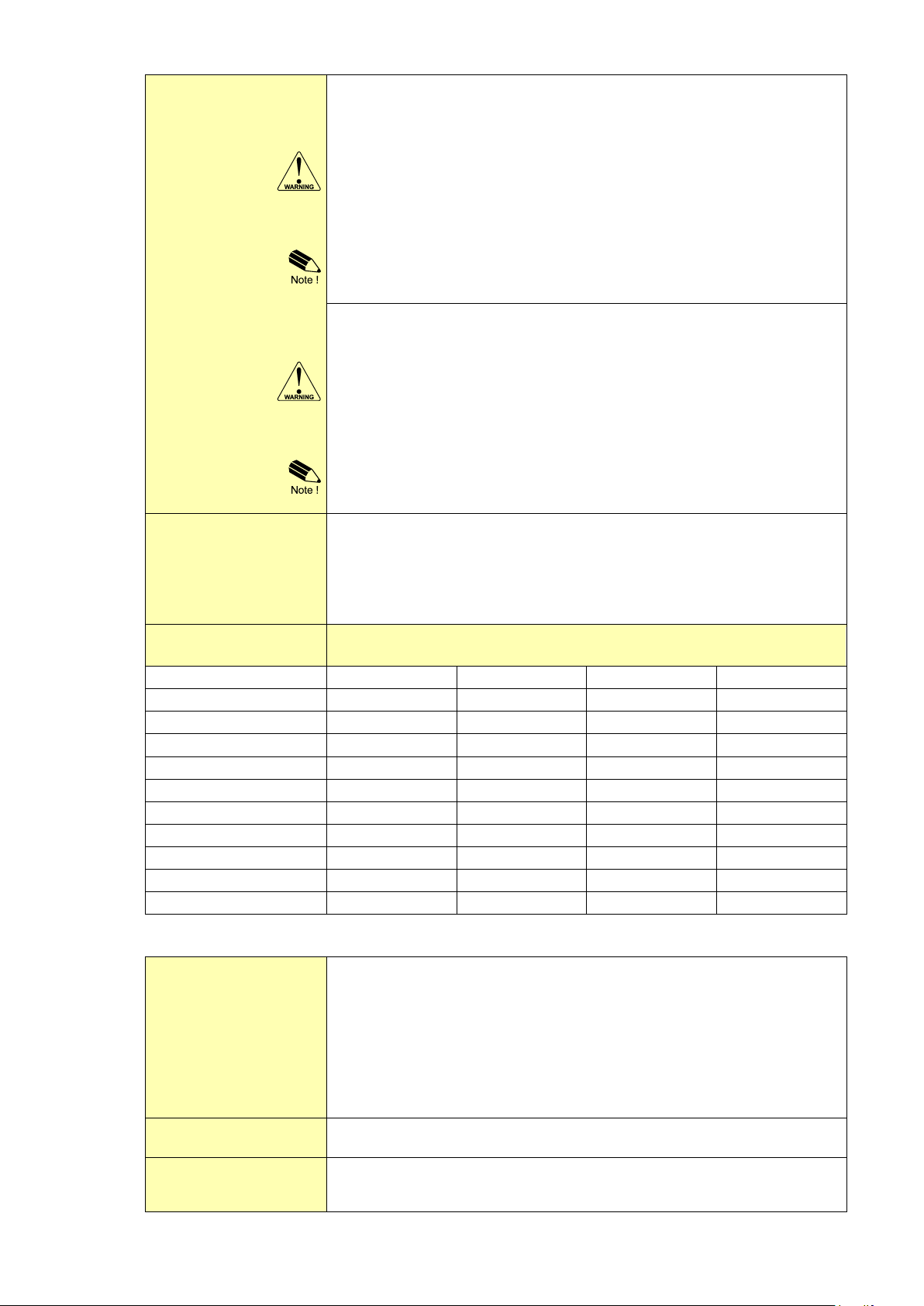
FILTER VALUE
RESPONSE TIME ON STEP CHANGE OF ANALOG VALUE.
TIME IN SECONDS
INFLUENCE
50%
75%
90%
99%
01
filter disabled
filter disabled
filter disabled
filter disabled
02
0.1 sec
0.2 sec
0.4 sec
0.7 sec
03
0.2 sec
0.4 sec
0.6 sec
1.2 sec
05
0.4 sec
0.7 sec
1.1 sec
2.1 sec
10
0.7 sec
1.4 sec
2.2 sec
4.4 sec
20
1.4 sec
2.8 sec
4.5 sec
9.0 sec
30
2.1 sec
4 sec
7 sec
14 sec
50
3.5 sec
7 sec
11 sec
23 sec
75
5.2 sec
10 sec
17 sec
34 sec
99
6.9 sec
14 sec
23 sec
45 sec
WIDTH
81
The pulse width determines the time that the output will be active; in other
words the pulse duration. Value “zero” will disable the pulse output.
The pulse signal always has a 50% duty cycle, hence the minimum time
between the pulses is equal to the pulse width setting. If the frequency
should go out of range – when the flow rate increases for example – an
internal buffer will be used to “store the missed pulses”: As soon as the
flow rate slows down, the buffer will be “emptied”.
It might be that pulses will be missed due to a buffer-overflow, so it is
advised to program this setting within its range!
DECIMALS
82
This setting is used to set the amount of digits behind the decimal point for the
amount.
AMOUNT
83
A pulse will be generated every time a certain quantity is added to the
total. Enter this quantity here while taking the decimals for pulse into
account.
3.1.9 EXPLANATION OF SETUP MENU 8 - PULSE
One transistor or mechanic relay output is available as a scaled pulse output according to the total.
FW_F112A_v1702_02_EN
Page 16
Page 16
SPEED
91
This setting is used to set the Baudrate.
9600 is a low power setting, 9600HP is a high power setting (Modbus compliant).
ADDRESS
92
This setting is used to set the communication address for the F112-A.
MODE
93
This setting is used to set the Modbus transmission mode. Select OFF to disable
the communication.
DATABITS
94
This setting determines for communication the number of data bits.
Select 8 bit for BUS-RTU and 7 bits for BUS-ASC.
PARITY
95
As demanded by the connected equipment, select a parity bit (odd, even or none).
MODEL
A1
This setting shows the model name.
SOFTWARE VERSION
92
This setting shows the version number of the firmware (software).
SERIAL NO
A3
This setting shows the serial number.
PASSWORD
A4
This setting is used to set a password (pin code) to limit the access for the
setup menu. Only persons who know the pin code can access the setup
menu. The pin code 0000 disables the pin code to allow for access by any
person.
TAG-NR
A5
This setting is used to set a tag number for the F112-A .
3.1.10. EXPLANATION OF SETUP-MENU 9 - COMMUNICATION (OPTION)
This product is designed for the connection to a communication network. Products with a
communication option do not include cyber security functions. Fluidwell cannot take any
responsibility for the cyber security, omissions or errors in the communication safety. To maintain a
secure operation, automation and control, it is the sole responsibility of the owner to install and
manage the appropriate safety measures to protect the network, the product and the communication
against any kind of security breaches.
The functions described below deal with hardware that is not part of the standard delivery.
Programming of these functions does not have any effect if this hardware has not been installed.
Consult Appendix C and the Modbus communication protocol description for a detailed explanation.
3.1.11. EXPLANATION OF SETUP-MENU A - OTHERS
For support and maintenance it is important to have information about the characteristics of the F112-A. Your
supplier will ask for this information when support is required.
FW_F112A_v1702_02_EN
Page 17
Page 17
Mounting, electrical installation, start-up and maintenance of this device may only be
carried out by trained persons authorized by the operator of the facility. Persons must
read and understand this manual before carrying out its instructions.
This device may only be operated by persons who are authorized and trained by the
operator of the facility. All instructions in this manual are to be observed.
Make sure, the measuring system is correctly wired up according to the wiring diagrams.
Protection against accidental contact is no longer assured when the housing cover is
removed or the panel cabinet has been opened (danger from electrical shock). The
housing may only be opened by trained persons authorized by the operator of the facility.
Take careful notice of the "Safety rules, instructions and precautionary measures" at the
front of this manual.
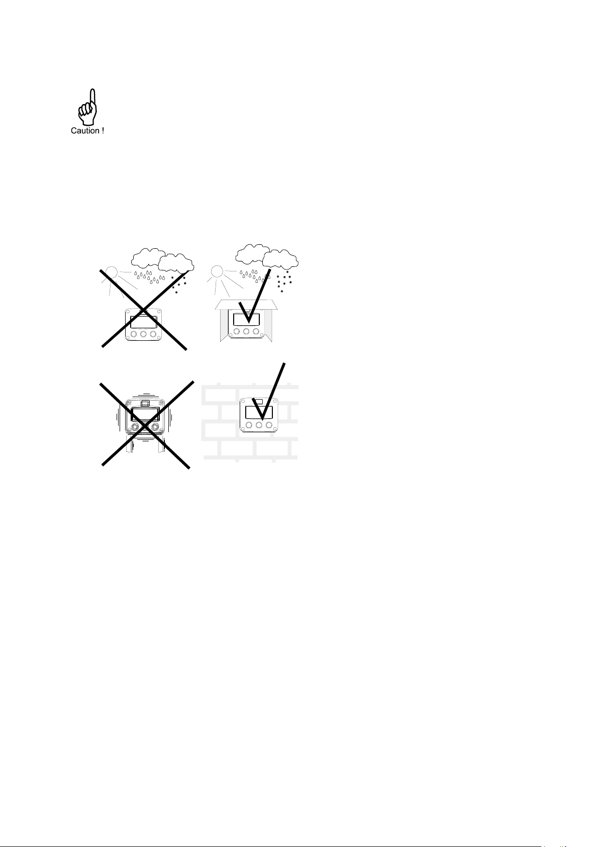
Take the relevant IP classification of the
enclosure into account (see identification plate).
Even an enclosure rated for IP67 / TYPE 4(X)
should NEVER be exposed to strongly varying
(weather) conditions.
When panel-mounted, the front panel of the
F112-P is rated for IP65 / TYPE 4(X)!
When used in very cold surroundings or varying
climatic conditions, inside the instrument case,
take the necessary precautions against moisture.
Mount the F112-P onto a solid structure to avoid
vibrations.
4. INSTALLATION
4.1. General directions
4.2. INSTALLATION / SURROUNDING CONDITIONS
FW_F112A_v1702_02_EN
Page 18
Page 18
75 mm (2.95")
130 mm (5.12")
112 mm (4.40")
1
2
0
m
m
(
4
.
7
2
”
)
M20 x 1,5
PG9
PG9
30mm 30mm
M20 x 1,5
M16 x 1,5 M16 x 1,5
30mm 30mm
M20 x 1,5
M20 x 1,5 M20 x 1,5
25mm 25mm
1/2"NPT
0
.
9
”
3x 1/2"NPT
0.12" 0.12"
HA
HM
HN
HO
HP
HT
HU
6 x M12
12mm
12mm
24mm 24mm
36mm
36mm
1
4
m
m
1
7
m
m
115 mm (4.53”)
HB
29.1 mm (1.15”)
31 mm
(1.22”)
HZ
4x M20 x 1,5
15 15
HV
23 23
1
6
mm
1/2"NPT 1/2"NPT
25mm 25mm
2
2
,
5
m
m
HL
2
2
,
5
m
m
2
2
,
5
m
m
2
2
,
5
m
m
2
2
,
5
m
m
0
.
9
”
1
5
6
0
m
m
(
2
.
3
6
”
)
9
8
m
m
(
3
.
8
6
”
)
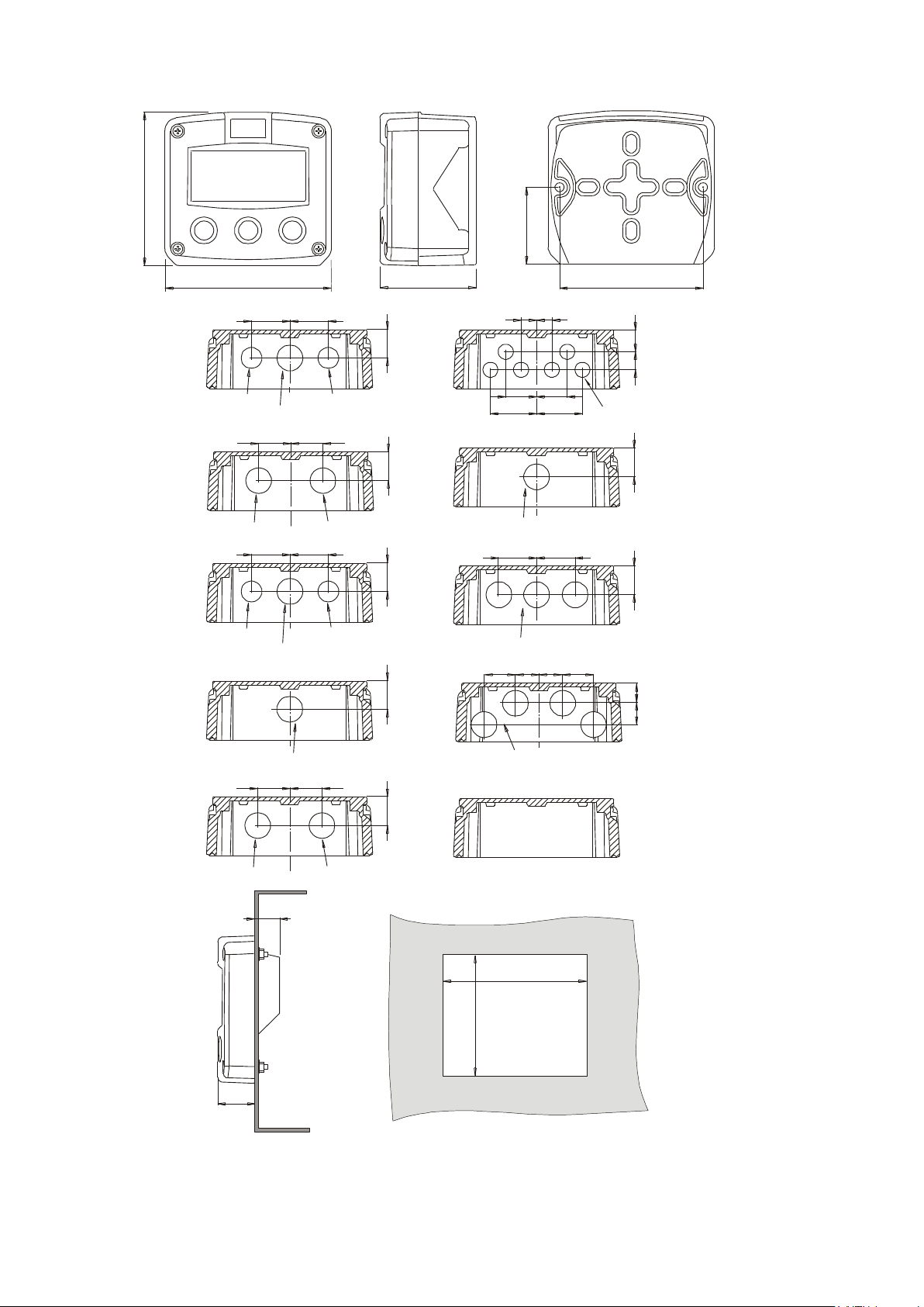
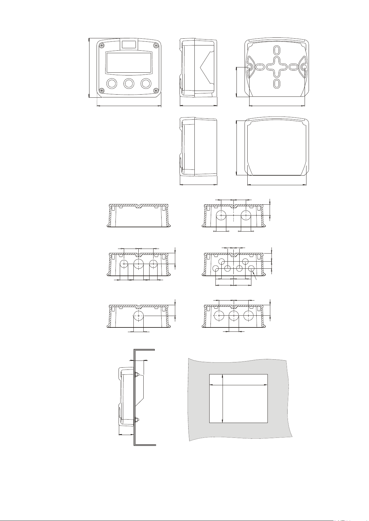
4.3. DIMENSIONS- ENCLOSURE
Fig. 5: Aluminum enclosures - Dimensions
FW_F112A_v1702_02_EN
Page 19
Page 19
75 mm (2.95")
130 mm (5.12")
112 mm (4.40")
60 mm (2.36")
120 mm (4.72")
HD
HK
HK back box:
(flat bottom)
HE
HF
HG
HH
D=12mm
12mm
12mm
24mm24mm
36mm
36mm
14mm
17mm
22,5mm
30mm 30mm
D=16mm
D=20mm
0.9"
D=22mm (0.866")
22,5mm
25mm 25mm
D=20mm D=20mm
D=16mm
HC
75 mm (2.95")
118 mm (4.65”)
104 mm (4.09”)
HJ
0.9”
0.12” 0.12”
3x D=22mm (0.866”)
115 mm (4.53”)
98 mm (3.86”)
29.1 mm (1.15”)
31 mm
(1.22”)
Fig. 6: GRP enclosures - Dimensions
FW_F112A_v1702_02_EN
Page 20
Page 20
Electro static discharge does inflict irreparable damage to electronics! Before installing or
opening the F112-P, the installer has to discharge himself by touching a well-grounded
object.
Do ground the aluminum enclosure properly as indicated. It is the responsibility of the
installer to install, connect and test the Protective Earth connections in accordance with
the (inter)national Rules and Regulations.
This chapter shows general information regarding the electrical installation of the F112-P.
Chapter 5 gives additional specific information regarding Intrinsically safe installation and
overrules the information given in this chapter.
When installed in an aluminum enclosure and a potentially explosive atmosphere
requiring apparatus of equipment protection level Ga and Da, the unit must be installed
such that, even in the event of rare incidents, an ignition source due to impact or friction
sparks between the enclosure and iron/steel is excluded.
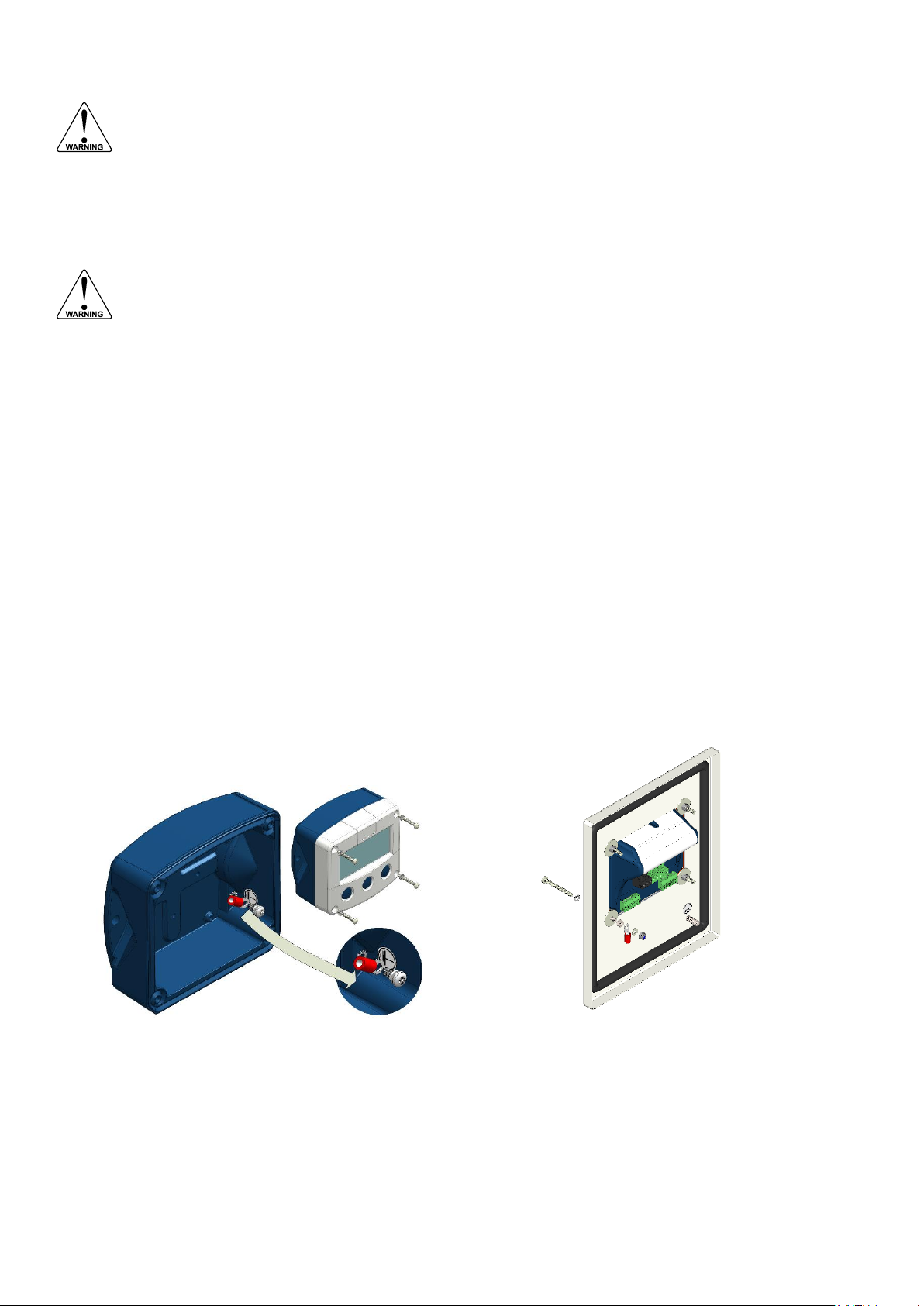
Field mounted
Panel mounted
4.4. INSTALLING THE HARDWARE
4.4.1. GENERAL INSTALLATION GUIDELINES
In the F112-P, different types of bonding and earthing are used. The common (ground) is mostly
used for termination of the wire shields and the Protective Earth (PE) is used for electrical safety.
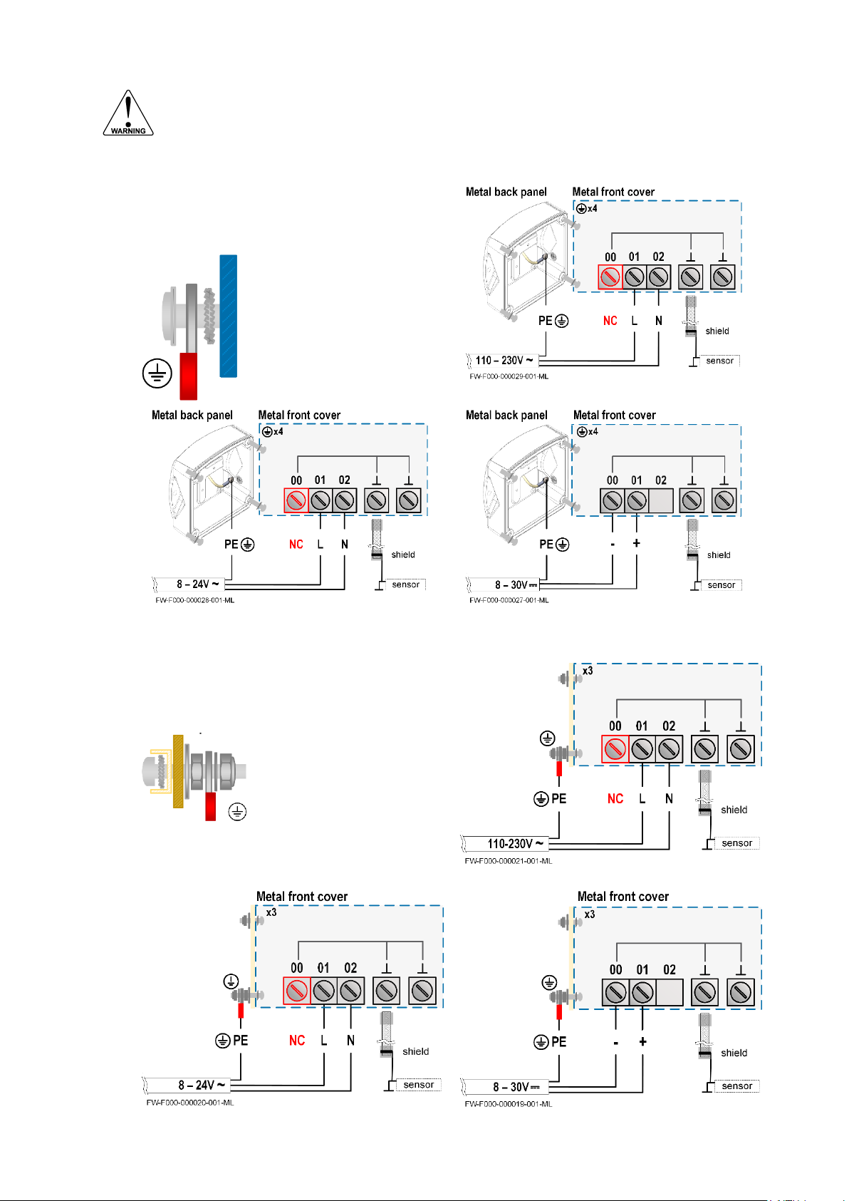
The F112-P that came with a power module type PM; 110V-230V AC or type PD/PF with an
option OR (the relays can handle 110V-230V AC) shall be connected to the Protective Earth (PE)
stud which is installed in the metal back panel. The metal front panel is connected to the
Protective Earth by the mounting screws and serrated washers.
For V AC applications, the terminal 00 shall not be connected to avoid earth loops.
For V DC applications, the terminal 00 shall be connected to the common (do NOT use for PE).
The wire screens (shield) are meant to prevent electromagnetic interference and shall be,
galvanic isolated, connected to the common ground terminals that belong to the specific sensor
connection. The wire screens shall be terminated at one side to prevent wire loops. Inside of the
Fluidwell unit, the different common ground terminals are connected to each other. It is advised,
as illustrated, to terminate the wire screens in the vicinity of the sensor and to insulated the wire
screen with a shrink tube at the Fluidwell unit side.
Separate cable glands with effective IP67 / TYPE 4(X) seals for all wires.
Unused cable entries: ensure that you fit IP67 / TYPE 4(X) plugs to maintain rating.
A reliable ground connection for both the sensor, and if applicable, for the metal enclosure
(above).
An effective screened cable for the input signal, and grounding of its screen to the “┴ “ terminal or
at the sensor itself, whichever is appropriate to the application.
FW_F112A_v1702_02_EN
Page 21
Page 21
Risk of damage to equipment!
Do not use the terminal 00 to connect the protective earth wire, the 00 and the common
ground terminals are internally connected. Be careful, to prevent damage to equipment when
you connect different power supplies (sensor, PLC, etc.). Inside the Fluidwell display, the
common grounds are internally connected to each other.
The PE connection
The PE connection is made with the PE stud
inside the back panel and the 4 mounting
screws that attach the cover to the back panel.
Type PM (110-230V AC)
The PE connection in the
metal back panel is made
with a serrated washer, a
terminal, a washer and a
screw.
The PE connection to the
metal cover is made with the
serrated washers and the
mounting screws.
Type OR (8-24V AC)
Type OR (8-30V DC)
The PE connection
The PE connection is made with one of the
mounting screws that attaches the front panel
to the panel.
Type PM (110-230V AC)
The PE connection to the
metal cover is made with the
serrated washers and the
mounting screws.
The PE connection to the
panel is made with the
washer, the nut, the
terminal, the washer and a
lock nut.
Type OR (8-24V AC)
Type OR (8-30V DC)
4.4.2. ALUMINUM ENCLOSURE - FIELD MOUNTED
4.4.3. ALUMINUM ENCLOSURE - PANEL MOUNTED
FW_F112A_v1702_02_EN
Page 22
Page 22
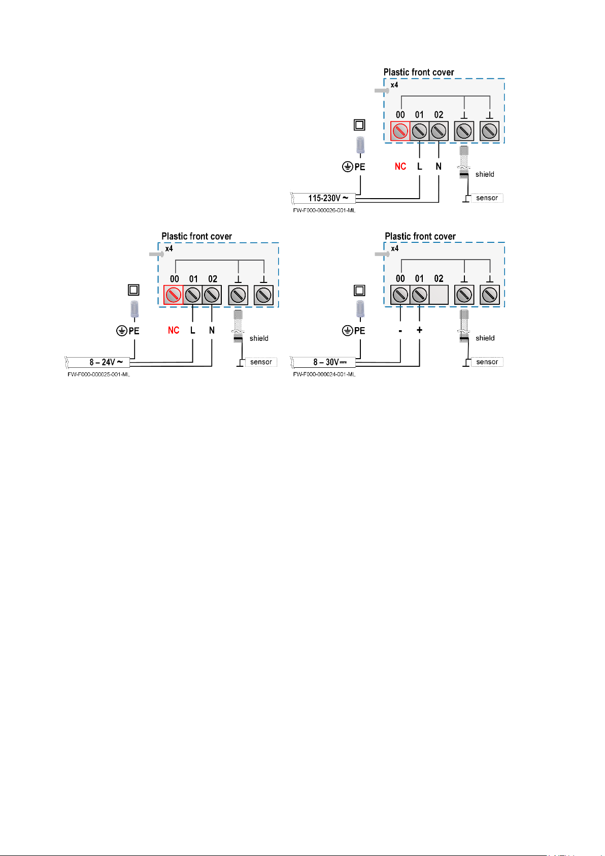
The PE connection
The F112-P in a GRP enclosure meets the
requirements of class 2 (double insulated).
Therefore the incoming PE wire is terminated
with an insulating end cap.
Type PM (110-230V AC)
Type OR (8-24V AC)
Type OR (8-30V DC)
4.4.4. PLASTIC (GRP) ENCLOSURE
FW_F112A_v1702_02_EN
Page 23
Page 23
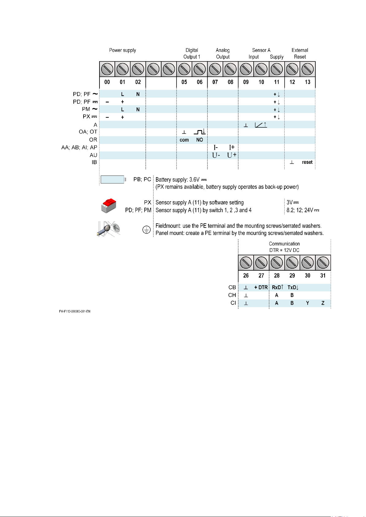
4.4.5. TERMINAL CONNECTORS
Refer to Appendix A: Technical Specification
Fig. 7: Overview of terminal connectors - Standard configuration and options
4.4.6. SENSOR SUPPLY
For type PB/PC; PX; AP: There is no real sensor supply out available. Only a limited power supply
is available. This power supply MAY NOT be used to supply the flowmeters electronics, converters
etc. as it will not provide adequate sustained power ! All energy used by the flowmeters pick-up will
directly influence the battery life-time. It is strongly advised to use a "zero power" pickup such as a
coil or reed-switch when operating without external power. It is possible to use some low power NPN
or PNP output signals, but the battery life time will be significantly reduced (consult your distributor).
The sensor supply is fixed: 1.2V DC or 3V DC (set by the firmware).
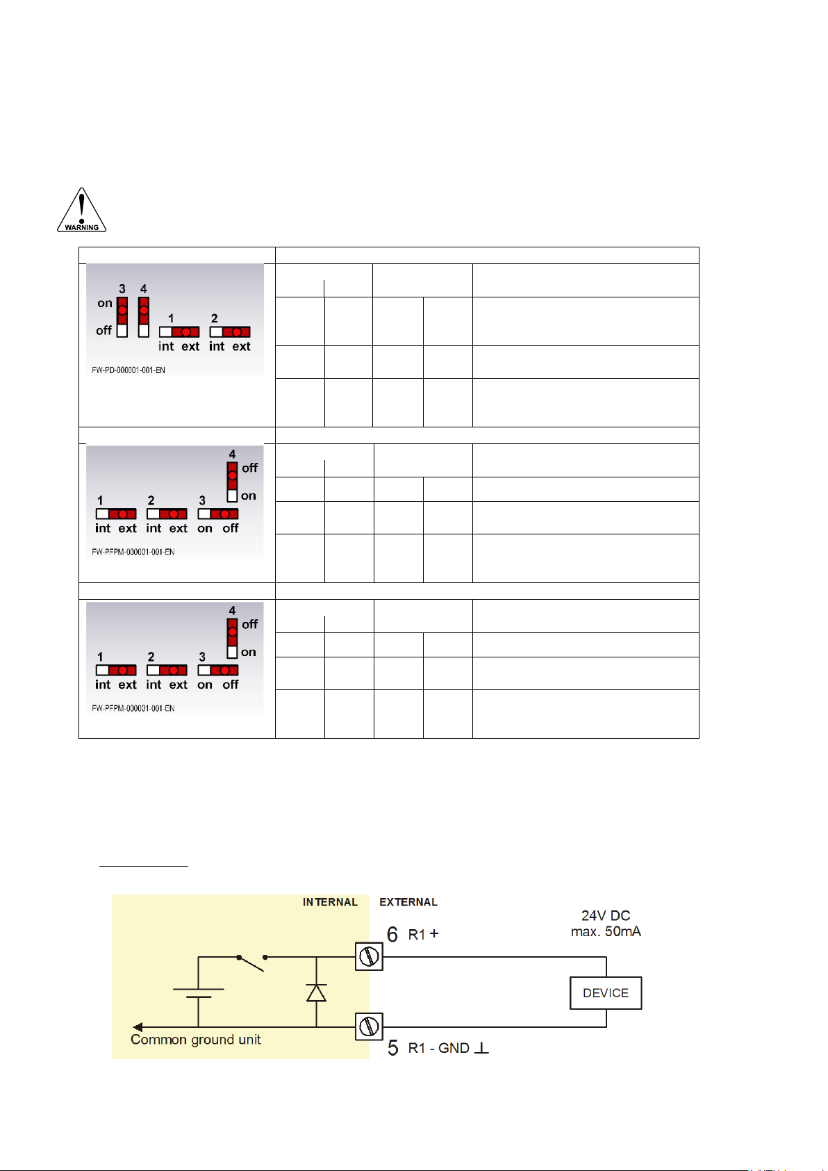
For type PD; PF; PM: It is possible to supply the sensor with different voltages. You can set the
voltage with the switches. Internal power is only applicable for low power sensors (Coil, Reed).
External power is only available when the main external power supply is connected.
The sensor supply voltage is selectable: 1.2; 3; 8.2; 12 or 24V DC.
FW_F112A_v1702_02_EN
Page 24
Page 24
Risk of electrocution - High voltage!
Make sure, all the leads to the terminals are disconnected from the F112-P and NEVER
connect the mains power supply to the unit when the protection cover has been removed!
Type PD
Power supply in: 8-24V AC / 10-30V DC
Switch location (typical)
Sensor
V
out
selection
Sensor supply out
A
1 2 3
4
NOTE: Use an AC
autotransformer (spartrafo) with
galvanic isolation.
int - off
off
Coil 1.2V DC; <1mA
Reed 3V DC; <1mA
ext - on
on
off
on
off
off
8.2V DC @8Vin AC / 10Vin DC
12V DC @10Vin AC / 14Vin DC
24V DC @18Vin AC / 26Vin DC
Type PF
Power supply in: 15-24V AC / 20-30V DC
Switch location (typical)
Sensor
V
out
selection
Sensor supply out
A
1 2 3 4
int - off
off
Coil 1.2V DC; <1mA
Reed 3V DC; <1mA
ext - on
on
off
on
off
off
8.2V DC @8Vin AC / 10Vin DC
12V DC @10Vin AC / 14Vin DC
24V DC @18Vin AC / 26Vin DC
Type PM
Power supply in: 115V - 230V AC
Switch location (typical)
Sensor
V
out
selection
Sensor supply out
A
1 2 3 4
int - off off
Coil 1.2V DC; <1mA
Reed 3V DC; <1mA
ext - on
on
off
on
off
off
8.2V DC
12V DC
24V DC
Set the sensor supply
1. Make the F112-P safe. If applicable, mind the battery power.
2. Open the F112-P and carefully remove the cable-connectors and the protective cover.
3. Find and set the switches and select the V
as required.
out
4. Close the protective cover and install the cable connectors.
5. Close the F112-P.
Fig. 8: Sensor supply voltage - Switch setting
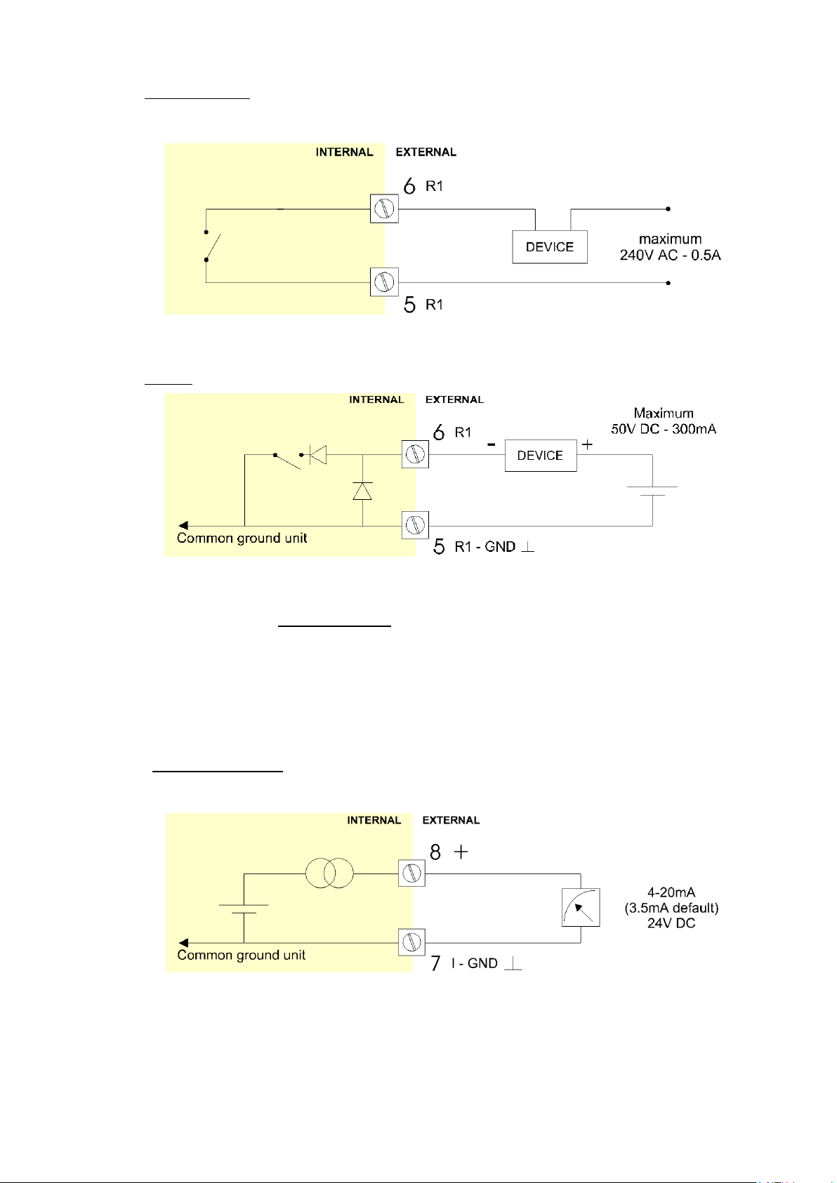
Terminal 05-06; scaled pulse output R1:
Setup 8 (read chapter 3). determines the pulse output function. The maximum pulse frequency of
this output is 500Hz. If a relay output option has been supplied, be sure that the output frequency
does not exceed 5Hz or else the life-time of the relay will be reduced significantly.
Type OA:
An active 24V DC pulse signal output is available with this option.
Max. driving capacity 50mA@24V per output. (Requires power supply type PD/PF/PM).
Fig. 9: Terminal connections - Active output (typical)
FW_F112A_v1702_02_EN
Page 25
Page 25
Type OR:
A mechanical relay output is available with this option.
Max. switch power 240V 0,5A per output. (Requires power supply type PD/PF/PM). Be sure that the
output frequency does not exceed 5Hz, else the relay life time will be reduced significantly.
Fig. 10: Terminal connections - Mechanical relay output (typical)
Type OT:
A passive transistor output is available with this option. Max. driving capacity 300mA@50V DC.
Fig. 11: Terminal connections - Pulse output (typical)
Terminal 07-08; basic POWER SUPPLY - type AP - output loop powered:
Connect an external power supply of 8-30VDC to these terminals or a (0)4-20mA loop.
Do connect the "-" to terminal 7 and the "+" to terminal 8. When power is applied to these terminals,
the (optional) internal battery will be disabled / enabled automatically to extend the battery life time.
Terminal 07-08 analog output (SETUP 8) :
An analog output signal proportional to the flow rate is available as standard.
Type AA:
An active 4-20mA signal proportional to the flow rate is available with this option.
When the output is disabled, a 3.5mA signal will be generated on these terminals.
Max. driving capacity 1000 Ohm @ 24VDC. (Requires power supply type PD/PF/PM).
Fig. 12: Terminal connections - 4-20mA analog output (typical)
FW_F112A_v1702_02_EN
Page 26
Page 26
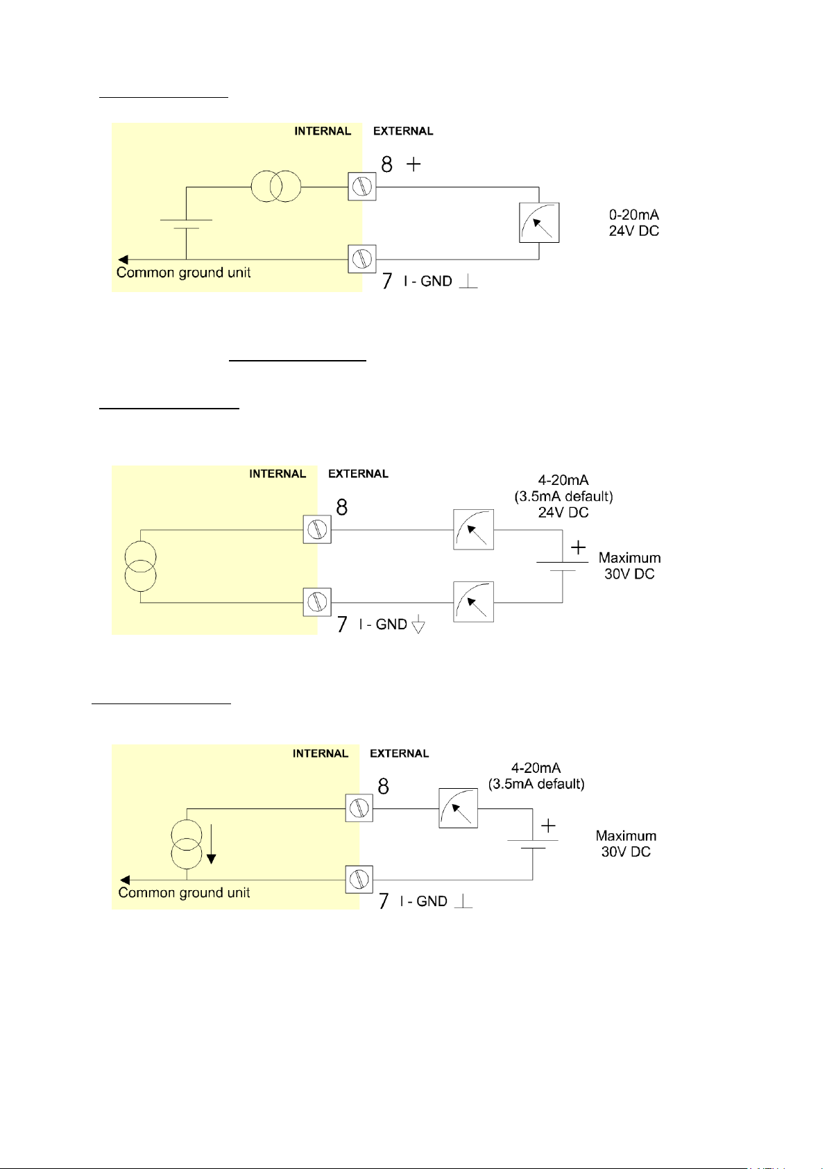
Type AB:
An active 0-20mA signal proportional to the flow rate is available with this option.
Max. driving capacity 1000 Ohm @ 24VDC. (Requires power supply type PD/PF/PM).
Fig. 13: Terminal connections - Active 0-20mA analog output (typical)
Type AF:
For the Intrinsically safe floating 4-20mA signal: please read Chapter 5.
Type AI:
An isolated 4-20mA signal proportional to the flow rate is available with this option.
When the output is disabled, a 3.5mA signal will be generated on these terminals.
Max. driving capacity 1000 Ohm @ 30VDC. This option can be used with a battery powered unit but
the life time of the battery is about 2 -3 years.
Fig. 14: Terminal connections - Isolated 4-20mA analog output (typical)
Type AP:
A passive 4-20mA signal proportional to the flow rate is available with this option. When a power
supply is connected but the output is disabled, a 3.5mA signal will be generated.
Max. driving capacity 1000 Ohm. This output does loop power the unit as well.
Fig. 15: Terminal connections - Passive 4-20mA analog output (typical)
FW_F112A_v1702_02_EN
Page 27
Page 27
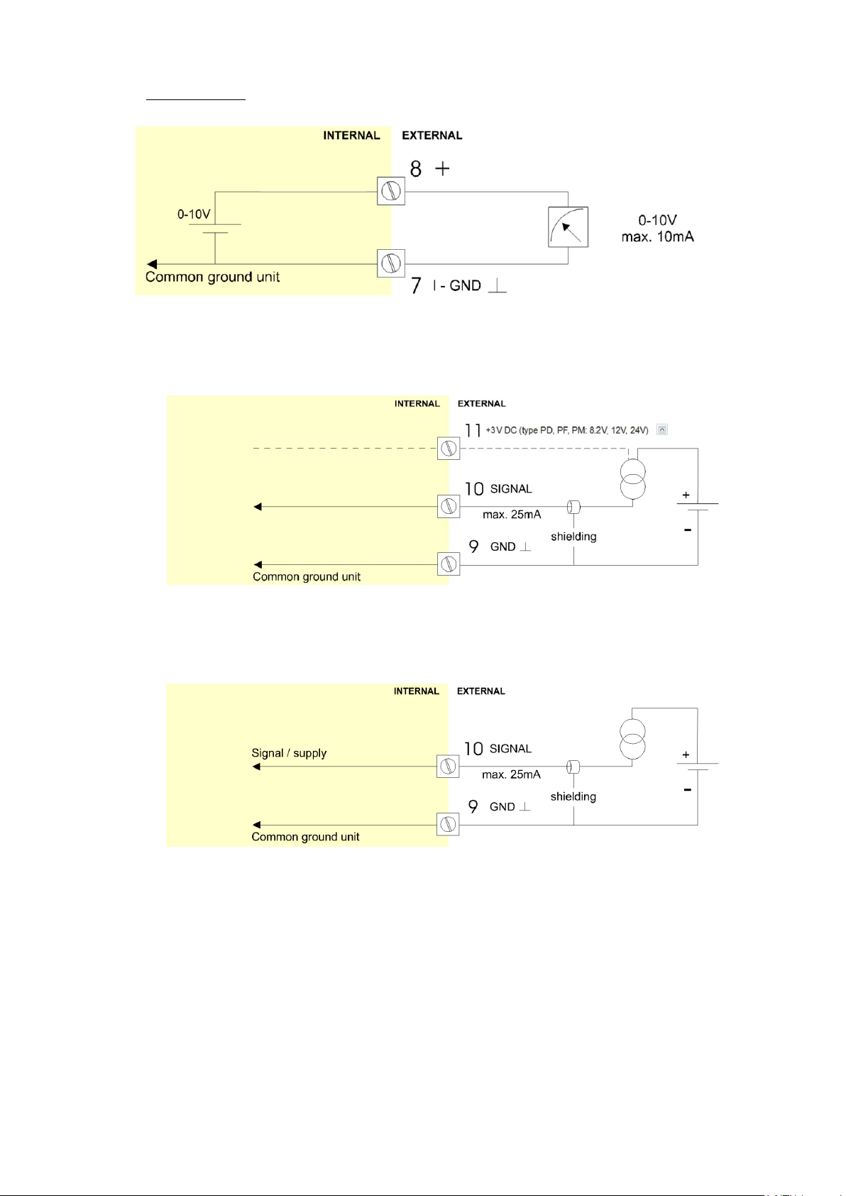
Type AU:
A 0-10VDC signal proportional to the flow rate is available with this option.
Max. load 10mA @ 10VDC. (Requires power supply type PD/PF/PM).
Fig. 16: Terminal connections - Active 0-10V analog output (typical)
Terminal 09-11: Type A – Flowmeter input (general)
The F112-A requires a (0)4-20mA flowmeter signal which will be processed 4 times a second with a
16 bits accuracy. The input is not isolated.
For Intrinsically safe applications (without input loop power): please read chapter 5.
Fig. 17: Terminal connections - Analog signal input (typical)
Terminal 09-10: Type A-PL – Flowmeter input / power supply:
The F112-A-PL requires a 4-20mA flowmeter signal which has a double function:
The signal will be processed 4 times a second with a 16 bits accuracy and the unit will be powered
from the sensor signal (input loop powered). The input is not isolated and not intrinsically safe.
Fig. 18: Terminal connections - Analog signal input – Loop-powered (typical)
FW_F112A_v1702_02_EN
Page 28
Page 28
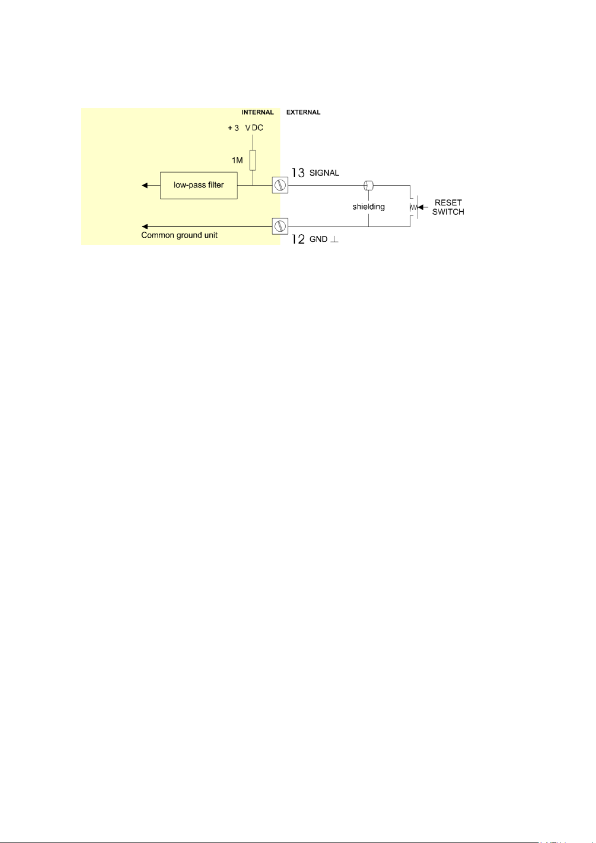
Terminal 12-13: Type IB – external reset:
With this function the total can be reset to zero with an external switch. The Total resets only when
the switch opens. When a Normally Closed (NC) contact is used, the local clear total function is
disabled and a clear total is only possible with the external reset command.
The input must be switched with a potential free contact to the terminal 12.
Fig. 19: Terminal connections - External reset (typical)
Terminal 26-31: type CB / CH / CI / CT - communication RS232 / RS485 / TTL (option):
For connections, refer to figure: Overview of terminal connectors - Standard configuration and options
Full serial communications and computer control in accordance with RS232 (length of cable max. 15
meters) or RS485 (length of cable max. 1200 meters) is possible.
When using the RS232 communication option, terminal 27 is used for supplying the interface.
Please connect the DTR (or the RTS) signal of the interface to this terminal and set it active (+12V).
If no active signal is available it is possible to connect a separate supply between terminals
26 and 27 with a voltage between 8V and 24V.
Terminal 00 - 01: type ZB backlight (option):
If the unit is supplied with a power supply:
type PD, PF or PM, the backlight supply is integrated.
type PX, use the terminals 00 and 01 to supply the backlight.
The backlight intensity is set in the setup menu: Display.
FW_F112A_v1702_02_EN
Page 29
Page 29
For the combined connection of the different supply, input and output circuits, the
instructions in this manual must be observed. From the safety point of view the circuits
shall be considered to be connected to earth.
Certificates, safety values, control drawing and declaration of compliance can be found in
the document named: “Fluidwell F1..-..-XI - Documentation for Intrinsic safety”.
For installation under ATEX directive: this Intrinsically safe device must be installed in
accordance with the latest ATEX directive and product certificate KEMA 03ATEX1074 X.
For installation under IECEx scheme: this Intrinsically safe device must be installed in
accordance the product certificate IECEx DEK 11.0042X.
Exchange of Intrinsically safe battery FWLiBAT-0xx with certificate number
KEMA 03ATEX1071 U or IECEx KEM 08.0005U is allowed in Hazardous Area.
Read chapter 6 for battery replacement instructions.
When the enclosure of the F112-P is made of aluminum alloy, when used in a potentially
explosive atmosphere requiring apparatus of EPL Ga, the indicator shall be installed so,
that even in the event of rare incidents, an ignition source due to impact or friction sparks
between the enclosure and iron/steel is excluded.
When two or more active Intrinsically safe circuits are connected to the indicator, in order
to prevent voltage and/or current addition, applicable to the external circuits, precautions
must be taken to separate the Intrinsically safe circuits in accordance with EN 60079-11.
To maintain the degree of protection of at least IP65 in accordance with IEC 60529,
suitable cable entries and blanking elements must be used and correctly installed.
For enclosures and windows with a high surface resistance, potential charging hazard
exists. Do not rub these surfaces of the indicator. Clean window and enclosure only with a
lint-free cleaning cloth made damp with a mild soap solution.
Chapter 4 shows general information regarding the electrical installation of your indicator.
This chapter gives additional specific information regarding Intrinsically safe installation
and overrules the information given in chapter 4.
Mounting, electrical installation, start-up and maintenance of this device may only be
carried out by trained persons authorized by the operator of the facility. Persons must
read and understand this manual before carrying out its instructions.
This device may only be operated by persons who are authorized and trained by the
operator of the facility. All instructions in this manual are to be observed.
Make sure, the measuring system is correctly wired up according to the wiring diagrams.
Protection against accidental contact is no longer assured when the housing cover is
removed or the panel cabinet has been opened (danger from electrical shock). The
housing may only be opened by trained persons authorized by the operator of the facility.
Take careful notice of the "Safety rules, instructions and precautionary measures" in the
front of this manual.
Special conditions for safe use mentioned in both the certificate and the installation
instructions must be observed for the connection of power to both input and / or output
circuits.
When installing this device in hazardous areas, the wiring and installation must comply
with the appropriate installation standards for your industry.
Study the following pages with wiring diagrams per classification.
5. INTRINSICALLY SAFE APPLICATIONS
5.1. GENERAL INFORMATION AND INSTRUCTIONS
FW_F112A_v1702_02_EN
Page 30
Page 30
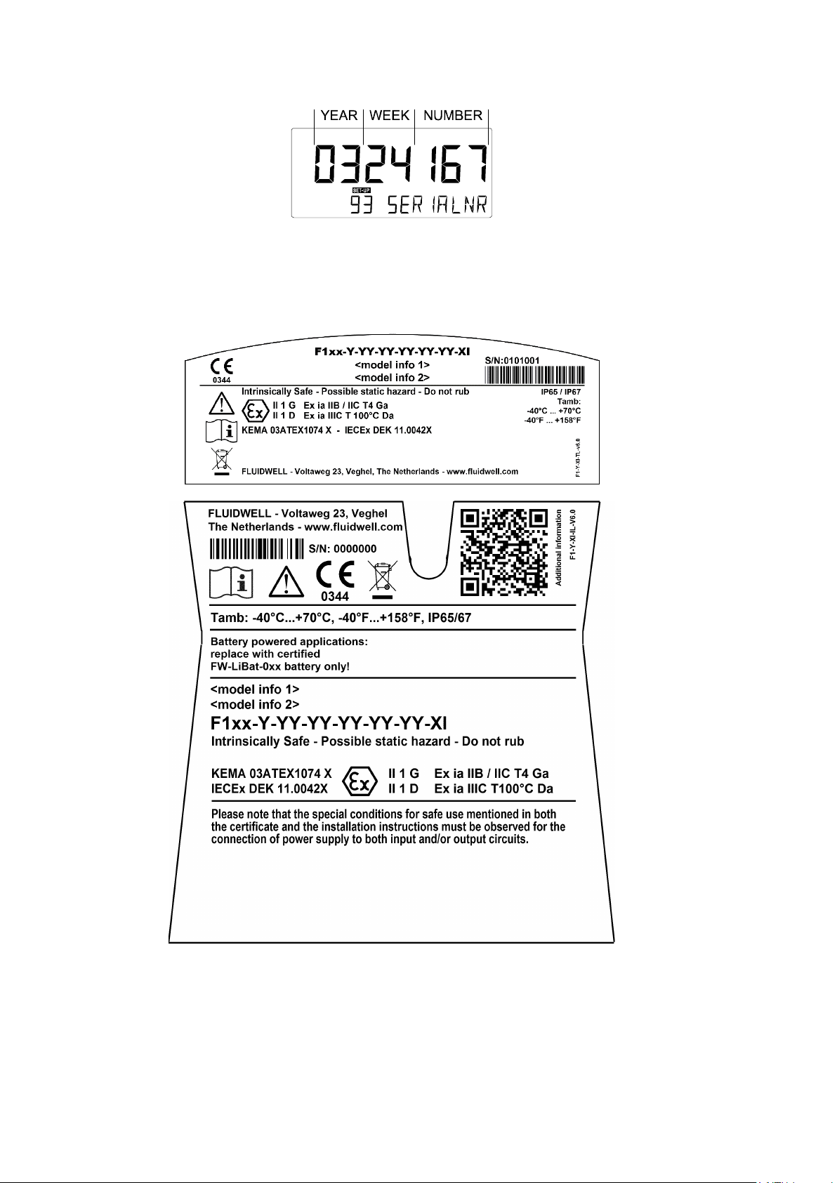
Serial number and year of production
This information can be looked-up in the setup menu: Others.
Fig. 20: Example serial number (typical)
Label information pulse input type – F1xx-..-..-XI (inside and outside the enclosure)
Fig. 21: Label information - Intrinsically safe application (typical)
FW_F112A_v1702_02_EN
Page 31
Page 31
The unit is classified as group IIB/IIIC by default
5.2. TERMINAL CONNECTORS INTRINSICALLY SAFE APPLICATIONS
Classification of the unit as group IIC is only possible under the following conditions:
The indicator is either supplied by
the internal supply (type PC);
the external supply connected to terminals 0 and 1 (type PD);
the circuit supply connected to terminals 7 and 8 (type AP);
The maximum values for any of those circuits are those as defined for group IIB/IIIC;
No other active external Intrinsically safe circuits may be connected to the indicator, with
exception of circuits connected to terminals 3 and 4 and/or terminals 5 and 6; the maximum
values for any of those circuits are those as defined for group IIB/IIIC.
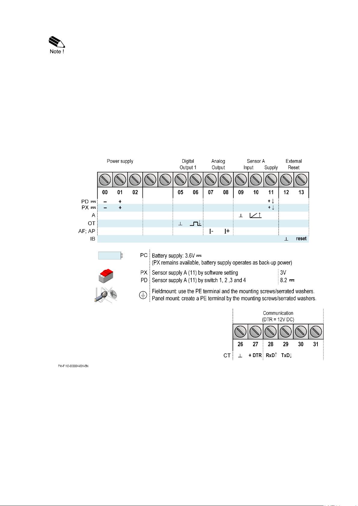
Terminal connectors F112-P-…-XI:
For intrinsically safe applications, consult the safety values in the certificate.
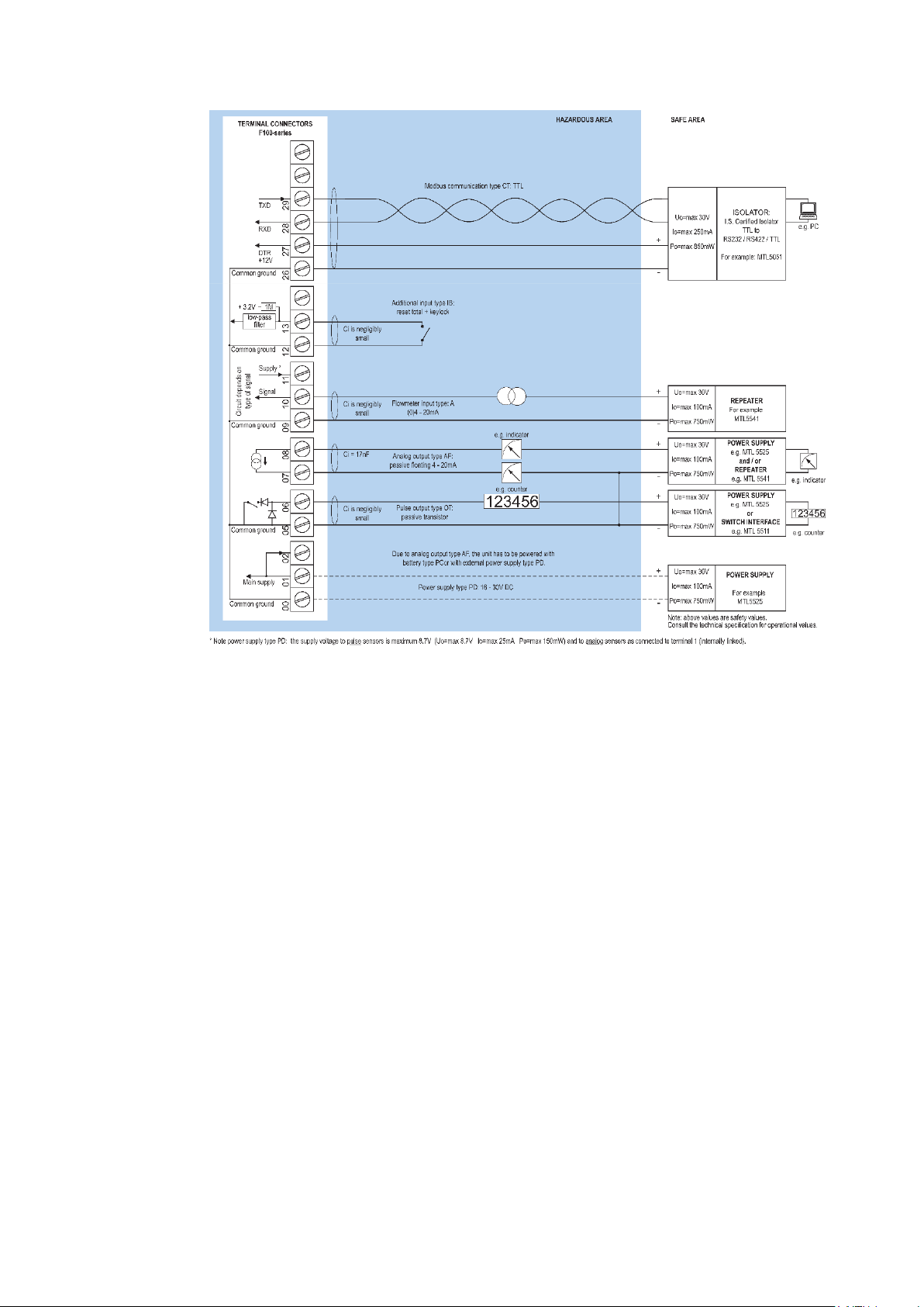
Fig. 22: Overview terminal connectors XI - Intrinsically safe applications
FW_F112A_v1702_02_EN
Page 32
Page 32
Risk of electrocution - High voltage!
Make sure, all the leads to the terminals are disconnected from the F112-P and NEVER
connect the mains power supply to the unit when the protection cover has been removed!
Type PD-XI
Power supply in: 16-30V DC / max. 1W
Switch location (typical)
Sensor
Sensor supply out
A
1 2
off - Coil 1.2V DC; <1mA
Reed 3V DC; <1mA
on - 8.2V DC; 7mA (max)
Explanation Intrinsically safe options:
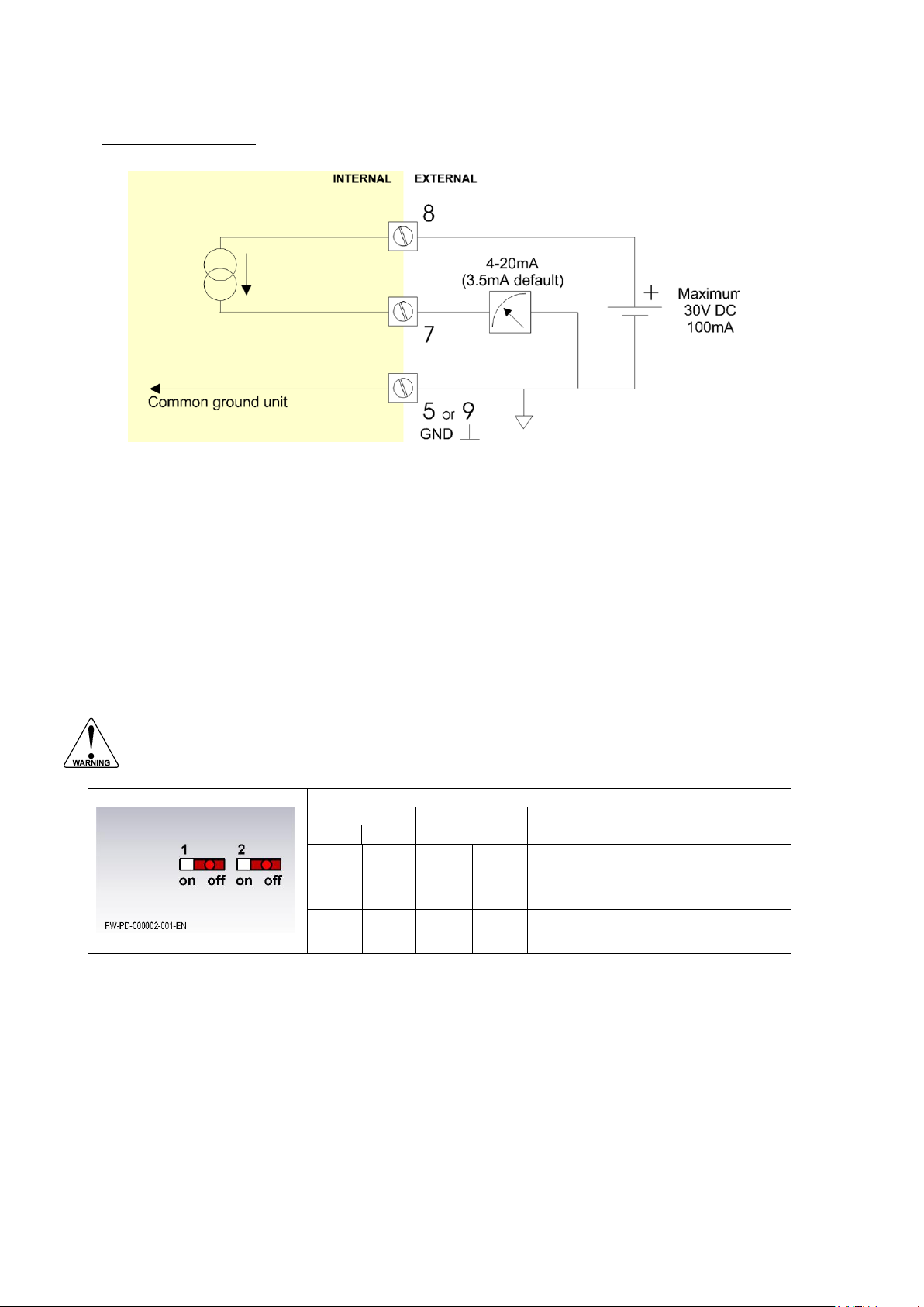
Type AF – Intrinsically safe floating 4-20mA analog output:
A floating 4-20mA signal proportional to the flow rate is available with this option. When the output is
disabled, a 3.5mA signal will be generated. Max. driving capacity 1000 Ohm @ 30V DC.
Fig. 23: Terminal connections - Intrinsically safe floating 4-20mA analog output (typical)
For type PD-XI: It is possible to supply the sensor with different voltages. You can set the voltage
with the switches. Internal power is only applicable for low power sensors (Coil, Reed). The sensor
supply is set by the firmware: 1.2V DC or 3V DC. External power is only available when the main
external power supply is connected. The sensor supply voltage is fixed: 8.2V DC.
Set the sensor supply
1. Make the F112-P safe. If applicable, mind the battery power.
2. Open the F112-P and carefully remove the cable-connectors and the protective cover.
3. Find and set the switches and select the V
as required.
out
4. Close the protective cover and install the cable connectors.
5. Close the F112-P.
Fig. 24: Switch position voltage selection type PD-XI
FW_F112A_v1702_02_EN
Page 33
Page 33
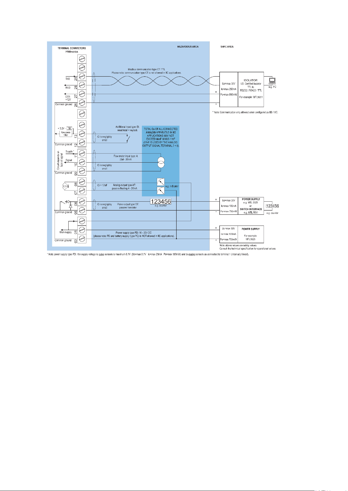
5.3. CONFIGURATION EXAMPLES INTRINSICALLY SAFE APPLICATIONS
Fig. 25: F112-A-AF-CT-IB-OT-(PC)-(PD)-XI - Battery powered - IIB/IIC – IIIC
FW_F112A_v1702_02_EN
Page 34
Page 34
Fig. 26: F112-A-AF-(CT)-IB-OT-PD-XI - External power supply - IIB/IIC – IIIC
FW_F112A_v1702_02_EN
Page 35
Page 35
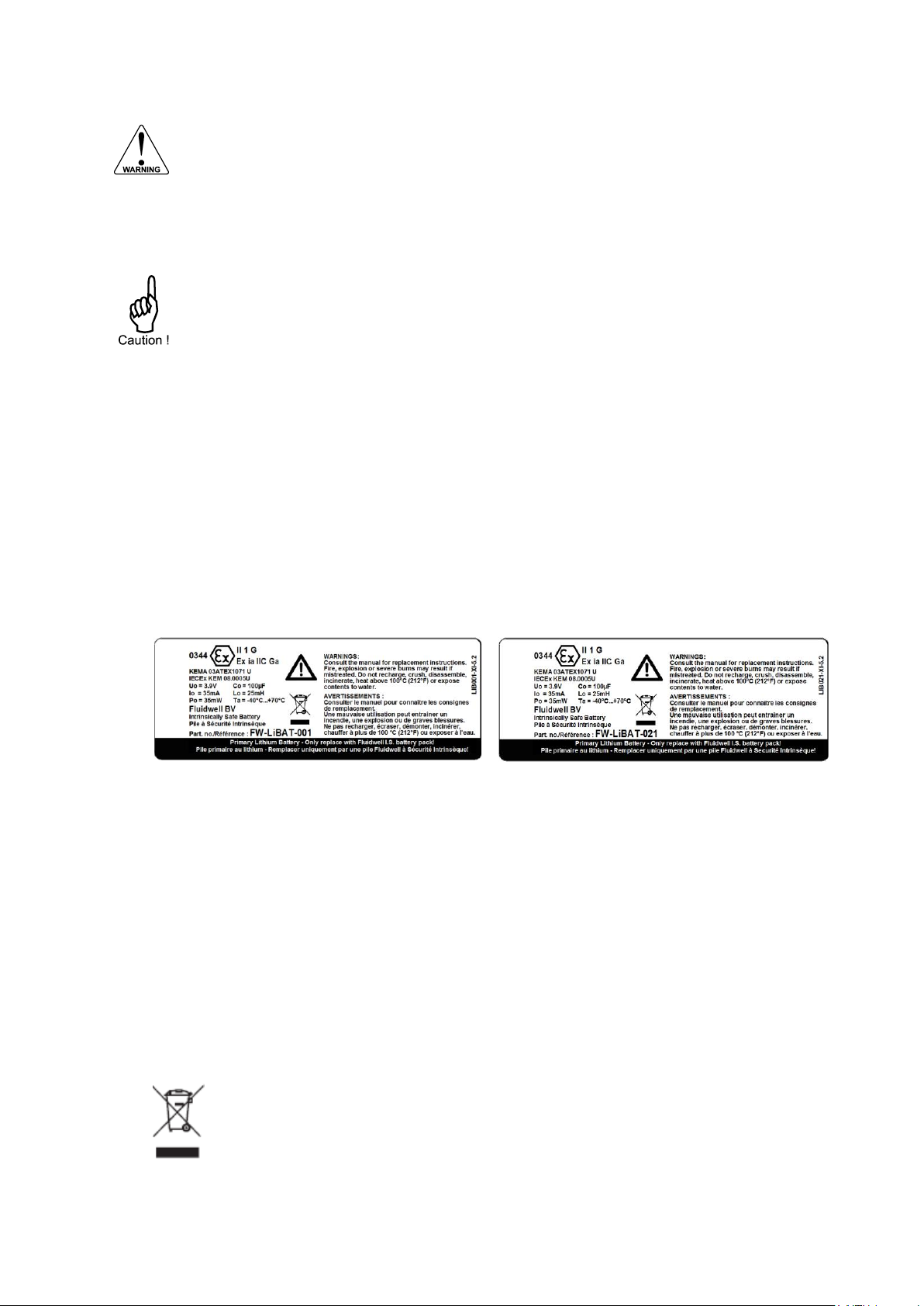
Handle the battery with care. A mistreated battery can become unsafe. Unsafe batteries
can cause (serious) injury to persons.
Only use batteries which are certified for use in hazardous areas. The use of standard
batteries in hazardous area's is not safe and prohibited. Batteries that are regarded as
unsafe can cause (serious) injury to persons and damage to the property.
Mounting, electrical installation, start-up and maintenance of this device may only be
carried out by trained persons authorized by the operator of the facility. Persons must
read and understand this manual before carrying out its instructions.
Only use batteries which are certified for use in hazardous areas. The use of standard
batteries in hazardous area's is not safe and prohibited. Batteries that are regarded as
unsafe can cause (serious) injury to persons and damage to the property.
For use in hazardous areas we advise to apply FW-LiBAT batteries only.
The batteries are used to store electrical energy. The battery is a high power battery which must
be treated carefully. When the battery is mistreated or damaged, there is a risk of a fire, an
explosion and serious burns.
1. Mind that you cannot switch off a battery.
2. Make sure, it is safe to work on the battery system.
3. Handle the battery with the utmost care to prevent a short circuit and damage.
4. Do not recharge, crush, disassemble, incinerate, heat above its rated temperature or expose
the contents to water.
5. Dispose of the battery in accordance with the (inter)national, the manufacturer’s and the plant
owner’s standards and regulations.
6. Read and understand the instructions.
7. Get approval from the safety officer to do the work.
8. Lock-out/Tag-out the unit and related system.
9. Make sure, it is safe to do the work.
REMOVE THE BATTERY
1. If necessary, clean the housing with an antistatic cloth made damp with a mild soap
solution.
2. Let the enclosure dry onto the air.
3. Carefully, open the enclosure.
4. Keep the removed parts in a clean location.
5. Get access to the battery.
6. Find the battery connector and disconnect
the battery from the unit.
7. Remove and keep the battery from the unit.
8. Install an insulation tape over the battery
connector to prevent a short circuit.
INSTALL THE BATTERY
1. Make sure, the new battery is certified for
use in the unit.
2. Work as clean as possible, to prevent
contamination to enter the unit.
3. Carefully, install the battery.
4. Make sure, the battery is correctly locked
into the battery holder.
5. Install the battery connector.
6. Carefully assemble the unit and close the
enclosure.
7. With the enclosure carefully closed, do a test
of the unit.
8. If necessary, get access to the setup menu
and make any adjustments to obtain the
correct settings.
Batteries pose an environmental hazard.
Do not dispose of as general waste or incinerate.
Return used batteries to a recycling point.
5.4 BATTERY REPLACEMENT INSTRUCTIONS
5.4.1. SAFETY INSTRUCTIONS
5.4.2. REPLACE THE BATTERY (HAZARDOUS AREA)
5.4.3. DISPOSAL OF BATTERIES
FW_F112A_v1702_02_EN
Page 36

Page 36
Mounting, electrical installation, start-up and maintenance of this device may only be
carried out by trained persons authorized by the operator of the facility. Persons must
read and understand this manual before carrying out its instructions.
This device may only be operated by persons who are authorized and trained by the
operator of the facility. All instructions in this manual are to be observed.
Make sure, the measuring system is correctly wired up according to the wiring diagrams.
Protection against accidental contact is no longer assured when the housing cover is
removed or the panel cabinet has been opened (danger from electrical shock). The
housing may only be opened by trained persons authorized by the operator of the facility.
Take careful notice of the "Safety rules, instructions and precautionary measures" in the
front of this manual.
6. MAINTENANCE
6.1. GENERAL DIRECTIONS
The F112-P does not require special maintenance unless it is used in low-temperature applications
or surroundings with high humidity (above 90% annual mean). It is the users responsibility to take all
precautions to dehumidify the internal atmosphere of the F112-P in such a way that no condensation
will occur, e.g. to put a dose of desiccant (drying agent) inside the enclosure just before closing it.
Furthermore, it is required to replace the desiccant periodically as advised by its supplier.
Battery life-time:
It is influenced by several issues :
Type of sensor (read chapter 3): NPN and PNP inputs consume more energy than coil inputs;
Input frequency: the higher the frequency, the shorter the battery life-time;
Analog output signal; be sure that an external power supply is connected or that the function is
disabled if not in use; or else it will have a major influence on the battery life-time;
Display update: fast display update uses significantly more power;
Pulse output and communications;
Low temperatures; the available power will be less due to battery chemistry.
It is strongly advised to disable the unused functions.
Check periodically:
The condition of the enclosure, cable glands and front panel.
The input/output wiring for reliability and aging symptoms.
The process accuracy. As a result of wear and tear, re-calibration of the flowmeter might be
necessary. Do not forget to re-enter any subsequent Span and linearization alterations.
The indication for low-battery.
Clean window and enclosure only with a lint-free cleaning cloth made damp with a mild soap
solution.. Do not use any aggressive solvents as these might damage the coating.
6.2. REPAIR
This product cannot be repaired by the user and must be replaced with an equivalent certified
product. Repairs should only be carried out by the manufacturer or his authorized agent.
6.3. REPAIR POLICY
If you have any problem with your Fluidwell product and you wish to repair it, please follow the
procedure below:
a. Obtain a Return Material Authorization (RMA) from your supplier or distributor Together with the
RMA, you need to complete a repair form to submit detailed information about the problem.
b. Send the product, within 30 days, to the address provided with the RMA. The physical return of
your repair can only take place after the authorization of your repair application, as confirmed by
the RMA number.
If the product is within the warranty period, it will be repaired or exchanged and returned within three
weeks. If the product is no longer under warranty, you will receive a repair estimate.
FW_F112A_v1702_02_EN
Page 37
Page 37
Display
Type
High intensity reflective numeric and alphanumeric LCD, UV-resistant.
Digits
Seven 17mm (0.67") and eleven 8mm (0.31"). Various symbols and measuring units.
Refresh rate
User definable: 8 times/sec - 30 secs.
Type ZB
LCD with LED backlight. Improved readability in full sunlight and darkness.
Power requirements: 12-24V DC + 10% or type PD, PF, PM. Power consumption max. 1 Watt.
Enclosures
General
Control Keys
Painting
Die-cast aluminum or GRP (Glassfibre Reinforced Polyamide) enclosure with Polycarbonate
window, silicone and EPDM gaskets. UV stabilized and flame retardant material.
Three industrial micro-switch keys. UV-stabilized silicone keypad.
Aluminum enclosure only: UV-resistant 2-component industrial painting.
Panel-mount enclosures
Classification
Panel cut-out
Type HC
Type HB
Dimensions: 130 x 120 x 60mm (5.10" x 4.72" x 2.38") – LxHxD.
IP65 / TYPE 4(X)
115 x 98mm (4.53" x 3.86") LxH.
GRP panel-mount enclosure
Aluminum panel-mount enclosure
Field/wall-mount enclosures
Classification
Aluminum enclosures
Type HA
Type HM
Type HN
Type HO
Type HP
Type HT
Type HU
Type HZ
GRP enclosures
Type HD
Type HE
Type HF
Type HG
Type HH
Dimensions: 130 x 120 x 75mm (5.10” x 4.72” x 2.95”) – LxHxD.
IP67 / TYPE 4(X)
Drilling: 2x PG9 – 1x M20.
Drilling: 2x M16 – 1x M20.
Drilling: 1x M20.
Drilling: 2x M20.
Drilling: 6x M12.
Drilling: 1x ½”NPT.
Drilling: 3x ½”NPT.
No drilling.
No drilling.
Drilling: 2x 16mm (0.63”) – 1x 20mm (0.78”).
Drilling: 1x 22mm (0.87”).
Drilling: 2x 20mm (0.78”).
Drilling: 6x 12mm (0.47”).
Operating temperature
Operational
-40°C to +80°C (-40°F to +176°F)
Intrinsically safe
-40°C to +70°C (-40°F to +158°F)
Relative humidity
90%, no condensation allowed.
Power supply
Type AP
8-30V DC; Power consumption max. 0.5 Watt.
Type PB
Lithium battery - life-time depends upon settings - up to 5 years.
Type PC
Intrinsically safe lithium battery - life-time depends upon settings - up to 5 years.
Type PD
8-24V AC / 8-30V DC; Power consumption max. 5 Watt.
Type PD-ZB
10-24V AC / 12-30V DC; Power consumption max. 5 Watt.
Type PD-XI
16-30V DC; Power consumption max. 1 Watt.
Type PF
15-24V AC / 20-30V DC; Power consumption max. 15 Watt.
Type PM
115-230V AC; Power consumption max. 15 Watt.
Type PX
8-30V DC; Power consumption max. 0.75 Watt.
Type PX-ZB
12-30V DC; Power consumption max. 1.5 Watt.
Type PX-XI
8-30V DC; Power consumption max. 0.75 Watt.
Note I.S. applications
For Intrinsically safe applications, consult the safety values in the certificate.
Sensor excitation
Type PB / PC / PX
3V DC for low power pulse signals and 1.2V DC for coil pick-up.
Type PD
1.2; 3; 8.2; 12; 24V DC - max. 50mA@24V DC
Type PD-XI
Intrinsically safe: Pulse signals: 1.2; 3; 8.2 - max. [email protected] DC.
Type PF / PM
1.2; 3; 8.2; 12; 24V DC - max. 400mA@24V DC.
GENERAL
APPENDIX A: TECHNICAL SPECIFICATION
FW_F112A_v1702_02_EN
Page 38
Page 38
Terminal connections
Type:
Removable plug-in terminal strip. Wire max. 1.5mm2 and 2.5mm2
Data protection
Type
EEPROM backup of all setting. Backup of running totals every minute.
Data retention at least 10 years.
Password
Configuration settings can be password protected.
Hazardous area
Intrinsically safe
Type XI
ATEX approval :
II 1 G Ex ia IIB/IIC T4 Ga
II 1 D Ex ia IIIC T100°C Da
IECEx approval :
Ex ia IIB/IIC T4 Ga
Ex ia IIIC T100°C Da
Explosion proof
Type XD/XF
ATEX approval ref: II 2 EEx d IIB T5. Weight appr. 15kg.
Dimensions of enclosure: 350 x 250 x 200mm (13.7” x 9.9” x 7.9”) LxHxD.
Directives and
Standards
EMC
EN 61326-1; FCC 47 CFR part 15
LVD
EN/IEC 61010-1
ATEX / IECEx
EN/IEC 60079-0; EN/IEC 60079-11
RoHS
EN 50581
IP & NEMA
EN 60529; NEMA 250
Flowmeter
Type A
(0)4-20mA - with signal calibration feature at any current within the range.
Accuracy
Resolution: 16 bit.. Error < 0.025mA / ±0.125% FS. Low level cut-off programmable.
Span
0.000010 - 9999999 with variable decimal position.
Update time
Four times a second.
Voltage drop
2.5 Volt
Relationship
Linear and square root calculation.
Note
External power to sensor is required; e.g. type PD.
Linearization
15 positions with interpolation function;
Meter-Factor 0.000001 - 9.999999 versus Percentage (0)4-20mA.
15BReset
Type IB
Make contact - external reset totalizer. Additional functionality to lock the RESET button of the
keyboard (as long as this contact is being made).
Duration
Minimum 100mSec. to reset Total.
INPUTS
FW_F112A_v1702_02_EN
Page 39
Page 39
Analog output
Function
transmitting (linearized) flow rate.
Accuracy
10 bit. Error < 0.05% - update 8 times a second. Software function to calibrate the 4.00mA and
20.00mA levels precisely.
Load
max. 1 kOhm
Option AA
Active 4-20mA output (requires option PD or PM).
Option AB
Active 0-20mA output (requires option PD or PM).
Option AF
Floating 4-20mA output for Intrinsically Safe applications (isolated output)
Option AI
Galvanically isolated output - also for battery powered models.
Option AU
Active 0-10V output (requires option PD or PM).
Transistor output(s)
Pulse output
Max. frequency 500Hz. Pulse length user definable between 0.001 up to 9.999 seconds.
Function
One pulse output - transmitting accumulated total.
Type OA
Active 24V DC transistor output; max. 50mA per output (requires type AA + PD, PF or PM).
Type OR
Isolated mechanic relay output; max. switch power 230V AC - 0,5A (requires type PF or PM).
Type OT
Passive transistor output - not isolated. Load max. 50V DC - 300mA.
Type OR
Electro-mechanical relay output; max. switch power 230V AC - 0,5A
(requires option PF or PM).
18BCommunication option
Protocol
bus-rtu; bus-asc
Speed
1200; 2400; 4800; 9600
Addressing
1 - 247
Type CB
RS232
Type CH
RS485 2-wire
Type CI
RS485 4-wire
Type CT
TTL Intrinsically safe communication.
Type CX
no communication.
Operator functions
Displayed functions
linearized total and/or flow rate.
linearized total and linearized accumulated total.
total can be reset to zero by pressing the CLEAR-key twice.
Total
Digits
7 digits.
Units
L; m3; kg; lb; GAL; USGAL; bbl; no unit
Decimals
0000000; 111111.1; 22222.22; 3333.333
Note
total can be reset to zero.
Accumulated total
Digits
11 digits.
Units / decimals
according selection for total.
Flowrate
Digits
7 digits.
Units
mL; L; m3; mg; g; kg; ton; gal; bbl; lb; cf; rev; - - - - (no unit); scf; nm3; nL; p
Decimals
0000000; 111111.1; 22222.22; 3333.333
Time units
/sec; /min; /hour; /day
OUTPUTS
OPERATIONAL
FW_F112A_v1702_02_EN
Page 40

Page 40
APPENDIX B: PROBLEM SOLVING
In this appendix, several problems are included that can occur when the F112-A is going to be
installed or while it is in operation.
Analog output does not function properly:
Check:
is the analog output enabled?
are the flow-levels programmed correctly?
connection of the external power-supply according to the specification.
Pulse output does not function:
Check:
Pulse per “x” quantity (amount); is the value programmed reasonable and will the maximum
output be under 20Hz?
Amount; is the external device able to recognize the selected amount?
Flow rate displays "0 / zero" while there is flow (total is counting):
Check:
are the Span and time unit correct?
Linearization does not work:
Check:
is the function enabled?
are all M-Factors and the frequency entered correctly?
The password is unknown:
If the password is not 1234, there is only one possibility left: call your supplier.
ALARM
When the alarm flag starts to blink an internal alarm condition has occurred. Press the "select
button" several times to display the error code. When multiple errors arise at the same time, their
error codes are added and their sum is shown. The digital [d] codes are:
Not recoverable by the end user:
[d] 0 = no error;
[d] 1 = display error;
[d] 2 = data-storage error;
[d] 3 = error 1 + error 2 simultaneously;
[d] 4 = initialization error.
[d] 10 = linearization error (calculated M-Factor out of range)
For a not recoverable error, keep the error code at hand and contact your supplier.
FW_F112A_v1702_02_EN
Page 41
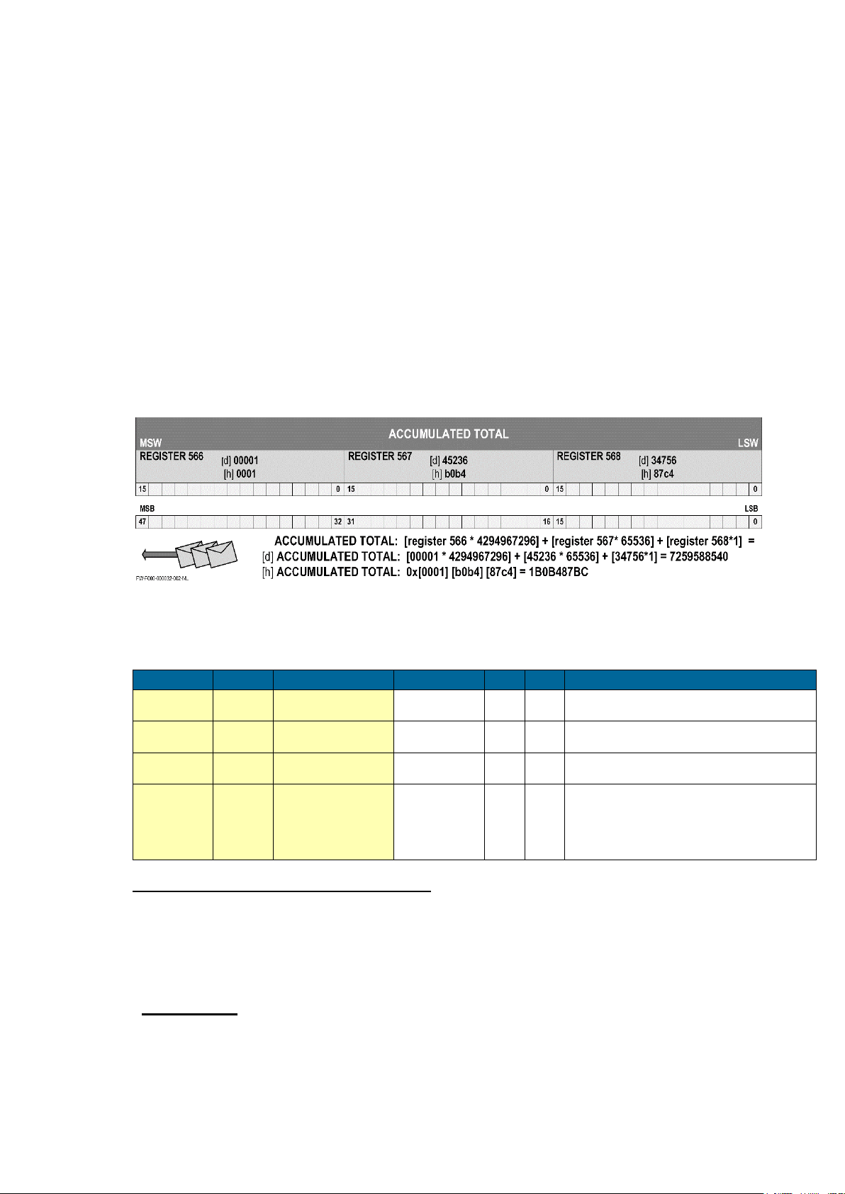
Page 41
PDU ADDRESS
REGISTER
VARIABLE
NO. REGISTERS
R/W
TYPE
VALUE / REMARKS
[d] 572
[h] 0x23C
40573
flow rate
2
r
uint32
0…9999999, Representation: unit, time,
decimals depending on variables 48, 49, 50
[d] 566
[h] 0x236
40567
total 3 r*
uint48
0…9999999999, Representation: unit,
decimals depending on variables 32, 33
[d] 560
[h] 0x230
40561
accumulated total
3
r
uint48
0…99999999999999, Representation: unit,
decimals depending on variables 32, 33
[d] 516
[h] 0x204
40517
error status (bitfield)
1
r
uint16
0x0001=Display error
0x0002=EEPROM error
0x0004=EEPROM initialization error
0x0010=Linearization error
(calculated M-factor out of range)
APPENDIX C: COMMUNICATION VARIABLES
GENERAL
The product is fitted with the Modbus communication protocol and can be equipped with various
physical interfaces like RS485 and RS232 (please see device datasheet for available options).
The tables below show the various variables that can be accessed through the communication.
Currently, the function codes supported are:
function code 3 “Read Holding Registers” (4x references);
function code 16 “Preset Multiple Registers” (4x references).
The table below shows the Modbus PDU addresses in a decimal format, followed by its hexadecimal
representation (0x0000). When the PLC address range is required (4x references are typically used
by PLCs), please add a value of 40001 to the Modbus PDU address. E.g. reading the serial number
of the product with PLC-based addressing means: 165 + 40001 = register 40166.
The variables that consist of a multiple register must always read/write in 1 single action!
Refer to the illustration:
For this example it is assumed that the variable accumulated total has 3 registers (words) with
address 566, 567 and 568. When a transmission is done, register 566, which acts as the MSW,
arrives first with bit 15 which is the MSB of the lowest addressed word, but is also the MSB (bit 47)
of the complete variable that represents the Accumulated total.
Although most Modbus Masters will support variables that span 2 registers, variables spanning more
registers sometimes require you to manually calculate the resulting value.
For additional information regarding using your Modbus device, please read our ’General Modbus
Communication Protocol’ and ‘Modbus troubleshooting guide’ that are available through our website
or your distributor.
Runtime variables
Reading flow rate, total or accumulated total: The returned values are given including the
decimals and represent the actual value. The given value may differ from the value that is shown on
the display – this is due to the fact that the display is limited in the number of digits and may have a
slower update rate set.
For example when two decimals are selected for total and total has a value of 123456,78 the display
will show 23456,78 while communication will read a “total” of 12345678 (note that the decimals
should be adapted according the setting in “total decimals” which is in this case 2).
* Clearing total: It is possible to clear the total counter by means of writing a value of 0 to all the 3
registers of total/flow rate in a single write action. Writing any other value will result in the reply of an
error message because the registers of total/flow rate are during operation read-only.
FW_F112A_v1702_02_EN
Page 42
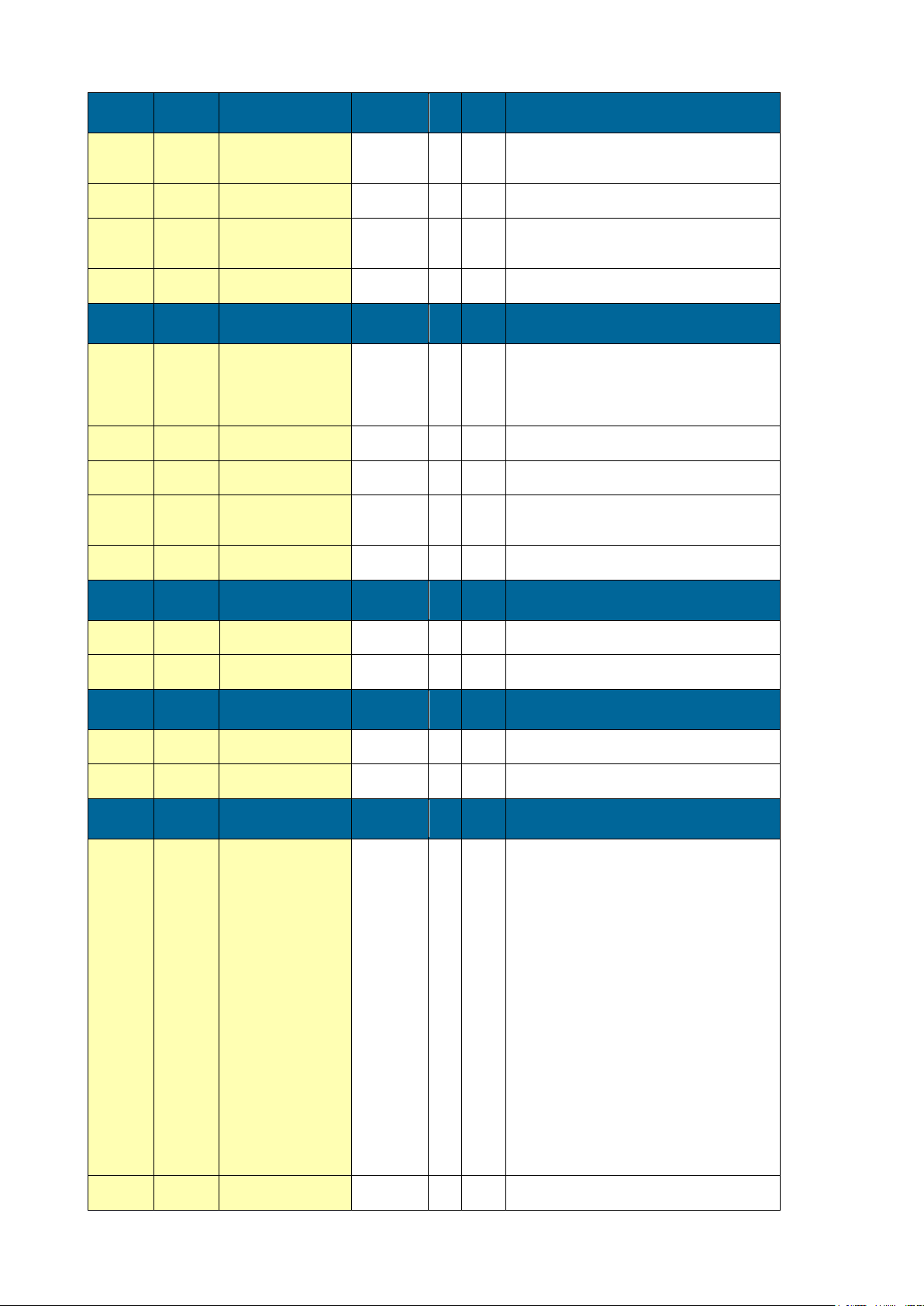
Page 42
PDU
ADDRESS
REGISTER
VARIABLE
TOTAL
NO.
REGISTERS
R/W TYPE VALUE / REMARKS
[d] 32
[h] 0x020
40033
unit 1 r/w
uint16
0=none
1=L
2= m3
3=kg
4= lb
5=gal
6= US GAL
7=bbl
[d] 33
[h] 0x021
40034
decimals
1
r/w
uint16
0…3
[d] 34
[h] 0x022
40035
span 2 r/w
uint32
1...9999999
Representation: 0.000001…9999999 depending on
variable 54: decimals span.
[d] 37
[h] 0x025
40038
decimals span
1
r/w
uint16
0…6
PDU
ADDRESS
REGISTER
VARIABLE
FLOWRATE
NO.
REGISTERS
R/W TYPE VALUE / REMARKS
[d] 48
[h] 0x030
40049
unit 1 r/w
uint16
0=mL
1=L
2= m3
3=mg
4=g
5=kg
6=ton
7=GAL
8=bbl
9=lb
10=cf
11=rev
12=none
13=scf
14=NM3
15=NL
16=p
[d] 49
[h] 0x031
40050
time unit
1
r/w
uint16
0=/sec
1=/min
2=/hour
3=/day
[d] 50
[h] 0x032
40051
decimals
1
r/w
uint16
0…3
[d] 51
[h] 0x033
40052
span 2 r/w
uint32
1...9999999
Representation: 0.000001…9999999
depending on variable 54: decimals span.
[d] 54
[h] 0x036
40055
decimals span
1
r/w
uint16
0…6
PDU
ADDRESS
REGISTER
VARIABLE
DISPLAY
NO.
REGISTERS
R/W TYPE VALUE / REMARKS
[d] 64
[h] 0x040
40065
display function
1
r/w
uint16
0=total
1=flow rate
[d] 67
[h] 0x043
40068
backlight brightness
1
r/w
uint16
0=off
1=20%
2=40%
3=60%
4=80%
5=100%
PDU
ADDRESS
REGISTER
VARIABLE
POWER MANAGEMENT
NO.
REGISTERS
R/W TYPE VALUE / REMARKS
[d] 80
[h] 0x050
40081
LCD update time
1
r/w
uint16
0=fast
1=1sec
2=3sec
3=15sec
4=30sec
5=off
[d] 81
[h] 0x051
40082
power mode
1
r/w
uint16
0=operational
1=shelf
PDU
ADDRESS
REGISTER
VARIABLE
LINEARIZATION
NO.
REGISTERS
R/W TYPE VALUE / REMARKS
[d] 1024
[h] 0x400
41025
percentage/M-factor
3
r/w
uint48
The linearization table is an INDEXED variable.
Reading and writing the entries of the linearization
tables is done by first selecting the entry through
the index. Valid values for the index are 0…14,
which correspond with the linearization table entries
1 through 15. Indexes outside this range will result
in an error being sent back.
(See the communication-section of this appendix for
setting the index and its extended functionality
through variable 150 and 149).
The 3 registers represent a structure containing 2
variables of each 3 bytes. The three least significant
bytes (PDU address 1024 and LSB of PDU address
1025) contain the percentage part, the three most
significant bytes (MSB of PDU address 1025 and
PDU address 1026) contain the M-factor part.
Valid range for the percentage is (0)4-20mA..
A value of 0 for percenatge means that entry is
disabled.
Valid range for the M-factor 0.000000 to 9.999999.
[d]1038
[h]0x40E
41039
Linearization on/off
1
r/w
uint16
0=disable
1=enable
Setup variables
FW_F112A_v1702_02_EN
Page 43
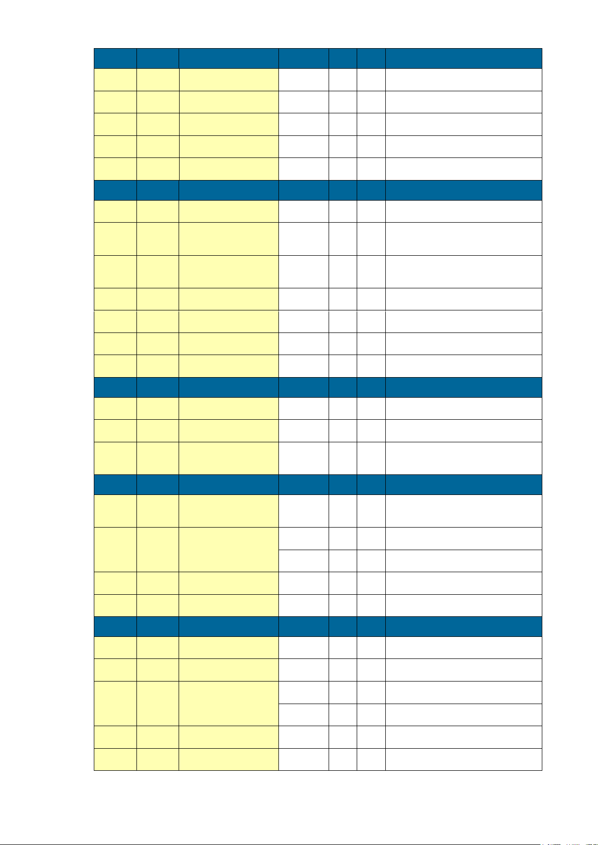
Page 43
PDU
ADDRESS
REGISTER
VARIABLE
FLOWMETER
NO.
REGISTERS
R/W TYPE
VALUE / REMARKS
[d] 98
[h] 0x062
40099
formula
1
r/w
uint16
0=linear
1=square root
[d] 99
[h] 0x063
40100
filter 1 r/w
uint16
1...99
[d] 100
[h] 0x064
40101
cut-off 1 r/w
uint16
0...999
Representation: 0.0 – 99.9%
[d] 102
[h] 0x066
40103
calibrate low
1
r/w
uint16
0=cal set
1=calibrate
2=default
[d] 103
[h] 0x067
40104
calibrate high
1
r/w
uint16
0=cal set
1=calibrate
2=default
PDU
ADDRESS
REGISTER
VARIABLE
ANALOG
NO.
REGISTERS
R/W TYPE
VALUE / REMARKS
[d] 112
[h] 0x070
40113
analog output
1
r/w
uint16
0=disable
1=enable
[d] 113
[h] 0x071
40114
minimum rate
2
r/w
uint32
0…9999999
Representation: unit, time, decimals
depending on variables 48, 49, 50
[d] 116
[h] 0x074
40117
maximum rate
2
r/w
uint32
0…9999999
Representation: unit, time, decimals
depending on variables 48, 49, 50
[d] 119
[h] 0x077
40120
cut off percentage
1
r/w
uint16
0...99
Representation: 0.0 – 9.9%
[d] 120
[h] 0x078
40121
tune minimum rate
1
r/w
uint16
0...9999
[d] 122
[h] 0x07A
40123
tune maximum rate
1
r/w
uInt16
0...9999
[d] 127
[h] 0x07F
40128
filter 1 r/w
uint16
1...99
PDU
ADDRESS
REGISTER
VARIABLE
PULSE
NO.
REGISTERS
R/W TYPE
VALUE / REMARKS
[d] 128
[h] 0x080
40129
pulse width
1
r/w
uint16
0…9999
Representation: 0.001 – 9.999 sec
[d] 133
[h] 0x085
40134
decimals
1
r/w
uint16
0…3
[d] 130
[h] 0x082
40131
amount 2 r/w
uint32
1...9999999
Representation: 0.001…9999999
depending on variables 133, 32
PDU
ADDRESS
REGISTER
VARIABLE
COMMUNICATION
NO.
REGISTERS
R/W TYPE
VALUE / REMARKS
[d] 144
[h] 0x090
40145
speed (Baudrate)
1
r/w
uint16
0=1200
1=2400
2=4800
3=9600
4=9600HP
5=19200
6=38400
[d] 145
[h] 0x091
40146
Modbus address
1
r/w
uint16
1…247
[d] 146
[h] 0x092
40147
Modbus mode
1
r/w
uint16
0: ASCII
1: RTU
2: OFF
[d] 247
[h] 0x0F7
40248
databits
1
r/w
uint16
0=7bits
1=8bits
[d] 248
[h] 0x0F8
40249
parity 1 r/w
uint16
0=none
1=even
2=odd
PDU
ADDRESS
REGISTER
VARIABLE
OTHERS
NO.
REGISTERS
R/W TYPE VALUE / REMARKS
[d] 173
[h] 0x0AD
40174
model number
1
r
uint16
0…9999
[d] 160
[h] 0x0A0
40161
model suffix
1
r
char
Representation: ASCII character
[d] 162
[h] 0x0A2
40163
firmware version
2
r
uint32
0…999999
Representation: nn:nn:nn
[d] 165
[h] 0x0A5
40166
serial no
2
r
uint32
0…9999999
Representation: nnnnnnn
[d] 168
[h] 0x0A8
40169
password
1
r
uint16
0…9999
[d] 170
[h] 0x0AA
40171
tag-nr 2 r/w
uint32
0...9999999
Representation: nnnnnnn
FW_F112A_v1702_02_EN
Page 44
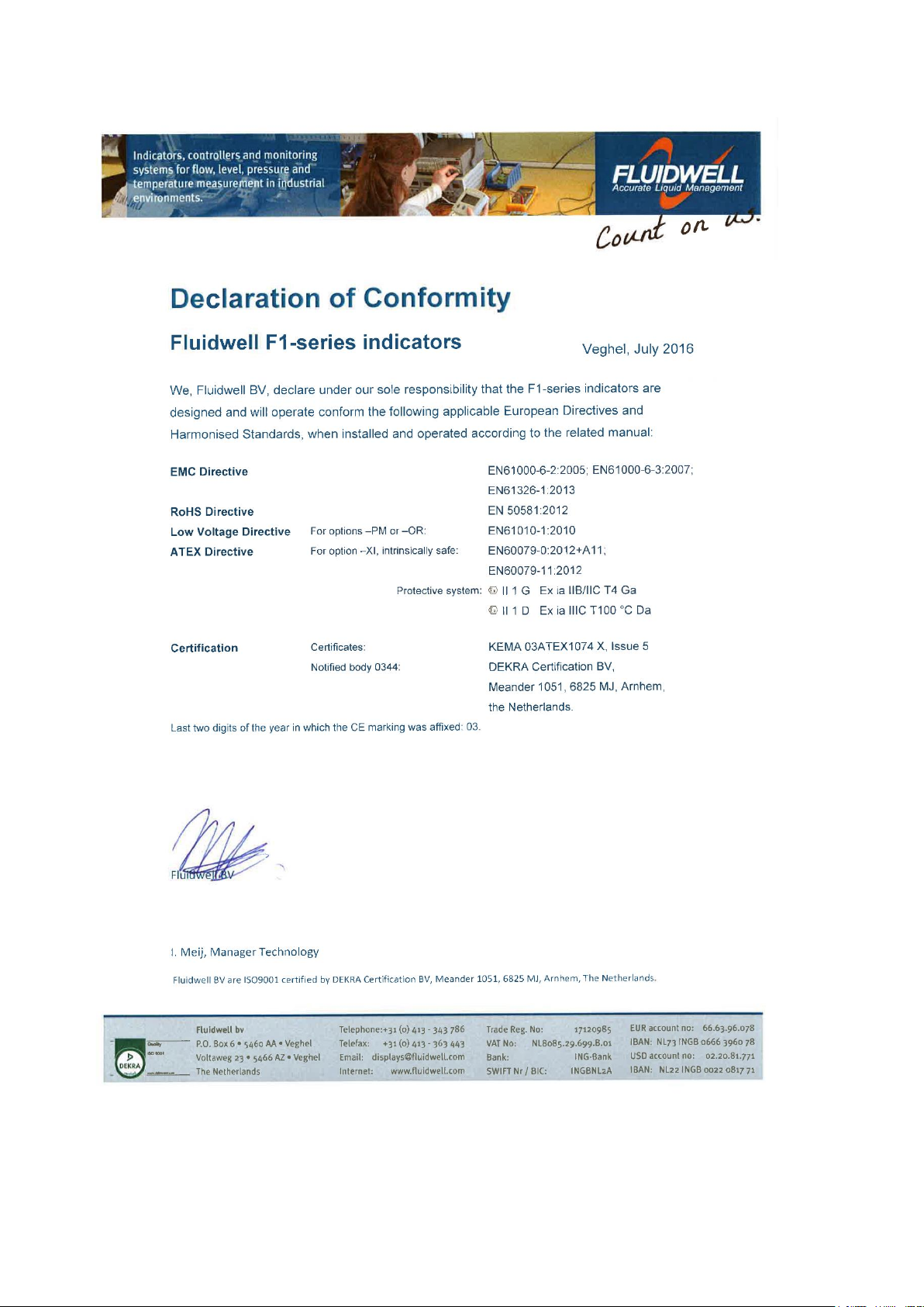
Page 44
APPENDIX D: DECLARATION OF CONFORMITY
FW_F112A_v1702_02_EN
Page 45

Page 45
INDEX OF THIS MANUAL
accumulated Total ......................................... 7
actual settings ....................................... 46, 47
analog
floating output. .......................................... 32
flowrate min. .............................................. 14
intrinsically safe output. ............................ 32
tune / calibrate .......................................... 15
Analog output .............................................. 25
backlight
density ....................................................... 12
battery life time ............................................ 36
Clear Total ..................................................... 7
communication ............................................ 28
family-specific variables ...................... 41, 44
Dimension enclosures ................................. 18
display
function ..................................................... 12
external reset option .................................... 28
filter .............................................................. 12
flowmeter ..................................................... 12
Flowmeter input ........................................... 27
Flowrate ......................................................... 7
Installation ................................................... 17
Intrinsic safety ....................................... 29, 31
Intrinsically Safe options ............................. 32
IP classification............................................ 17
Low-battery alarm ......................................... 7
maintenance ................................................ 36
model ........................................................... 16
operational ................................. 6, 8, 9, 17, 36
operator level................................................. 7
pass code .............................................. 16, 40
Problem solving ........................................... 40
pulse output
pulse length / period time ......................... 15
Pulse output ................................................ 24
serial number............................................... 16
tagnumber ................................................... 16
Technical specification ................................ 37
total
Span ......................................................... 11
Total .............................................................. 7
version software .......................................... 16
LIST OF FIGURES IN THIS MANUAL
Fig. 1: Typical application ......................................................................................................................5
Fig. 2: Control Panel ..............................................................................................................................6
Fig. 3: Process information (typical) ......................................................................................................7
Fig. 4: Low-battery alarm (typical) .........................................................................................................7
Fig. 5: Aluminum enclosures - Dimensions ........................................................................................ 18
Fig. 6: GRP enclosures - Dimensions ................................................................................................ 19
Fig. 7: Overview of terminal connectors - Standard configuration and options ................................. 23
Fig. 8: Sensor supply voltage - Switch setting ................................................................................... 24
Fig. 9: Terminal connections - Active output (typical) ........................................................................ 24
Fig. 10: Terminal connections - Mechanical relay output (typical) ..................................................... 25
Fig. 11: Terminal connections - Pulse output (typical) ....................................................................... 25
Fig. 12: Terminal connections - 4-20mA analog output (typical)........................................................ 25
Fig. 13: Terminal connections - Active 0-20mA analog output (typical) ............................................. 26
Fig. 14: Terminal connections - Isolated 4-20mA analog output (typical) .......................................... 26
Fig. 15: Terminal connections - Passive 4-20mA analog output (typical) .......................................... 26
Fig. 16: Terminal connections - Active 0-10V analog output (typical) ................................................ 27
Fig. 17: Terminal connections - Analog signal input (typical) ............................................................. 27
Fig. 18: Terminal connections - Analog signal input – Loop-powered (typical) ................................. 27
Fig. 19: Terminal connections - External reset (typical) ..................................................................... 28
Fig. 20: Example serial number (typical) ............................................................................................ 30
Fig. 21: Label information - Intrinsically safe application (typical) ...................................................... 30
Fig. 22: Overview terminal connectors XI - Intrinsically safe applications ......................................... 31
Fig. 23: Terminal connections - Intrinsically safe floating 4-20mA analog output (typical) ................ 32
Fig. 24: Switch position voltage selection type PD-XI ........................................................................ 32
Fig. 25: F112-A-AF-CT-IB-OT-(PC)-(PD)-XI - Battery powered - IIB/IIC – IIIC ................................. 33
Fig. 26: F112-A-AF-(CT)-IB-OT-PD-XI - External power supply - IIB/IIC – IIIC ................................. 34
FW_F112A_v1702_02_EN
Page 46
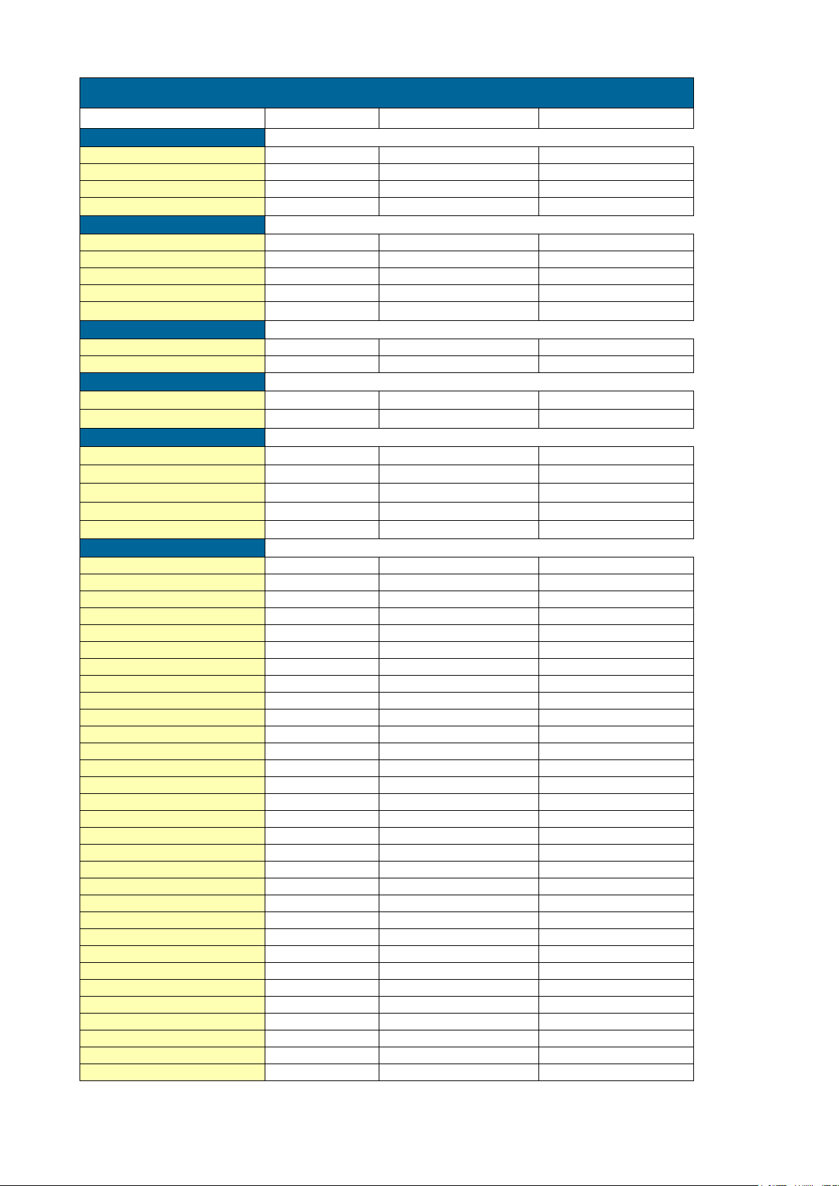
Page 46
LIST OF CONFIGURATION SETTINGS
SETTING
DEFAULT
DATE :
DATE :
1 - TOTAL
11 unit
L
12 decimals
0000000
13 span
1600
/sec
/sec
14 decs span
0
2 - FLOWRATE
21 unit
L
22 time unit
/sec
23 decimals
0000000
24 span
1600
25 decs span
0
3 - DISPLAY
31 function
total
32 light
100%
4 - POWER MANAGEMENT
41 LCD-new
1 sec
42 battmode
operational
5 - FLOWMETER
51 formula
interpolation
52 filter
1
53 cut-off
0.0%
54 calib-lo
default
55 calib-hi
default
6 - LINEARIZATION
61 percentage %
0.0%
M-Factor
1.000000
62 percentage %
0.0%
M-Factor
1.000000
63 percentage %
0.0%
M-Factor
1.000000
64 percentage %
0.0%
M-Factor
1.000000
65 percentage %
0.0%
M-Factor
1.000000
66 percentage %
0.0%
M-Factor
1.000000
67 percentage %
0.0%
M-Factor
1.000000
68 percentage %
0.0%
M-Factor
1.000000
69 percentage %
0.0%
M-Factor
1.000000
6A percentage %
0.0%
M-Factor
1.000000
6B percentage %
0.0%
M-Factor
1.000000
6C percentage %
0.0%
M-Factor
1.000000
6D percentage %
0.0%
M-Factor
1.000000
6E percentage %
0.0%
M-Factor
1.000000
6F percentage %
0.0%
M-Factor
1.000000
6G linearization
disabled
FW_F112A_v1702_02_EN
Page 47
Page 47
LIST OF CONFIGURATION SETTINGS
SETTING
DEFAULT
DATE :
DATE :
7 - ANALOG OUTPUT
71 output
disabled
72 rate-min 0
73 rate-max
99999
74 cut off
0.0%
75 tune min
160
76 tune max
6656
77 filter 1
8 - RELAY OUTPUT
81 width
0.000
82 decimals
0000000
83 amount
1000
9 - COMMUNICATION
91 speed
9600
92 address 1
93 mode
BUS-RTU
94 databits
8 bits
95 parity
none
A - OTHERS
A1 model
F112-A
F112-A
F112-A
A2 s-vers
xx.xx.xx
A3 serial nr
xxxxxxx
A4 password
0000
A5 tag-nr
0000000
FW_F112A_v1702_02_EN
Page 48

Page 48
Fluidwell B.V.
PO box 6 Voltaweg 23 Website: www.fluidwell.com
5460 AA Veghel 5466 AZ Veghel Find your nearest representative: www.fluidwell.com/representatives
the Netherlands the Netherlands © 2017 Fluidwell B.V.: FW_F112A_v1702_02_EN
FW_F112A_v1702_02_EN
 Loading...