

fluid-o-tech MG 200 Series, MG 204, MG 209, MG 213 Refurbishing Instructions
http://www.fluidotech.it
Fluid-o-Tech
Fluid-o-Tech magnet drive gear pumps MG 200 series
spare parts list and refurbishing instructions
Via Morimondo, 23
20143 Milano - Italy
Tel. (39) 02 8917071
Fax (39) 02 89170799
AF204, 8-10-17, Fukasawa,
Setagaya, Tokyo 158-0081 Japan
Tel. (81) (0) 3-3705-5440
Fax (81) (0) 3-5707-7414
161 Atwater St.,
Plantsville CT (USA) 06479
Tel. (1) (860) 276-9270
Fax (1) (860) 620-0193
1
2
3
4
15
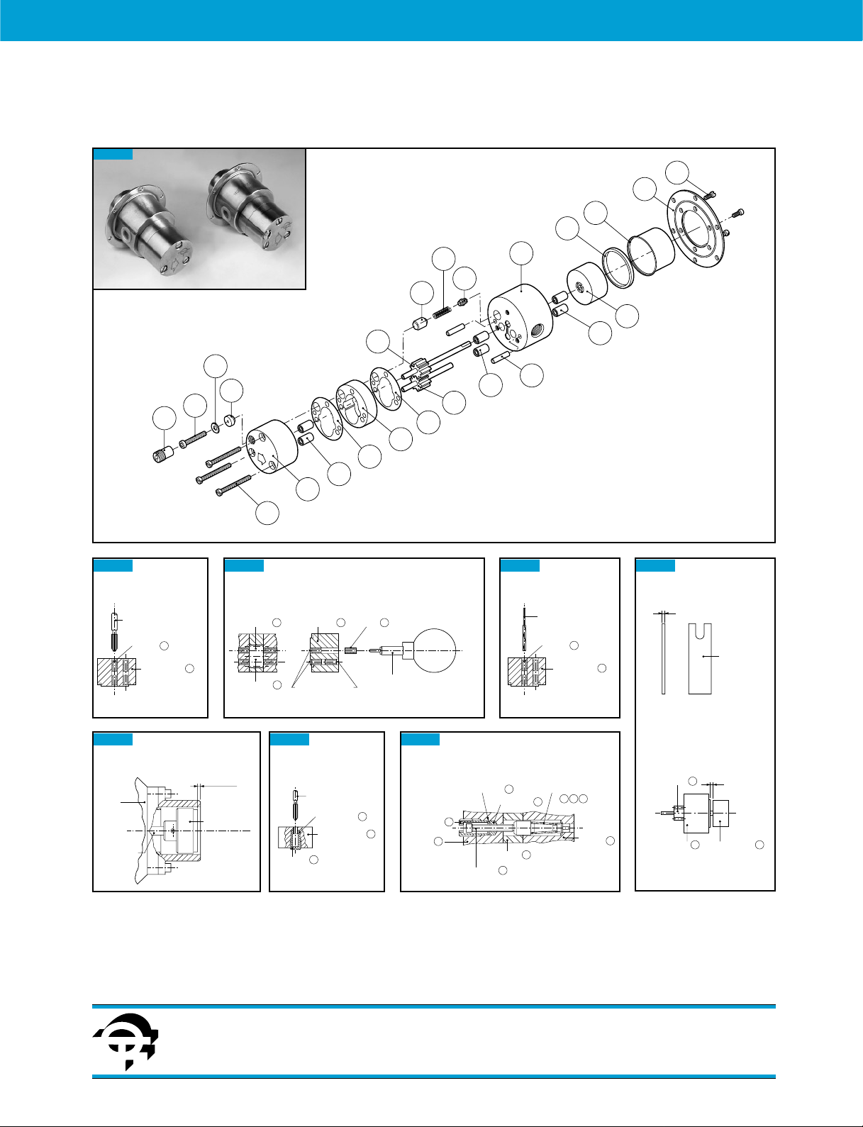
Bushings extraction
Bushing extractor tool
P/N 60211
6
Bushing
Rear housing
Figure 1
17
7
21
16
Driving gear
Driven gear
13
14
Bushings installation
8 Rear housing7Bushing
9
Recessed 0.5 mm
19
7
20
18
5
8
12
6
6
9
10
11
10
6
Driven magnet setting
A
Spacer
P/N 60213
6
Bushing tool
P/N 60212
Figure 2
Bushings reaming
Reamer
P/N 60210
6
Bushing
Rear housing
Figure 3
7
Driving magnet setting positioning
Motor
Motor shaft
By-pass seal tapping
0
3-0.1 mm
Driving magnet
By-pass nut
Figure 7
Tap P/N 60214
By-pass seal
Front housing
15
Figure 6
16
By-pass nut
13
Front
13
housing
By-pass
21
By-pass seal
15
Housing
11
Adjusting screw
17
Figure 4
7
Driving gear 8
Rear housing 7
Poppet assemblyBy-pass washer
20
18
19
16
Rear
housing
Figure 5
A
Driven magnet 5
Disassembly Instructions
Provide a clean surface for work area.
Separate the pumphead from the magnet cap.
Remove the 3 screws and disassemble front housing ,
driven gear , central housing and dowel pins .
If the pump is equipped with by-pass, make sure not
to damage the sealing poppet .
Remove the poppet assembly from the adjusting screw
(fig. 5),remove the by-pass nut , the adjusting screw
turning counter-clockwise,the by-pass washer and
the by pass seal from the cap.
Remove the screws which secure the magnet cup
and the mounting plate to the rear housing and
disassemble.
Remove and discard all the bushings from the rear
housing and the front housing with the bushing
extractor tool P/N 60211 (fig.1).
Remove seal and flat seals from the rear housing
and from the front housing and discard them.
If wear on front housing, rear housing or center housing
is excessive, rebuilding the pump my not be advisable.
Re-Assembly Instructions
Clean carefully all parts before re-assembling.
Any foreign body material clinging to magnet must
be removed.
Note
Bushings - Bushings on both sides of gears must be
recessed 0.5 mm from the face of the rear housing
and front housing (fig. 2)
Bushings Installation - Press 6 new bushings into
the rear housing and front housing as shown
in figure 2 using P/N 60212 installation tool.
Once in place, the bushings need to be reamed with
P/N 60210 reamer tool (fig. 3).
Seals - Apply a thin coat of silicone grease on the central
housing surfaces and place the flat seals on each
side of it insert the driving gear into the rear housing
and then insert the shaft of the driving gear in the
driven magnet using the spacer P/N 60213 (fig. 4).
Insert 2 dowel pins in the body.
Slip carefully central housing onto dowel pins against
body face, verifying the proper,alignment of the screw
holes.
Install the driven gear (The side of gear assembly
with longer shaft extension goes into the rear housing).
If pump is equipped with by-pass, install the by-pass
seal , then by-pass nut and tighten to prevent
by-pass seal rotation.
Then tap the by-pass seal with the P/N 60214 tool (fig. 6).
Disassemble the by-pass nut and install by-pass washer
and turn clockwise the adjusting screw before
installing again the by-pass nut tightening.
Align the cap bushing holes with gear shafts, and dowel
pins with cap dowel pin holes and assemble.
Make sure that the poppet assy goes fully into poppet
holes and seat (fig. 5).
Install 3 screws in cap and tighten alternately
as tight as possible.
Turn driven magnet with fingers to check for any
binding during the rotation: the magnet should turn
freely.
Install magnet cup and mounting plate with
3 screws and turn alternately until tight.
Assemble the driving magnet to the motor (see fig. 7)
and the pumphead to the motor.
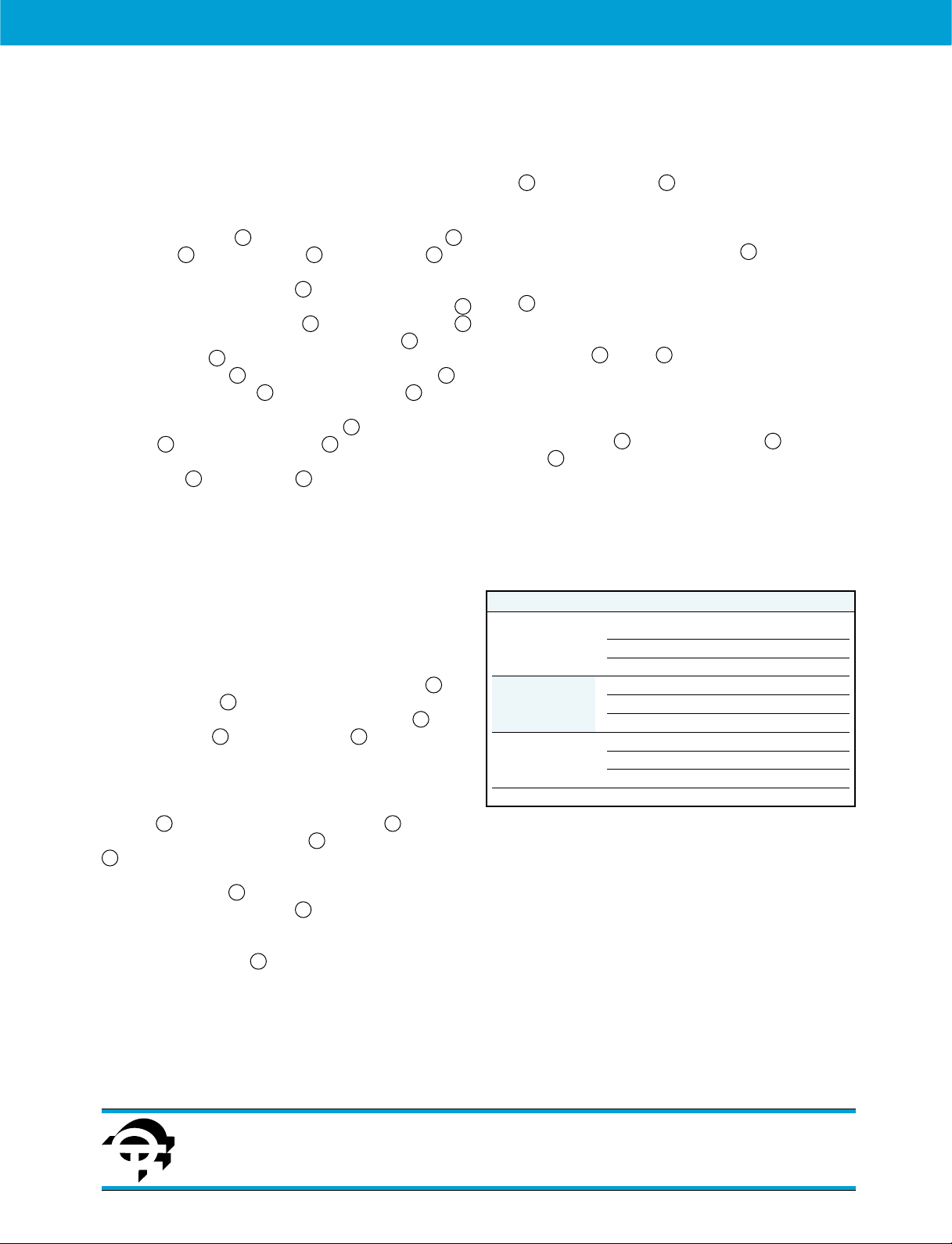
Service Kit - MG Gear Pump
Stainless steel pumphead
Service kit contents
2 gears - 1 Teflon “O” ring - 2 Teflon flat seals - 6 bearings
Service kit tools
1 reamer P/N 60210
1 extractor P/N 60211
1 bushing tool P/N 60212
1 spacer P/N 60213
1 tap P/N 60214
SPARES & INSTRUCTIONS – 10/01 Ed.
Fluid-o-Tech magnet drive gear pumps MG 200 series
spare parts list and refurbishing instructions
14
9 11
11 10
8
7
12
11
9
20
15
16
1 3
72
6
7
4 10
13
13
6
7 13
7
21
17
17
12
13
16
12
14 13
3
1
2
15
17
Gear material Service Kit P/N
PTFE MGKT3
204 pumphead RYTON
®
MGKR3
PEEK
™
MGKP3
PTFE MGKT4
209 pumphead RYTON
®
MGKR4
PEEK
™
MGKP4
PTFE MGKT5
213 pumphead RYTON
®
MGKR5
PEEK
™
MGKP5
http://www.fluidotech.it
Fluid-o-Tech
Via Morimondo, 23
20143 Milano - Italy
Tel. (39) 02 8917071
Fax (39) 02 89170799
AF204, 8-10-17, Fukasawa,
Setagaya, Tokyo 158-0081 Japan
Tel. (81) (0) 3-3705-5440
Fax (81) (0) 3-5707-7414
161 Atwater St.,
Plantsville CT (USA) 06479
Tel. (1) (860) 276-9270
Fax (1) (860) 620-0193
 Loading...