

fluid-o-tech DGD Series, DGM Series Instruction Manual
CALL TOLL FREE 877-742-2878 FOR SALES AND SUPPORT
Return to BurtProcess.com
INSTRUCTION
MANUAL
VECTRA GEAR PUMPS DGD AND DGM SERIES
INSTALLATION
Please read the following instructions before conducting a
new installation. The pumps of the DGD series are direct-drive
pumps, while those of the DGM series are magnetic-drive
pumps. The DGD and DGM units must be handled only by
specialised personnel who have the basic technical knowledge
related to hydraulic and electromechanical installations.
WARNINGS
The gear pum ps pa rt of the DG D and DGM serie s are
normally ass emb led with non -pr otected mot ors in cas e
of “locked rotor”. This is why we recommend inserting a
fuse and adequately sized components in the power supply
circuit to withstand this condition. Inadequate circuits and/or
components may overheat, causing damage and/or a fire.
Before connecting the motor is necessary to check the
polarity is correct. During installation be careful not to reverse
the polarity, in which case the pump would rotate in the
opposite direction and for some motors this could cause
permanent damage to the unit itself.
For the DGM version, the flange must be
handled carefully.
Do not handle it with tongs or vice that could
lead to a misalignment of the magnets and a
decline in the pump’s performance. In case
of continuous operation, the unit must be
installed in a ventilated
space to dissipate the heat generated by the motor.
In order to avoid noise and vibration of mechanical parts,
we recommend installing the unit with rubber anti-vibration
mounts. Take special care when connecting the pump to
the fittings in order to avoid potential leaks. The pipe holders
integrated in the DGD and DGM pumps are designed to be
coupled with silicone pipes (60ShA) with an internal diameter
measuring 6 mm and 1.5 mm thick.
Other types of pipe could damage the pump. The unit’s
pipe holders are not designed to withstand any mechanical
load. We recommend fastening at least the delivery pipe with
a plastic strap. We recommend removing the two plastic
plugs located in the pump’s intake and delivery ducts just
before mounting the fittings and pipes to prevent solid foreign
obje cts from ent ering insid e, as they could damage the
internal components of the pump.
Do not use liquid sealant, as drops could fall in the ducts and
cause the pump to block.
For use in the food industry, the pumps (even if NSF-certified)
must first be sterilised by circulating water inside them at
a temperature of 80 °C/176 F for at least 20 minutes. The
water used for this operation must not be reused during the
sterilisation or thereafter, but must be flushed away. If the unit
is replaced, it is necessary to ensure that the model matches
the one being replaced. Change the unit with one with a
different flow rate could damage the system. The circuit must
be thoroughly cleaned and rinsed before starting up the unit.
MANUAL - DGD/DGM en. - 06/13 Ed.
Fluid-o-Tech reserves the right to alter the specifications indicated in this catalogue at any time and without prior notice.
Fluid-o-Tech srl
Via Leonardo da Vinci, 40
20094 Corsico, Milano, Italy
Tel. +39 02 9995 01
Fax +39 02 9995 0999
info@fluidotech.it
Fluid-o-Tech Int’l Inc.
161 Atwater St.,
Plantsville CT (USA) 06479
Tel. +1 (860) 276 9270
Fax +1 (860) 620 0193
info@fluid-o-tech.com
Fluid-o-Tech Int’l Inc. Japan
203, 2-17-19, Ebara, Shinagawa
Tokyo 142-0063, Japan
Tel. +81 (0) (3) 3783 9660
Fax +81 (0) (3) 3783 9661
k.kato@fluidotech.com
Fluid-o-Tech Asia (Beijing) Co., Ltd
Jingwei Industrial Zone,
Beifang Huairou, Beijing, 101400, PRC
Tel. +86 (0) (10) 6168 4650
Fax +86 (0) (10) 6168 4651
info@fluidotech-asia.com
GENERAL SAFETY ADVICE
1 The DGD and DGM pumps are often powered by DC motors
with brushes, a known source of ignition. Do not use these
motors in potentially explosive atmospheres.
2 After prolonged use or applications with hot fluids, the surfaces
of the pump and the motor could be hot and potentially cause
injury to skin or burns. After disconnecting the power supply,
wait for the pump to cool down before touching it.
3 Do not place the pump near materials with low auto-ignition
temperature/flammable materials. The outer surfaces of the
unit can reach high temperatures. Install the pump in a dry area
protected from dust, splashes and condensation.
4.
Often motors are cooled by natural convection. We recommend
installing the unit in areas where maximum and adequate
ventilation is ensured. As an indication, the minimum distance
from the walls around the unit should be at least 50 mm. Do not
wrap the unit with insulation material and do not install it near hot
surfaces. Do not use the pump in environments or with fluids at
temperatures higher than those reported in the catalogue.
Check the compatibility with the fluid used beforehand. Do not
5
use or allow the pump to come in contact with chemicals that
could damage the unit.
An inadequate circuit could cause excessive pressure or
6
overheating. Make sure the unit is used in accordance with to
the curves in the catalogue.
Install the hydraulic circuit with adequate safety margins, both in
terms of pressure and temperature.
www.fluidotech.com
We recommend a minimum safety factor of 1.5. Protect the
DGM and DGD units from frost. Freezing could permanently
damage the pump and pipes.
7 The DGD and DGM units are low voltage devices, though it is
still necessary to comply with the relevant safety standards.
The installer is responsible for making sure current regulations,
closely associated with the final application, are complied with.
8 Insert a filter of a suitable size upstream of the pump to prevent
solid particles with a diameter greater than 10μm from entering
inside. The surface of the filter must be sized in relation to the
flow rate and type of circuit in order to prevent excessive drops
in pressure. This filter must be cleaned periodically.
9 If the units are connected in circuits fitted with solenoid valves,
make sure these always act with a certain delay after the motor
shuts down. Solenoid valves with early or simultaneous closure
can cause excessive pressure or cavitation and damage the
unit and/or the hydraulic circuit.
10 We recommend inserting a fuse of a suitable size in the unit’s
power supply circuit to avoid damage to the unit and/or
electrical circuit.
11 Make sure the electrical connections can ensure the necessary
seal and insulation. Inadequate connections could cause damage.
12 Choose your DGD or DGM unit model in relation to the
application cycle and performance required.
Using the units in harsher conditions than the ones they were
designed for could cause damage. Use the unit only for the
time required for the application.
PLAN THE INSTALLATION
1 Make sure the size of the electrical circuit and hydraulic circuit
is suited to the electrical and hydraulic features of the DGD and
DGM units. Provide adequate identification for the sections of
the hydraulic and electric circuit.
2 The installation must be conducted in a well ventilated, dry
area protected from splashes, away from heat sources and
flammable fluids. Install the pump in an accessible place to
make subsequent maintenance work easier. Place the unit in a
horizontal position or with the pump facing downwards.
3 Make sure the unit is not subjected to vibration induced by the
mechanical or hydraulic connection. If such a condition occurs,
insulate the unit with adequate anti-vibration mounts.
4 Provide for requirements related to the pre-assembly/mounting
of the unit’s accessories, such as the installation of the motor
unit of the DGM pump (see relevant paragraph)
5 Provide for the cabling requirements of any additional electronic
boards. If the boards are fitted with heat sinks, install them
adequately to favour dissipation through natural convection.
INSTALLATION
1 Se cure t he un it fro m a me c hani cal po int of view . We
recommend installing it horizontally (with the motor axis parallel
to the ground) or, in the event of vertical installation, with the
pump facing downwards. Secure the pump to the motor using
the designated adapter (only for DGM units).
2 Remove any IN/OUT protective plugs on the ducts.
3 Connect the unit to the hydraulic and electrical circuit.
Make sure it does not cause mechanical stress and pay special
attention to the fluid there may be in the pipes, as this must
not come into contact with electrical parts. In case of negative
suction head, prime the unit. The electrical, hydraulic and
mechanical connections must be able to ensure the necessary
seal during operation of the unit.
4 Make sure the polarity and voltage in the electric circuit near
the connection to the motor matches the data reported on the
unit’s plate. Identify the positive pole, which should preferably
be protected by a fuse. Please remember that reversing the
polarity may cause permanent damage to the unit. With the
electrical circuit not powered on, connect the motor.
5 Make sure the unit is able to prime the fluid. If this does not
happen after 15 seconds, check the efficiency of the intake
circuit’s seal. Make sure there are no leaks in the hydraulic
circuit in both the delivery and in the intake section.
6 Check the operation of the valves, which must be fully open
when the unit is installed. Gradually close the delivery valve until
the required performance is achieved. Finally, make sure the
hydraulic performance and absorption values are consistent
with the ones the machine was designed for.
7 Once the pump has been primed, check if it is operating
correctly. The parameters to verify this are: the rotation speed
of the motor, the flow rate and pressure in relation to the power
absorbed. Make sure there are no air bubbles in the delivery/
intake duct. Air bubbles could be caused by cavitation or poor
seal of the pipe connected to the intake duct.
CONNECTING THE MOTOR TO THE MAINS
The electrical features of the mains must be compatible with the
electrical data on the motor’s plate, particularly the supply voltage
and frequency. The motor must not be connected to the mains
during installation.
CHOOSING THE MOTOR (DGM ONLY)
If the motor is not supplied with the pump, make sure the coupling
dimensions and relative tolerances are those recommended by
Fluid-o-Tech. The flow rate is proportional to the speed of the
motor. The maximum continuous torque must be less than 0.1 Nm
with an external and internal magnetic joint made of ferrite
ASSEMBLY OF THE DRIVE SHAFTS’
MAGNET (DGM ONLY)
Motors with smooth shafts (“D” type)
1. To make sure there are no imperfections in the thread which
might prevent the dowel from blocking the magnet on the drive
shaft, screw the dowel on the threaded hole of the magnet
holder until it protrudes from the hole of the metal insert.
2. Unscrew the dowel until the hole where the shaft will be placed
is completely clear.
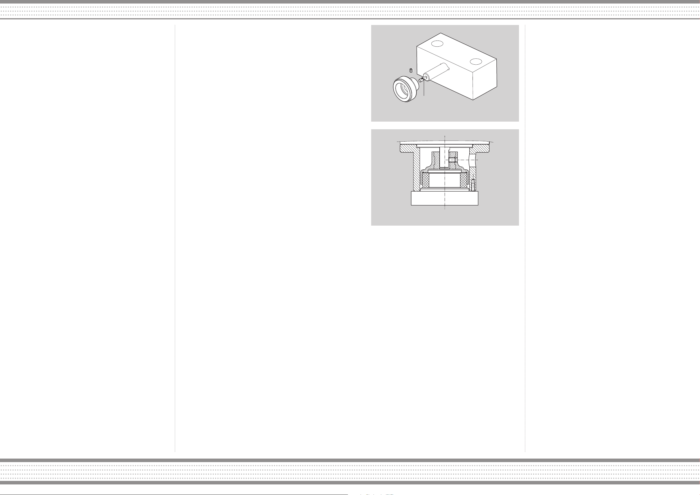
3. Place the magnet on the AT152 device with the fixing dowel
placed on the reference surface of the “D” pin (fig. 1).
4. Screw in the dowel until it touches the surface of the pin to
allow for an easy extraction of the magnet. The surface of the
equipment’s pin must not be scratched by the dowel when the
shaft is removed.
5. Remove the magnet and place it on the drive shaft. In these
conditions, the magnet’s dowel protrudes by a few tenths beyond
the inner diameter of the hole of the brass bushing and prevents
the magnet from being positioned incorrectly on the drive shaft.
6. Place the motor vertically on the AT152/1 device with the
magnet facing downwards in order to place the magnet in the
correct position (fig. 2). Tighten the dowel to the maximum
torque of 1.5 Nm. MGAF series external magnets with “D” shaft.
Tool pin reference plane
Fig. 1 - Reference surface for the pin device
AT 152/1
Fig. 2 -MGAF series external magnets with “D” shaft
OPERATING CONDITIONS
Make sure the pumped fluid is compatible with the materials of the
pump. Fluid-o-Tech’s gear pumps are designed to work only with
clean fluids and are tested with water at ambient temperature.
Any other fluid and/or operating condition must be verified and
approved by the end customer under the actual conditions of
use. Make sure the maximum temperature of the liquid and the
environment are compatible with the model used. It is necessary
to use – especially on the pump’s intake duct – pipes with an inner
diameter adequately sized in relation to the pump’s flow rate. This
precaution prevents the risk of cavitation and resulting damage on
the pump.
The sum of the inlet and outlet pressure must not exceed the
maximum system pressure indicated in the catalogue.
We recommend you adapt the size of the pipe in relation to the
delivery duct for pressure values at least 1.5 times the maximum
pressure of the system.
The pumped fluids must not contain solid suspended particles.
Before mounting the pump, we recommend installing a 10 µm
filter with a surface area large enough in order to prevent excessive
pressure drops in the circuit. Although occasional, particles larger
than 10 µm cause premature wear of internal components. It is
also important to periodically check the state of the cartridge and
the filter. To monitor the filter we recommend installing a pressurevacuum gauge after the filter. If the vacuum increases by more than
0.1 bar, the cartridge must be cleaned or replaced.
Although DGD and DGM gear pumps are self-priming pumps, they
should operate with a positive suction head. Indeed dry running
causes premature wear of the internal components of the pump.
If the water supply system operates with low pressure or no flow
rate, it is necessary to install a pressure switch before the pump to
turn off the motor. It is also necessary also protect the system from
accidental excessive pressure with safety devices such as a bypass
valve or a pressure switch connected to the motor.
The solenoid valves must not be installed in the circuit but, if
necessary, must only be installed on the delivery section of the
pump. We strongly recommend against installing the solenoid valves
before the pump. To avoid pressure peaks it is necessary to close
the solenoid valve only after the pump has stopped, then wait a
few seconds after the motor has been turned off to allow it stop
completely. The size of the inner diameter of the solenoid valve’s
duct must be adequate to the pump’s flow rate. The maximum
pressure depends on the unit model used.
Outside the values specified in the charts on page 4 the unit could
stop or the coupling could fail (DGM only). To re-fit the coupling it
is necessary to disconnect the motor’s power supply and wait till it
stops before restarting it.
STANDARD MAINTENANCE
Ma inte nanc e an d replace ment of part s su bjec t to wear of
Flu i d - o - T e c h’s DGD a n d DGM u n i ts must b e perfor m e d
by qu a l if i e d tec h n ic a l st aff . W e rec o m me n d cl ea n i ng
the circ u i t a n d fi l t e r s p eriodically t o p r e v ent cavita t i o n
an d wea r of th e int e rn a l co m po n e n t s of t h e pu m p .
WARRANTY TERMS AND CONDITIONS
Every pump comes with a 12-month warranty valid from the date
of manufacture indicated on the label, plus a period of 3 months to
cover transport and storage. This period shall not exceed 15 months
from the date of the original invoice under any circumstances.
Fluid-o-Tech can only for held liable for the repair or replacement of
faulty parts returned on a DDP base, provided that our inspection
reveals that the part(s) in question was faulty at the time of sale.
The warranty is voided if:
• Themounting/useinstructionshavebeendisregarded.
• The pump was removed by a technician not authorized by
Fluid-o-Tech and/or repaired with non-original parts.
• Thepumpoperatedwithnowaterorundercavitationconditions.
• Solidforeignparticlesarefoundinthepump.
• Clearsignsofexcessivepressurearedetected.
• The pump hasbeenusedforanapplication it was not intended
for, where the operating conditions and/or the pumped liquid are
incompatible with the pump itself and therefore such application
had not been approved by Fluid-o-Tech.
• Thewarrantydoesnotcoverthenormalwearofthepump.
The repair or replacement of faulty parts during the warranty period
will not extend the original period of the warranty.
CERTIFICATIONS
Some gear pump models of the DGD and DGM series are NSF
certified for use with food-grade fluids. The CE label can be applied
only on motor-pump units. The label cannot be applied on the pump
alone in accordance with the applicable EC standard.
In this case the group meets the requirements of the following
directives: 89/366/EEC concerning Electromagnetic Compatibility
– EMC, 73/23/EEC concerning electrical equipment for use in
po tenti ally explo sive a tmos phere s – DT B and 9 4/9/ E C on
Equipment and Safety devices intended for use in potentially
explosive atmospheres – ATEX. Fluid-o-Tech is able to provide
a declaration of conformity to certify compliance with the above
mentioned Directives.
 Loading...