

Page 1

Fluidmesh 1100/1200VOLO/3100 MITO series
User manual
Firmware Version 6.0.×
Fluidmesh 1100/1200VOLO/3100 MITO Series
Copyright © 2005-2013 Fluidmesh Networks LLC.
Page 2

Page 3

WARNING
ONLY QUALIFIED PERSONNEL SHOULD INSTALL THIS UNIT. THE INSTALLATION SHOULD CONFORM TO ALL LOCAL CODES. IN SOME
COUNTRIES, A CERTIFIED ELECTRICIAN MAY BE REQUIRED.
CAUTION
When open, the apparatus should not be dripping or splashing. No object
filled with liquid shall be placed on the apparatus.
NOTICE TO USERS
Copyright © Fluidmesh Networks LLC. All rights reserved. This manual
or the software described herein, in whole or in part, shall not be
reproduced, translated or reduced to any machine-readable form without
prior written approval from Fluidmesh Networks LLC.
FLUIDMESH NETWORKS LLC, PROVIDES NO WARRANTY WITH REGARD TO THIS MANUAL, THE SOFTWARE OR OTHER INFORMATION
CONTAINED HEREIN AND HEREBY EXPRESSLY DISCLAIMS ANY IMPLIED WARRANTIES OF MERCHANTABILITY OR FITNESS FOR ANY
PARTICULAR PURPOSE WITH REGARD TO THIS MANUAL, THE SOFTWARE OR SUCH OTHER INFORMATION. IN NO EVENT SHALL FLUIDMESH NETWORKS, INC. BE LIABLE FOR ANY INCIDENTAL, CONSEQUENTIAL OR SPECIAL DAMAGES, WHETHER BASED ON TORT,
CONTRACT, OR OTHERWISE, ARISING OUT
WITH THIS MANUAL, THE SOFTWARE OR OTHER INFORMATION CONTAINED HEREIN OR THE USE THEREOF.
OF OR IN CONNECTION
Fluidmesh Networks LLC, reserves the right to make any modification to
this manual or the information contained herein at any time without notice.
The software described herein may also be governed by the terms of a
separate user license agreement.
Fluidmesh is a registered trademark of Fluidmesh Networks LLC, MeshWizard, EasyMesh, FMQuadro, FluidThrottle, Endo, MITO are trademarks
of Fluidmesh Networks, Inc.
Microsoft, Windows, Internet Explorer are registered trademarks of Microsoft Corporation in the United States and/or other countries.
1
Page 4

Ethernet is a registered trademark of Xerox Corporation.
All other brands and product names are trademarks or registered trademarks of their respective owners.
2
Page 5

Contents
1 Manual Overview 6
2 Precautions 7
3 Installation and System Set-up 8
3.1 Fluidmesh 1100 MITO Series .... .... ......... . 8
3.1.1 Proper Installation Procedures . .... ... .... . 9
3.1.2 Powering on an FM1100 . . . ... . . .... .... . 9
3.1.3 Status and Link LEDs . . . .... . . ... . . .... 10
3.1.4 Factory Default Hardware Reset ... ... .... . . 10
3.1.5 Integrated Panel Antenna . . ... .... . . . . ... 11
3.2 Fluidmesh 3100 MITO Series . . . . .... ......... . 12
3.2.1 Proper Installation Procedures . .... ... .... . 13
3.2.2 Powering on an FM3100 . . . ... . . .... .... . 13
3.2.3 Status and Link LEDs . . . .... . . ... . . .... 14
3.2.4 Factory Default Hardware Reset ... ... .... . . 14
3.2.5 Integrated Panel Antenna . . ... .... . . . . ... 15
3.3 Fluidmesh 1200VOLO
3.3.1 Proper Installation Procedures . . . . . . . . . . . . .
3.3.2 Powering on an 1200 VOLO. . .. . . . . . . . . . . . .
3.3.3 Status and Link LEDs . . . . . . . . . . . . . . . . . .
3.3.4 Factory Default Hardware Reset . . . . . . . . . . . .
3.3.5 Integrated Panel Antenna . . . . . . . . . . . . . . . . 19
4 Fluidmesh Architecture Overview 20
4.1 Point-to-Point Wireless Bridge ..... ... . . . . . . .... 20
.. . . .
. . . . . . . . . . . . . . . .
16
17
17
18
18
4.2 Mesh Network Architecture ........ .... . . ... . . 21
4.3 Point-to-Multipoint Architecture: FluidMAX™ . . . . ..... 22
3
Page 6

5 Fluidmesh Network Addressing 24
5.1 Bridge IP Addressing . . . .... . . ... .... . . . . ... 24
5.1.1 Connecting and Configuring IP Devices and Cameras 25
5.2 Mesh Addressing . . . ... ........ . . ..... .... 25
5.2.1 Network Addressing . . . ... ....... . . . . . . 26
6 Software Plug-ins 29
6.1 Plug-in Activation/Deactivation Procedure . .... . . . . . . 30
7 Web-based Interface and Configuration 33
7.1 Software and Hardware Requirements .... . . ..... . . 33
7.2 Logging-in to the Web-based Interface ... .... . . . . . . 34
7.3 End-user License Agreement and Region of Operation . . . . 35
7.4 MeshWizard™ . . . ... ....... .... .... ..... 37
7.5 Web-based Interface Menus ........ .... . . ... . . 37
7.6 General Mode ... ... . ...... .... .... . . ... 38
7.7 Wireless Settings ... ..... ...... ... . . . . . . . . 38
7.8 Advanced Wireless Settings . ...... . . ..... . . ... 42
7.9 Antenna Alignment Tools and Physical Statistics ... .... 43
7.10 Frequency Scan Tool ... . . ......... .... . . . . . 45
7.11 FMQuadro™ (Mesh End only) ..... .... ..... . . . 47
7.11.1 VLA
N Tagging Configuration (Software Plug-in Re-
quired) .... . . . ....... .... . . .... ... 53
7.12 Firmware Upgrade . . ... . ...... ... ...... . . . 54
7.13 Plug-in Management . . .... ..... ... ... ...... 56
7.14 Advanced Tools . . . . . ..... . . . . .... ....... . 57
7.15 Multicast . . ... . ..... ... . ... . ........ ... 58
7.16 PoE Passthrough (FM1100 and
FM1200 only) . . . . . . . . . 59
7.17 Change Password ... . .... . . ....... ... ... . 59
7.18 Status ... ..... . ... ......... ..... ... . . 59
7.19 Reboot and Reset to Factory Default . . . . .... ... ... 60
7.20 On-line Help ....... ......... . .... ... ... 60
4
Page 7

8 Troubleshooting 61
8.1 I am unable to get the log-in screen . . .... ... . . . . . 61
8.2 I am unable to log-in into the Web-based interface .... . . 61
8.3 I forgot the administrator password .... ... ...... . . 62
8.4 In Bridge Mode I get no Link or the Link LED is always red or
I am getting a weak Wireless link (below 60% signal strength) 62
5
Page 8
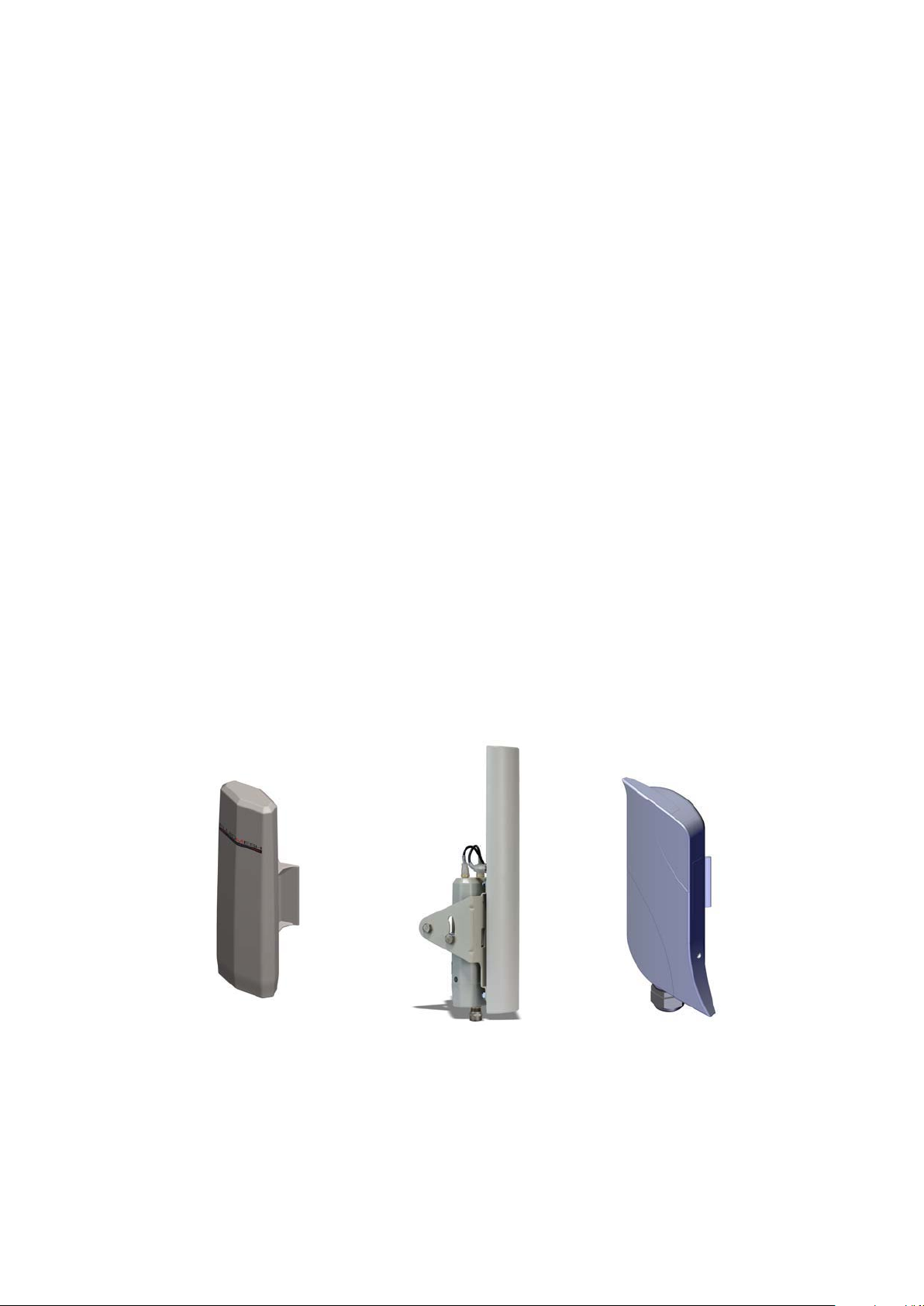
1 Manual Overview
This manual describes how to install and operate the Fluidmesh VOLO
and MITO series products. More specifically, this manual contains a
general overview of the Fluidmesh 1100 MITO,
the Fluidmesh 3100 MITO in Section 3.1, Section 3.2
respectively. Please refer to Fig. 1.1(a), Fig. 1.1(b) and Fig.1.1(c) for a
representation of each product. This user’s manual also includes a
complete overview of the network architectures that can be created using
Fluidmesh technology, and is discussed in Section 4. The Fluidmesh network addressing is described in Section 5. The use of Fluidmesh software
plug-ins, their features, and their installation procedures in a network follows in Section 6. The Web-based Graphical User Interface (GUI) is then
described in Section 7. Please note that, unless otherwise explicitly specified, the Web GUI presentation refers to the Fluidmesh 1100,
1200 and the Fluidmesh 3100. Screenshots shown in this manual are
explanatory examples and may be different from the ones that appear
when you run the Web-based configuration software.
Fluidmesh 1200 VOLO and
and Section 3.3
Fluidemesh
(a) Fluidmesh 1100 MITO (b) Fluidmesh 3100 MITO
Figure 1.1: Fluidmesh 1100 MITO, Fluidmesh 1200 VOLO and Fluidmesh 3100 MITO front view.
6
(c) Fluidmesh 1200 VOLO
Page 9

2 Precautions
Fluidmesh Networks products are for professional use only.
Fluidmesh Networks products have been designed with safety in mind.
However, if not used properly, they can cause fires which may lead to
serious bodily injuries. To avoid such accidents, make sure that you are
properly qualified to install these products.
In Case of Breakdown
In case of system breakdown, discontinue use and immediately contact
your authorized Fluidmesh Networks dealer or Fluidmesh Networks LLC.
directly.
In Case of Abnormal Operations
If the unit emits smoke or an unusual smell, if water or other foreign matter enters the enclosure, or if your drop the unit or damage the enclosure,
power off the unit immediately and contact your authorized Fluidmesh Networks dealer or Fluidmesh Networks LLC directly.
7
Page 10
3 Installation and System
Set-up
This section describes how to install and set up Fluidmesh products. Specifically, the Fluidmesh 1100 MITO,
3100 MITO series are described in Section 3.1, Section 3.2
respectively.
3.1 Fluidmesh 1100 MITO Series
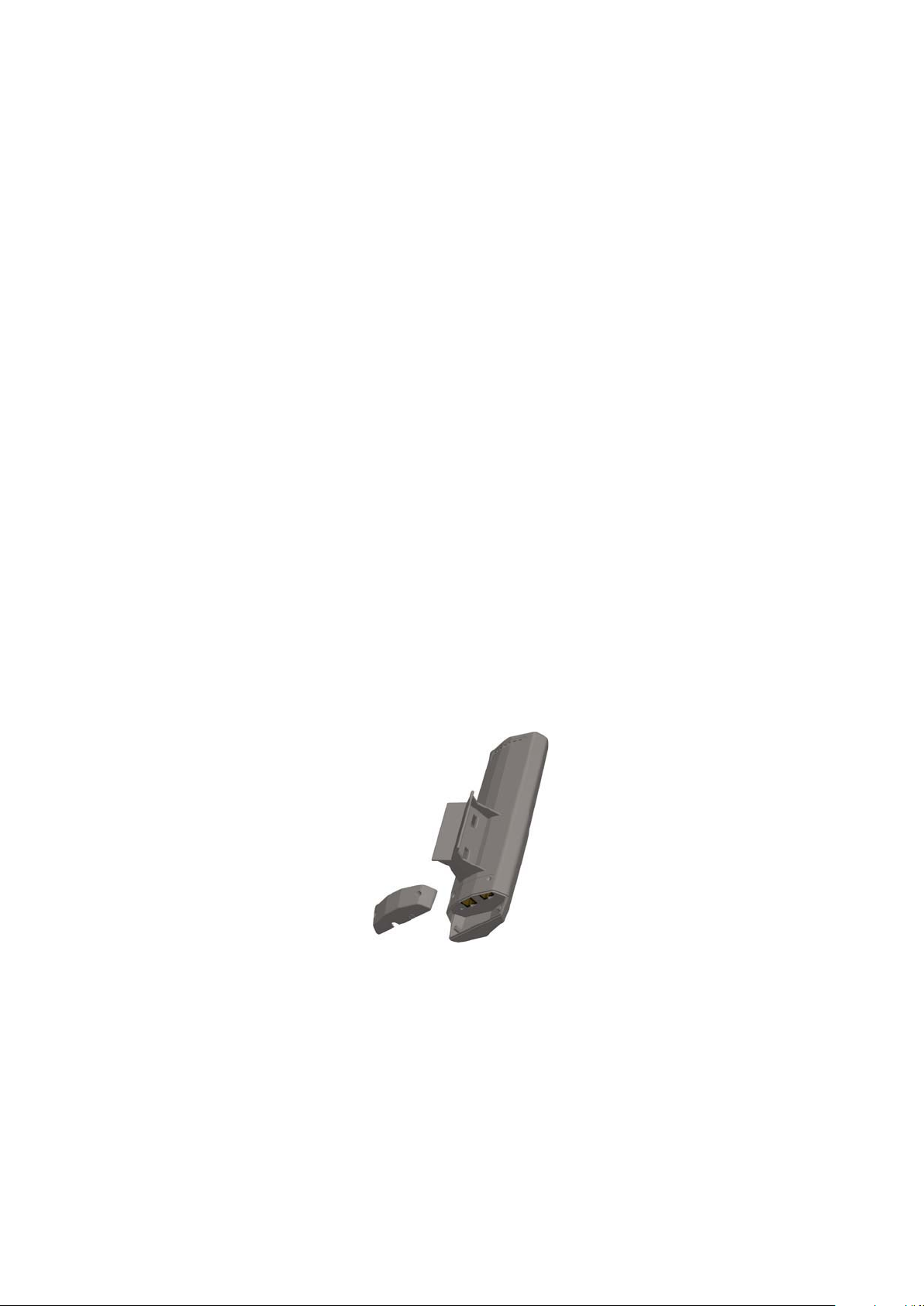
The Fluidmesh 1100 MITO (part number FM1100M-HW, for simplicity referred to as FM1100) is designed for wireless operations .
The hardware is multi-band panel an-tenna which can be mounted and
oriented using the supplied pole-mounting adapter as depicted in Fig.
3.1 and Fig. 3.2
Fluidmesh 1200 VOLO and Fluidmesh
and Section 3.3
Figure 3.1: Fluidmesh 1100 enclosure (back).
The FM1100 can operate both as a point-to-point wireless bridge or as
a single radio mesh unit. The former operating mode is described in Section 4.1 whereas the latter is discussed in Section 4.2.
8
Page 11
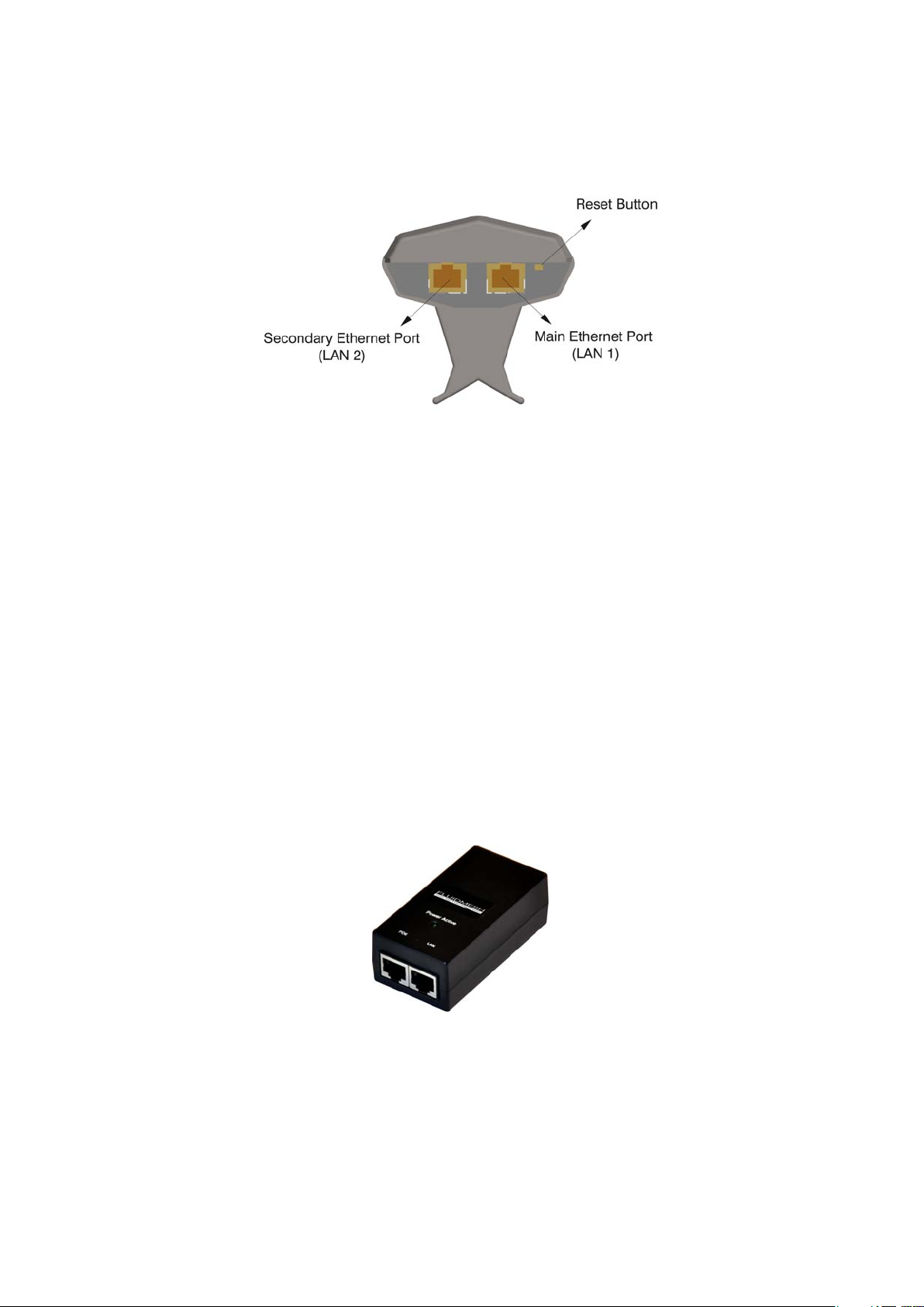
Figure 3.2: Fluidmesh 1100 pole mounting adapter, Ethernet ports and
reset button.
3.1.1 Proper Installation Procedures
The FM1100 comes with a pole-mounting adapter, shown in Fig. 3.2, that
allows the installer to change the alignment of the antenna along the horizontal axis. Plastic or metal tie wraps can be used to install the unit on a
pole.
3.1.2 Powering on an FM1100
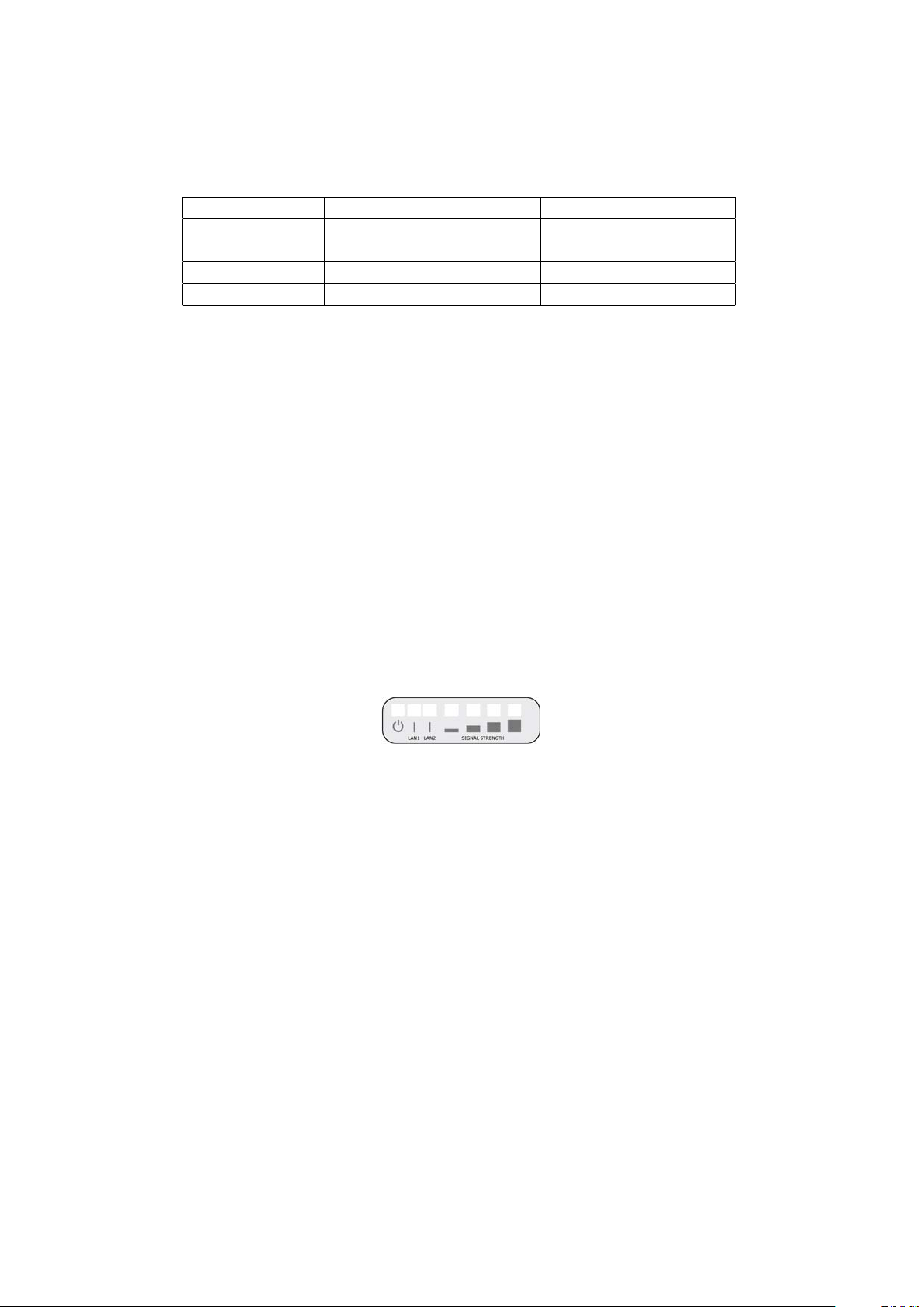
The unit can be powered only with the Power-over-Ethernet injector provided with the FM1100 (Fig. 3.3). The PoE injector does not comply with
the 802.3af standard and therefore it cannot be substituted with a different
injector.
Figure 3.3: Fluidmesh 1100 Power-over-Ethernet injector.
The PoE injector must be powered 100-240V 50-60Hz AC using the AC
9
Page 12
LED # (Color) Boot Status Link Quality
1 (Red) Booting core system poor/link absent
2 (Orange) Booting wireless system fair
3 (Green) Booting routing engine good
4 (Green) Booting unit configuration very good
Table 3.1: FM1100 Boot/Link Status LEDs Color Scheme
adapter included.
3.1.3 Status and Link LEDs
A panel on the back of the FM1100, shown in Fig. 3.4, provides seven
(7) LEDs which can be used to check the unit and the link quality status.
From the left-hand side, the first 3 green LEDs indicate the unit power, the
Ethernet port #1 activity and the Ethernet port #2 activity, respectively. The
remaining 4 colored LEDs indicate the level of the link signal and can be
used for antenna alignment purposes. During the unit boot-up process,
the 4 colored LEDs indicate the boot status and can be used for problem
detection. In fact, the LEDs light up in sequence from the leftmost one (red)
to rightmost one (bright green). If the LEDs lighting up sequence does
not complete, then an error has been detected during the booting process.
Please refer to Table 3.1 for details.
Figure 3.4: From left to right status LEDs, link/boot LEDs.
3.1.4 Factory Default Hardware Reset
The FM1100 can be reset to factory default using the RESET button placed
nearby the Ethernet ports as shown in Fig. 3.2. To reset the FM1100 to
factory default settings, power up the unit and wait approximately 40 seconds for the unit to boot up. Once the unit is up and running, press the
reset button for 5 seconds. The FM1100 will restore the factory default settings and automatically reboot. After the reset, the default IP address of
192.168.0.10/255.255.255.0 is restored and the administrator password is
set to admin.
The RESET button can also be used to reboot the unit when pressed for 1
second.
10
Page 13

3.1.5 Integrated Panel Antenna
The FM1100 has an integrated panel antenna that can operate at 4.9-6.0
GHz. A separate or external antenna cannot be installed or mounted. The
gain of the antenna is 15 dBi at 4.9-6.0 GHz. The specifications of the
integrated panel antenna are reported Table 3.2.
Gain at 4.9-6.0 GHz 14.6-16.1 dBi
Frequency Range 4940-6075 MHz
Polarization Dual Linear
3 dB Beam Angle @ 5470 MHz 43 degrees
Front to Back Ratio 22 dB
Table 3.2: Antenna Specifications
11
Page 14
3.2 Fluidmesh 3100 MITO Series
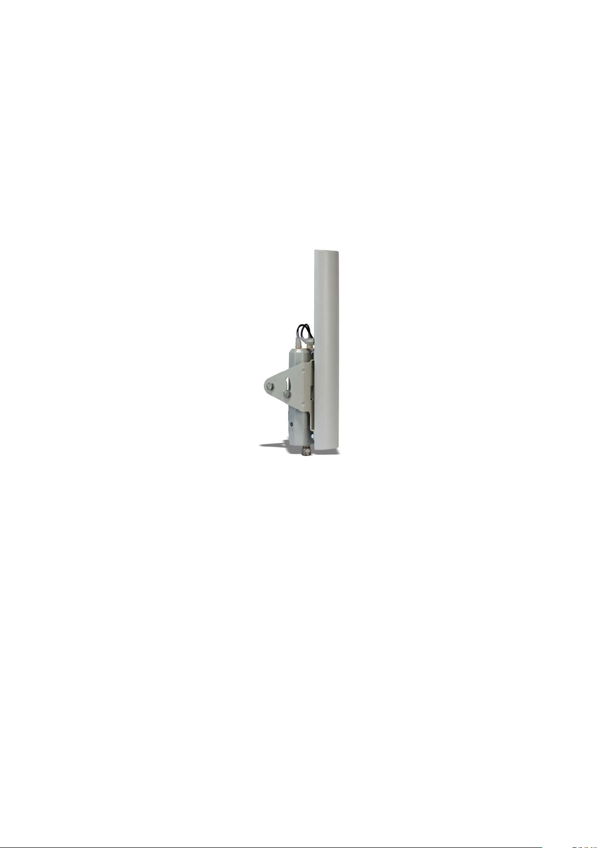
The Fluidmesh 3100 MITO (part number FM3100M-HW, for simplicity re-
ferred to as FM3100) is designed for
The hardware is multi-band sector antenna which can be mounted and
oriented using the supplied pole-mounting adapter as depicted in Fig.
3.5 and Fig. 3.6.
wireless
operations.
Figure 3.5: Fluidmesh 3100 enclosure.
The FM3100 can operate both as a point-to-point wireless bridge or as
a single radio mesh unit. The former operating mode is described in Sec-
tion 4.1 whereas the latter is discussed in Section 4.2.
12
Page 15
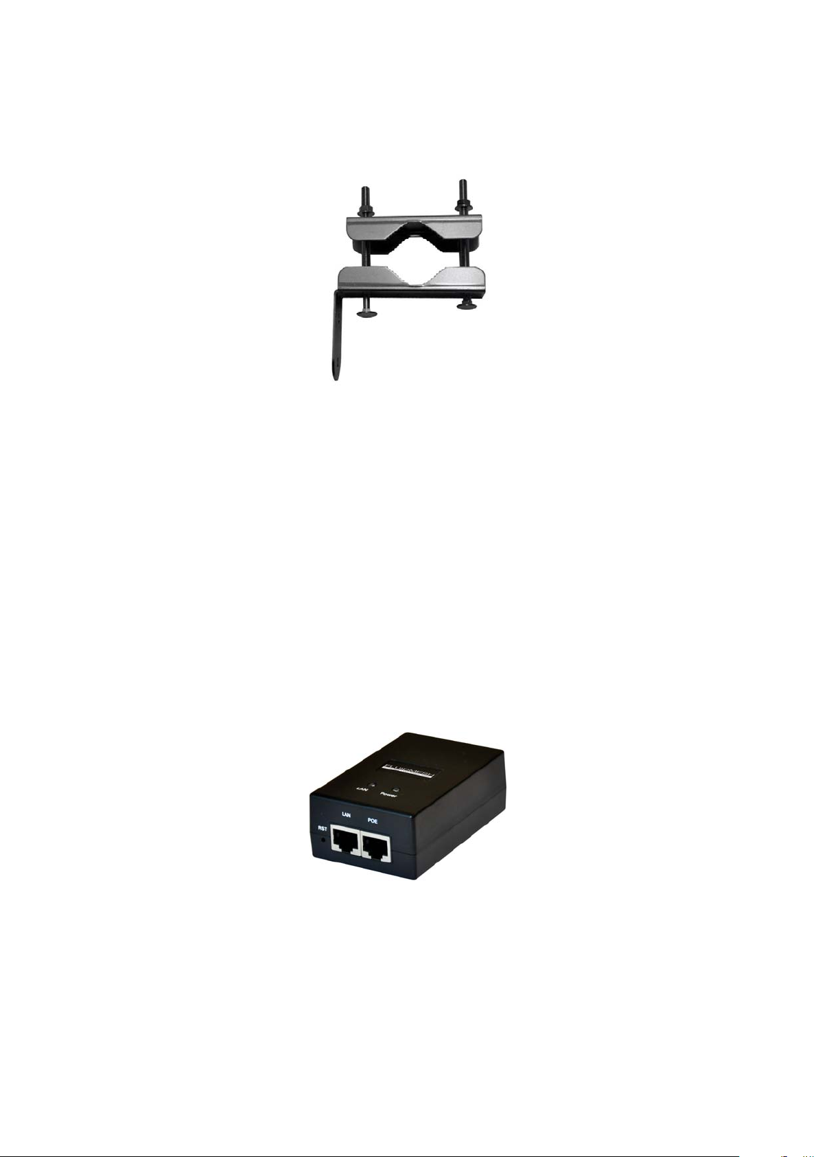
Figure 3.6: Fluidmesh 3100 pole mounting adapter.
3.2.1 Proper Installation Procedures
The FM3100 comes with a pole-mounting adapter, shown in Fig. 3.6, that
allows the installer to change the alignment of the antenna along both the
vertical and the horizontal axis.
3.2.2 Powering on an FM3100
The unit can be powered only with the Power-over-Ethernet injector pro-
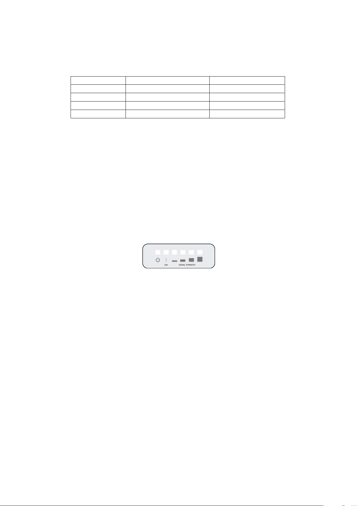
vided with the FM3100 (Fig. 3.7). The PoE injector does not comply with
the 802.3af standard and therefore it cannot be substituted with a different
injector.
Figure 3.7: Fluidmesh 3100 Power-over-Ethernet injector.
The PoE injector must be powered 100-240V 50-60Hz AC using the AC
adapter included.
13
Page 16
LED # (Color) Boot Status Link Quality
1 (Red) Booting core system poor/link absent
2 (Orange) Booting wireless system fair
3 (Green) Booting routing engine good
4 (Green) Booting unit configuration very good
Table 3.3: FM3100 Boot/Link Status LEDs Color Scheme
3.2.3 Status and Link LEDs
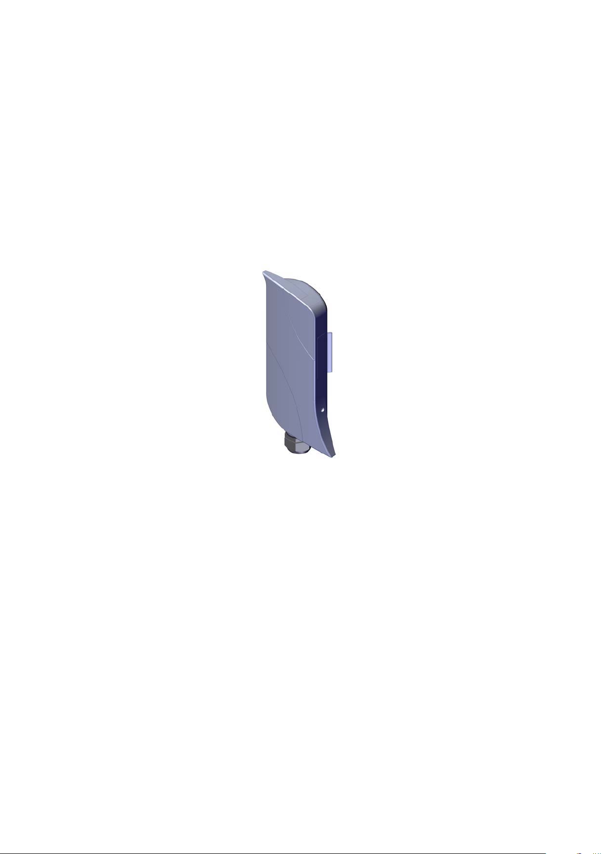
A panel on the back of the FM3100, shown in Fig. 3.8, provides six (6) LEDs
which can be used to check the unit and the link quality status. From the
left-hand side, the first 2 green LEDs indicate the unit power, the Ethernet
port activity, respectively. The remaining 4 colored LEDs indicate the level
of the link signal and can be used for antenna alignment purposes. During
the unit boot-up process, the LEDs indicate the boot status and can be used
for problem detection. Specifically, the 4 colored LEDs light up in sequence
from the leftmost one (red) to rightmost one (bright green). If the LEDs
lighting up sequence does not complete, then an error has been detected
during the booting process. Please refer to Table 3.3 for details.
Figure 3.8: From left to right status LEDs, link/boot LEDs.
3.2.4 Factory Default Hardware Reset
The FM3100 can be reset to factory default using the proper RESET button
present on the PoE injector provided with the unit as shown in Fig. 3.7.
To reset the FM3100 to factory default settings, power up the unit and wait
approximately 40 seconds for the unit to boot up. Once the unit is up and
running, press the reset button for 5 seconds. The FM3100 will restore
the factory default settings and automatically reboot. The LEDs will blink
when the unit receives the reset to factory default signal. After the reset,
the default IP address of 192.168.0.10/255.255.255.0 is restored and the
administrator password is set to admin.
The RESET button can also be used to reboot the unit when pressed for 1
second.
14
Page 17

3.2.5 Integrated Panel Antenna
The FM3100 has an integrated 93 degrees sector antenna that can oper-
ate at 4.9-6.0 GHz. A separate or external antenna cannot be installed or
mounted. The gain of the antenna is 15 dBi at 4.9-6.0 GHz. The specifica-
tions of the integrated panel antenna are reported Table 3.4.
Gain at 4.9-6.0 GHz 15 dBi
Frequency Range 4940-6075 MHz
Polarization Dual Linear
3 dB Beam Angle @ 5470 MHz 93 degrees
Front to Back Ratio 22 dB
Table 3.4: Antenna Specifications
15
Page 18
3.3 Fluidmesh 1200 VOLO
The Fluidmesh 1200 VOLO(part number FM1200V-HW, for simplicity referred to as FM1200) is designed for wireless operations.
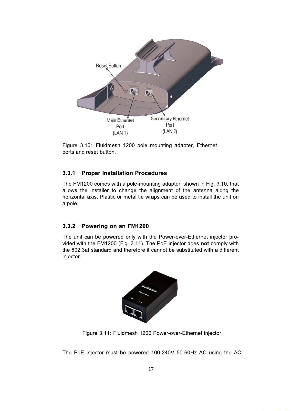
The hardware is multi-band sector antenna which can be mounted and
oriented using the suppliedpole-mounting adapter asdepicted in Fig.
3.9and Fig. 3.10.
Figure 3.9: Fluidmesh 1200 enclosure.
The FM1200 can operate both as a point-to-point wireless bridge or as a
single radio mesh unit. The former operating mode is described in Sec-tion
4.1 whereasthe latter isdiscussed in Section4.2.
16
Page 19
Page 20
LED # (Color) Boot Status Link Quality
1 (Red) Booting core system poor/link absent
2 (Orange) Booting wireless system fair
3 (Green) Booting routing engine good
4 (Green) Booting unit conguration very good
Table 3.5: FM1200 Boot/Link Status LEDs Color Scheme
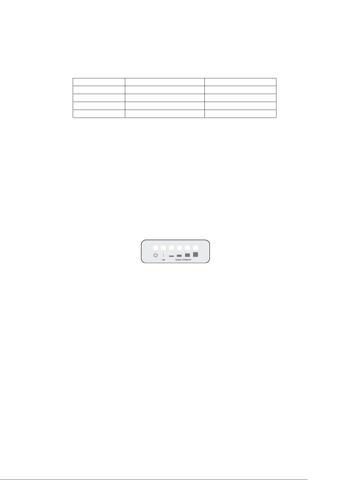
3.3.3 Status and Link LEDs
A panel on the side of the FM1200, shown in Fig. 3.12, provides six (6)
LEDs which can be used to check the unit and the link quality status. From
the buttom up, the first 2 green LEDs indicate the unit power, the Ethernet
port activity, respectively. The remaining 4 colored LEDs indicate the level
of the link signal and can be used for antenna alignment purposes. During
the unit boot-up process, the LEDs indicate the boot status and can be
used for problem detection. Specifically, the 4 colored LEDs light up in
sequence from the leftmost one (red) to rightmost one (bright green). If the
LEDs lighting up sequence does not complete, then an error has been
detected during the booting process. Please refer to Table 3.5 for details.
Figure 3.12: From buttom up status LEDs, link/boot LEDs.
3.3.4 Factory Default Hardware Reset
The FM1200 can be reset to factory default using the proper RESET
button present on the PoE injector provided with the unit as shown in Fig.
3.11. To reset the FM1200 to factory default settings, power up the unit
and wait approximately 40 seconds for the unit to boot up. Once the
unit is up and running, press the reset button for 5 seconds. The
FM1200 will restore the factory default settings and automatically
reboot. The LEDs will blink when the unit receives the reset to factory
default signal. After the reset, the default IP address of
192.168.0.10/255.255.255.0 is restored and the administrator password
is set to admin.
The RESET button can also be used to reboot the unit when pressed for
1 second.
18
Page 21
3.3.5 Integrated Panel Antenna
The FM1200 has an integrated 93 degrees sector antenna that can operate at 4.9-6.0 GHz. A separate or external antenna cannot be installed or
mounted. The gain of the antenna is 15 dBi at 4.9-6.0 GHz. The specifications of the integrated panel antenna are reported Table 3.4.
Gain at 4.9-6.0 GHz 15 dBi
Frequency Range 4940-6075 MHz
Polarization Dual Linear
3 dB Beam Angle@5470 MHz 93 degrees
Front to Back Ratio 22 dB
Table 3.6: Antenna Specifications
19
Page 22

4 Fluidmesh Architecture
Overview
The FM1100, FM1200 and the FM3100 series can be used to create any
kind ofnetwork architecture such as point-to-point links andmesh networks.
More-over, thanks to the innovative FluidMAX™ patent pending
technology, point-to-multipoint links can be created. This also gives to the
user the ability to create mixed networks architectures leading to higher
performance and flexibility in the deployment. In the following section
we describe how to build point-to-point, point-to-
mesh networks with the Fluidmesh products.
4.1 Point-to-Point Wireless Bridge
A wireless bridge enables two local networks (i.e., network segments) to
communicate with each other . The wireless bridge
multipoint, and
20
Page 23

is defined as “transparent” because its activity is transparent to the network
hosts. In other words, the wireless bridge forwards packets from one net-
work segment to the other according to a “forwarding table” which is built
by learning the network topology from the analysis of the incoming traffic.
In this configuration, no explicitinteraction between the wireless bridge and
the network hosts takes place. The two network segments, connected to
both sides of the wireless bridge, will share the same IP addressing class.
Thus, each network host must use a unique IP address, i.e., itis not allowed
to have two devices sharing the same IP address.
4.2 Mesh Network Architecture
This section describes the Fluidmesh mesh networking architecture and the
basic functionalities of the FM1100/
clarity, we will refer to a generic FM unit whenever the discussion applies to
the FM1100,
Fluidmesh Networks develops wireless networking solutions based on the
innovative meshnetworking architecture whichpresents unmatched advan-
tages in terms of reliability and flexibility compared to any traditional wire-
less solution. Using Fluidmesh technology for your network allows you to
take advantage of this powerful architecture. An example of wireless mesh
network is shown in Fig. 4.3. In a wireless mesh network, every FM unit
transmits the data
and also acts as an “intelligent router” able to forward packets coming from
other FM units through the optimal path.
FM1200 and the FM3100series.
packets coming from the devices directly attached to it
FM1200/FM3100 series. For the sake of
21
Page 24

In a redundant and reliable mesh network, every stream of data packets
has multiple available paths to reach the base station, and the network
forwards the packets through the optimal path at any point in time. The
absence of any single point of failure increases its reliability compared to
any other transmission technology, either wireless or wired.
4.3 Point-to-Multipoint Architecture: FluidMAX™
Developing FluidMAX1, Fluidmesh embraced the Point-to-Multipoint archi-
tecture improving its features and capabilities to meet the needs of
system integrators in the security and industrial automation indus-try.
The FluidMAX technology is based on a centralized Medium Access
Control (MAC) protocol and allows Fluidmesh customers to create point-to-
multipoint networks using the FM units.
With the FluidMAX technology, an FM unit can thus be used at the center
of the star topology in a point-to-multipoint fashion using sector antennas
or antenna splitters with multiple directional antennas. The unit operating
at the center of the star topology plays the role of Master and is in charge
of coordinating communications to an
as Slaves. As a result, the hidden and exposed terminal problems are
eliminated by the centralized FluidMAX MAC protocol which supports up
1
Patent pending.
d from the other units which thus act
22
Page 25

to 100 Mb/s maximum throughput.2By reducing the number of slaves, the
supported rate per slave can be increased provided that the sum of the
throughput requirements of the slaves is lower than or equal to 100 Mb/s.
FluidMAX is fully automatic and integrated within the mesh architecture. By
continuously monitoring the network topology, FM units are able to auto-
matically select whether to operate the FluidMAX MAC protocol or remain
in the initial mesh operating mode. Consequently, no additional configura-
tion is needed to enable the FluidMAX features because the communica-
tion protocol is automatically chosen by the FluidMAX protocol based on
the detected network topology.
2
We assume the default channel width of 40 MHz.
23
Page 26
5 Fluidmesh Network
Addressing
5.1 Bridge IP Addressing
The FM unit can be operated in bridge mode to create a single point-
to-point connection between two network segments as described in Sec-
tion 4.1.
Each FM unit is provided with a default IP address for its wired Ethernet
port(s), which is:
192.168.0.10
No IP address is associated to the wireless interface.
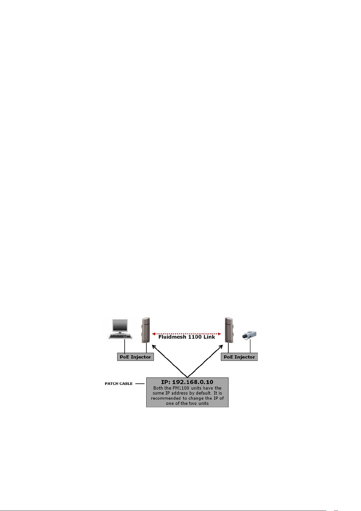
When you set up a wireless bridge using two FM units for the first time,
both units will have the same default IP address equal to 192.168.0.10. It is
recommended to change the IP address of one of the two units in order to
unambiguously address and configure the system with no confusion (see
Fig. 5.1).
Figure 5.1: Wireless network architecture and initial bridge configuration.
24
Page 27

5.1.1 Connecting and Configuring IP Devices and Cameras
The FM3100 mounts one Ethernet port and the FM1100 andFM1200 is
equipped with 2 Ethernet ports that can be used to connect a camera or
other Ethernet-compatible device. You should directly connect any
device using an Ethernet cable to the PoE injector. Use a patch
Ethernet cable to connectthe PoE injector to the FM unit.
FM1100 the second Ethernet port can be used to power any 12-18V
passive PoE device.Therefore, multiple FM unit can be connected
together in a daisy chain fashion if
The camera or the device attached to the FM unit should use an IP address
belonging to the same class of the devices on the other network segment
of the wireless bridge.
The default IP address class is 192.168.0.0/255.255.255.0.
required.
5.2 Mesh Addressing
The FMunits havetwo modes of operation which are usedto developmesh
network architectures:
• Mesh Point Mode
• Mesh End Mode
Mesh Point Mode: it is the default mode for the FM unit. Each unit in the
field that is not connected to the wired LAN backbone must be set in Mesh
Point Mode.
Mesh End Mode: in the Fluidmesh network, an FM unit that is connected
to the main wired LAN must be set in Mesh End Mode. The Mesh End unit
is the junction point between the wireless network and any IP-based wired
network.
Regardless of its configuration, any FM unit comes from the factory with a
unique unit ID with the following format:
5.a.b.c
where the triplet (a,b,c) unambiguously identifies the unit and cannot be
changed. The unit ID is used to identify the units throughout the Web-
based Graphical User Interface (GUI).
25
Page 28
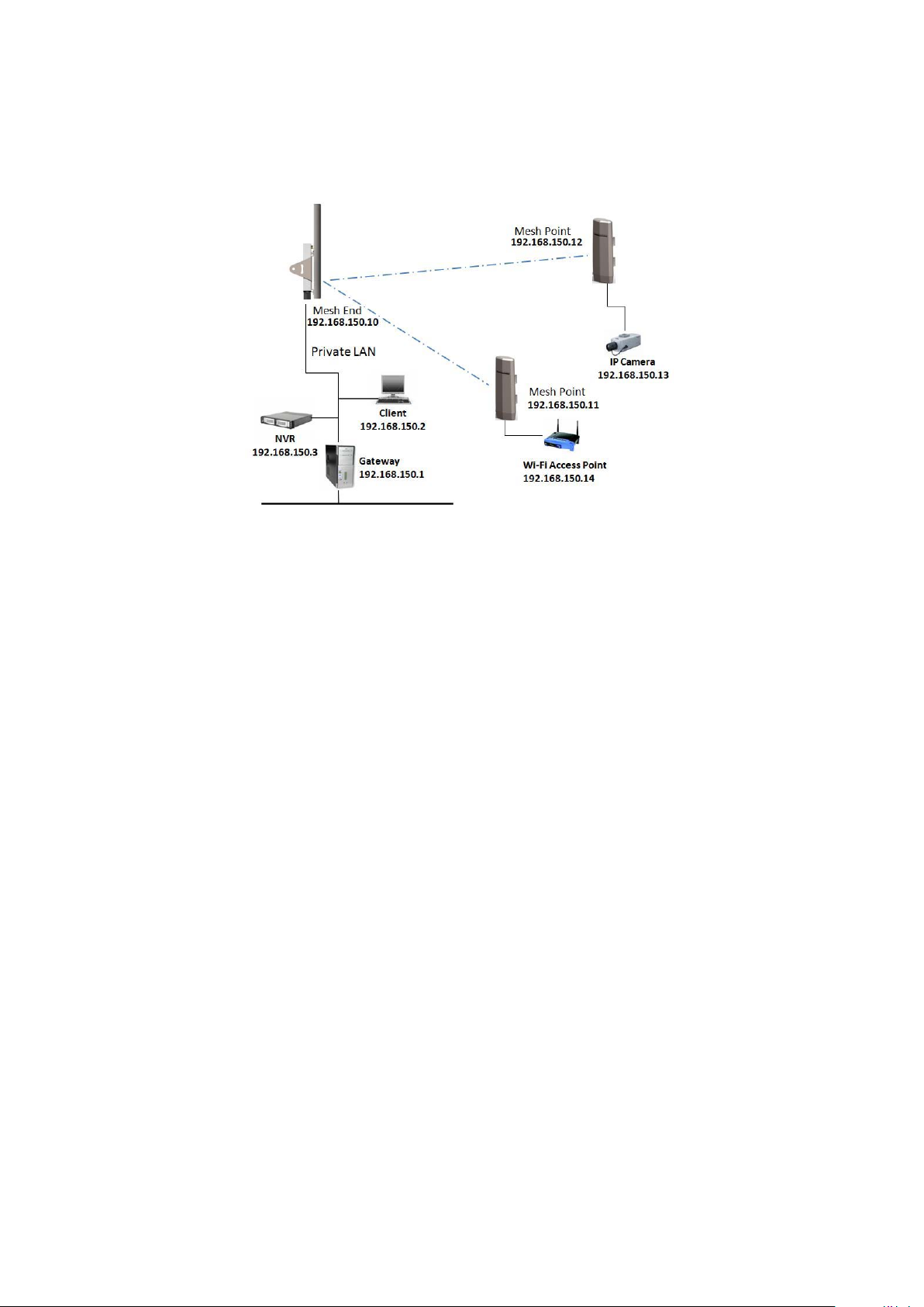
Figure 5.2: Fluidmesh network addressing.
5.2.1 Network Addressing
The Fluidmesh layer 2 addressing allows configuring each FM unit and
each device connected to the FM units according to the IP address class
used within the private LAN to which the Mesh End unit is connected. A
sample network configuration is shown in Fig. 5.2.
The Fluidmesh network logically becomes part of the private LAN where
(usually) the control room resides. Therefore, both the FM units and any
other edge device should be provided with a private LAN IP address and
will be accessed through that specified IP address.
Consider the example depicted in Fig. 5.2 where the private LAN IP ad-
dress class is 192.168.150.0 with netmask 255.255.255.0. Each device is
configured with an IP address belonging to this class. Please note that
each IP address must be univocal within the entire network to avoid ad-
dress conflicts. The default IP address of each FM unit is 192.168.0.10
with netmask 255.255.255.0. Finally, please note that the default factory-
set 5.a.b.c unit IDs are still valid and used to unambiguously identify each
FM unit.
Multiple FM units can be connected together through a network switch to
form clusters of radios if needed. The Fluidmesh
col will be run automatically on the cabled segment of the network. Please
note that the units must be operated in Mesh Point mode only to activate
the cluster feature.
26
proprietary routing proto-
Page 29
Connecting and Configuring an Ethernet Edge-device
The FM unit Ethernet ports can be used to connect all kinds of Ethernet
edge devices (e.g. IP Cameras, Video-Servers, Wi-Fi Access Points, etc.).
Any Ethernet device can be configured either manually or automatically
through a DHCP server.
A manual IP setting is recommended in any video-surveillance system where
the cameras need to have a fixed custom IP address to be accessed by the
video-recording software.
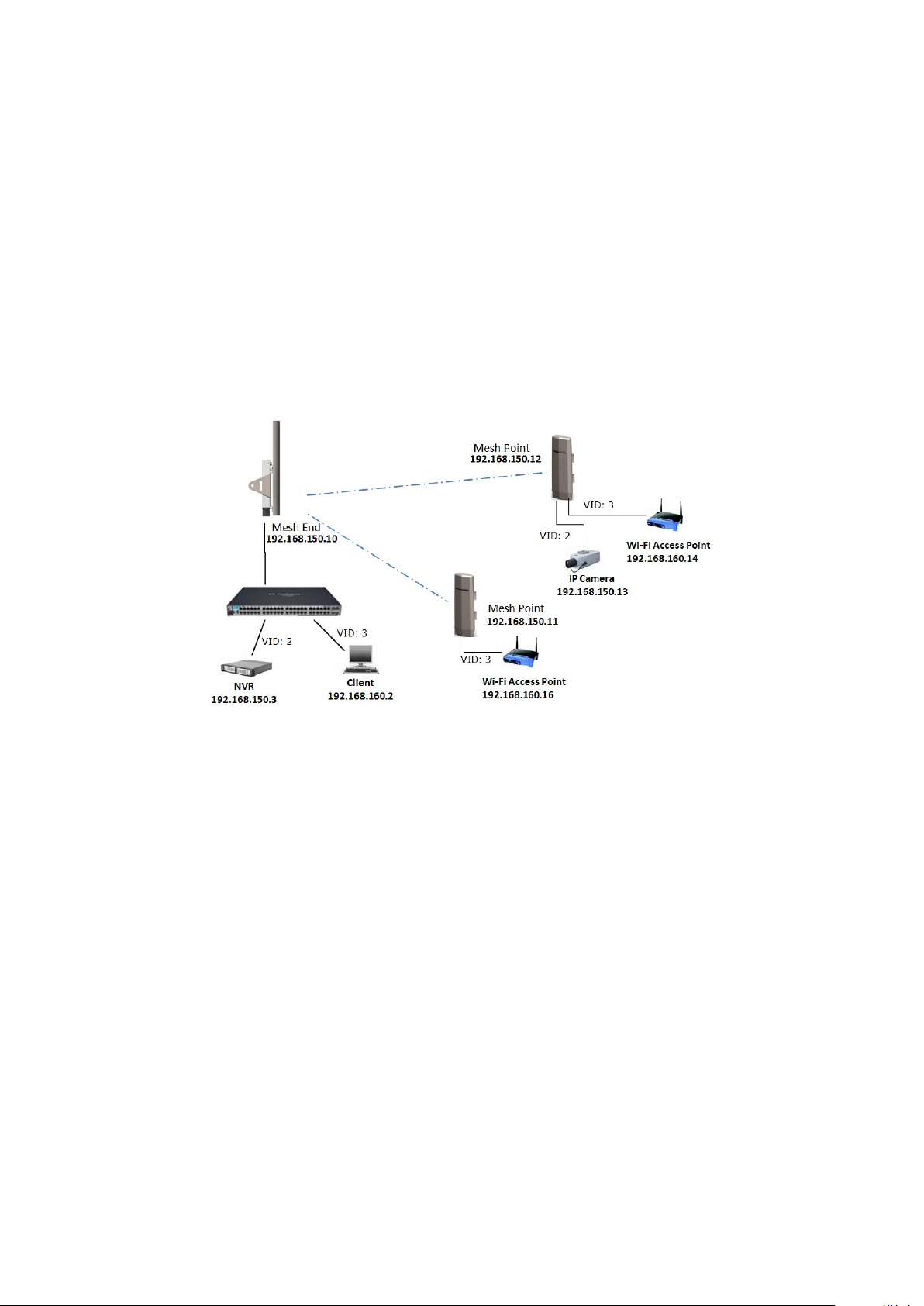
Figure 5.3: Network configuration with two port-based VLANs.
VLAN Tagging (Software Plug-in Required)
Virtual LAN (VLAN) tagging (or IEEE 802.1q) is a networking standard al-
lowing multiple switched networks to transparently share the same physical
hardware without the leakage of information between networks. For exam-
ple, consider a company with several departments. With VLAN tagging,
a separate private logical network is made available for each department
while using only one physical corporate network. Each VLAN is identified
by a specific number called VLAN ID (VID) which is also used for tagging
packets belonging to the same VLAN. Because VLANs are based on logi-
cal instead of physical connections, several types of VLANs exist based on
the criteria adopted to logically separate networks. The traditional VLAN
scheme is port-based where each physical Ethernet port is configured
specifying membership in a VLAN. However, if there are requirements that
27
Page 30

individuals or devices must be segregated regardless of their physical lo-
cation, the MAC-based VLANs can be used. In this case, the network is
configured with an access list mapping individual MAC addresses to VLAN
membership. Other, less common, types of VLANs exist like the protocol-
based VLANs, where the protocol type is used to separate networks.
VLAN tagging is usually supported by network switches with advanced
capabilities. The wireless networks can be viewed as a large distributed
switch with VLAN support. Two different types of VLAN tagging mecha-
nisms are supported: port-based and mac-based VLANs. Fig 5.3 reports
a network configuration example where two VLANs are set up, i.e. using
VID #2 and VID #3. Each VLAN uses a separate IP address class and the
devices belonging to the VLANs must be configured accordingly.
The Fluidmesh VLAN implementation is compatible with the specification
of the IEEE 802.1q standard and, thus, the Fluidmesh network can interop-
erate with other VLAN-aware network devices. VLAN trunking between the
Fluidmesh network and the Ethernet switches is also supported to enable
carrying VLAN membership information throughout the wireless and wired
network segments.
The VLAN tagging can be enabled and configured through the Web inter-
face as described in Section 7.11.1.
Multicast Streaming
To enable multicast video-streams from IP cameras or video-encoders, no
multicast group setting is required. Every multicast packet will be forwarded
by the Mesh Point unit towards the closest Mesh End unit. Please refer to
Section 7.15 for additional details.
28
Page 31
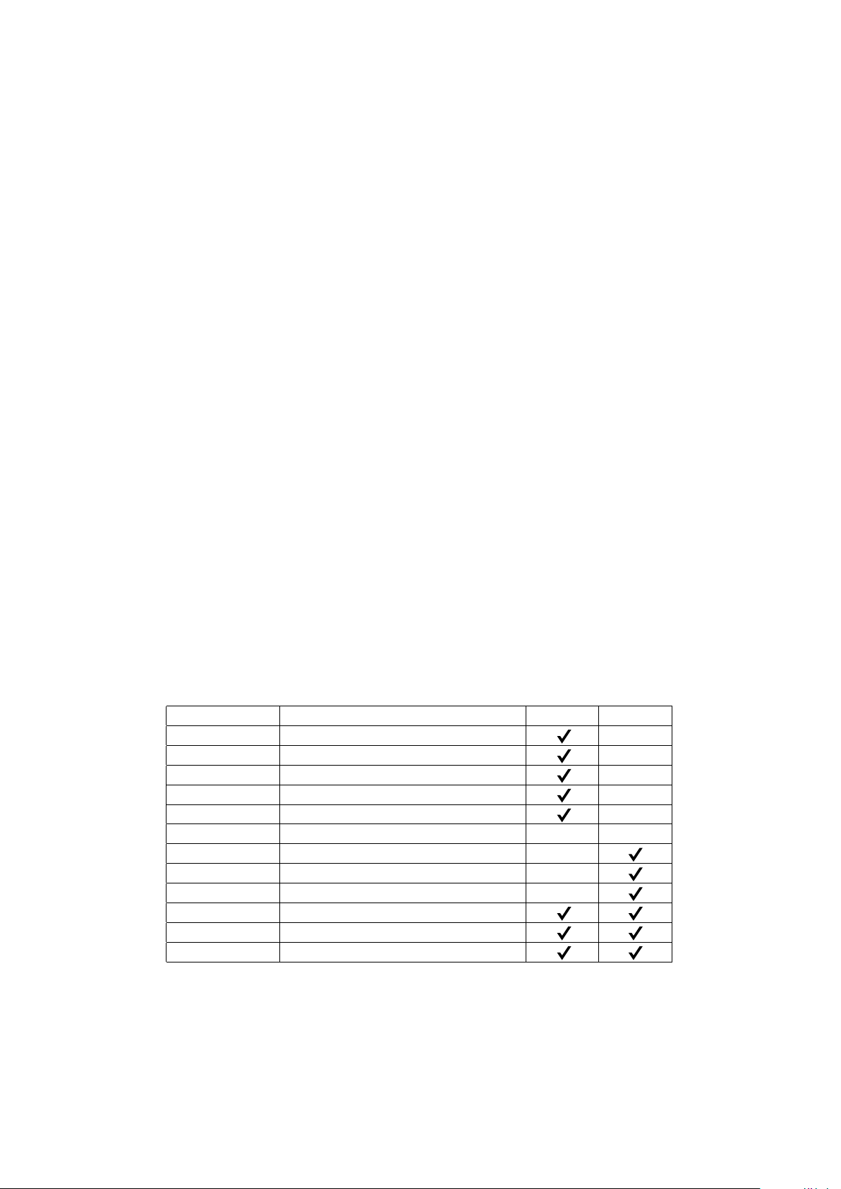
6 Software Plug-ins
The Fluidmesh 1100 MITO (part number FM1100M-HW), Fluidmesh
1200VOLO (part number FM1200V-HW)
number FM3100M-HW) feature the innovative FluidThrot-tle™ technology
which provides a variable software-upgradable capacity of the Ethernet
port based on the user’s needs. On the Fluidmesh 1100 and
Fluidemsh1200, the user can purchase software-based Plug-ins to
increase the maximum capacity of the Ethernet port from 1 Mb/s to 100
Mb/s depending on the system’s bandwidth requirements. On the
Fluidmesh 3100, the user can purchase software-based Plug-ins to
increase the maximum capacity of the Ethernet port from 10 Mb/s to 100
Mb/s depending on the system’s band-width requirements. The
FluidThrottle technology follows the cost-effective “What You Need Is
What You Get” philosophy which provides the user with maximum flexibility
in choosing (and paying for) what he/she exactly needs.
FM1200V-HW
Port Capacity of 1 Mb/s. FM3100M-HW part number includes the hardware
and the default Ethernet Port Capacity of 10 Mb/s.
part numbers include the hardware and the default Ethernet
and the Fluidmesh 3100 MITO (part
FM1100M-HW and
Part Number Description
FM1100M-02
FM1100M-05
FM1100M-10
FM1100M-30
FM1100M-60
FM1100M-UN
FM3100M-30
FM3100M-60
FM3100M-UN
FM-AES
FM-49
FM-LF
Ethernet Capacity up to 2.5 Mb/s
Ethernet Capacity up to 5 Mb/s
Ethernet Capacity up to 10 Mb/s
Ethernet Capacity up to 30 Mb/s
Ethernet Capacity up to 60 Mb/s
Ethernet Capacity up to 100 Mb/s
Ethernet Capacity up to 30 Mb/s
Ethernet Capacity up to 60 Mb/s
Ethernet Capacity up to 100 Mb/s
128-bit AES Encryption
4.9 GHz Band
Licensed Frequencies
Table 6.1: Software Plug-in upgrades.
FM1100 FM3100
29
Page 32
Page 33

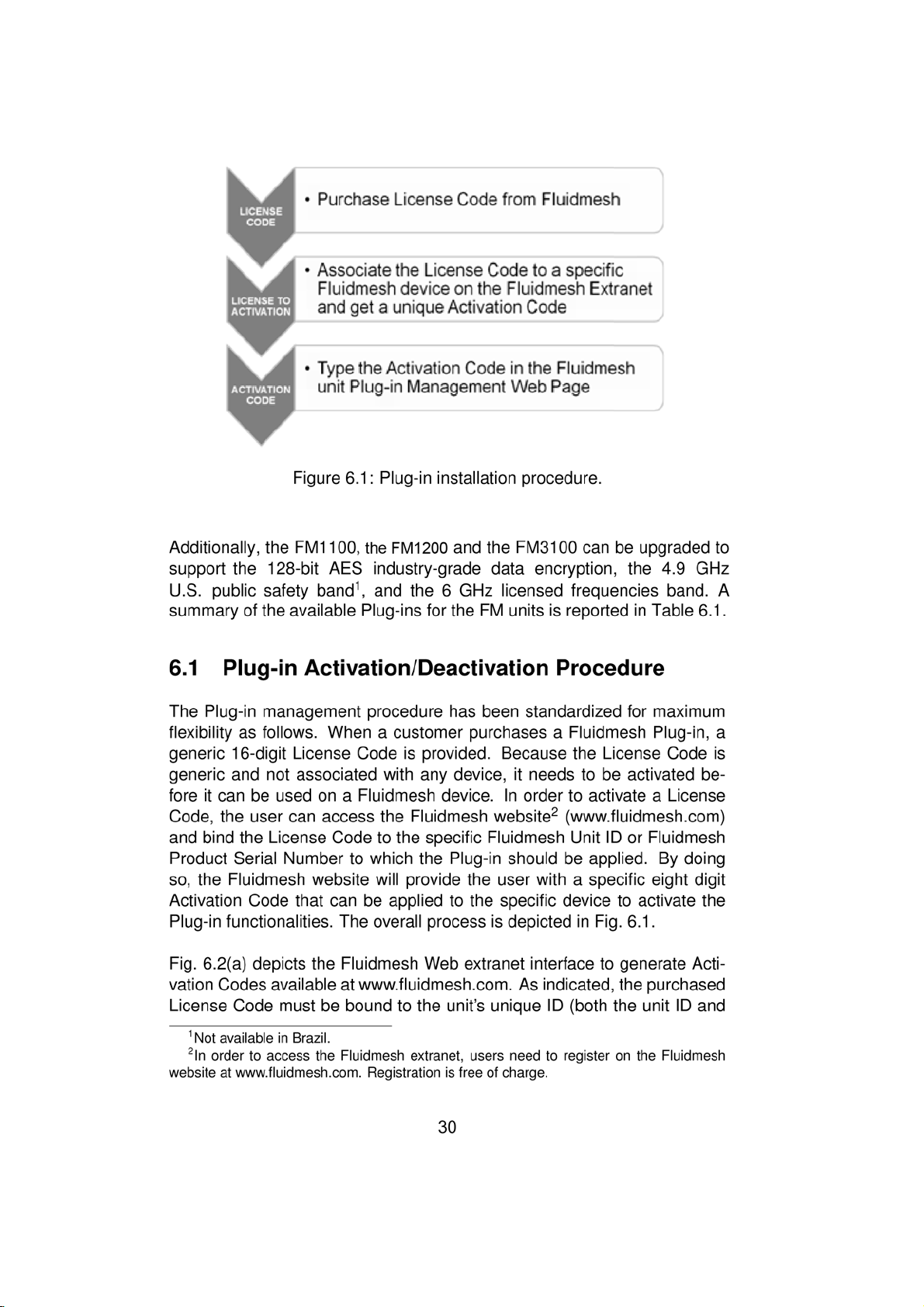
the Serial Number are accepted) in order to get the Activation Code. Please
refer to Section 7.13 to input the Activation Code into the unit Web interface.
To provide the maximum flexibility in the Plug-in management, Fluidmesh
allows the deactivation of any installed Plug-in in order to transfer it to an-
other Fluidmesh unit. Specifically, each Plug-in can be deactivated via the
Web interface of the unit according to the procedure described in Sec-
tion 7.13. A Deactivation Code is provided by the unit which can be input
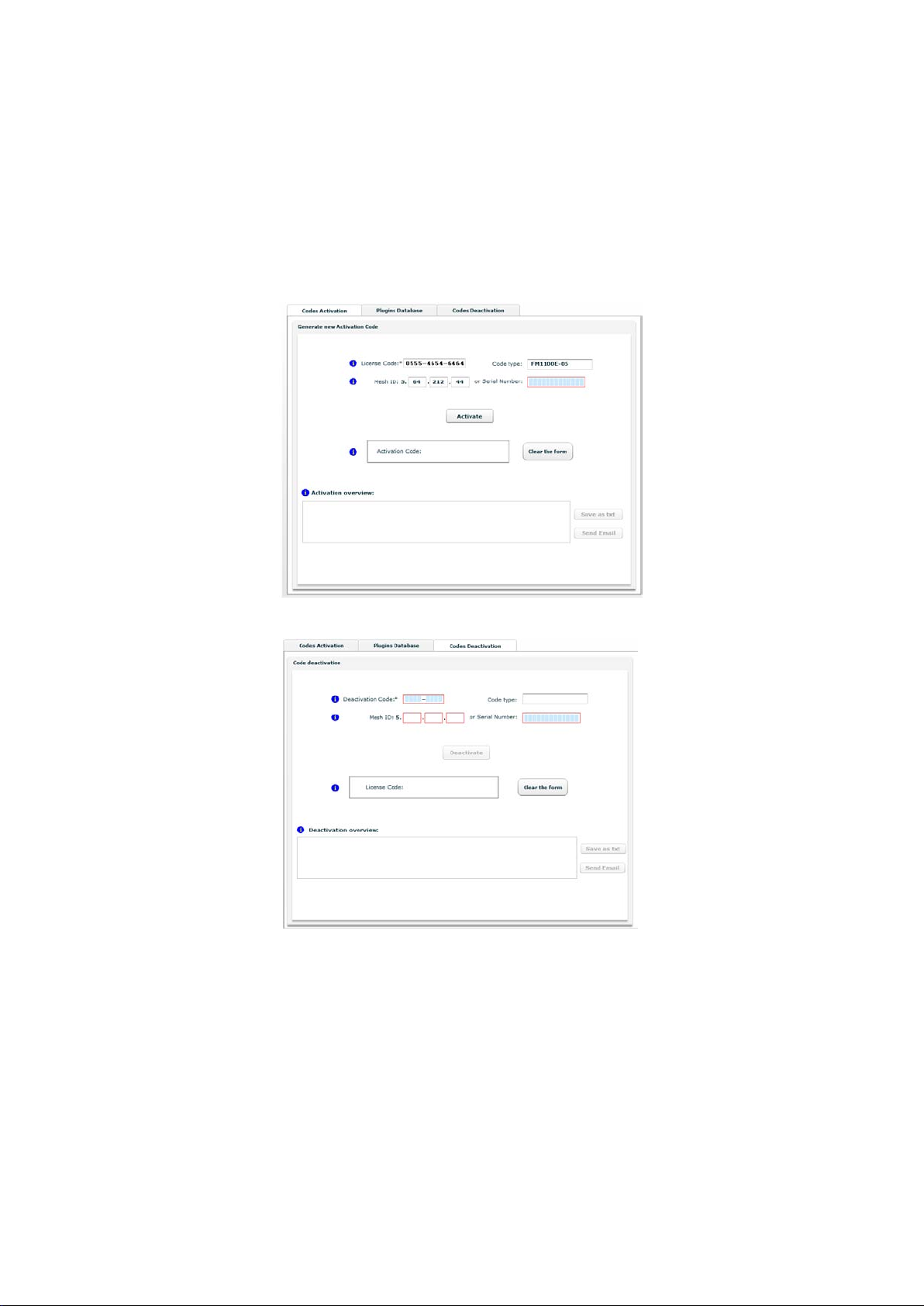
in the Fluidmesh Plug-in Management Web Page on Fluidmesh Extranet to
generate a fresh License Code as depicted in Fig. 6.2(b). The latter can
then be used to generate a new Activation Code to activate the Plug-in for
a different unit.
31
Page 34
(a) Plug-in Activation
(b) Plug-in Deactivation
Figure 6.2: Activation/Deactivation Code Generation Web interface avail-
able at www.fluidmesh.com.
32
Page 35

7 Web-based Interface and
Configuration
Every FM unit can be configured and managed using a Web-based Graph-
ical User Interface (GUI). By default, each FM unit is configured in Bridge
Mode with the Bridge IP address 192.168.0.10 and netmask 255.255.255.0.
To change the settings on the units, you need to log-in to the Web-based
interface.
7.1 Software and Hardware Requirements
To log-in to the Web GUI, you need a PC with a Web-browser, an Ethernet
port, and an Ethernet cable.
Requirements List:
• Cat5 Crossover Ethernet cable with RJ45 connectors.
• PC with the following characteristics:
– Windows XP or Windows 2000. In this manual, we assume use
of Windows XP and every instruction or screenshot is based on
this assumption. The device can also be configured using other
operating systems, such as Linux, MAC OS, or older versions of
Windows.
– Microsoft Internet Explorer 6. In this manual, we assume use
of Microsoft Internet Explorer 6 or newer. A Fluidmesh device
can also be configured using other browsers such as older versions of Internet Explorer, Firefox or Safari but the configuration
using these browsers has not been thoroughly tested.
– Wired Ethernet Network Card.
– Hardware Requirements. Typical PC hardware allowing for
proper operations of Windows XP and Microsoft Internet Explorer 6.
33
Page 36
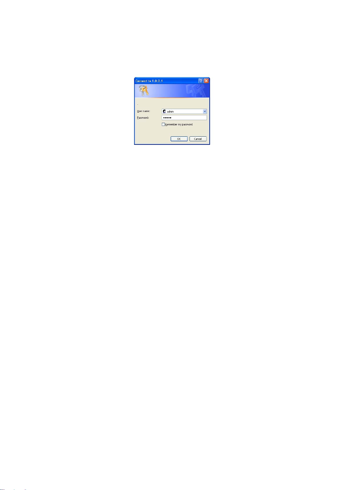
Figure 7.1: Log-in window.
7.2 Logging-in to the Web-based Interface
Power up the device after making sure the antennas are properly con-
nected. Wait for about one minute for the initialization to be completed.
Connect an Ethernet cable with RJ45 connectors between a computer and
the Fluidmesh device that you want to configure.
Configure the wired Ethernet port of your computer according to the de-
fault class “C” IP address of the device, e.g., IP: 192.168.0.30, Netmask:
255.255.255.0.
If you do not know how to configure your Windows PC, please refer to Sec-
tion 8 where the manual IP configuration process is described. Disable
the Access the Internet using a proxy server function. To disable this
function, go to Control Panel > Internet Options > Connections > LAN
Settings and uncheck the Enable box. Disable the wireless Wi-Fi card of
your PC if present to avoid routing issues between the two network inter-
faces of your computer. Open a Web-browser such as Internet Explorer
and type the following URL:
http://192.168.0.10
Make sure not to omit the initial “http://”. Some browsers might not work
without the “http://” prefix preceding the numeric address. A log-in form
asking for a username and a password should appear as shown in Fig. 7.1.
To preserve the security of your system, make sure you change the default
password once the entire installation is completed. In case the log-in form
does not appear, please refer to Section 8.
34
Page 37
The default username and a password are:
Username: admin
Password: admin
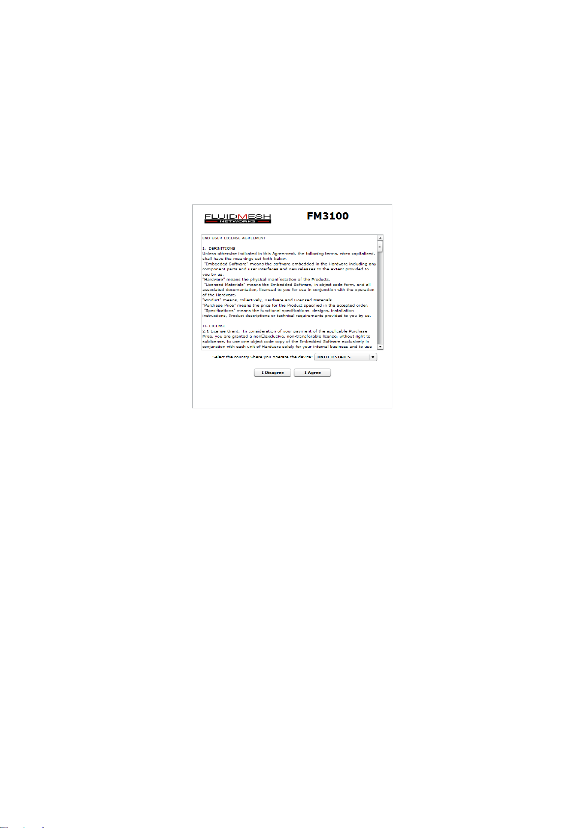
Figure 7.2: End-user license agreement.
7.3 End-user License Agreement and Region of Operation
The first time you log-in, you will be asked to accept the terms of the enduser license agreement and select the country where you will be operating
the unit (Fig. 7.2 is an example for an FM1100 unit). You must accept the
terms of the license agreement in order to activate the device. If you do not
wish to accept the terms of the license agreement, please turn off the unit
and contact Fluidmesh Networks. Choosing a wrong country/regulatory domain setting may lead to an illegal wireless configuration.
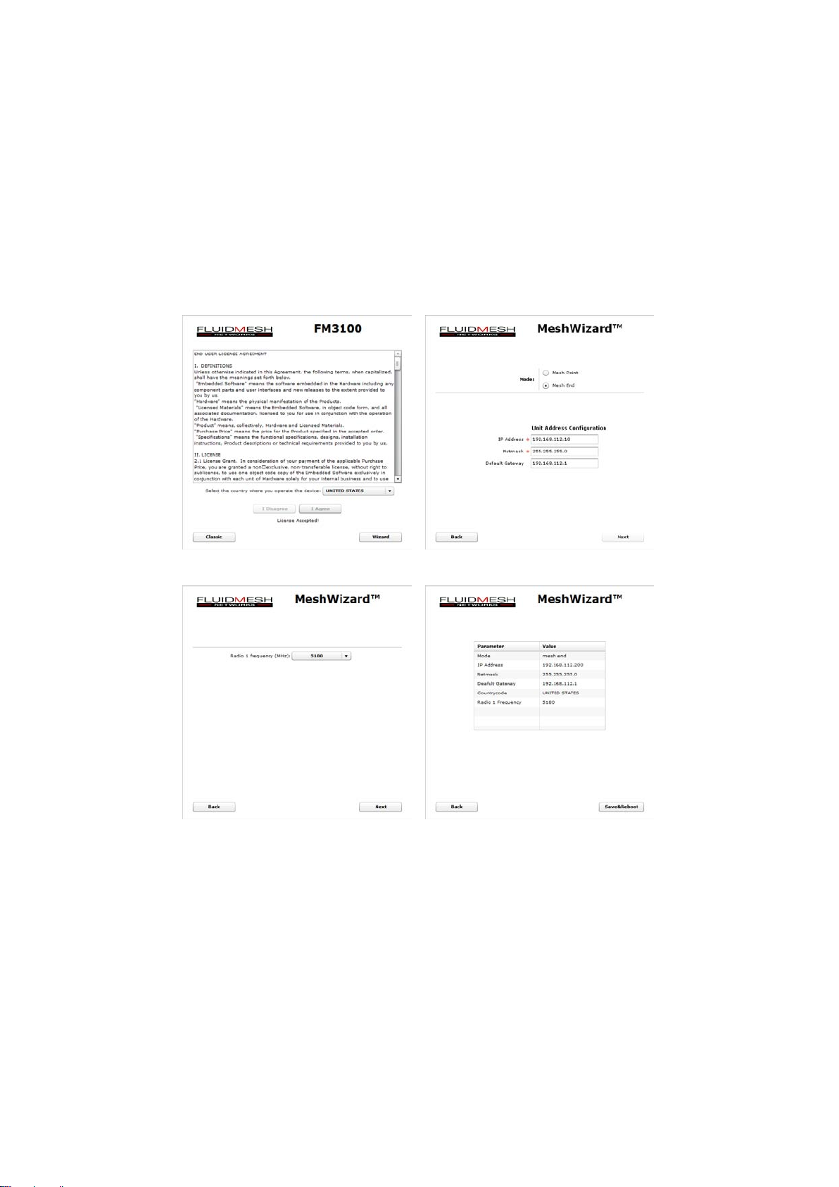
Once the license is accepted, the unit can be configured. Two configuration methods are available as shown in Fig. 7.3(a): MeshWizard™ and
Classic. The former consists of a simple four step wizard to configure the
basic settings of the unit (see Section 7.4), whereas the latter is the classic
Fluidmesh Web-based GUI for advanced configuration (see Section 7.5).
35
Page 38
(a) Step 1 (b) Step 2
(c) Step 3 (d) Step 4
Figure 7.3: MeshWizard™ FM unit configuration steps.
36
Page 39
7.4 MeshWizard™
MeshWizard is a simple yet effective tool to configure the basic settings of
an FM unit based on the following four steps:
1. Step 1, Fig. 7.3(a): click on the “Wizard” button to start configuring
the unit;
2. Step 2, Fig. 7.3(b): unit IP configuration;
3. Step 3, Fig. 7.3(c): wireless radio frequencies configuration;
4. Step 4, Fig. 7.3(d): settings summary and configuration save.
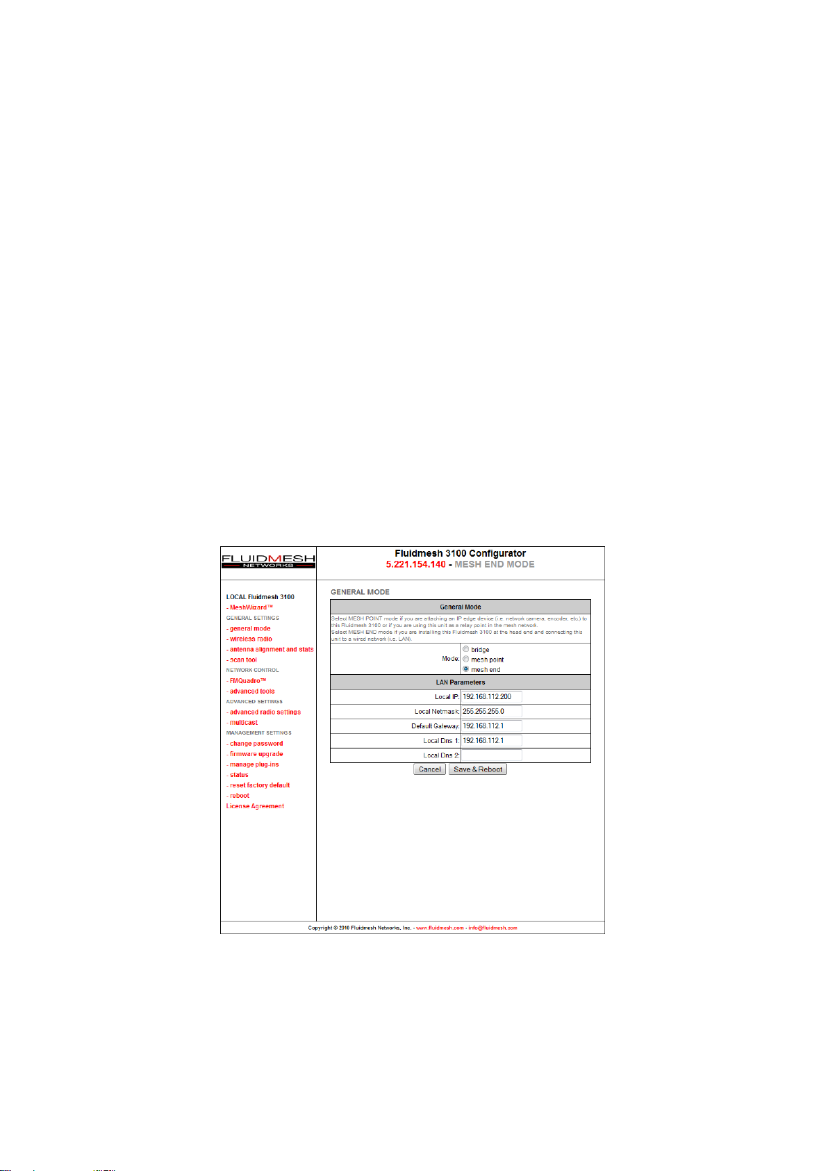
7.5 Web-based Interface Menus
Once logged in successfully, the general mode page will appear as shown
in Fig. 7.4. Through this page you can change the mode of operation of
the FM unit. The item list menu on the left can be used to set/modify the
configuration of the unit.
Figure 7.4: FM unit general configuration window.
37
Page 40

7.6 General Mode
Every FM unit has three possible modes of operations:
• Bridge Mode
• Mesh Point Mode
• Mesh End Mode
The FM unit factory default mode is Bridge. The Mesh Point mode must be
used for any unit deployed in the field. On the other hand, the FM unit must
be set in Mesh End whenever it is connected to the main cabled network
where the control room (usually) resides. You will need to input the settings
of the wired network (LAN) to which the FM unit unit will be connected. The
default IP address of the FM unit is 192.168.0.10 and the default Netmask
is 255.255.255.0. If you do not know the LAN settings, contact the local
network administrator before changing the settings of the gateway.
Please remember that a Mesh End unit is always necessary for the correct
mesh network operations, even for small networks (e.g., 2 FM units).
7.7 Wireless Settings
The wireless settings menu is used to configure the radio present in the
FM unit and can be accessed by clicking on wireless radio. The wireless settings menu is available in either Basic (Fig. 7.5) or Advanced mode
(Fig. 7.6). The former provides the basic radio configuration options whereas
the latter can be enabled by expert users for tuning the radio channel width
or using non-standard carriers. The following wireless parameters are available:
Shared Passphrase. The shared passphrase is a shared secret that must
be set in every FM unit forming a wireless network. Any Fluidmesh device
that does not have the correct passphrase will not be able to be part of the
network. Different passphrases can also be used to create separate Fluidmesh networks in the same area and sharing the same frequencies.
Country. You need to specify the country where you will operate the unit.
Different countries have different telecommunications regulations. Setting
the country properly allows you to operate in compliance with national regulations. The available frequencies and other settings related to the RF operation will vary based on the selected country. Choosing the wrong country/regulatory domain may lead to an illegal operation of the unit. Please
38
Page 41
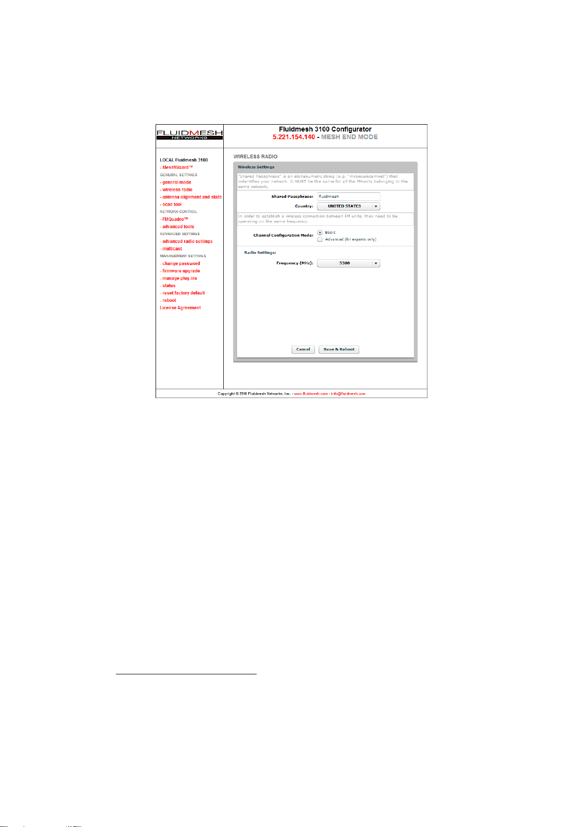
Figure 7.5: Wireless parameters configuration. Basic mode
make sure the country has been properly specified before changing the frequency of the system.
Frequency Selectors. All Fluidmesh units are equipped with multi-band
radios capable of operating on the 4.9-6 GHz bands.1You can change the
frequency of each radio in order to minimize interference with other wireless networks operating in the same area. The frequencies listed on the
Frequency Selector are the carrier frequencies. In Basic mode, each radio operates using fixed channel carriers with 40 MHz channel widths as
specified by the local country regulations. In Advanced mode, the user is
allowed to select any channel carrier in the local country frequency band
with a 5 MHz granularity. The channel width can be set through the specific
selector (see below). Make sure you pick non-overlapping channels if you
need to operate more than one unit in the same area.
In Advanced mode, the following selectors are also available:
1
4.9 GHz and 6 GHz are licensed bands which must be enabled through the proper
software plug-in. Please refer to Section 7.13 for details.
39
Page 42
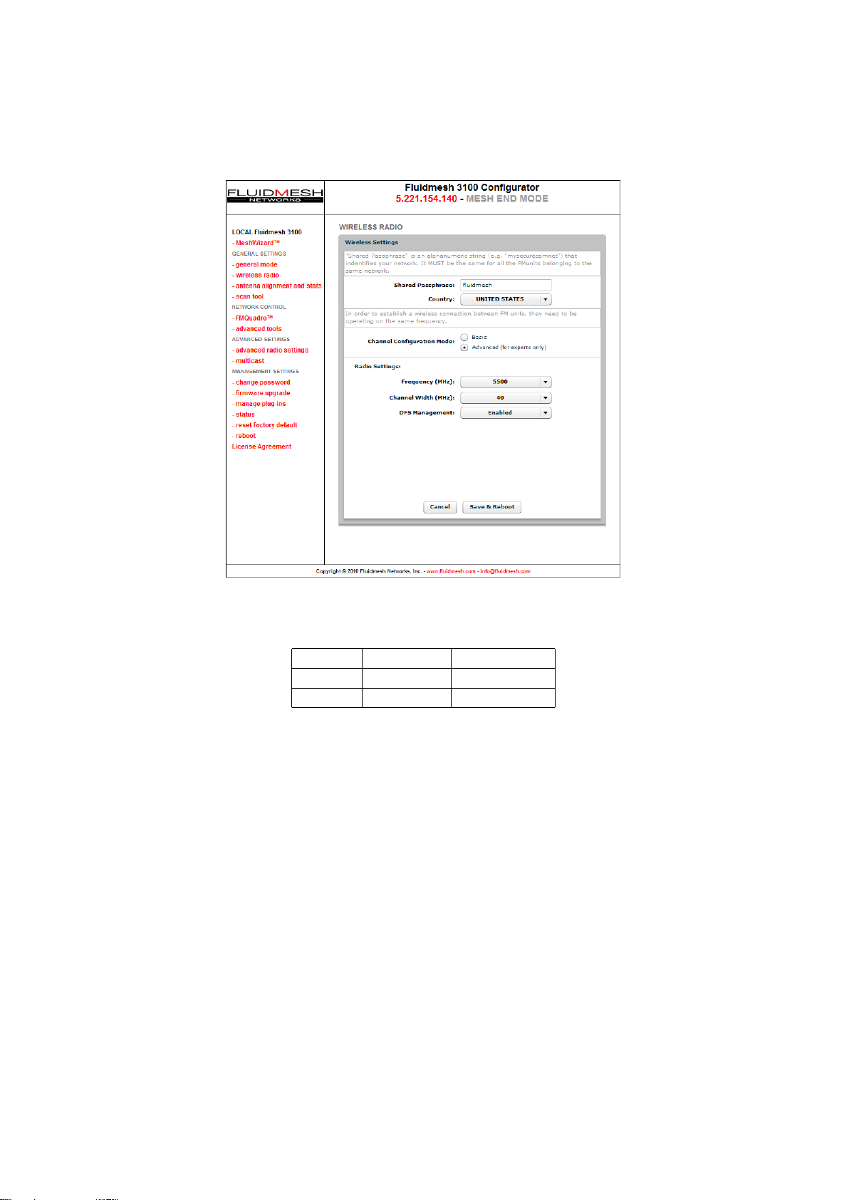
Figure 7.6: Wireless parameters configuration. Advanced mode
Width Data Rate Throughput
20 MHz 150 Mb/s 60 Mb/s
40 MHz 300 Mb/s 100 Mb/s
Table 7.1: Available radio channel widths.
Channel Width. The width of the operating radio channel can be set
through this selector. The available options are described in Table 7.1
where the theoretic data rate and the achievable throughput are also indicated for each channel width.
Whenever possible, setting the radio to operate on a narrower channel can
be useful to reduce the interference in the network and to increase the number of available channels. Please remember to set the same channel width
on both sides of the wireless link. A channel width mismatch will prevent
the FM units from communicating properly. Please note that changing the
channel width may violate the local telecommunication authorities guide-
40
Page 43

lines and lead to illegal wireless operations.
IN NO EVENT SHALL FLUIDMESH NETWORKS, INC. BE LIABLE FOR
ANY INCIDENTAL, CONSEQUENTIAL OR SPECIAL DAMAGES, WHETHER
BASED ON TORT, CONTRACT, OR OTHERWISE, ARISING OUT OF OR
IN CONNECTION WITH IMPROPER USE OR OPERATION OF THE CHANNEL WIDTH FUNCTIONALITIES.
DFS Management. Each device implements a proprietary distributed channel switching algorithm which is used when a radar is detected to comply with the Dynamic Frequency Selection (DFS) international regulations.
Upon radar detection, two communicating Fluidmesh units agree to switch
to the next radar-free channel so that they can continue to communicate on
that channel. The DFS is automatically enabled in the following frequency
ranges: 5.250 GHz – 5.350 GHz and 5.470 GHz – 5.725 GHz. The DFS
management can be manually disabled. The number of detected radars is
reported as well. Outside these mandatory frequency bands, the DFS is
not required and it is disabled by default. Please note the DFS is required
by law in many countries and by disabling it you might incur fines and criminal charges by the local telecommunication authorities.
IN NO EVENT SHALL FLUIDMESH NETWORKS, INC. BE LIABLE FOR
ANY INCIDENTAL, CONSEQUENTIAL OR SPECIAL DAMAGES, WHETHER
BASED ON TORT, CONTRACT, OR OTHERWISE, ARISING OUT OF OR
IN CONNECTION WITH IMPROPER USE OR OPERATION OF THE DFS
FUNCTIONALITIES.
41
Page 44

Option Specification
AUTO The FluidMAX engine is enabled and the unit role is set
automatically.
MASTER The FluidMAX engine is enabled and the unit role is set to
MASTER. This is used to force the FluidMAX role of the
Fluidmesh unit at the center of the star topology to be a
MASTER.
SLAVE The FluidMAX engine is enabled and the unit role is set to
SLAVE. This is used to force the FluidMAX role of the unit
which is NOT the center of the star topology to be a SLAVE.
OFF The FluidMAX engine is disabled.
Table 7.2: FluidMAX Management options.
7.8 Advanced Wireless Settings
The advanced wireless settings menu (Fig. 7.7) can be used to configure
advanced wireless parameters:
FluidMAX Management. Although the FluidMAX engine automatically selects the most appropriate MAC protocol to be used according to the detected network topology, convenient selectors are included in the Web GUI
to force the FluidMAX operations and control the FluidMAX role of the unit.
Please refer to Table 7.2 for the available options and their specification.
Transmission Rate Selection. Each FM unit implements a proprietary
data-rate selection algorithm which is able to adapt to the specific radio
channel conditions. Through this setting, it is possible to force the rate selection algorithm to limit the modulation speed at a specific rate. This option
might be useful with unstable channel conditions.
Maximum TX Power. This setting controls the output power of the radio.
By decreasing the output power of a radio, you can decrease the overall
E.I.R.P. By default, the radio transmission power is controlled automatically
by the innovative Fluidmesh Transmission Power Control (TPC) algorithm.
The Fluidmesh TPC algorithm tries to obtain an optimal link signal strength
(about -55 dBm) on both sides of the link while not exceeding the maximum
TX power which can be set by the user through the selector. Note that the
maximum transmission power may vary depending on the operating frequency channel of the radio.
42
Page 45
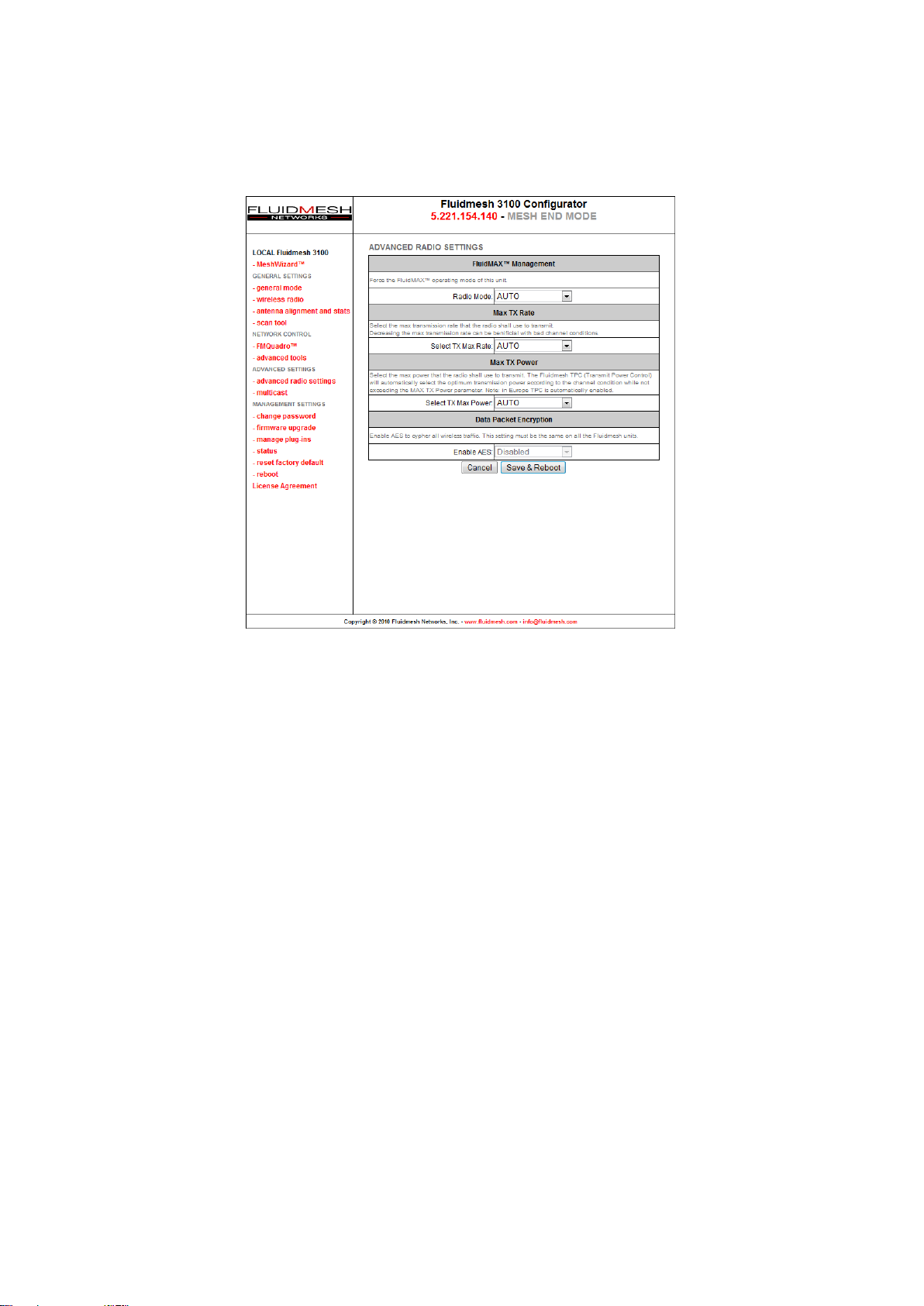
Figure 7.7: Advanced wireless parameters configuration.
Data Packet Encryption (Software Plug-in Required). Advanced Encryption Standard (AES) 128 bit encryption can be enabled at the link-level
for wireless data transmission. This feature is available in addition to the
default Fluidmesh proprietary encoding algorithm for maximum industrygrade network security. A software Plug-in is required to activate this option. Please contact your Fluidmesh Networks’ representative for details.
7.9 Antenna Alignment Tools and Physical Statistics
The antenna alignment and stats page provides a powerful tool which
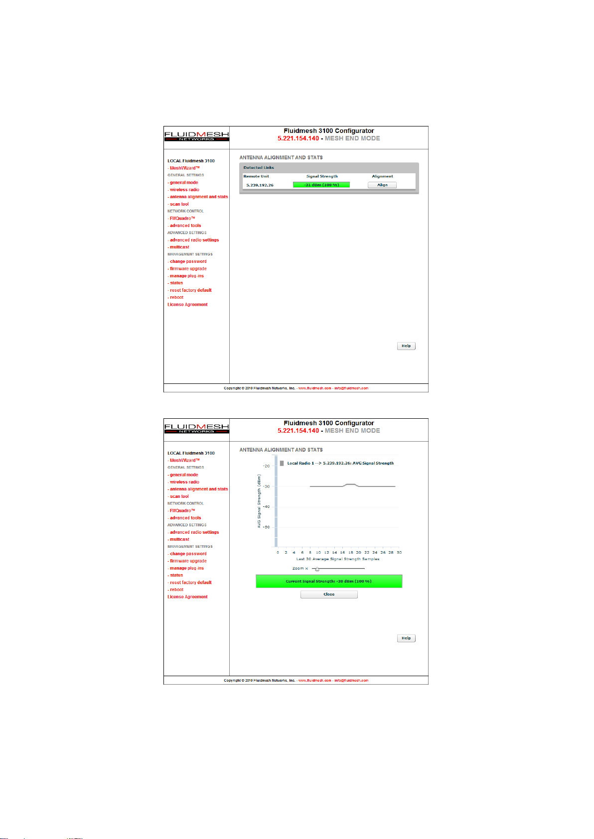
can be used to check the current link status during the normal unit operation and the physical installation of the antennas. Specifically, the web
page shows the list of links detected by the local unit and the relative signal
strengths (in dBm) on each radio as shown in Fig. 7.8(a).
To perform an accurate antenna alignment for a specific link, click on the
“Align” button to open the antenna alignment tool as depicted in Fig. 7.8(b).
43
Page 46
(a) Link selection
(b) Alignment
Figure 7.8: Antenna Alignment tool.
44
Page 47
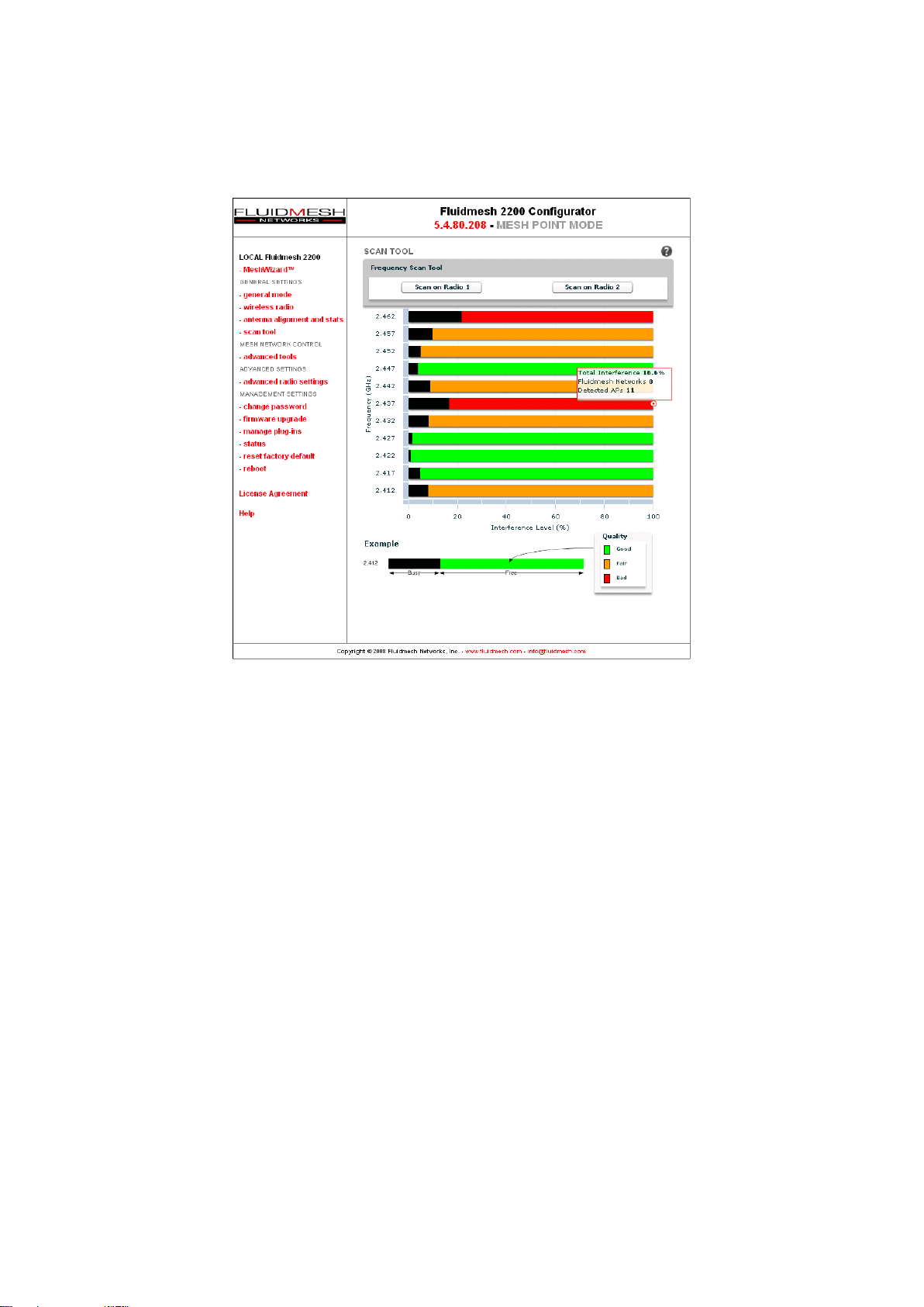
Figure 7.9: Frequency Scan Tool results.
The user is warned that the proprietary Fluidmesh TPC algorithm (see Section 7.8) will be disabled during the alignment process so as to avoid unwanted interactions with the tools. The antenna alignment tool consists of
a real-time graph and a bar which report the average signal strength and
the current signal strength detected at the local unit receiver, respectively.
During the physical antenna alignment process, the graph and the bar can
be monitored to obtain optimal link quality.
7.10 Frequency Scan Tool
The Scan Tool page provides a powerful tool for analyzing the status of
the radio interference in the available channels. The channel scan can be
started on each radio separately by means of the buttons at the top of the
page (see Fig. 7.9). As soon as the scanning is complete, a bar chart will
appear indicating the current interference level and the overall quality of
each channel.
45
Page 48

As shown in Fig. 7.9, each bar in the chart consists of two sections. The
black section represents the amount of interference detected in the channel, whereas the colored one gives a qualitative idea of the status of the
channel according to the following table:
Color Channel Quality
GREEN GOOD
YELLOW FAIR
RED BAD
Additional information such as number of Fluidmesh units and access points
detected is available by bringing the cursor of the mouse over the frequency
channel bars. Please note that in a network with overlapping channels, the
number of Fluidmesh units detected by the scan tool might be higher than
the actual number of units deployed.
46
Page 49
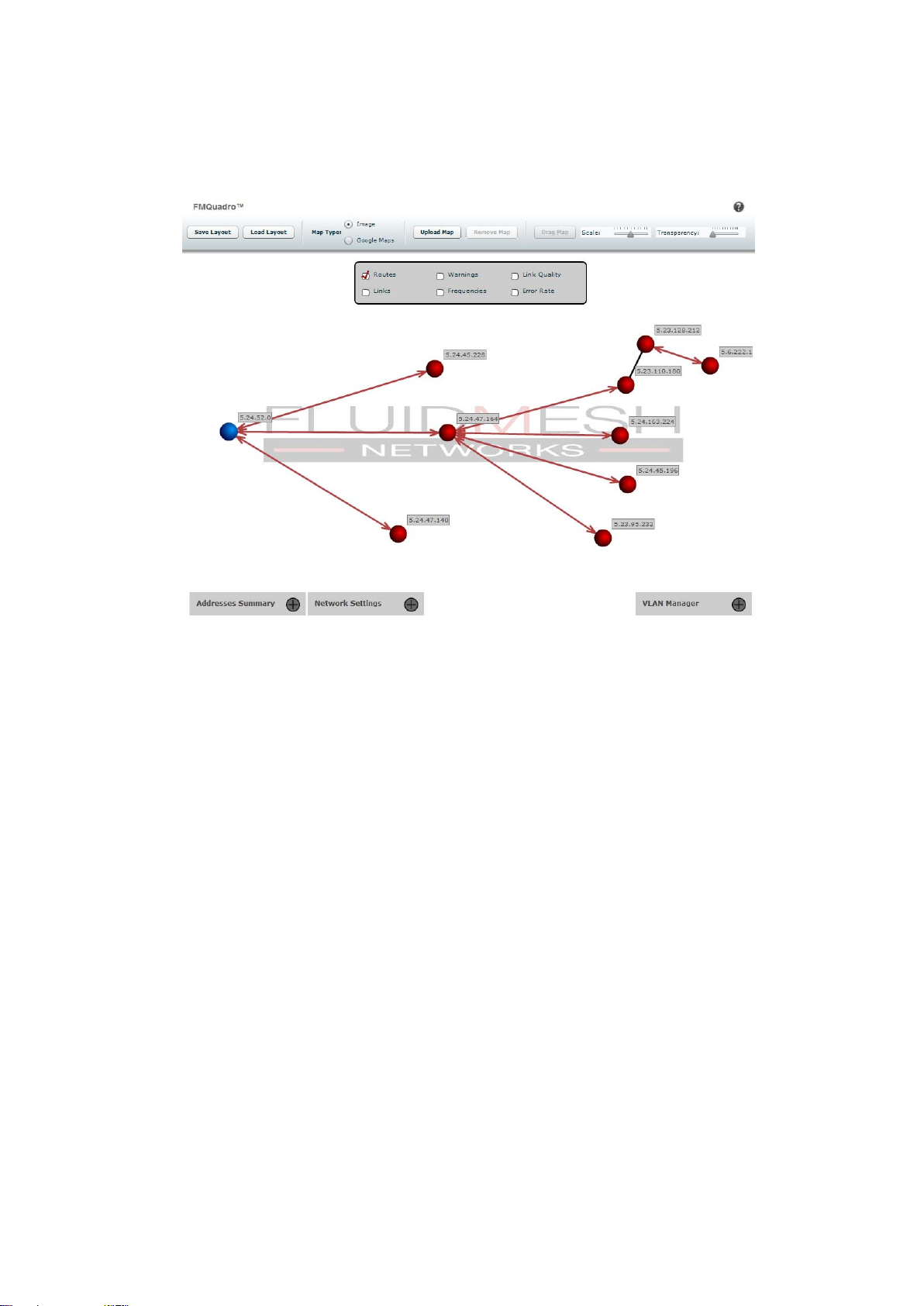
Figure 7.10: FMQuadro.
7.11 FMQuadro™ (Mesh End only)
This feature is available only in FM units configured in Mesh End mode. The
innovative FMQuadro engine provides an interactive graph representation
of the Fluidmesh network where vertices and edges represent FM units
and wireless links, respectively, as shown in Fig. 7.10. The links which are
currently in use by every packet generated/relayed by a Fluidmesh device
to reach a possible destination in the network (i.e., the routing table) are
depicted as a continuous lines.
Backup links are depicted as dashed lines, and they are not shown by default. Backup links can be viewed by selecting the appropriate field in the
top panel of the FMQuadro window.
This panel also includes other fields which can be selected to display additional always-on link information such as the link frequency, the link error
rate, and the link quality.
47
Page 50
In the graph, blue is the color of a mesh end whereas mesh points are depicted in red. The unit color becomes yellow if any anomalous condition is
detected on the unit.
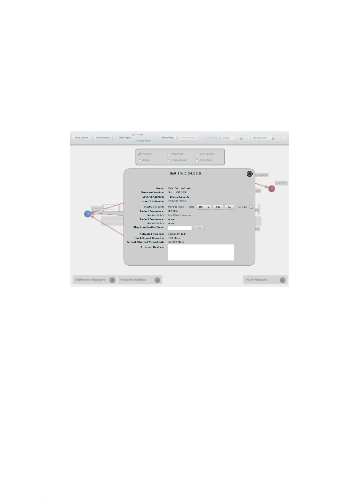
Each element displayed in FMQuadro is interactive, and can be dragged
and/or clicked to get additional real-time information based on the context.
Figure 7.11: FMQuadro. Unit information.
For example, by clicking on a specific unit, information about the remote
unit selected is displayed in a callout as shown in Fig. 7.11. This information includes the Layer 2 IP address, current FluidMAX status of the unit,
the radio frequencies currently in use, and the details of the data traffic
flows generated by the edge devices connected to the unit.
The list of currently active Plug-ins is visible. Furthermore, any Plug-in Activation Code can be conveniently added to the specific remote unit using
the form available in the callout. Finally, current throughput and maximum
capacity of the Ethernet port is reported in order to monitor the Ethernet
ports utilization and detect whether the Ethernet port is over-utilized with
respect to the installed FluidThrottle Plug-in.
Similarly, the status of a wireless link connecting any two units can be mon-
48
Page 51

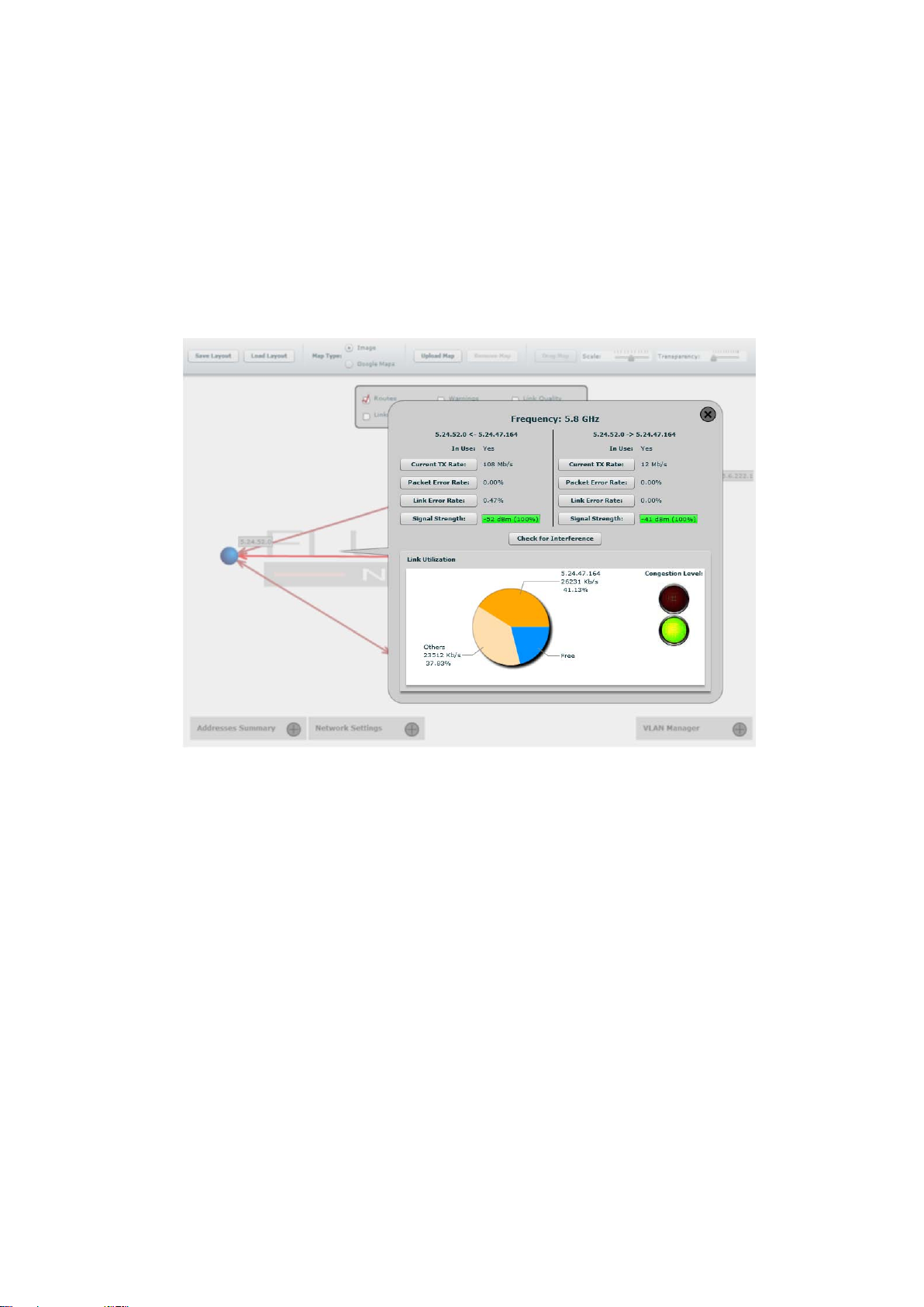
itored by clicking on the related line, as reported in Fig. 7.12. Several realtime parameters are displayed including the current signal strength, the
packet error rate, and the link utilization of both link directions (i.e. the link
from a unit to the other and vice-versa). Additionally, the current congestion
level of the link is monitored. A detailed description of the available parameters is reported in Table 7.3. Visual alarms and warnings are triggered
whenever anomalous conditions are detected, as described in Table 7.4.
Warnings are of two types: link and unit. When unit warnings are triggered, the unit color becomes yellow. The warning details are available by
clicking on the unit element. The link warnings notification can be disabled
by removing the “Warning” flag in the FMQuadro top panel.
Metric Description
Current TX Rate Current link transmission rate in Mb/s.
Packet Error Rate Percentage of packet dropped due to excessive trans-
mission errors.
Link Error Rate Percentage of packet retransmissions due to trans-
mission errors.
Signal Strength Current received signal level in dBm.
Link Utilization Percentage of the current link utilization for data
transmission in a pie chart format.
Table 7.3: Link metrics description.
Warning Type Cause
Low Signal Strength Link Link Signal Strength < 60%.
High Error Rate Link Packet Error Rate > 5%.
High Link Congestion Link Link Utilization > 80%.
Ethernet Capacity Overflow Unit Plug-in capacity exceeded.
Hidden Terminal Detected Unit Hidden terminal detected by the
FluidMAX engine.
Table 7.4: FMQuadro warning description.
Through the link status callout, the user can also check the level of interference of the selected link by clicking on the “Check for Interference” button.
The link interference is analyzed on both sides of the link by the FMQuadro
engine and the interface suggests, in case of detected problems, a set of
preferred channel frequencies that the radio link is recommended to be set
to.
All the link metrics are continuously monitored by the FMQuadro engine
49
Page 52
and statistics are logged and can be displayed by clicking on any link metric button, as shown in Fig. 7.13. By default, the last 48 hour’s statistics
are recorded with a metrics’ sampling interval of 5 minutes. The statistics
recording time can be increased up to 24 days at the cost of increasing the
metrics’s sample interval proportionally.
Figure 7.12: FMQuadro. Link information.
A table, placed at the bottom of the window, reports the network units’ address summary and can be viewed by clicking on the proper button as reported in Fig. 7.14. It is possible to assign a name to each of the Fluidmesh
units. This may be especially convenient with a large mesh network.
Furthermore, through the “Network Settings” table, placed at the bottom of
the window, you can check whether the DFS settings are consistent the
network, e.g., the DFS is enabled in the all the units. The Network Settings
table allows for harmonizing the DFS settings in the whole network with a
single mouse click.
FMQuadro is an accurate representation of the network, so it can be use-
50
Page 53
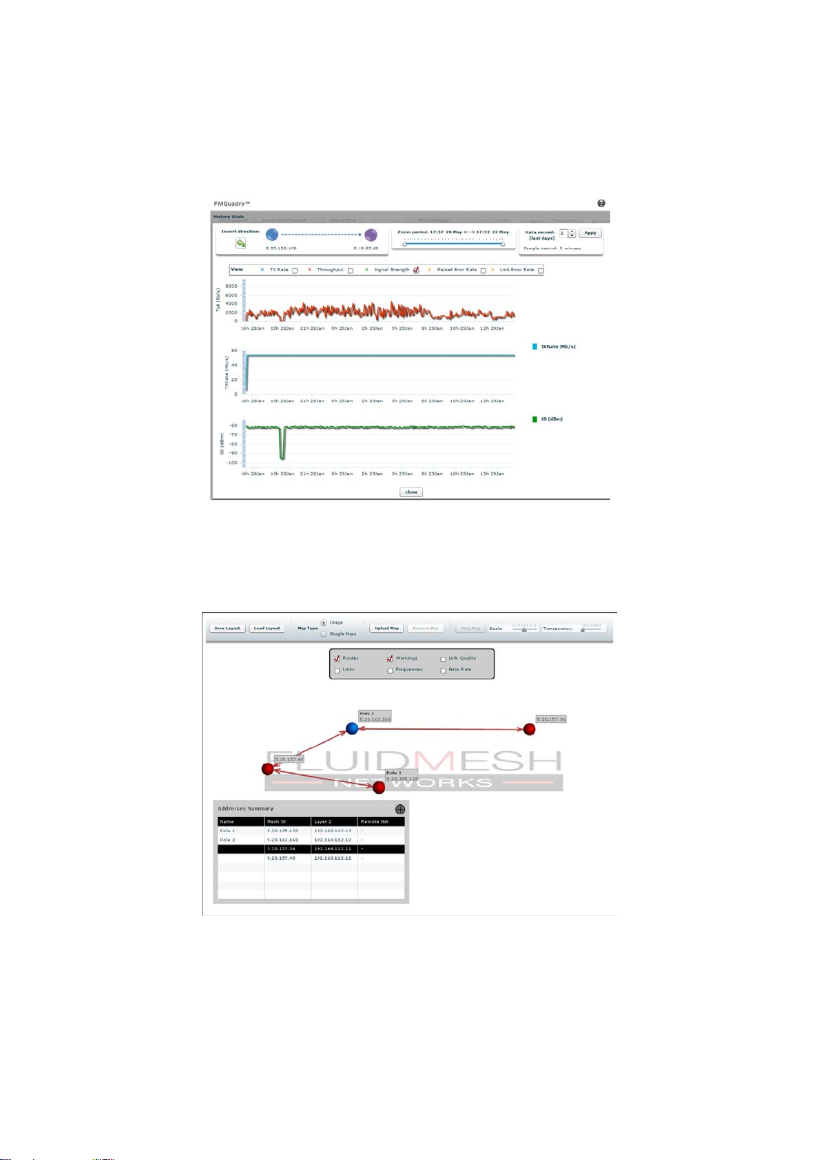
Figure 7.13: FMQuadro. Last 48 hours Link information.
Figure 7.14: FMQuadro. Addresses Summary table.
51
Page 54

ful to add a map of the area in which the Fluidmesh system is deployed.
Map images can be uploaded to the Mesh End unit using the proper button
placed in the FMQuadro top toolbar. Common image formats are supported
including png, jpg and bmp. Furthermore, whenever an Internet connection
is available to the user PC used to configure the Fluidmesh network, Google
Maps map can be used to set the background of FMQuadro.3The top toolbar provides several intuitive buttons to drag & drop the background map
and control its transparency and scale. Once the map is set up, the FM
units can be dragged to their actual installation places. Finally, the modified
layout can be saved and used again in the future.
As the FMQuadro engine collects statistics from the entire network through
the Mesh End unit, it is no longer necessary to directly connect to remote
units. The overall network status and individual device status can be monitored real-time through the FMQuadro interface on Mesh End unit.
2
Aerial images can be downloaded using Google Earth (http://earth.google.com/).
3
Please note the you need an Internet connection to use the Google Maps background
feature.
2
52
Page 55
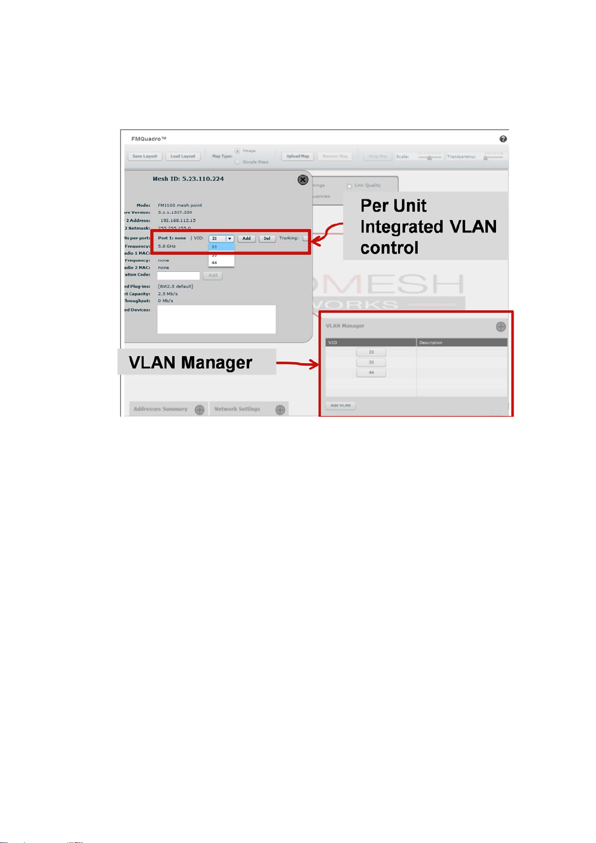
Figure 7.15: VLAN configuration steps.
7.11.1 VLAN Tagging Configuration (Software Plug-in Required)
Each VLAN can be configured via FMQuadro with a simple two steps procedure as described below. Please note that VLANs require some network
configuration expertise and should be used by advanced users only. Please
refer to Section 5.2.1 for further details.
1. VLAN ID creation: a new VID can be created using the VLAN man-
ager control placed at the bottom-right hand of the FMQuadro window
as shown in Fig. 7.15. You must specify the VID number and, optionally, a description of the VLAN. Once the VID is created you can
specify the Ethernet ports and/or the MAC addresses membership.
2. Ports and/or MAC membership: FM unit ethernet ports can be
added to the created VLAN by using the specific callout of the unit
as shown in Fig. 7.15. On the other hand, MAC addresses membership can be specified in the VLAN manager control.
53
Page 56

The Fluidmesh VLAN implementation is compatible with the specification
of the IEEE 802.1q standard and, thus, the Fluidmesh network can interoperate with other VLAN-aware network devices. VLAN trunking between
the Fluidmesh network and Ethernet switches is also supported and can
be enabled by selecting the proper control in the unit’s callout window. Enabling VLAN trunking on a specific port instructs the FM unit to forward
VLAN membership information to the device connected to the port, thus
extending VLANs across multiple network devices.
To simplify the configuration of the units when trunking is enabled, a special
VID #1 is available. Simply configuring the network switch with a VLAN #1
will allow any PC belonging to the VLAN #1 to access the web interface of
the FM units without the need for additional settings of the FM units.
7.12 Firmware Upgrade
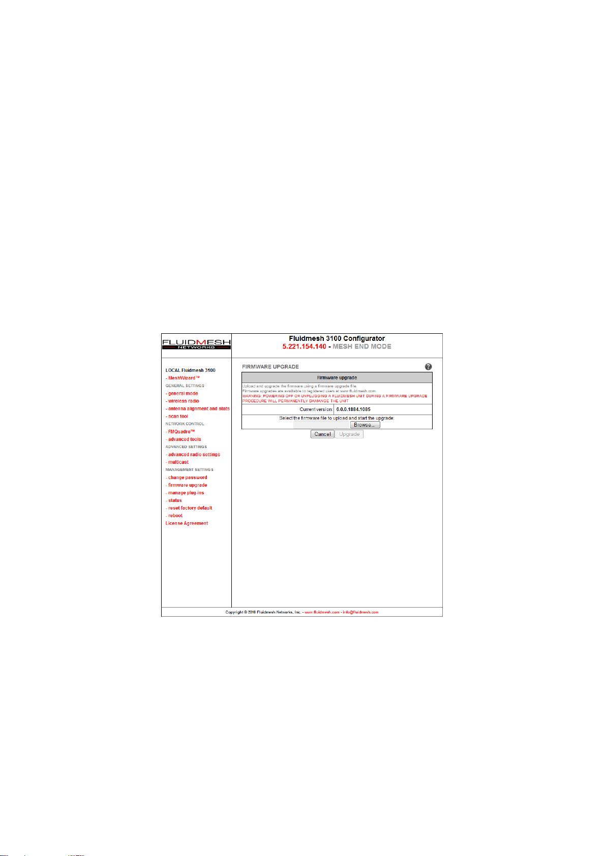
Through the firmware upgrade page (Fig. 7.16), it is possible to upgrade
the Firmware of the devices to the latest version available. To do so, download the latest Firmware upgrade file to your PC from the Fluidmesh Networks Web site at www.fluidmesh.com.4Select the correct file on your hard
disk, and upload it. This operation might take several minutes. The unit will
automatically reboot at the end of the upgrade process.
Upgrading a working system is always a delicate and somewhat risky operation. Fluidmesh discourages anybody from upgrading a functional system
except if there is an issue to fix.
Recommended upgrading procedure for running systems:
1. Download the latest firmware release available for your hardware/firmware
family;
2. Power off the whole network;
3. Power on one device at a time;
4. Connect directly to the Fluidmesh unit to be upgraded directly through
an Ethernet cable;
5. Write down the unit configuration (at least network settings and wireless settings);
4
An approved Fluidmesh extranet account is required. Please register for a an on-line
account and contact Fluidmesh for approval.
54
Page 57
6. Upgrade the device with the chosen firmware;
7. Once the upgrade is completed, wait for the system to reboot;
WARNING: DO NOT RESTART OR POWER OFF THE UNIT WHILE UPGRADING THE FIRMWARE. RESTARTING OR POWERING OFF THE
UNIT BEFORE THE UPGRADE IS COMPLETED MIGHT DAMAGE THE
UNIT.
When the upgrade is completed, check the firmware upgrade page in
order to make sure that the new firmware version has been correctly updated. If the firmware version has not been changed, the upgrade process
has failed. Therefore, please repeat the upgrading procedure from the beginning.
Figure 7.16: Firmware upgrade Web page.
55
Page 58
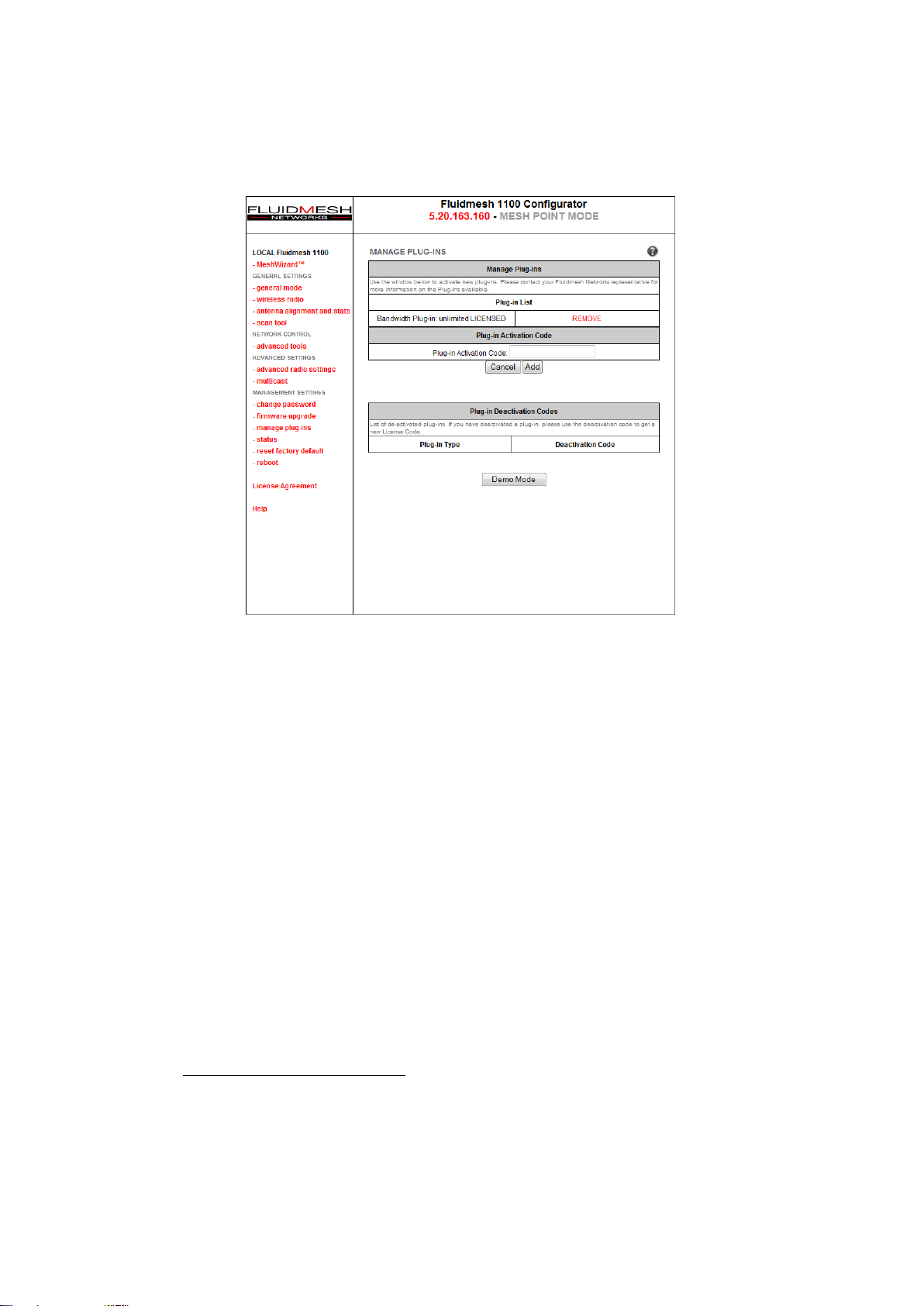
Figure 7.17: Plug-ins management Web page.
7.13 Plug-in Management
The manage plug-ins page (Fig. 7.17) shows the installed Plug-ins and
allows the user to add Plug-in Activation Codes. Additionally, a Plug-in can
be deactivated to, for example, transfer it from one unit to another. Once the
Plug-in has been deactivated, you will be provided with a Deactivation Code
displayed at the bottom of the page. In order to get a fresh Activation Code
to use it in another device, you must complete the unit deactivation procedure at the Fluidmesh Networks website (www.fluidmesh.com). Please
refer to Section 6 for details on the software Plug-in activation/deactivation
procedures.
A 8 hour plug-in trial is available by clicking on the “Demo Mode” button at
the bottom of the page. The plug-in demo mode includes the 4.9 GHz5, the
AES and the Unlimited plug-in trials all at once. The unit will reboot on the
8 hours plug-in trial expiration.
5
Not available in Brazil.
56
Page 59
7.14 Advanced Tools
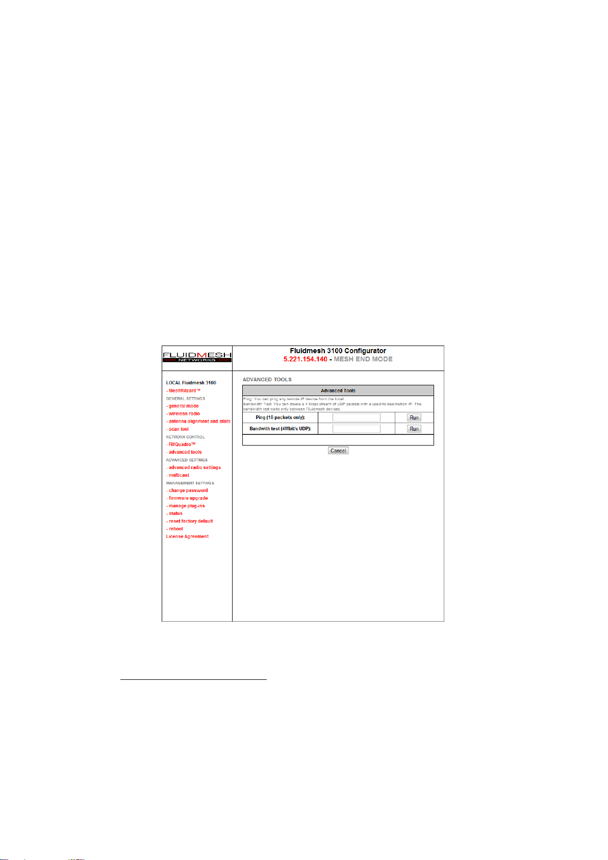
Through the advanced tools page, it is possible to run tests to verify network connectivity and the achievable throughput on a network path. As
shown in Fig. 7.18, network connectivity can be tested by issuing a “Ping
Test” towards a specific destination. Additionally, the “Bandwidth Test” tool
generates a stream of packets at a specified rate to test the available network path throughput.
In order to run a Ping or a Bandwidth Test, write the destination IP in the
proper window and click run. The Bandwidth Test allows you to select the
throughput from a value of 4Mb/s to 20 Mb/s. Both tests can be run on
top of a loaded network to test operational performances, or on top of an
unloaded network to test installed capacity.
6
Figure 7.18: Advanced Tools Web page.
6
Please note that the achievable rate computation is cpu-intensive and only indicative.
Results may be not accurate. Usually the bandwidth tests tend to underestimate the real
throughput of the link.
57
Page 60
7.15 Multicast
By default, FM units operating in Mesh Point mode forward all the multicast
traffic generated by the cameras to their closest Mesh End unit. However,
in some network configurations, it may be convenient to forward the multicast traffic from a Mesh Point to others, e.g., to remotely record the video
flow.
By default, the unit operating in Mesh End mode does NOT forward any
multicast traffic7to the wireless networks.
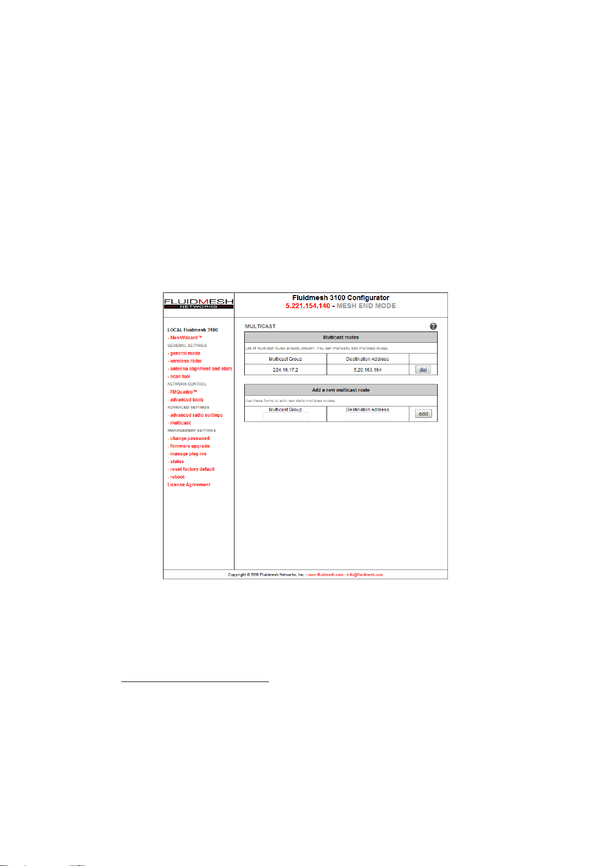
Figure 7.19: Add/Remove multicast routes towards Mesh Points.
To redirect a traffic flow to a Mesh Point, you must specify all the multicast
flows redirection information within the Mesh End multicast page as shown
in Fig 7.19.
7
With the exception of UPnP and IGMP traffic.
58
Page 61
7.16 PoE Passthrough (FM1100 and FM1200 only)
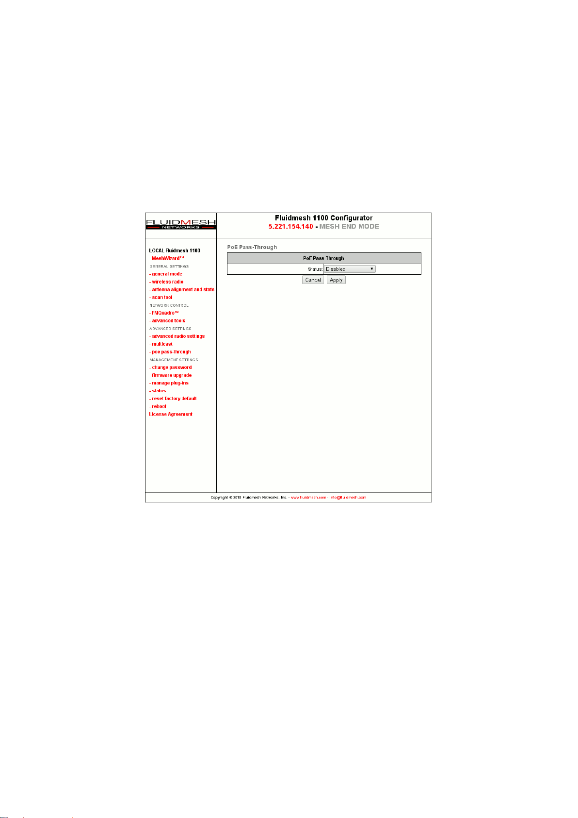
The second Ethernet port present on the FM1100 and FM1200 can be used
to power up other passive 12-18 V PoE devices such as cameras and
FM units. This feature can be enabled through the PoE passthrough
page as depicted in Fig. 7.20.
Figure 7.20: Enable the PoE passthrough feature.
7.17 Change Password
Use this page to change the password to access the unit Web GUI.
7.18 Status
This page reportsasummary of the status of the unit. Additionally, in case
of system malfunctions, the unit’s diagnostic file dump can be downloaded
59
Page 62

through this page and emailed to the Fluidmesh technical support to facilitate the problem diagnosis.
7.19 Reboot and Reset to Factory Default
Use the Reboot page to restart the unit. Use the Reset to Factory Default
page to restore the unit default factory settings.
7.20 On-line Help
The electronic version of this manual is available by accessing the Help web
page. Additionally, specific manual sections can be consulted by clicking
on the question mark present at the upper right corner of every page of the
Web GUI.
60
Page 63

8 Troubleshooting
The troubleshooting section will allow you to solve the most common problems encountered when configuring and installing Fludimesh products.
8.1 I am unable to get the log-in screen
If you are unable to get the log-in form on your computer screen, you should
check the following:
Is your computer set to a valid IP address? You should manually set the
correct network settings as follows:
1. In Windows Explorer, right-click “My Network Places” and select Prop-
erties.
2. Right-click Local Area Network and select Properties.
3. Right-click Internet Protocol (TCP/IP) and select Properties.
4. Set the IP address to 192.168.0.30 (or any other IP address belonging
to the subnet 192.168.0.0/255.255.255.0), Netmask to 255.255.255.0.
5. Click OK, then OK again.
Have you disabled the “Access the Internet using a proxy server” function?
To disable the Access the Internet using a proxy server function, go to
Control Panel > Internet Options > Connections > LAN Settings and
uncheck the enable box.
8.2 I am unable to log-in into the Web-based interface
If you are unable to log-in into the Web-based interface, check your user
name and password settings.
The user name cannot be changed by the user and corresponds to:
61
Page 64

admin
The password can be changed, so make sure you are using the right password. The default password is:
admin
If you forgot the password, check Section 8.3 to fix the problem.
8.3 I forgot the administrator password
If you forgot the password and need to access the Web-based interface,
you must physically access the unit, open the enclosure in a weather-safe
situation and reset to the factory default settings. Please refer to the instructions of Section 3.1.4 for FM1100,
3.2.4 for FM3100 units.
Section 3.3.4 for FM1200 and Section
8.4 In Bridge Mode I get no Link or the Link LED is
always red or I am getting a weak Wireless link
(below 60% signal strength)
To improve your link strength, please check the following:
• Antenna Alignment: the two antennas must be aligned toward each
other.
• Line of Sight: you must have clear line of sight between the two
antennas.
• Antenna Polarization: both antennas must have the same polariza-
tion. Check antenna polarity.
wer: check if the FM unit is properly powered-on with the provided
• Po
PoE injector.
• Channel: both FM unit units must be operating on the same channel.
62
Page 65
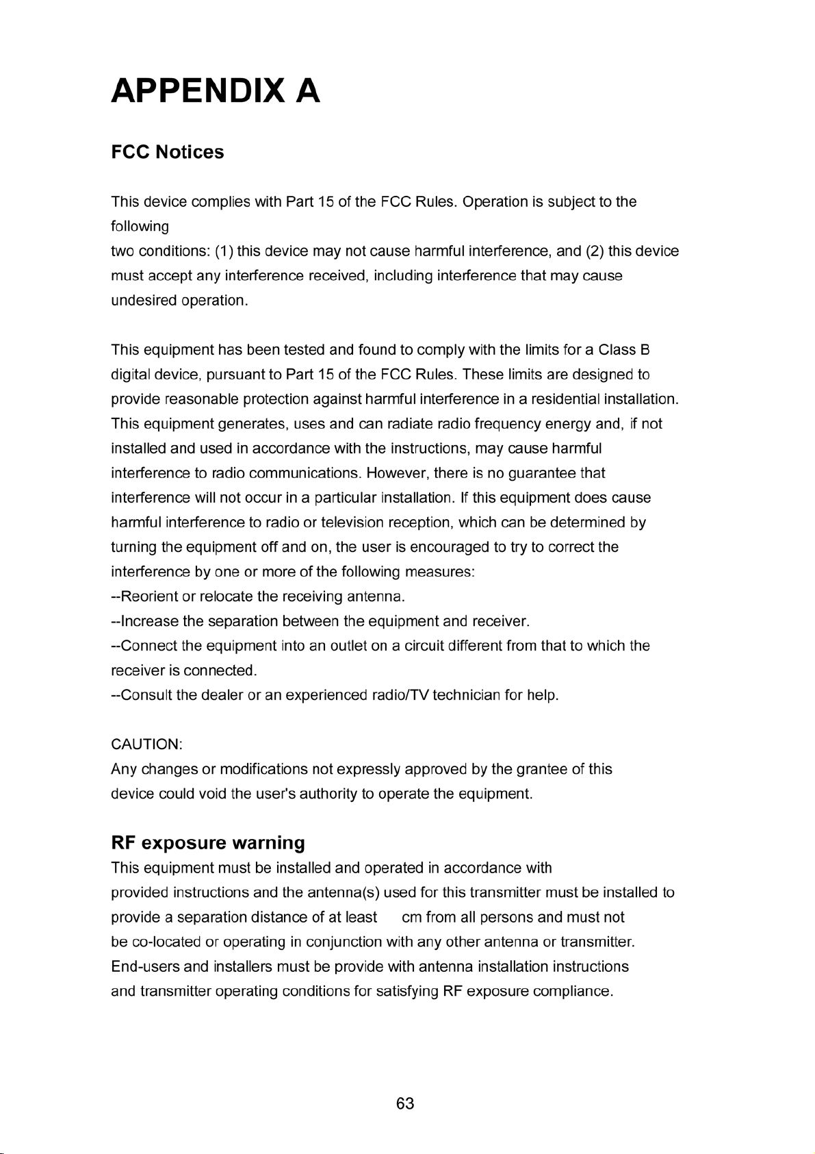
APPENDIX A
FCC Notices
This device complies with Part 15 of the FCC Rules. Operation is subject to the following
two conditions: (1) this device may not cause harmful interference, and (2) this device
must accept any interference received, including interference that may cause undesired
operation.
CAUTION: Change or modification not expressly approved by the party responsible
for compliance could void the user’s authority to operate this equipment.
This equipment has been tested and
digital device, pursuant to Part 15 of the FCC Rules. These limits are designed to provide
reasonable protection against harmful interference in a residential installation. This
equipment generates, uses and can radiate radio frequency energy and, if not installed
and used in accordance with the instructions, may cause harmful interference to radio
communications. However, there is no guarantee that interference will not occur in a
particular in
television reception, which can be determined by turning the equipment off and on, the
user is encouraged to try to correct the interference by one or more of the following
measures:
--Reorient or relocate the receiving antenna.
--Increase the separation between the equipment and receiver.
--Connect the equipment into an outlet on a circuit different from that to which the receiver
is connected.
--Consult the dealer or an experienced radio/TV
CAUTION:
Any changes or modifications not expressly approved
stallation. If this equipment does cause harmful interference to radio o
found to comply with the limits for a Cl
technician for help.
by the grantee of this device could
ass B
r
void the user's authority to operate the equipment.
RF exposure warning:
The equipment complies with FCC RF exposure limits set forth for an uncontrolled
environment. The equipment must not be co-located or operating in conjunction with any
other antenna or transmitter.
40
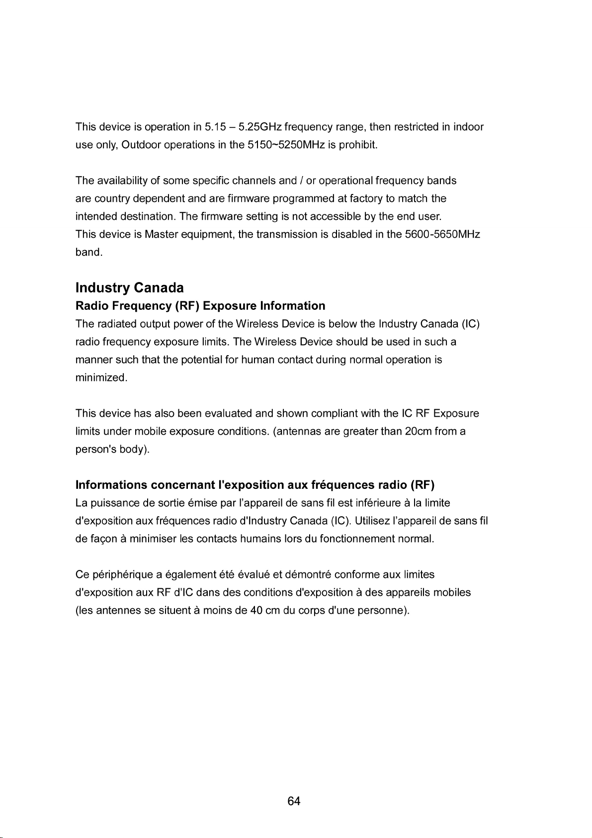
This device is operation in 5.15 – 5.25GHz frequency range, then restricted in
indoor use only, Outdoor operations in the 5150~5250MHz is prohibit.
63
Page 66
Page 67

APPENDIX C
Contact Information
Worldwide Headquarters
Fluidmesh Networks, LLC
1359 Barclay Boulevard
Buffalo Grove, IL 60089
U.S.A.
Tel. +1 (617) 209 -6080
Fax. +1 (866) 458-1522
EMEA Headquarters (Italy)
Tel. +39 02 0061 6189
65
UK Branch
Tel. +44 2078 553 132
www.fluidmesh.com
Page 68

Page 69

Page 70

Page 71

Worldwide Headquarters
Fluidmesh Networks, LLC
1359 Barclay Boulevard
Buffalo Grove, IL 60089
U.S.A.
Tel. +1 (617) 209 -6080
Fax. +1 (866) 458-1522
EMEA Headquarters (Italy)
Tel. +39 02 0061 6189
UK Branch
Tel. +44 2078 553 132
www.fluidmesh.com
 Loading...