

Fluidmesh FM 1200 volo Installation Instructions Manual
FM 1200 VOLO
Physical
Installation
WIRELESS BACKHAULING WITH DOUBLE THE POWER
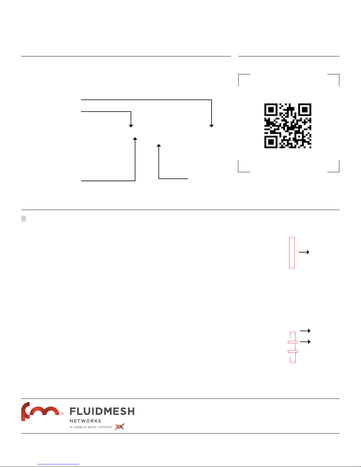
PRODUCT DESCRIPTION
LED panel
Reset Button
Main Ethernet Port
1
(LAN 1)
For poe and data
Secondary
Ethernet Port
(LAN 2)
For data only
Instructions
View our online manual here.
Ver nuestro manual en línea aquí.
Voir notre manuel en ligne ici.
Visualizza il nostro manuale on-line qui.
MOUNTING
Mount the FM1200 as indicated in the drawing with the Ethernet ports pointing down.
Use plastic or metal tie wraps to install on a
pole. Leave some slack to allow movement
for proper alignment.
Align the FM1200. In order for the link to
work, the unit needs to be pointing toward
the FM1200 on the other end. Clear line of
sight is required
MONTE
Monte el FM1200 como se indica en el dibujo anterior con los puertos Ethernet apuntando hacia abajo. Utilice sunchos plásticos
o de metal para instalar en postes. Sujételo
permitiendo el movimiento necesario para
la alineación.
Alinee el FM1200. Para que el enlace funcione, la unidad debe estar apuntando hacia el
FM1200 en el otro extremo. Una clara línea
de visión es necesaria.
MONTEZ MONTARE
Montez le FM1200 comme indiqué sur le
schéma ci-dessus, les ports Ethernet orientés vers le bas. Utilisez des colliers en métal
ou en plastique pour le montage sur un poteau. Laissez un peu de jeu pour permettre
les mouvements d’alignement.
Alignez le FM1200. Pour que la liaison
fonctionne, l’appareil doit pointer vers le
FM1200 à l’autre xtrémité. Aucun obstacle
ne doit interférer.
Montare il FM1200 con le porte Ethernet
verso il basso, come indicato nella figura
sopra. Utilizzare fascette di plastica o metallo per installarlo su un palo. Lasciarlo leggermente allentato per muoverlo e allinearlo in modo appropriato.
Allineare il FM1200. Per fare in modo che il
link funzioni, le unità devono essere posizionate verso il FM1200, ma dalla parte opposta. E’ richiesta visibilità ottica.
Pole Diameter
1.5” - 3.5” | 38mm - 89mm
POLE
POLE
Plastic or metal
tie wraps
HEADQUARTERS.
1327 BARCLAY BOULEVARD
BUFFALO GROVE,
IL, 60089, U.S.A.
TELEPHONE.
+1.617.209.6080
FAX .
+1.866.458.1522
EMAIL.
INFO@FLUIDMESH.COM
WEB.
FLUIDMESH.COM
P-01
2
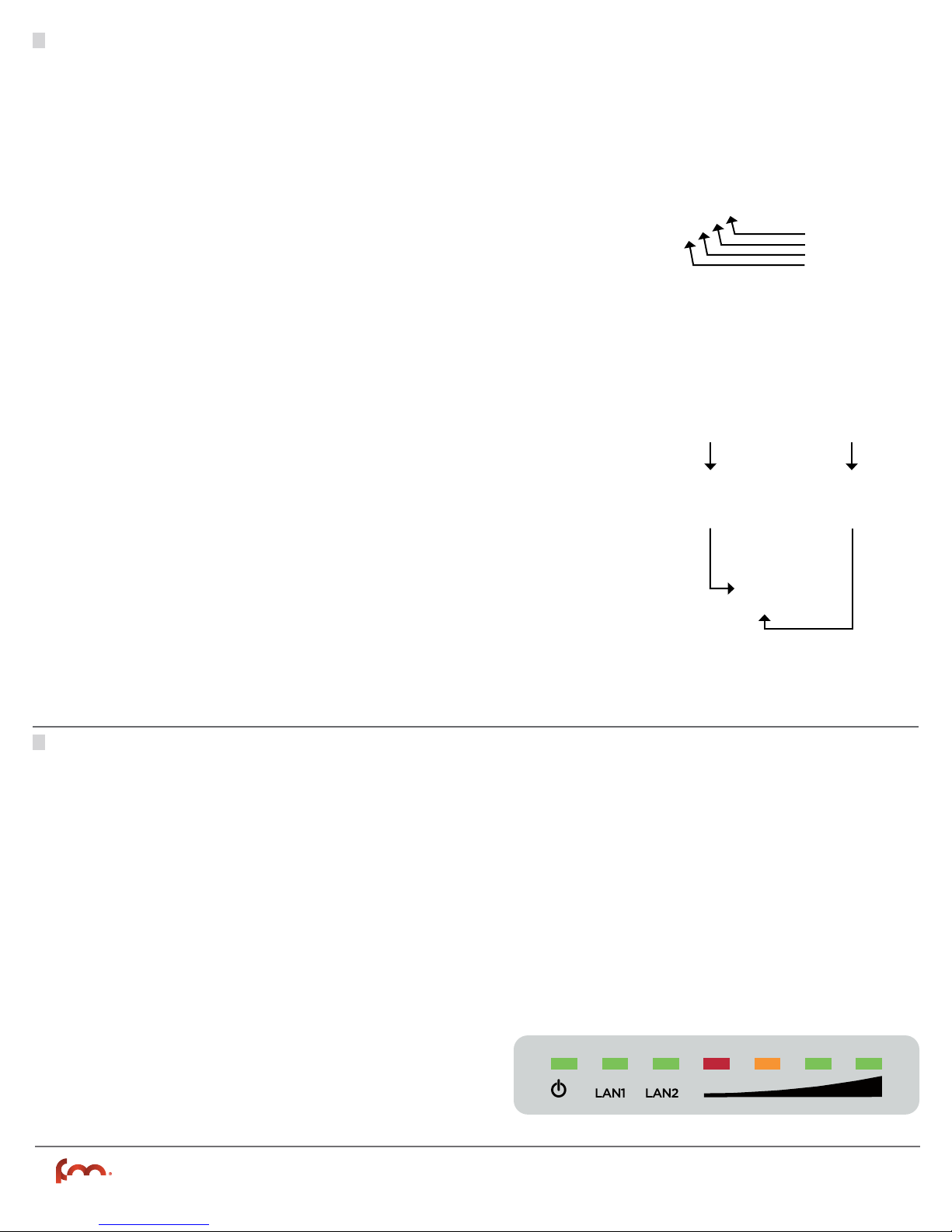
WIRING CABLEADO
Plug-in the CAT5/6 shielded cable as indicated
in the drawing. To facilitate installation, VOLO
has a two cord watertight cable gland with a
standard NPT-1 thread so you can run pre-made
CAT5/6 shielded cables or conduit directly to
the radio. Make sure the connection is solid.
Close the panel on the back of the unit.
Use the POE Injector to power up the FM1200
VOLO unit as described in the picture. Cables
CAT5/6 STP are recommended. Make sure to
use shielded cables and connectors! WARNING: MAX cable length from FM1200 VOLO to
IP camera / switch = 300 feet and the MAX
cable length from FM12000 VOLO to the provided PoE = 60 ft. Use only the provided PoE
injector, as other PoE injectors may not work.
Enchufe el cable CAT5 / 6 blindado como se
indica en el dibujo. Para facilitar la instalación,
VOLO tiene un cable estanco glándula de cable de dos con un NPT-1 rosca estándar para
que pueda ejecutar pre-hechas CAT5 / 6 cables apantallados o conducto directamente a la
radio. Asegúrese de que la conexión es sólido.
Cierre el panel de la par te posterior de la unidad .
Utilice el inyector PoE para encender la unidad
FM1200 VOLO como se describe en la imagen
(izquierda). Se recomiendan cables CAT5/6 STP.
Asegúrese de utilizar cables y conectores blindados! ADVERTENCIA: MAX longitud del cable desde FM1200 VOLO a la cámara IP / interruptor = 90
metros y la longitud máxima del cable de FM12000
VOLO a la proporcionada PoE = 18 metros. Utilice
sólo el proporcionado inyector PoE, como otros inyectores PoE pueden no funcionar.
Washer
Inner cable grand
Optional gromet
Outer cable gland
CÂBLAGE
Branchez le câble CAT5 / 6 blindé comme indiqué dans le dessin. Pour faciliter l’installation,
VOLO dispose d’un presse-étoupe étanche de
deux cordon avec un NPT-1 filetage standard de
sorte que vous pouvez exécuter pré-faites CAT5
/ 6 câbles blindés ou conduit directement à la
radio. Assurez-vous que la connexion est solide.
Fermez le panneau sur l’ arrière de l’appareil.
Utilisez l’injecteur PoE pour alimenter l’unité FM1200 VOLO comme décrit dans le
tableau. Il est recommandé d’utiliser des
câbles CAT5/6 STP. Assurez-vous d’utiliser
des câbles blindés et des connecteurs! ATTENTION: longueur maximale du câble de FM1200
VOLO à la caméra IP / switch = 90 mètres et la
longueur maximale du câble de FM12000 VOLO
aux PoE = mètres 18ft fournis. Utilisez uniquement la condition injecteur PoE, que d’autres
injecteurs PoE peuvent ne pas fonctionner.
CABLAGGIO
Plug-in del cavo CAT5 / 6 schermato, come indicato nel disegno. Per facilitare l’installazione,
Volo ha un cavo a tenuta stagna ghiandola due
cavi con un NPT-1 filettatura standard in modo
da poter eseguire pre-fatte CAT5 / 6 cavi
schermati o condotto direttamente alla radio.
Assicurarsi che la connessione è solido. Chiudere il pannello sul retro dell’unità.
Utilizzare l’iniettore PoE per alimentare l’unità FM1200 VOLO, come descritto nella foto
(a sinistra). E’ raccomandato l’utilizzo di cavi
CAT5/6 STP. Assicurarsi di utilizzare cavi e connettori schermati! AVVERTENZA: Lunghezza
massima del cavo dal FM1200 VOLO alla telecamera IP / switch = 90 metri e la lunghezza
massima del cavo da FM12000 VOLO alle PoE
previste = metri 18. Usare solo il previsto iniettore PoE, come altri iniettori PoE potrebbero
non funzionare.
3
LEDs
The seven (7) LEDs can be used to check the unit
and the link quality status. From the left-hand
side, the first three green LEDs indicate the unit
power, the Main Ethernet (LAN1) port activity, the
Secondary Ethernet (LAN2) port activity respectively. The remaining 4 colored LEDs indicate the
level of the link signal and can be used for antenna
alignment purposes. During the unit boot-up process, the LEDs indicate the boot status and can
be used for problem detection. In fact, the LEDs
light up in sequence from the leftmost one (red)
to rightmost one (bright green). Please refer to
the User’s Manual for more details.
LEDs
Los siete (7) LED pueden ser utilizados para
comprobar el estado de la unidad y la calidad del
enlace. Desde la izquierda, los tres primeros LEDs
verdes indican encendido, la actividad en el puerto principal de Ethernet (LAN 1) y la actividad en
el puerto secundario de Ethernet (LAN 2), respectivamente. Los 4 LEDs restantes de colores
indican el nivel de la señal de enlace y pueden ser
utilizados para la alineación de la antena. Durante
el proceso de arranque de la unidad, los LEDs indican el estado del arranque y pueden ser utilizados para detectar problemas. Por favor, consulte
el Manual del Usuario para más detalles.
LEDs
I sette (7) LEDs possono essere utilizzati per controllare l’unità e la qualità del link. Sulla parte sinistra i primi tre LEDs verdi indicano rispettivamente lo stato dell’alimentazione dell’unità, l’attività della porta Ethernet
principale (LAN1) e l’attività della seconda porta Ethernet. I quattro LED
colorati rimanenti, invece, indicano il livello del segnale del link e possono
essere utilizzati per allineare l’antenna. Durante l’accensione dell’unità i
LEDs indicano lo stato di avvio e possono essere utilizzati per individuare
eventuali problemi. Per maggiori informazioni consultare il Manuale d’uso.
SHIELDED
BLINDADO
BLINDE
SCHERMATO
SHIELDED
BLINDADO
BLINDE
SCHERMATO
LEDs
Les sept (7) leds permettent de vérifier le
fonctionnement de l’appareil et la qualité du
lien. En partant de la gauche, les trois premières leds vertes indiquent respectivement
la présence de tension, l’activité du principal
port Ethernet (LAN1) et l’activité du second
port Ethernet (LAN2). Les quatre leds colorées restantes indiquent le niveau du signal de
liaison et peuvent être utilisées pour aligner
correctement l’antenne. Pendant la séquence
de boot de l’appareil, les leds indiquent l’état
du boot et peuvent être utilisées pour la détection des problèmes. Veuillez consulter le
mode d’emploi pour plus d’informations.
Physical Installation Instructions
P-02
 Loading...