

Page 1

FlowCam
Dynamic Imaging Particle Analyzer
®
8000 Series
User Guide
Page 2

FlowCam® 8000 Series Dynamic Imaging Particle Analyzer
2 of 39
Proprietary Rights Notice
Information in this document is subject to change without notice. No part of this document may be reproduced or
transmitted in any form or by any means, electronic, mechanical or otherwise, for any purpose, without the
express written permission of Fluid Imaging Technologies. Fluid Imaging Technologies may have patents or pending
patent applications, trademarks, copyrights or other intellectual or industrial property rights covering this
document or subject matter in this document. The furnishing of this document does not give a license to these
property rights except as expressly provided in any written license agreement from Fluid Imaging Technologies.
© 2017 Fluid Imaging Technologies, Inc. All rights reserved. 11072017
FlowCam and VisualSpreadsheet are registered trademarks of Fluid Imaging Technologies, Inc. All other product
and company names and logos are trademarks of their respective holders.
Fluid Imaging Technologies
200 Enterprise Drive
Scarborough, Maine 04074 USA
fluidimaging.com
Page 3

FlowCam® 8000 Series Dynamic Imaging Particle Analyzer
3 of 39
Contents
Warnings ............................................................................................................................... 4
Laser Precautions ............................................................................................................................................. 4
Cautions ............................................................................................................................................................ 4
Safety Precautions ............................................................................................................................................ 4
Introduction .......................................................................................................................... 6
Technical Specifications .................................................................................................................................... 7
Physical Specifications ...................................................................................................................................... 7
Analyzer Components ...................................................................................................................................... 8
Overview ........................................................................................................................................................... 9
Objectives ....................................................................................................................................................... 10
Fluorescence Detection System (FlowCam 8400) .......................................................................................... 10
Welcome ............................................................................................................................. 11
Package Contents ........................................................................................................................................... 11
Choosing a Location ........................................................................................................................................ 11
Computer Peripherals..................................................................................................................................... 11
Setting Up the Analyzer ....................................................................................................... 12
Connecting Peripherals................................................................................................................................... 12
Powering on Your Analyzer ............................................................................................................................ 12
Preparing the Analyzer ........................................................................................................ 13
Checking Internal Connections ....................................................................................................................... 13
Adding Solutions ............................................................................................................................................. 13
Installing the Flow Cell .................................................................................................................................... 14
Installing the Objective Lens ........................................................................................................................... 15
Autofocusing the Flow Cell ............................................................................................................................. 17
Focusing the Flow Cell Manually .................................................................................................................... 19
Defining the Context Settings ......................................................................................................................... 22
Performing a Sample Analysis .............................................................................................. 27
Cleaning and Rinsing the Analyzer ....................................................................................... 28
Care and Maintenance......................................................................................................... 30
Appendix A: Changing the Pump Syringe .............................................................................. 31
Appendix B: Frequently Asked Questions ............................................................................. 34
Appendix C: Services ........................................................................................................... 35
Standard Factory Limited Warranty ..................................................................................... 37
Fluid Imaging Technologies FOV (Field-of-View) Flow Cell Limited Warranty ............................................... 38
Customer Support ............................................................................................................... 38
Declaration of Conformity ................................................................................................... 39
Page 4
FlowCam® 8000 Series Dynamic Imaging Particle Analyzer
4 of 39
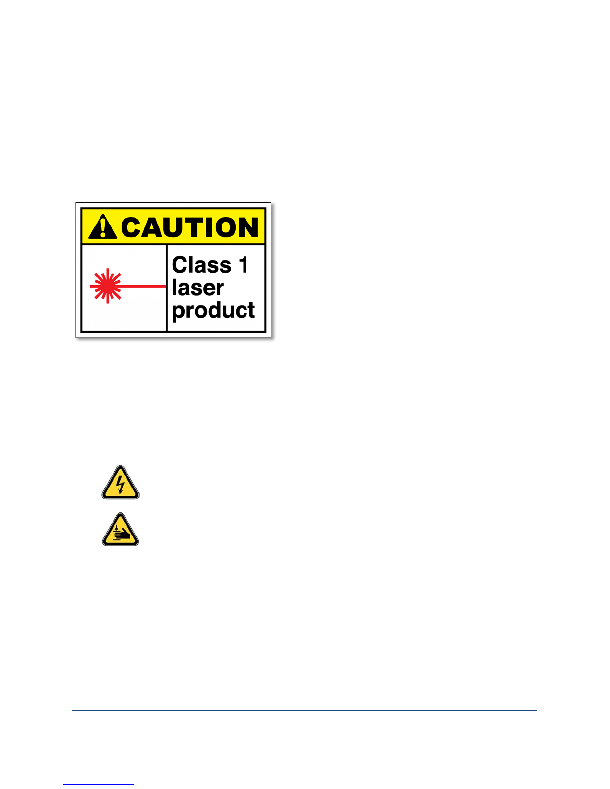
• The FlowCam 8400 analyzer contains an
Imaging Technologies.
Warnings
Before operating your FlowCam 8100 or 8400 analyzer, read this guide carefully to prevent damage to
humans, animals, integrated devices, and connected devices. Always follow local safety rules. The
instrument should be verified for safe operation following normal use, maintenance, and any factory
service activities. Failure to use this instrument in the manner specified in this guide may impair safety
features and nullify operator protection.
Laser Precautions
embedded Class 3 laser within its housing. Under
normal operating conditions, the housing and
other protective features prevent the emission of
laser light outside the analyzer. To avoid the
possibility of any laser light exposure, ensure that
you follow all operating instructions and that the
analyzer’s doors and housings remain closed
while it is operating.
• Operating the FlowCam 8400 analyzer with
protective housing or doors that are damaged or
otherwise not in good operating condition may
expose the user and others to laser radiation. If
laser light is observed or detected, discontinue
use of the product immediately and contact Fluid
Cautions
To reduce the risk of electric shock, do not remove any protective covers.
During operation of the FlowCam analyzer, the syringe pump/barrel can move
unexpectedly and without warning. Keep all body parts clear of this area.
Safety Precautions
• To reduce the risk of serious personal injury or equipment damage, never remove the inner
panels of the FlowCam analyzer.
• Beware of electrical shock hazards. To prevent the risk of electrical shock or fire, do not locate
the instrument in wet or unsafe laboratory conditions. Do not touch any damaged, non-isolated
electrical parts.
Page 5

FlowCam® 8000 Series Dynamic Imaging Particle Analyzer
5 of 39
• Use appropriate precautions to minimize and prevent the introduction of liquid into the
instrument and contact with any electrical assemblies. The instrument operates on a detachable
power supply that allows for immediate disconnect from power in the event of an emergency.
Use only the power cords provided by the manufacturer to operate the instrument and
peripheral devices.
• Mishandling may harm this instrument. Before lifting or moving the instrument, ensure that all
cords and external equipment have been properly disconnected. When moving the instrument,
always carry it with both hands. Grasp the front corner with one hand and place the other hand
under the opposite side back corner for support. Always use proper lifting techniques.
• Install the instrument in such a way as to ensure that all power cords and ventilation openings
are easily accessible and clear from obstruction with a minimum distance requirement of 10 cm.
Do not operate or store this instrument outside of the following ranges:
o Operation: 4–40° C, humidity 0-90% (noncondensing)
o Storage: -20–60° C, humidity 0-95% (noncondensing)
o Maximum operating altitude: 2000 meters
• Do not attempt any repairs yourself. Doing so will void your Standard Factory Limited Warranty.
If your FlowCam analyzer requires service, contact Fluid Imaging Technologies for additional
instructions.
Page 6
FlowCam® 8000 Series Dynamic Imaging Particle Analyzer
6 of 39
Introduction
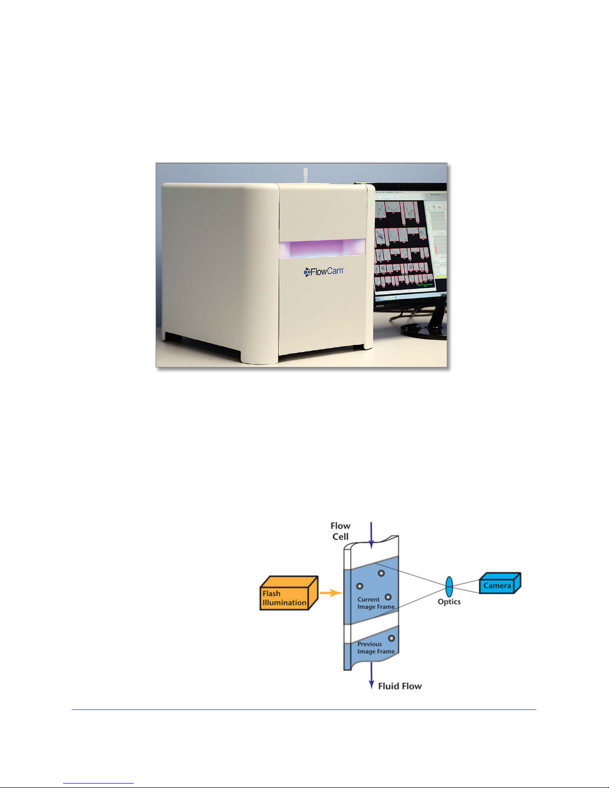
The FlowCam 8000 Series Dynamic Imaging Particle Analyzer combines selective capabilities of flow
cytometry, microscopy, and fluorescence detection to rapidly evaluate particulate matter in a moving
fluid. The FlowCam analyzer’s high-speed digital camera automatically counts, images, and characterizes
the particles or cells in a sample.
The FlowCam analyzer uses dynamic imaging particle analysis to perform these key functions:
• Examine a fluid under an objective lens backlit with a flashing LED light
• With a laser, excite particles through a laser light and detect fluorescence using two different
filters
• Capture images of the magnified particles within that fluid
• Characterize the particles using a variety of measurements
Dynamic imaging particle
analysis uses digital images to
measure the size and shape of
each particle. The sample
containing the particles streams
through the optics of the flow
cell, and the camera captures
thousands of particle images
per second.
Page 7

FlowCam® 8000 Series Dynamic Imaging Particle Analyzer
7 of 39
Optics Options
8100
8400
4X Flow Cell
• Fused quartz
FOV600, 600 µm depth x 1750 µm width
10X Flow Cell
• Fused quartz
80 µm depth x 700 µm width
20X Flow Cell
• Fused quartz
• 50 µm depth x 350 µm width
Frame Rate
Up to 100 frames per second
Image Output
8-bit grayscale TIFF and 24-bit color TIFF
Objectives
4X, 10X, 20X
Lasers
NA
Excitation wavelengths:
Red: 633 nm, 40 mW laser output
Laser Detector Bands (PMT Filters)
NA
Emission wavelengths:
Red: Ch1 700/10; Ch2 650/10
Fluorescence Detectors
NA
Two photomultiplier tubes (PMTs) in
standard configuration
Fluidics
4X Minimum/Maximum Particle Size
25 µm–300 µm
10X Minimum/Maximum Particle Size
4 µm–100 µm
20X Minimum/Maximum Particle Size
2 µm–50 µm
Minimum Sample Flow Rate
0.01 mL/min
Maximum Sample Flow Rate
20 mL/min
Technical Specifications
• FOV300, 300 µm depth x 1500 µm width
•
• FOV80
•
• FOV50
Blue: 488 nm, 40 mW laser output
Green: 532 nm, 40 mW laser output
Physical Specifications
Height: 15 in
Width: 14.125 in
Depth: 17.17 in
Blue: Ch1 650 LP; Ch2 575/30
Green: Ch1 650 LP; Ch2 525/30
Page 8
FlowCam® 8000 Series Dynamic Imaging Particle Analyzer
8 of 39
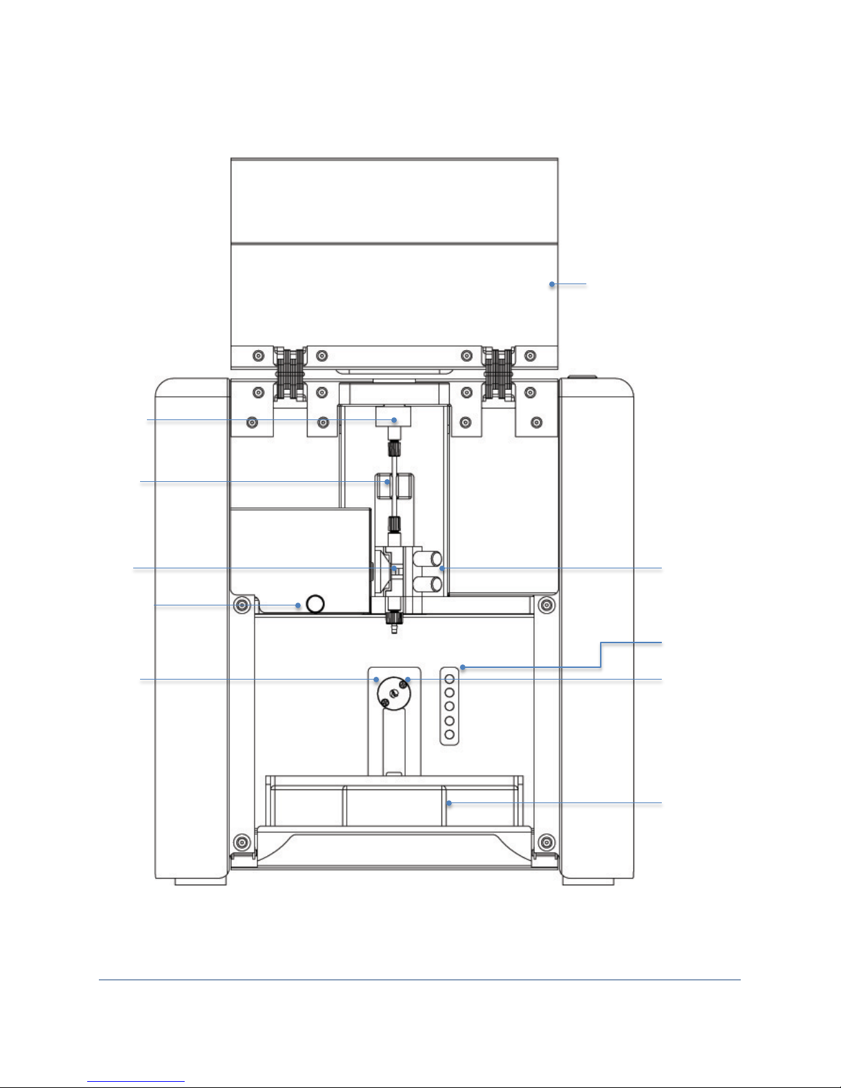
Fluid
sensor
Flow cell
Syringe
Syringe
Upper hatch
Tubing
Sample
Lower door
Flow cell
retainer
Objective
Analyzer Components
inlet port
with safety
interlock
position
and
shroud
pump
manifold
retainer
thumbscrews
manifold
valve
and bins for
fluidics
bottles
Page 9
FlowCam® 8000 Series Dynamic Imaging Particle Analyzer
9 of 39
Overview
The FlowCam 8100 and 8400 analyzers use dynamic imaging particle analysis to perform microscopic
particle measurements rapidly enough to produce statistically significant amounts of particle data. The
FlowCam analyzers gather numerous measurements for each particle, providing the detailed data
needed for a thorough particle analysis.
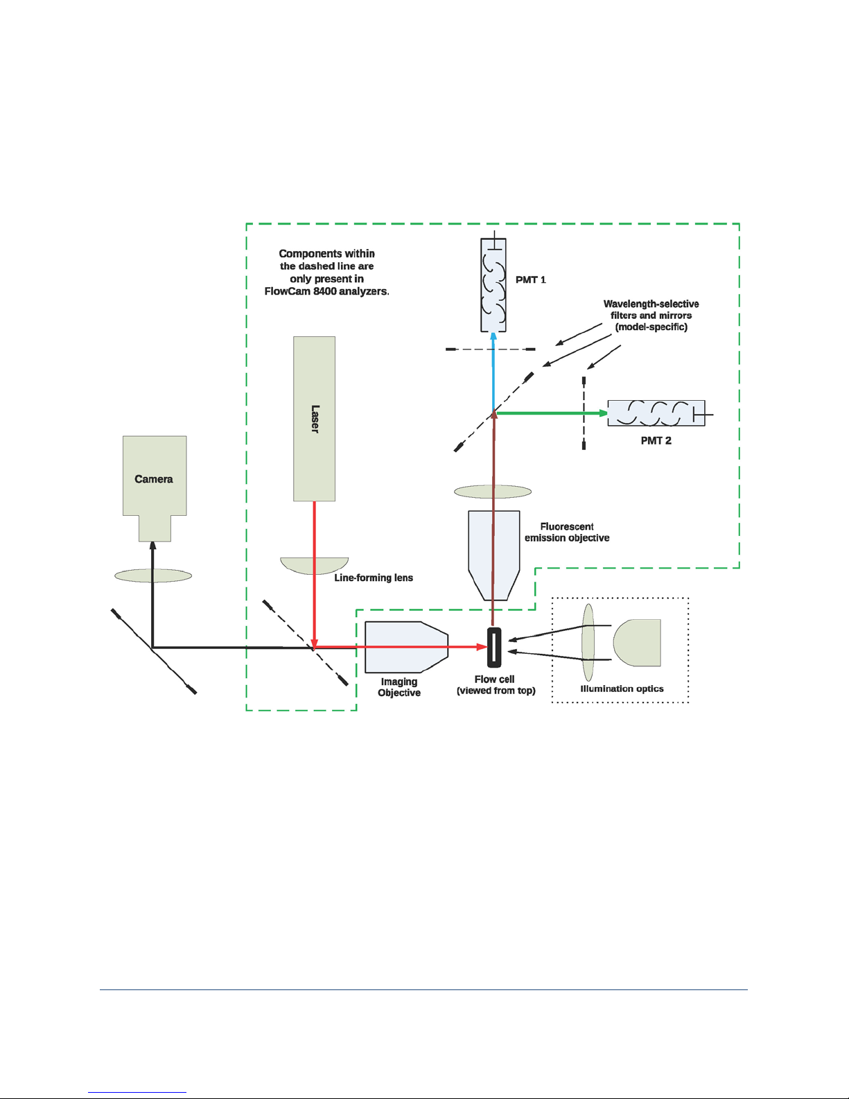
This diagram represents the general components of the FlowCam system. Your analyzer may not have all of the features shown.
• An ultra-high-precision syringe pump aspirates the fluid sample through the flow cell, which
positions the particles within the optical system.
• A high-intensity LED light source combines synchronously with a very short shutter speed in the
camera to freeze the moving particles in a fluid medium.
• The high-resolution camera, coupled with optical magnification from the objective lens,
captures thousands of particle images per second. Optional electronics capture two channels of
fluorescence data per camera frame.
• As the camera captures each frame, the VisualSpreadsheet software extracts the particle images
from the background in real time and stores them for analysis.
• The software then subjects each image to a series of more than 30 mathematical measurements
to characterize that particular particle.
Page 10
FlowCam® 8000 Series Dynamic Imaging Particle Analyzer
10 of 39
Objective
4X
10X
20X
Flow Cell
300FOV, 600FOV
80FOV
50FOV
Minimum Particle Size to
Obtain Morphological Data
Objectives
Objective lenses with varying magnification are used depending upon the application. As all optical
systems have a specific focal depth of field (DOF), it is important to select an appropriate objective/flow
cell combination to optimize image collection.
12 µm 4 µm 2 µm
Fluorescence Detection System (FlowCam 8400)
The FlowCam 8400 analyzer offers a fluorescence system to excite and detect particles that process the
property of fluorescence. The fluorescent system consists of a laser, focusing optics, and one or more
photomultiplier tubes (PMT) detectors. In front of each PMT detector is a filter that prevents the
analyzer from measuring unwanted wavelengths. The wavelength and power of the laser is applicationspecific and can be configured for a wide range of particle types.
The laser beam focuses on the center of the flow cell and when a particle with fluorescent properties
passes through the beam, the PMTs detect the fluorescent emission of light and trigger the optical
system to capture an image of the entire frame. The laser excites the particle to create a trigger event.
Relative fluorescent emission values are recorded for all particles.
In addition to minimum thresholds, the VisualSpreadsheet program offers upper thresholds that allow
you to reject overly bright or physically large particles. You can configure the program to trigger using
channel 1, channel 2 or both. You can also set the minimum and maximum threshold values of particle
intensity that you want each channel to capture.
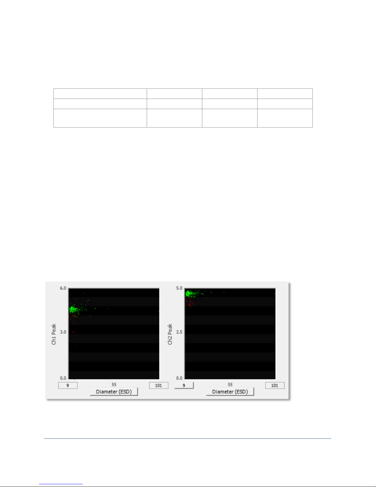
These graphs display relative fluorescence compared to diameter (ESD) for channel 1 (left) and channel
2 (right). The main population appears in green and the subpopulation in red. The graph axes autoscale
based upon the data values.
Page 11

FlowCam® 8000 Series Dynamic Imaging Particle Analyzer
11 of 39
Welcome
This guide explains how to set up, operate and maintain your FlowCam® 8000 Series Dynamic Imaging
Particle Analyzer. It also covers basic features of the VisualSpreadsheet® software application that will
assist you with the initial setup and operation of the analyzer.
Package Contents
Your shipping container includes the following items:
• FlowCam analyzer with power cord
• Monitor with power cord and connectors
• Wireless desktop (keyboard and mouse)
• Accessory case with flow cells, syringe assembly and objectives
• Autofocus beads
• Pipette tips
• Nitex mesh
• Cleaning kit
• Tubing
• Connectors (dependent upon system configuration)
• Funnel (dependent upon system configuration)
Ensure that there is no damage to the packing materials or equipment inside. If anything has been
damaged or is missing, contact Fluid Imaging Technologies or your local distribution representative
immediately. Be sure to save the white shipping container that your FlowCam analyzer came in.
Note: Use two people when lifting the analyzer. Depending upon its configuration, it could weigh in
excess of 50 pounds.
Choosing a Location
• Locate your FlowCam analyzer in a well-ventilated area that is free of vibration and dramatic
shifts in temperature.
• Place the analyzer on a clean, level, sturdy base capable of holding up to 100 pounds. Be sure to
allow space for the monitor, keyboard and mouse.
• For power, you will need two outlets, one for the analyzer and one for the monitor. We
recommend using a stable power supply with surge protection and battery backup.
Computer Peripherals
Unpack the monitor, keyboard, mouse, and their accompanying cables and power cord. These
peripheral components connect to the back of the FlowCam analyzer, which contains the
VisualSpreadsheet software program. Place the monitor, keyboard and mouse next to the FlowCam
analyzer close enough to connect them.
Page 12
FlowCam® 8000 Series Dynamic Imaging Particle Analyzer
12 of 39
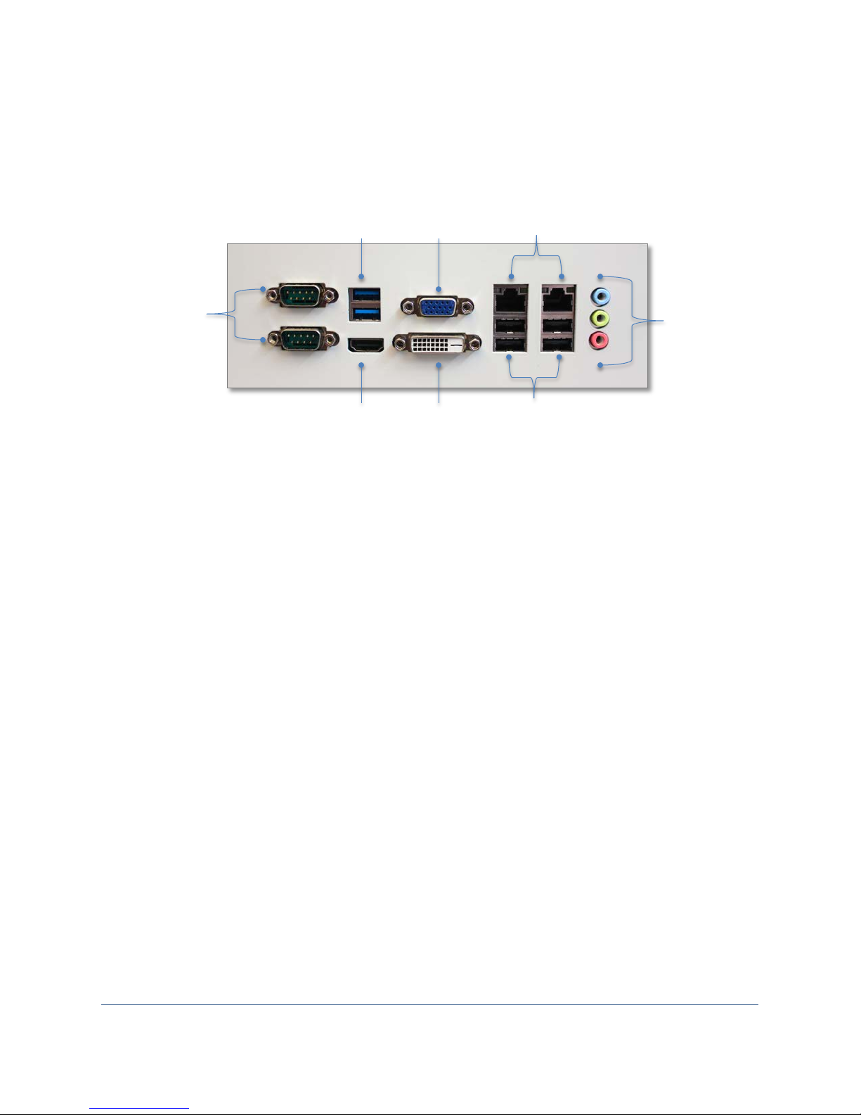
Two USB3
ports
Four USB2 ports
Two RS-232
serial ports
HDM1 port
Two Ethernet
ports
DVI port
VGA port
Audio in
Microphone in
Setting Up the Analyzer
Connecting Peripherals
Connection ports are on the back of the FlowCam analyzer.
Audio out
1. Connect the keyboard and mouse USB cables to two of the USB ports on the back on the
analyzer.
2. Connect the monitor cable to the monitor’s VGA, DVI or HDMI port (depending upon your
monitor model) and the other end to the corresponding port on the back of the analyzer.
3. Connect the monitor’s power cord to the AC input port on the monitor and plug the other end
into a power outlet.
4. Turn on the monitor’s power switch.
Powering on Your Analyzer
1. Connect the analyzer’s power cord to the AC input port on the back of the analyzer and plug the
other end into a power outlet. You will hear the analyzer’s internal fan turn on.
2. Press the round power button on the top right of the analyzer to initialize its internal pump and
the computer. The power button turns blue and you should see the startup process begin on the
monitor.
3. After a few moments, the Microsoft Windows operating system opens and the icon for the
VisualSpreadsheet software appears on the desktop.
Page 13
FlowCam® 8000 Series Dynamic Imaging Particle Analyzer
13 of 39
Preparing the Analyzer
Checking Internal Connections
Open the upper hatch and lower door on the analyzer and inspect all of the tubing connections to
ensure they are in place and secure.
• Check the inlets from the rinse and cleaner bottles into the system.
• Check the waste tubing connection from the pump to the waste container.
• Check the connection tube from the internal portion of the system to the top of the flow cell
apparatus.
Adding Solutions
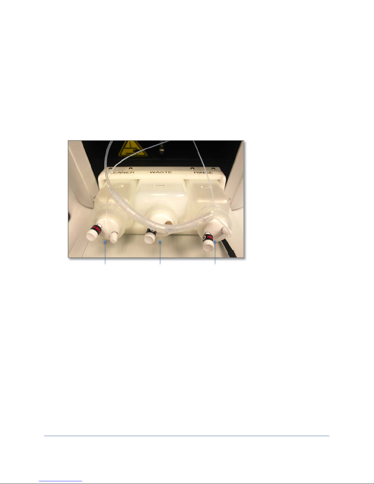
The FlowCam analyzer contains three fluid bottles—one each for cleaner, rinse and waste solutions. The
cleaner bottle should be filled with a cleaning solvent to remove remaining particles in the system. The
rinse bottle should be filled with the final solution that will flush the system before you introduce more
sample (e.g., deionized or distilled water, or buffer).
1. The three fluid bottles are located inside the lower door at the front of the analyzer.
2. Fill the cleaner and rinse bottles with the corresponding cleaning and rinse solutions you want
to use with your first sample.
3. Ensure that the caps and tubing are secure.
Page 14
FlowCam® 8000 Series Dynamic Imaging Particle Analyzer
14 of 39
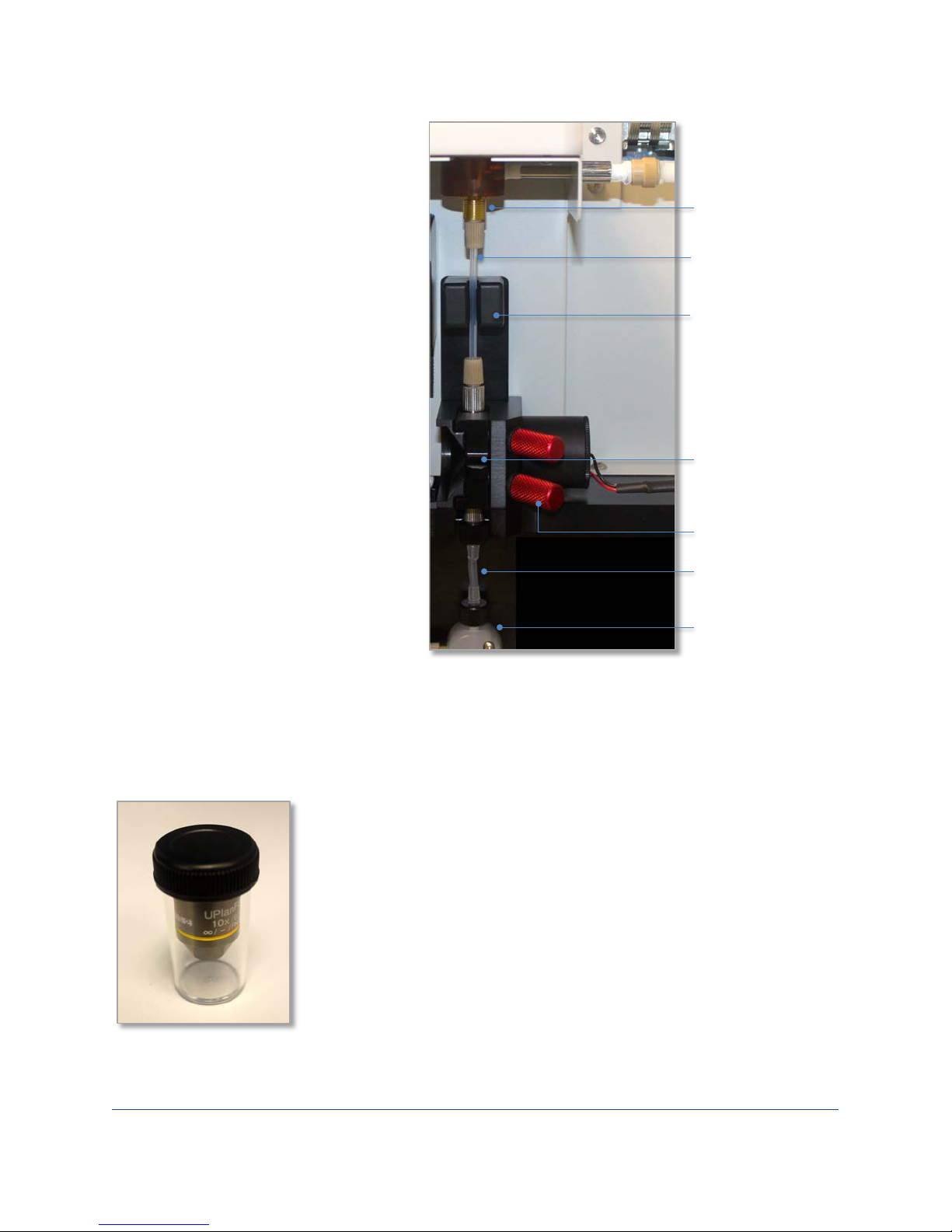
Use only labgrade water and low-lint lens paper to clean the exterior of the flow cell.
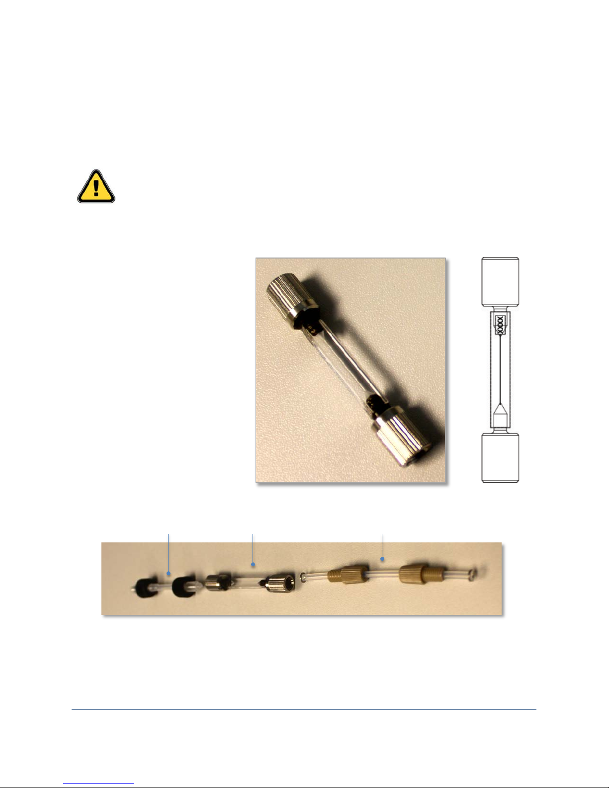
Flow cell
Upper (Teflon) tubing
Lower (silicone) tubing
Installing the Flow Cell
The flow cell is a high-precision optical component. Great care is taken during its manufacture to ensure
conformance to exacting tolerances. The polished optical faces undergo dozens of inspections to ensure
uniformity, from the certification of raw materials to the matching of the finished cells.
• The flow cell is fragile. Handle it carefully to ensure you do not damage it.
• Do not touch the faces of the flow cell with your fingers. Wear gloves when handling it.
•
• Remove the flow cell from
its protective case and
inspect it for any damage.
• Clean the outside of the
flow cell with a piece of lens
paper to remove any
particles or fingerprints.
• The front face of the flow
cell has a serial number
etched at the top of it.
• The flow cell has two pieces
of tubing that you need to
connect to it before placing
it into the analyzer.
• Connect the upper tubing to the top of the flow cell. (The etched serial number indicates the
top.) You will hear a click when the connection is secure.
• Connect the lower tubing to the bottom of the flow cell. You will hear a click when the
connection is secure.
Page 15
FlowCam® 8000 Series Dynamic Imaging Particle Analyzer
15 of 39
To install the flow cell:
10X objective lens in
Sample
Flow cell
Flow cell
thumbscrews
Syringe
manifold
Fluid
sensor
Lower
Upper
1. Open the upper hatch and lower
door of the FlowCam analyzer.
2. Loosen the flow cell retainer’s two
red thumbscrews and remove it.
3. With the flow cell’s serial number
toward you, connect the upper
tubing attached to the flow cell to
the sample inlet port.
4. Connect the lower tubing attached
to the flow cell to the syringe
pump manifold.
5. Place the flow cell into its
associated opening, and fit the
upper and lower tubing into their
respective slots.
6. Place the flow cell retainer into
the slot so that the flow cell is held
in place and tighten the two
thumbscrews.
7. Close the lower door and upper
hatch.
inlet port
tubing
position
and retainer
retainer
tubing
pump
Installing the Objective Lens
The FlowCam analyzer offers three sizes of objective lenses (4X, 10X and 20X). Depending upon your
particular system configuration, you may have multiple objective lenses.
protective container
Page 16
FlowCam® 8000 Series Dynamic Imaging Particle Analyzer
16 of 39
Objective
Objective
Objective
Note: When changing the objective lens from one magnification to another, you must also change the
pump syringe. See Appendix A for more information.
shroud
lens
stage
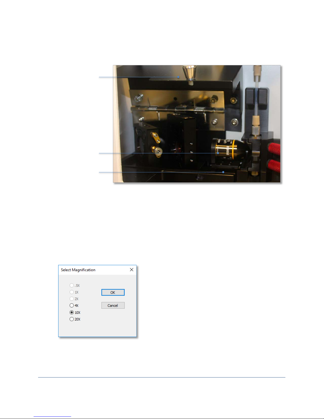
To install an objective lens:
1. Open the analyzer’s upper hatch and pull the silver knob to open the objective shroud.
2. In VisualSpreadsheet, select Setup> Change Objective. This causes the stage that holds the
objective lens to move to the left so you can access the objective fitting.
3. Carefully remove the objective lens from its container by unscrewing it from its cap.
4. Gently thread the lens clockwise into the fitting. Do not overtighten.
5. Click OK on the Change Magnification dialog.
6. The Select Magnification dialog appears. Select the applicable magnification and click OK.
7. Click OK on the Objective Lens Setup dialog. The stage moves the objective back into position
and the VisualSpreadsheet status bar displays the new objective lens value.
8. Close the objective shroud and the upper hatch.
Page 17
FlowCam® 8000 Series Dynamic Imaging Particle Analyzer
17 of 39
Autofocusing the Flow Cell
The FlowCam analyzer’s autofocus feature focuses the optical system algorithmically without operator
intervention, ensuring repeatable focus position and, therefore, measurements. To focus the flow cell,
you need the Fluid Imaging focusing standard (Autofocus Beads), other bead standards, or the sample
you will be analyzing. Use the following autofocus beads:
• Low Magnification Focus Beads for the 300FOV or 600FOV flow cell (approximately 50 μm in
diameter), 60,000 p/mL
• High Magnification Focus Beads (or 25-µm Focus Beads) for the 80FOV flow cell (approximately
25 μm in diameter)
• 10-µm Focus Beads for the 50FOV flow cell (approximately 10 μm in diameter)
To autofocus the flow cell:
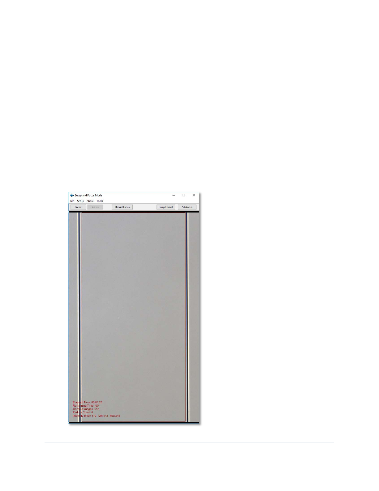
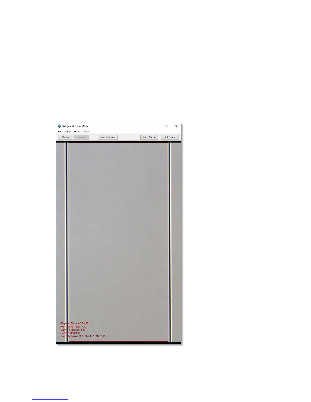
1. From the tool bar, click the Setup and Focus tool to open a live view of the camera window on
the flow cell.
The acceptable region
lies within the red
indicator lines. The
acceptable region is set
in the Context settings.
Note: When fluid is primed into the flow cell, the intensity mean should be ~150–180.
Page 18
FlowCam® 8000 Series Dynamic Imaging Particle Analyzer
18 of 39
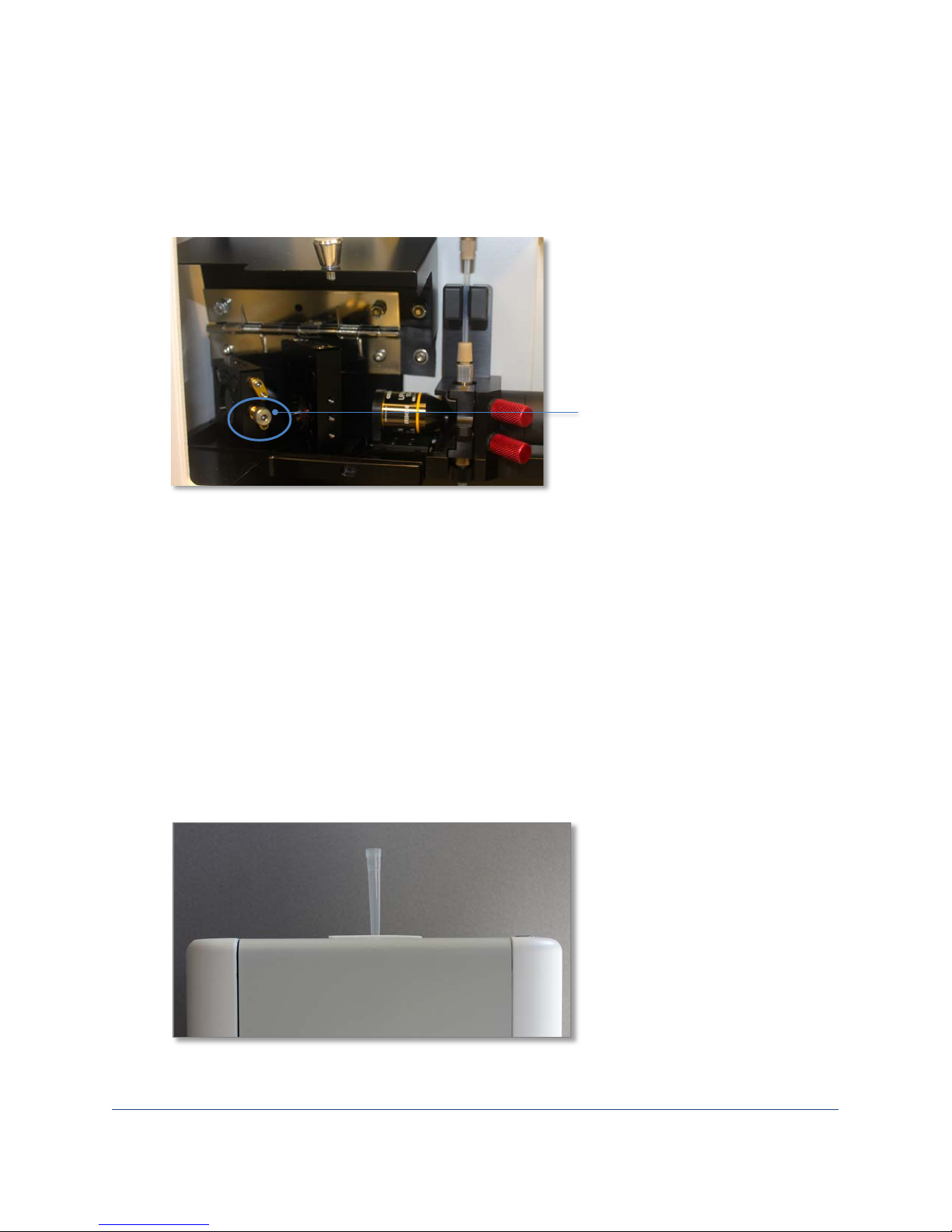
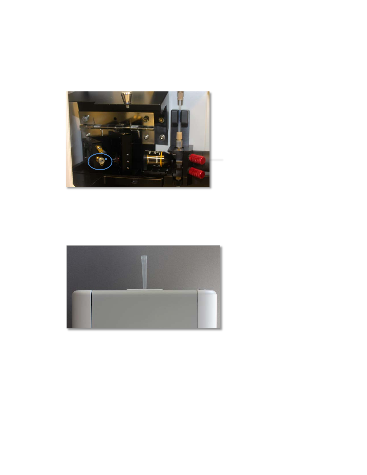
Flow cell positioning knob
2. If necessary, align the flow cell to the correct position using the positioning knob located to the
left of the flow cell assembly in the interior of the analyzer. The flow cell can be moved left and
right.
Note: The red lines need to be positioned within the gray lines, which represent the walls of the
flow cell. Align the red indicator lines as close as possible within the flow cell.
3. Click the Autofocus button. The Autofocus Assistant opens. Click Next and and follow the
onscreen prompts.
4. Confirm that you have the correct objective lens, flow cell and syringe installed, and click Next.
5. Select the desired autofocus algorithm option (Best Bead Count or Best Focus Image) and click
Next.
Note: Select the algorithm depending upon whether you are running uniform materials for
primarily counting, or varied particles for image quality. The stage assembly orients itself
depending upon the selection after the routine is completed.
6. Place a pipette tip into the sample introduction port on the top of the analyzer and add at least
0.5 mL of focusing sample. Click Next. The pump draws the sample into the flow cell and the
analyzer begins the autofocus process.
Important: Apply some pressure to ensure the tip is securely in the port to prevent air from
being drawn into the system.
7. When the autofocus process finishes, a message appears indicating success. Click Start Flush to
flush the solution from the system. The pump continues until you click Stop.
Page 19
FlowCam® 8000 Series Dynamic Imaging Particle Analyzer
19 of 39
8. Close the Setup and Focus Mode window. You are now ready to begin analyzing samples.
Note: You only need to perform the autofocus routine upon initial startup, and after you change
the flow cell or the objective lens. Otherwise, you can use the manual focus process to adjust
the focus of individual samples. The autofocus log files are saved to Documents>
Visualspreadsheet> Autofocus Logs.
Focusing the Flow Cell Manually
To focus the flow cell:
1. From the tool bar, click the Setup and Focus tool to open a live view of the camera window on
the flow cell.
The acceptable region
lies within the red
indicator lines. The
acceptable region is set
in the Context settings.
Note: When fluid is primed into the flow cell, the intensity mean should be ~150–180.
Page 20
FlowCam® 8000 Series Dynamic Imaging Particle Analyzer
20 of 39
Flow cell positioning knob
2. If necessary, align the flow cell to the correct position using the positioning knob located to the
left of the flow cell assembly in the interior of the analyzer. The flow cell can be moved left and
right.
Note: The red lines need to be positioned within the gray lines, which represent the walls of the
flow cell. Align the red indicator lines as close as possible within the flow cell.
3. Click the Manual Focus button. A warning appears. Click OK.
4. Using a pipettor with an ejector, pipette at least 0.5 mL of focusing sample, place the pipette tip
into the sample introduction port on the top of the analyzer, eject it and leave it there.
Important: Apply some pressure to ensure the tip is securely in the port to prevent air from
being drawn into the system.
5. In the VisualSpreadsheet Setup and Focus window, click the Pump Control button to open the
Pump Control dialog.
Page 21
FlowCam® 8000 Series Dynamic Imaging Particle Analyzer
21 of 39
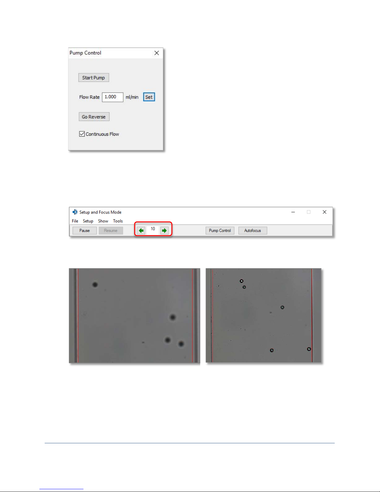
6. Enter a flow rate (for example, 1), click Set, and then click the Start Pump button to draw the
sample down into the flow cell.
7. As the sample flows, focus the view by clicking the left and right green arrows on the Setup and
Focus Mode window until the edges of the particles become clear. The default value is 10, but
you can increase or decrease the value to change the amount of objective movement.
Tip: You can click the Pause Pump button to suspend the flow and achieve optimum focus. Then
click Resume Pump. You can also pinch the tubing below the flow cell to suspend desired beads.
Unfocused beads Focused beads
Note: Focused beads have a high edge-gradient value and sharp bead perimeters.
8. Close the Pump Control dialog and the Setup and Focus Mode window. You are now ready to
begin analyzing samples.
Page 22
FlowCam® 8000 Series Dynamic Imaging Particle Analyzer
22 of 39
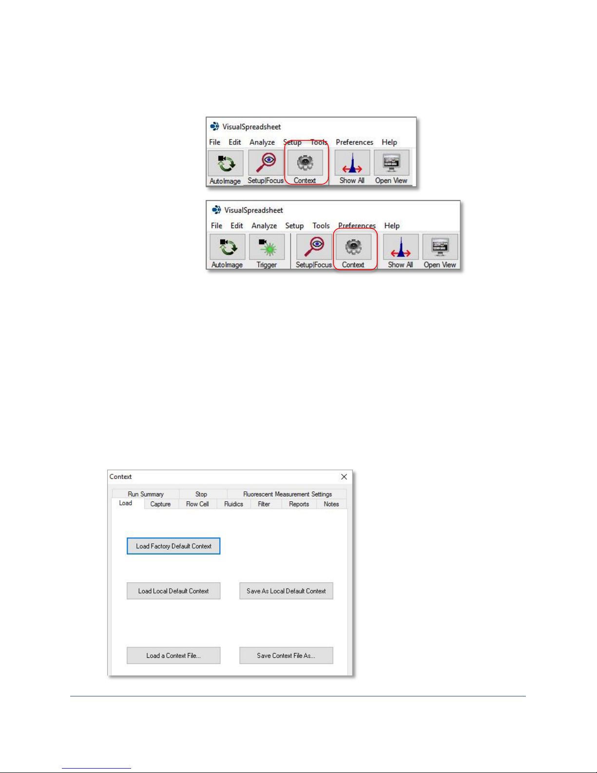
FlowCam 8100
FlowCam 8400
Defining the Context Settings
1. On the toolbar, click the Context tool.
toolbar
toolbar
2. The Context dialog opens.
The Context dialog contains the settings used by the FlowCam analyzer to capture particles of
interest during a sample analysis. This includes settings for the camera, fluorescent thresholds
and gains, and other various parameters. The settings can be saved in a context file
(filename.ctx) within a folder that contains all the files for a particular analysis. Basic software
settings from the factory and your local default settings are also saved in context files.
3. Click the individual tabs (Load, Capture, Flow Cell, Fluidics, Filter, Stop) to enter the desired
applicable settings.
Note: See the VisualSpreadsheet documentation for additional information.
4. The Load tab lets you save your settings to a context file, or load a specific context file that you
have previously saved.
Note: The default settings can be reset by clicking the Load Factory Default Context button.
Page 23
FlowCam® 8000 Series Dynamic Imaging Particle Analyzer
23 of 39
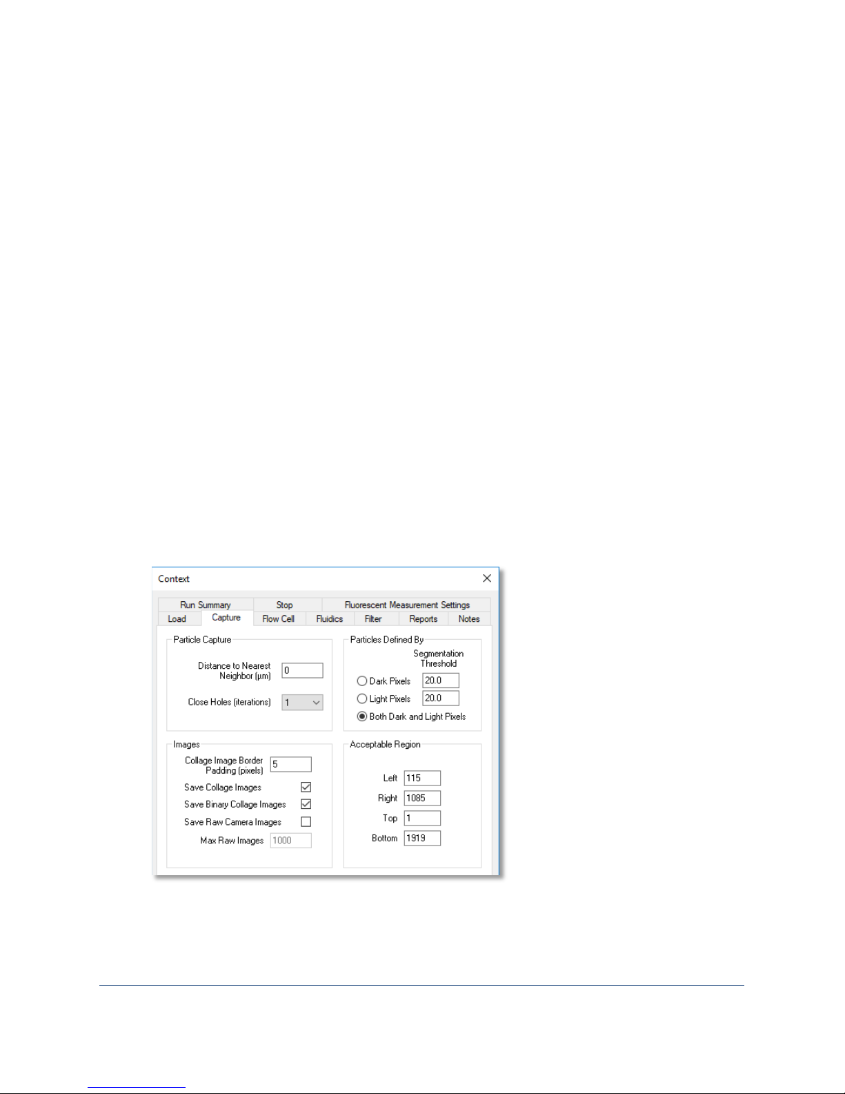
5. The Capture tab lets you set specific parameters for capturing particles, such as:
• Distance to Nearest Neighbor—Any particles that are equal to or less than this distance in
microns from each other will be imaged as one particle.
• Close Holes (iterations)—Closing holes is a standard morphological operation used to fill in
small gaps in an image that may have been lost due to a threshold setting being too high or
the particle image being too faint.
• Collage Image Border Padding (pixels)—Keeps an additional border of pixels around a
particle when cropping from the raw camera image.
• Save Collage Images—Saves all images (segmented particles from a raw camera image)
captured during a run.
• Save Binary Collage Images—Saves a visual overlay of the pixels determined to be a particle.
• Save Raw Camera Images—Saves each raw camera image (that is, the image of the camera
field of view).
• Max Raw Images—Defines the maximum number of raw images to be saved when the Save
Raw Camera Images option is selected.
• Particles Defined by Pixels—These parameters provide threshold values for the software
during routine acquisition. The density of the particle is defined relative to the background
and the illumination.
• Acceptable Region—These values define the region in an image where particles are
captured. Choose Setup> Focus to define the acceptable region.
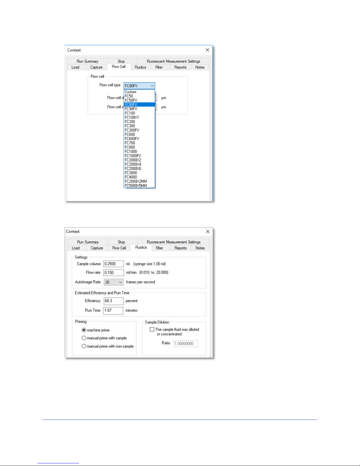
6. The Flow Cell tab lets you select the type of flow cell being used, which automatically enters its
depth and width.
Page 24
FlowCam® 8000 Series Dynamic Imaging Particle Analyzer
24 of 39
7. The Fluidics tab is where you define the sample volume, flow rate, autoimage rate, efficiency,
run time, priming type, and sample dilution parameters.
Note: The machine prime option uses the built-in functionality of the fluid position sensor.
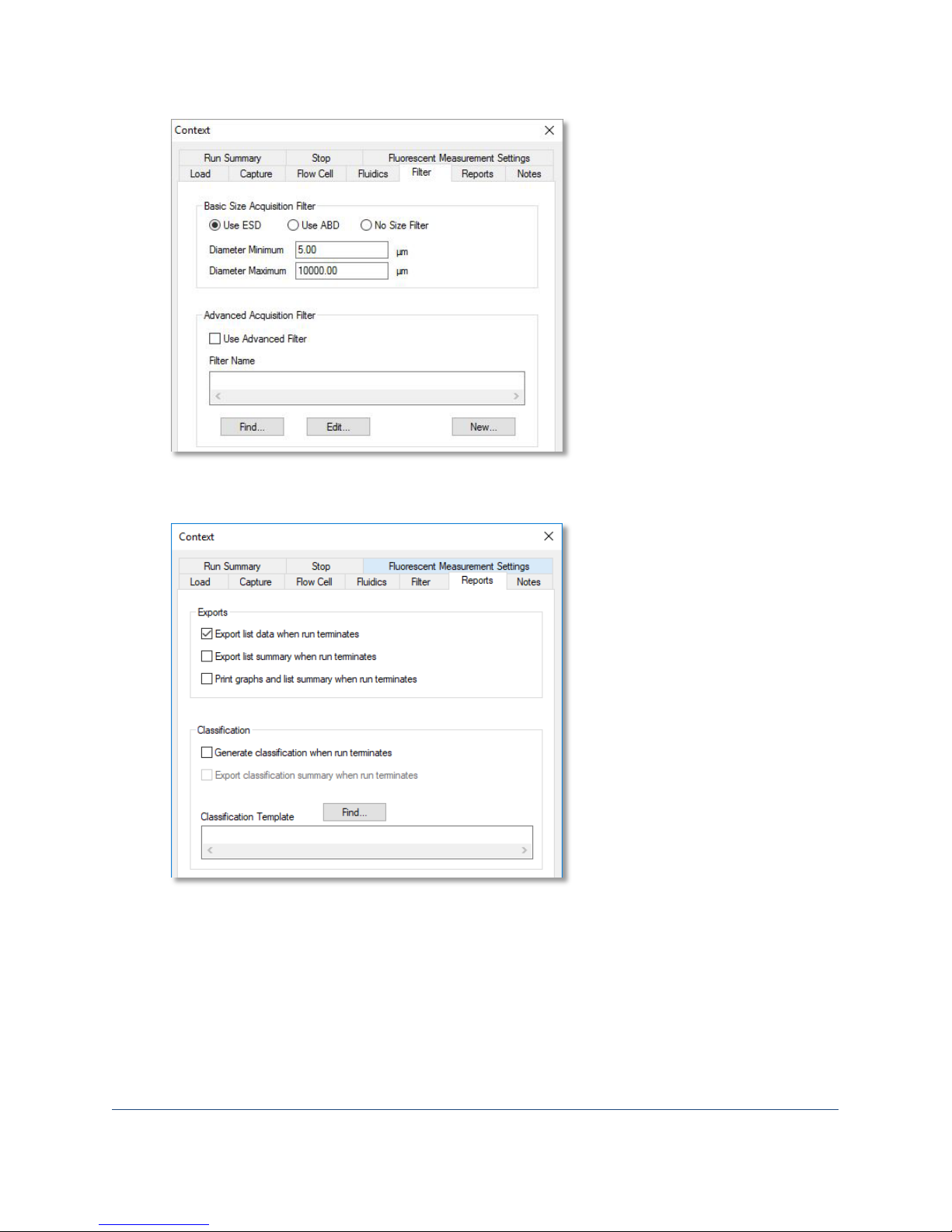
8. The Filter tab lets you select an image filter (ESD, ABD, none, advanced) and set its minimum
and maximum diameter values to specify the size range of the particles of interest to save.
Page 25
FlowCam® 8000 Series Dynamic Imaging Particle Analyzer
25 of 39
9. The Reports tab provides options for exporting and printing reports when an analysis finishes, as
well as options for performing classification.
10. The Notes tab provides a space to enter comments about the sample analysis. These notes are
saved as a text file in the sample run data folder. The filename begins with the List filename
appended with _notes.txt.
11. When an analysis finishes, the Run Summary tab displays summary information about the
sample analysis. This data is saved as a text file in the sample run data folder. The filename
begins with the List filename appended with _run_summary.txt.
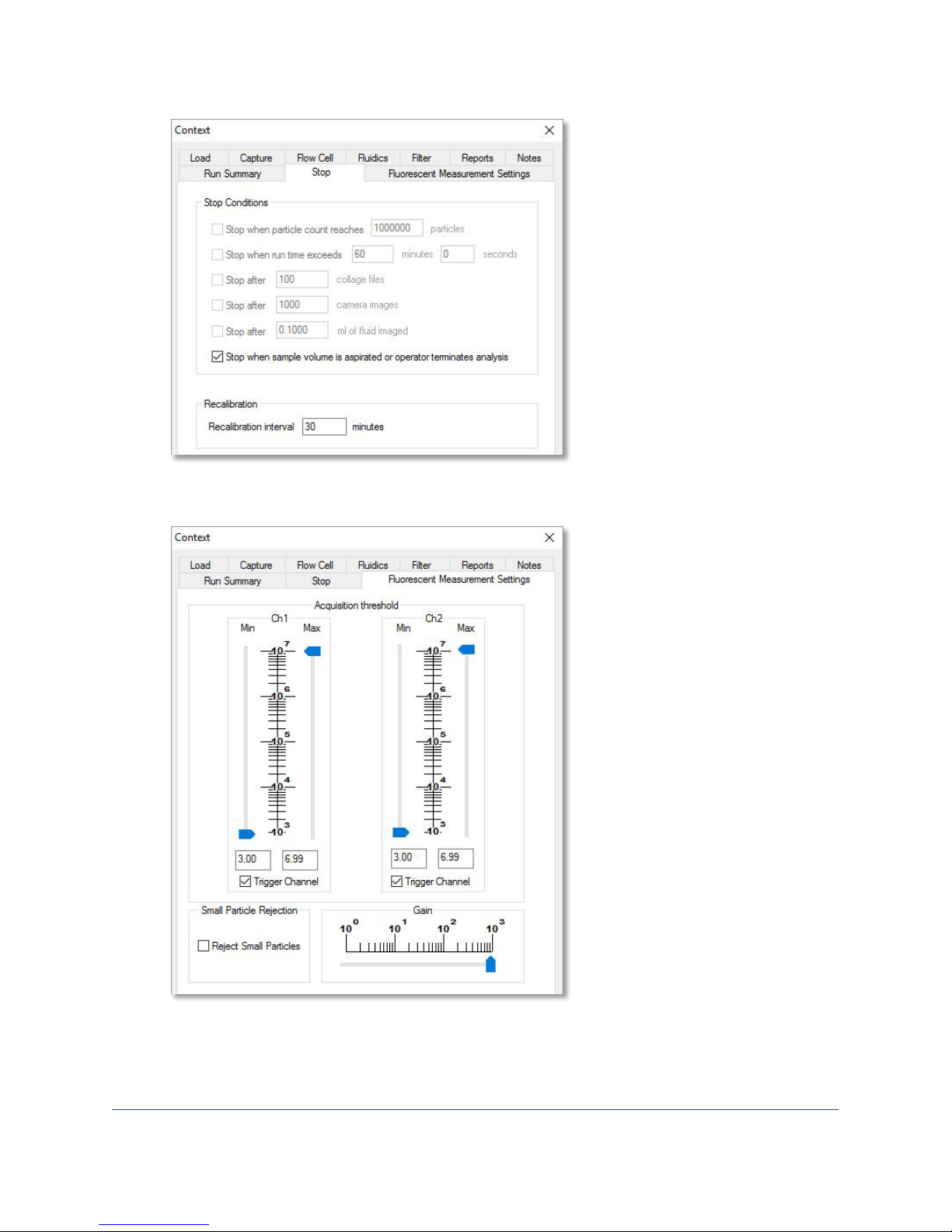
12. The Stop tab offers options for terminating an analysis under certain conditions. You can select
multiple options and the analysis stops when the first condition is met.
Note: The operator can manually override any stop setting by closing VisualSpreadsheet.
Page 26
FlowCam® 8000 Series Dynamic Imaging Particle Analyzer
26 of 39
13. (FlowCam 8400 analyzer only) The Fluorescent Measurement Settings tab is where you set
thresholds for particle acquisition and rejection.
14. Click OK to save your context settings.
Page 27
FlowCam® 8000 Series Dynamic Imaging Particle Analyzer
27 of 39
Performing a Sample Analysis
Before sample analysis, perform the following steps:
• Check the fluidics bottles. Fill the cleaner and rinse bottles, if necessary, and empty the waste
bottle.
• If necessary for the particular sample, change the flow cell.
• If necessary for the particular sample, change the objective lens and pump syringe.
• Define the context settings for the sample.
To run a sample:
1. Using a pipettor with an ejector, pipette at least 1 mL of sample, place the pipette tip into the
sample introduction port on the top of the analyzer, eject it and leave it there.
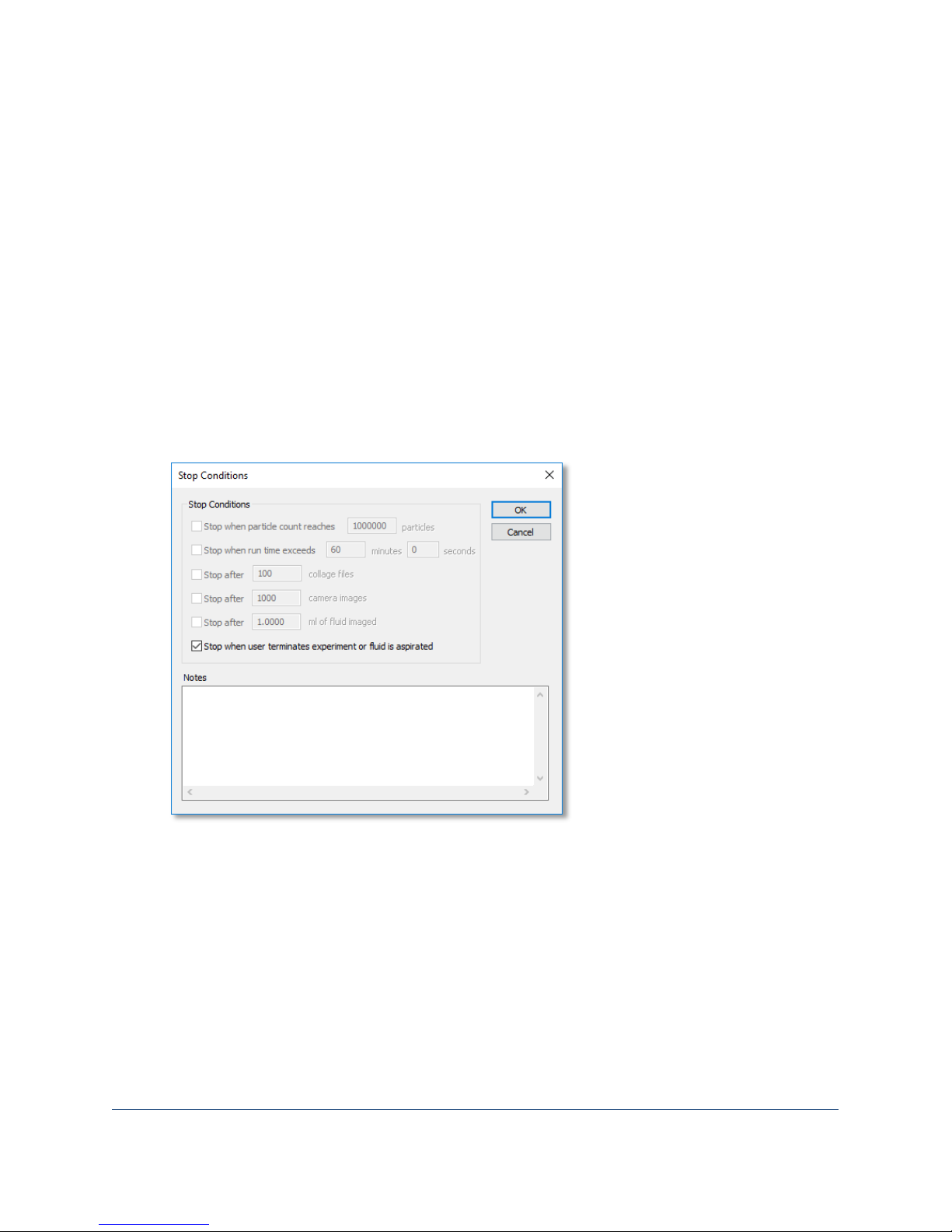
2. Click the AutoImage (or Trigger Mode) tool on the toolbar. The Stop Conditions dialog opens.
3. Select any desired stop conditions, enter any desired notes and click OK.
4. Click Save to enter a filename and save your list file.
Note: The default filenaming scheme is the Julian day and time on the FlowCam computer.
5. The analyzer begins pulling the sample, the AutoImage window indicates that the analyzer is
calibrating, and the Collage window opens so you can see the images being captured.
6. When the sample finishes, the Collage window closes.
7. Click the Show All button on the toolbar to see the results.
8. Click the Open View button to see the images.
Page 28
FlowCam® 8000 Series Dynamic Imaging Particle Analyzer
28 of 39
Cleaning and Rinsing the Analyzer
After analysis, clean and rinse the system to remove any leftover particles—using the pump’s flush
feature or performing a manual cleaning and rinsing.
Flush the System
1. Select Setup> Pump from the menu bar. The Pump Controller dialog opens.
2. Select the number of flushes (example 5 flushes for a 1-mL syringe equals a 5-mL flush).
3. Click the Flush button. When the system flush finishes, a message appears onscreen.
4. Close the message and close the Pump Controller dialog.
Manual Clean and Rinse
1. Add some cleanser in a new tip in the analyzer’s sample inlet port.
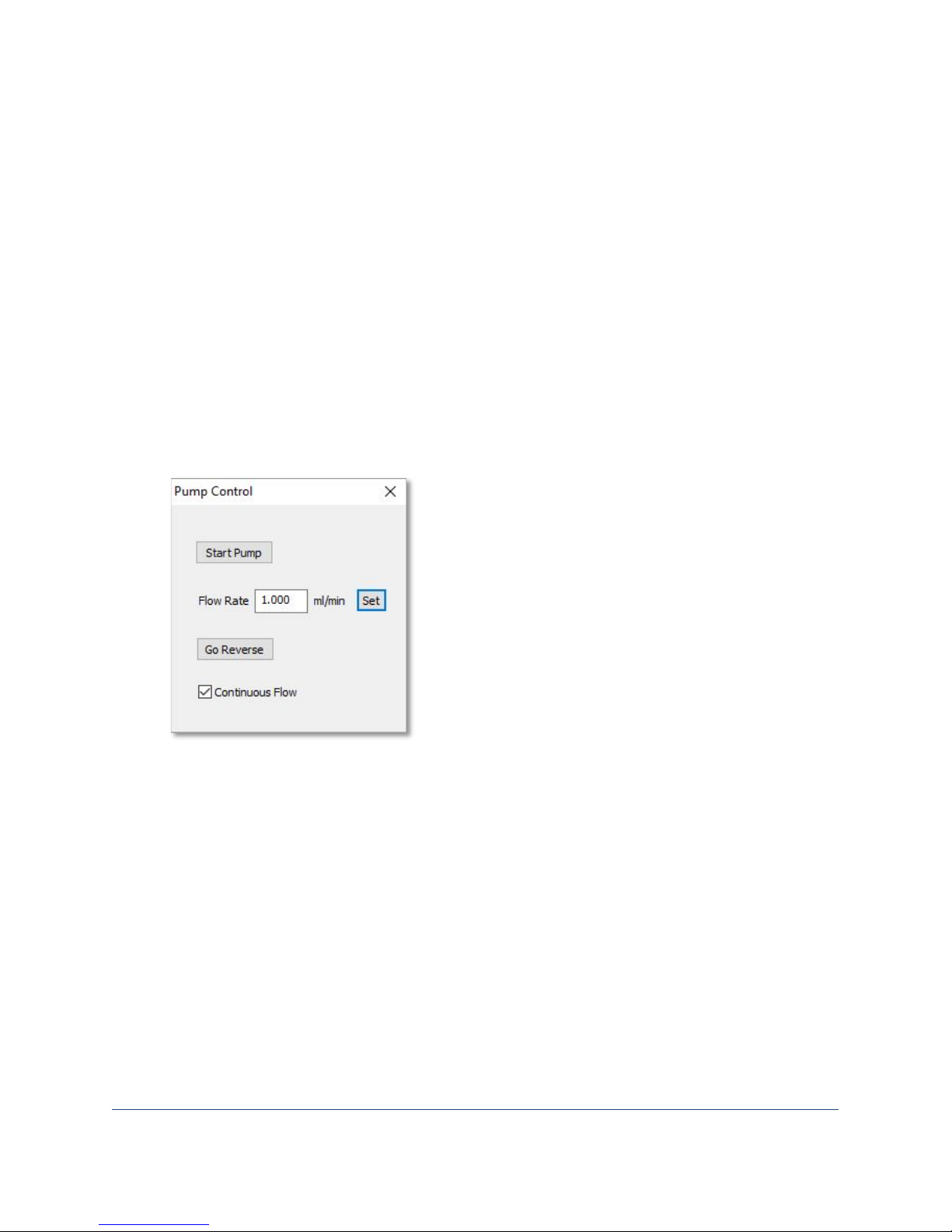
2. Click the Setup and Focus tool and then click the Pump Control button to open the Pump
Control dialog.
3. Click the Start Pump button.
4. When all of the cleanser has been drawn into the system, click Pause Pump.
5. Add some rinse solution to the tip in the sample inlet port and click the Start Pump button.
6. After all of the cleanser has been drawn into the system, click Stop Pump.
Automatic Clean and Rinse Cycles
You can set up automatic clean and rinse cycles to occur at the end of your sample analysis.
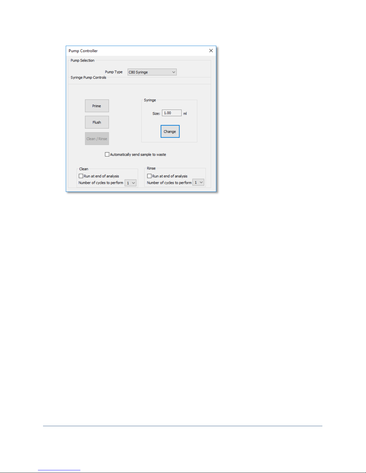
1. Select Setup> Pump from the menu bar. The Pump Controller dialog opens.
Page 29
FlowCam® 8000 Series Dynamic Imaging Particle Analyzer
29 of 39
2. Select the Run at end of analysis checkbox for the Clean option.
3. Click the Number of cycles to perform drop-down list and select the desired number of clean
cycles.
Note: You cannot run the clean function without also running the rinse function.
4. Select the Run at end of analysis checkbox for the Rinse option.
5. Click the Number of cycles to perform drop-down list and select the desired number of rinse
cycles.
6. Close the Pump Controller dialog to save your settings.
Powering Down the Analyzer
1. Close the VisualSpreadsheet program.
2. Push the power switch on the top right of the analyzer cover. The computer shuts down and the
monitor turns off automatically.
Note: The FlowCam analyzer’s fluidics components continue to operate, along with the system’s
internal fans. Turning off the main power supply unit shuts down the entire system.
3. Turn off the main power supply unit that the system components are plugged into.
Page 30

FlowCam® 8000 Series Dynamic Imaging Particle Analyzer
30 of 39
Care and Maintenance
General
Immediately after use, rinse the analyzer system with appropriate cleaner. This rinse will help keep
the flow cells clear and free from contamination for day-to-day use. If necessary, precede the rinse
with a solvent or surfactant to remove particles.
Flow Cell
• Immediately after use, or if you suspect that the flow cell is obstructed, remove the flow cell
from the upper and lower tubing connections, and clean it as follows:
o Use a warm water jet first, followed by dilute detergent, and then a warm water jet to rinse.
o Do not use an ultrasonic cleaner.
o Do not blow dry flow cells with compressed air.
o Never use tap water with flow cells.
o Use a final rinse of deionized water.
• Never leave a flow cell with sample or material inside when not using the analyzer.
• Inspect the flow cell channel frequently for contamination or obstructions. The inspection
should include removing the tubing from each end to look into the channel.
• Carefully inspect your flow cell using a compound microscope at 40X total magnification,
especially the ends of the flow cell chamber.
• Clean your flow cell with a dilute solution of lab cleanser. We recommend that you use luer-lock
fittings attached to a syringe to obtain a tight seal with your flow cell.
• Cleaner can be stored inside your flow cell overnight.
• After cleaning, use ample washes of deionized water to remove any cleaner.
• Before installation, clean the exterior of the flow cell with
paper.
Fluidics Bottles and Tubing
• Inspect the tubing connections frequently to ensure they are in place and secure, and have no
leaks or cracks.
• Check the caps on the bottles to ensure they are sealed tightly.
• Empty the waste bottle daily.
Analyzer
• Always disconnect the power cord from its power source before cleaning the analyzer.
labgrade water and a low-lint lens
• Clean the outside of the analyzer with a damp (not wet) lint-free cloth. A mild disinfectant or
liquid soap will remove grease.
• Never blow canned or compressed air into the analyzer.
Page 31
FlowCam® 8000 Series Dynamic Imaging Particle Analyzer
31 of 39
Appendix A: Changing the Pump Syringe
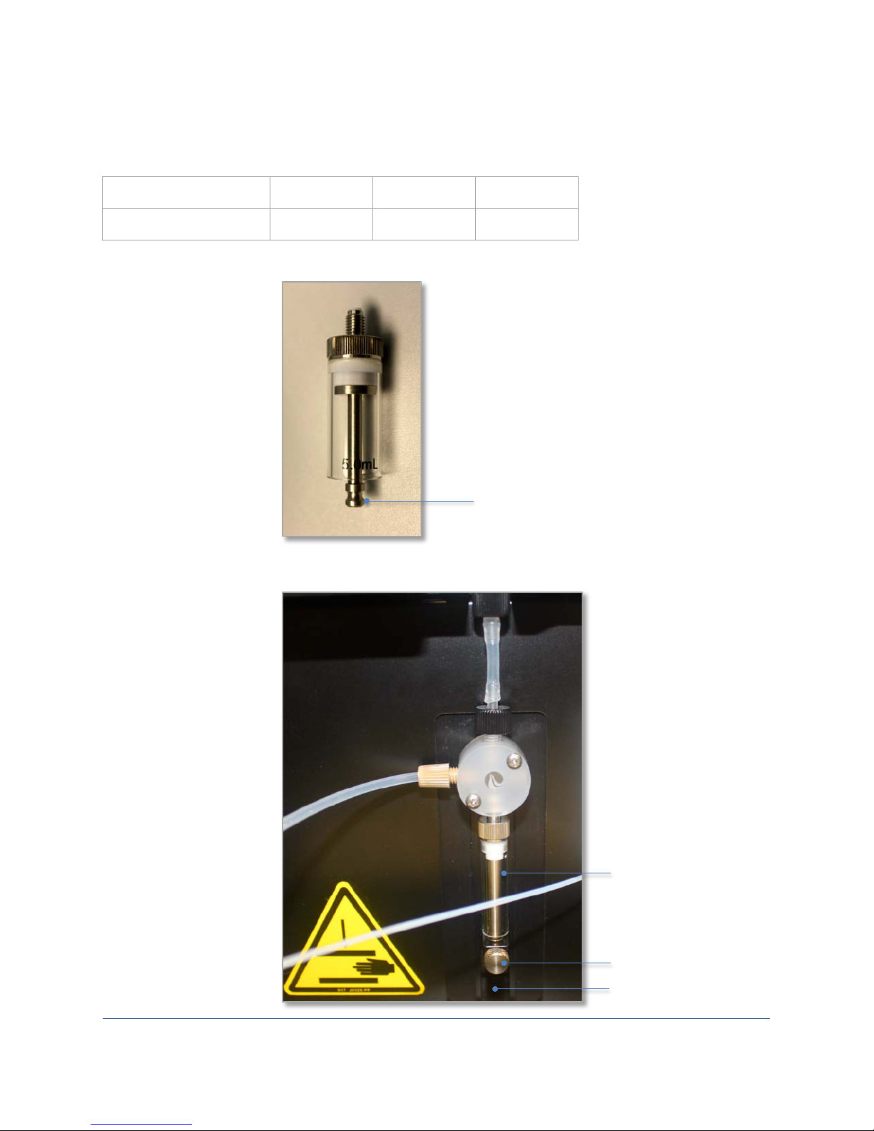
The FlowCam analyzer has three pump syringes that accommodate the three objective lenses.
Objective Lens Power 4X 10X 20X
Pump Syringe Size 5 mL 1 mL 0.5 mL
5-mL pump syringe
Plunger
Syringe pump
Syringe
Plunger lock screw
Plunger base
Page 32
FlowCam® 8000 Series Dynamic Imaging Particle Analyzer
32 of 39
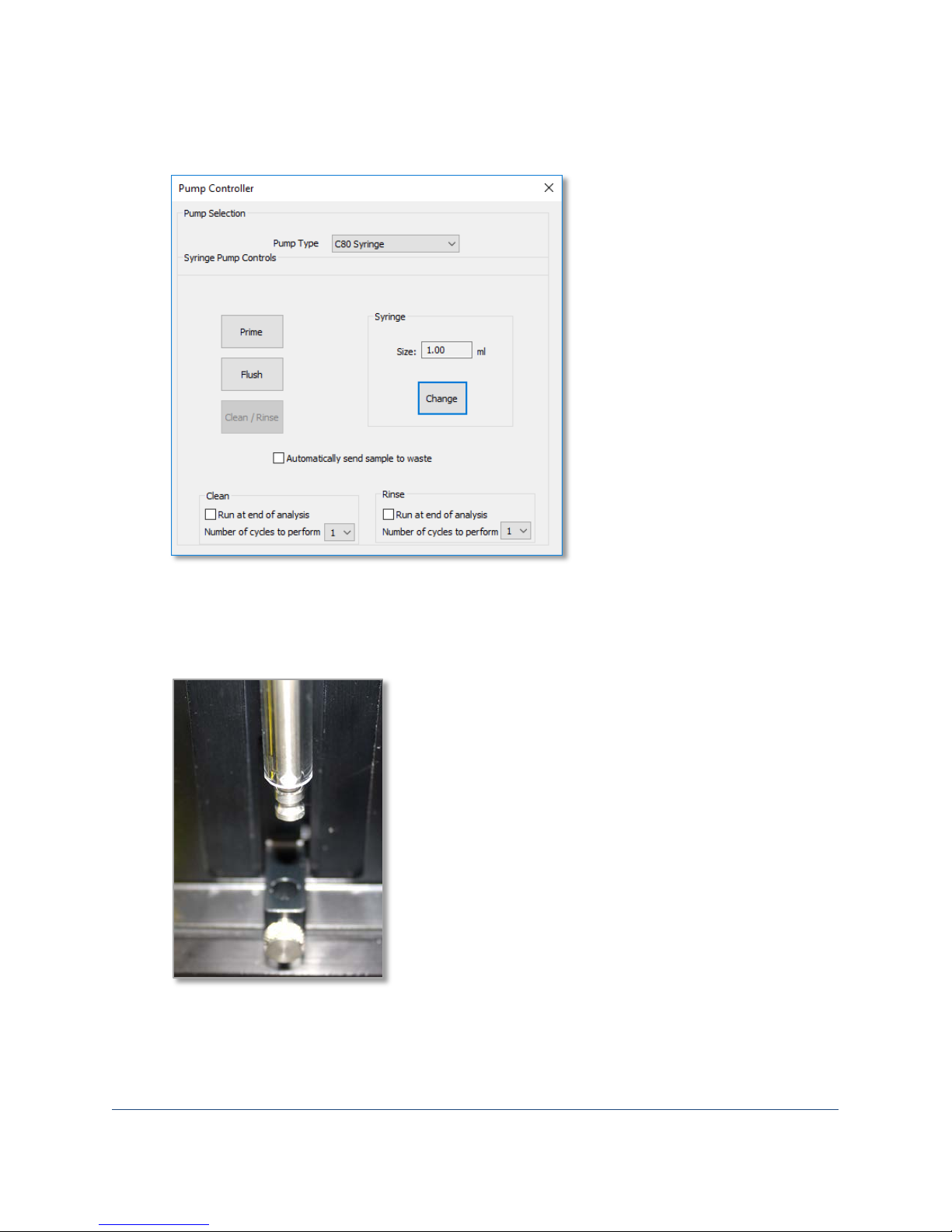
To change the pump syringe:
1. Select Setup> Pump from the menu bar. The Pump Controller dialog opens.
2. Click the Change button under the Syringe options.
3. A message asks if you want to change the syringe. Click Yes, and follow the onscreen prompts.
4. Turn the plunger lock screw counterclockwise three turns. Click OK. The plunger base moves
down to allow for removal.
5. Unscrew the syringe from the valve, and remove it.
6. Screw the new syringe into the valve, and center the plunger in the syringe. Click OK. The
plunger base moves back into place.
7. Securely tighten the plunger lock screw. Click OK.
Page 33
FlowCam® 8000 Series Dynamic Imaging Particle Analyzer
33 of 39
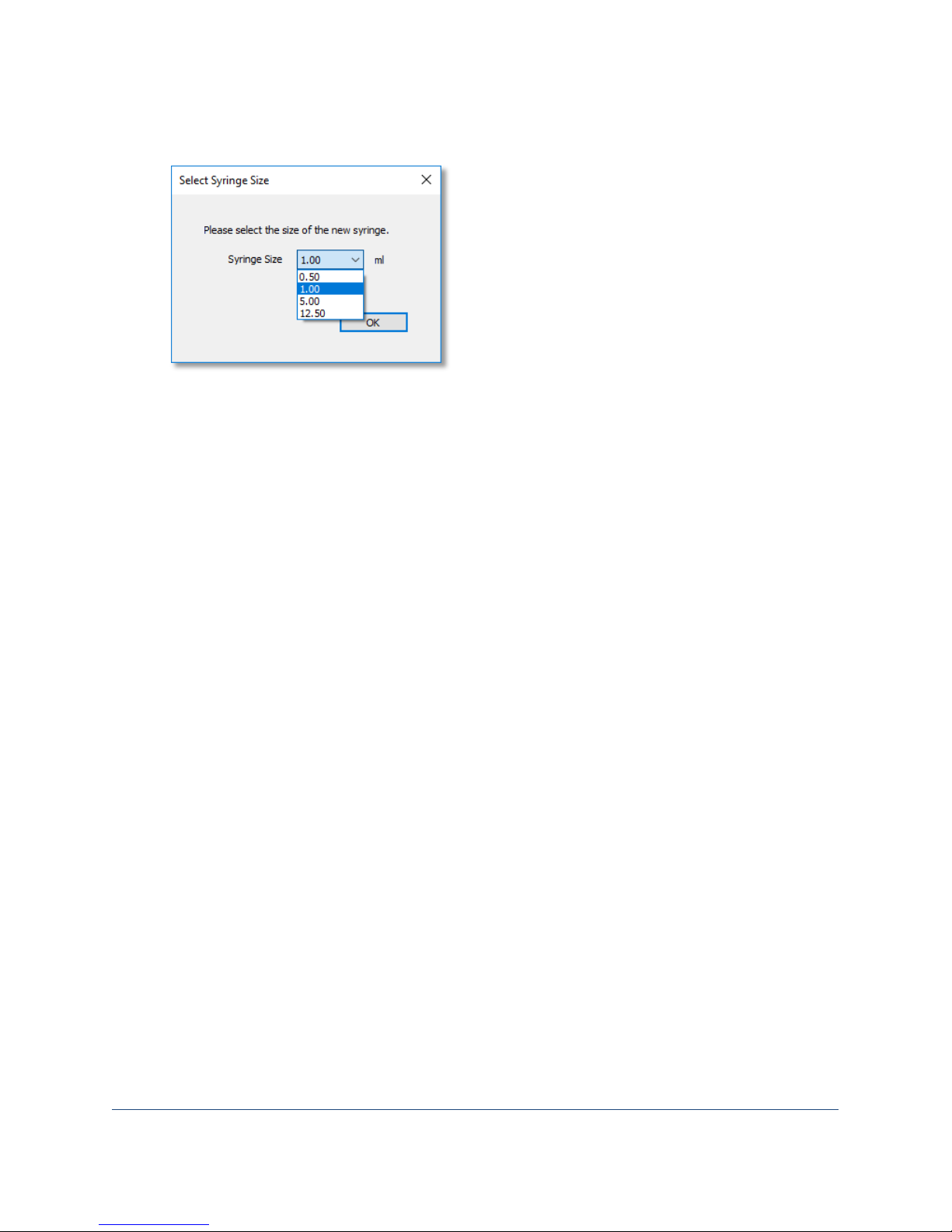
8. The Select Syringe Size dialog appears. Select the applicable size from the Syringe Size drop-
down list and click OK.
9. Clean the previous syringe and replace it in its container.
Tip: Remove the plunger from the syringe casing to thoroughly clean the syringe.
Page 34

FlowCam® 8000 Series Dynamic Imaging Particle Analyzer
34 of 39
Appendix B: Frequently Asked Questions
Q. How do I clean a clogged flow cell?
A. Flow cell handling and cleaning instructions were shipped with your instrument. If you did not receive
these instructions, contact a member of our customer support team to order your flow cell cleaning and
maintenance kit. If you have a kit, see the instructions included and ensure that the flow cell is clean by
verifying with a stage microscope. You should observe the cone regions at either end, as well as the
internal flow cell chamber.
Online video instructions are available at: https://youtu.be/Vz-0FjRcUpw
Q. Do I need to refocus my flow cell after I change the objective?
A. If you performed the autofocus process with the previous objective, the software retains the original
position of that focus routine. However, you can override the autofocus routine by using the manual
focus feature.
Q: How often do I need to calibrate my analyzer?
A: The analyzer arrives with a factory-set calibration. You can locate the calibration factor reported in
your shipping files on the analyzer configuration sheet. If you are required to conduct regular instrument
checks, performing a standard calibration check with Count-Cal bead standards satisfies routine
calibration checks. See the consumables information at
http://www.fluidimaging.com/support/ordersupplies for further information on bead sizes. All factory settings are performed using NIST traceable
standards.
Q: How do I reset my fluid bottles?
A: When the bottles of cleaner or rinse solutions are empty, remove the threaded cap and refill the
contents. From the VisualSpreadsheet menu bar, select Tools> Reset Fluid Levels. A dialog confirms the
fluid levels in the bottles.
Page 35

FlowCam® 8000 Series Dynamic Imaging Particle Analyzer
35 of 39
Appendix C: Services
Training
Let our knowledgeable staff teach you how to operate and effectively use your FlowCam analyzer and
VisualSpreadsheet software. Hands-on training with a technical customer support technician provides
the most thorough training experience because it is designed specifically for your application. Fluid
Imaging Technologies offers four types of training/learning opportunities.
• Initial training usually occurs on-site at your group’s facility soon after your FlowCam analyzer
arrives. This training is hands-on and suitable for a small group of 4–5 individuals.
• FlowCam workshops are one- or two-day trainings or demonstrations held at Fluid Imaging
Technologies headquarters in Scarborough, Maine. Our laboratory houses our legacy and our
new 8000 series FlowCam analyzers. We can walk your group through our latest software and
instrumentation using your own sample that you provide. Also, it’s an opportunity to visit
beautiful Maine!
• On-site refresher training is appropriate for on-boarding a new group of FlowCam analyzer
users, reviewing training topics for a new field season, or training existing employees who need
a refresher.
• Remote learning sessions (RLS) are ideal for refresher training, for on-boarding new employees,
or for our international customers whose travel expenses might be cost-prohibitive. RLS training
occurs on your FlowCam analyzer and VisualSpreadsheet program on a computer via Citrix Go to
Assist as our secure method of screen sharing. The session can be recorded upon request.
Preventive Maintenance Service
A preventive maintenance service is designed to help ensure that your FlowCam analyzer is always
operating at its optimum. Preventive maintenance service includes:
• Certification that your FlowCam analyzer is calibrated using NIST-traceable standards
• Thorough evaluation and cleaning of all accessory parts
• Testing of all hardware and software
• Replacement of common wear items, such as tubing and fittings (consumable items, such as
flow cells, are not replaced)
• VisualSpreadsheet software upgrade for the FlowCam analyzer and one satellite license
A preventive maintenance service conducted at your site includes a half-day refresher training session
with a Fluid Imaging Technologies technician.
Page 36

FlowCam® 8000 Series Dynamic Imaging Particle Analyzer
36 of 39
Installation and Operational Qualification
An installation and operational qualification (IOQ) service is performed when the instrument must be
qualified for use. IOQs occur either during initial receipt of a FlowCam analyzer or after it is relocated
within a company property.
• IOQ service is only performed on-site at the customer facility.
• Documentation is completed, reviewed by a company representative, and signed.
• A certificate of completion is awarded, and a seal is adhered to the instrument upon successful
completion.
• A field service report is completed and a copy of all documents are provided.
Laboratory Services
We offer a full suite of FlowCam models for particle analysis and method development services,
customized to meet your needs.
Particle analysis services—Includes a guaranteed turnaround time of five business days. In consultation
with your company, we run your samples, provide the associated data files using Box.com, and hold a
follow-up seminar to discuss the results of your data.
Method development services—Offers a customized approach for sample optimization using your
material in consultation with one of our laboratory technicians. The service includes determining proper
sample dilution, system configuration, and standard operating procedures (SOPs) that you can use in
your laboratory.
Page 37

FlowCam® 8000 Series Dynamic Imaging Particle Analyzer
37 of 39
Standard Factory Limited Warranty
Fluid Imaging Technologies, Inc. (the “Seller”) warrants that the FlowCam product (the “Product”)
purchased by you (the “Customer”) shall be free from material defects in workmanship and material for
a period of one year from the date of shipment by the Seller (the “Limited Warranty”); provided,
however, that the Limited Warranty does not cover any consumables (flow cells, flow cell holders, or
tubing) or third-party manufactured/customer purchased items incorporated in the Product. For service
and spare/replacement parts, the Seller also warrants the services it performs, and the spare and
replacement parts it installs, for a period of one year from the date of performance of such services and
the date of installation of the spare or replacement parts, respectively. The Customer understands and
agrees that the Limited Warranty shall only apply if the Customer has used the Product in accordance
with all specifications, documentation, and other information provided to the Customer by the Seller.
The Customer’s sole and exclusive remedy and the Seller’s entire liability under the Limited Warranty
shall be i) at the Seller’s option, repair or replacement of the Product or any defective Product
components (including any labor or other services related thereto), and ii) all shipping costs related to
the repair or replacement of the Product or any defective Product components for both on-site and offsite repairs and replacements.
Any Product or Product components returned to the Seller must have prior approval and must reference
a return material authorization (RMA) number issued by the Seller. In the event the Seller determines
that the entire Product must be returned to the Seller for repair or replacement, such Product must be
shipped in its original shipping container to ensure adequate protection during transit. If the original
shipping container is not available, a new shipping container may be purchased from Fluid Imaging
Technologies at an additional cost.
The foregoing Limited Warranty is in lieu of all other warranties, written or oral, express or implied,
including, but not limited to, a warranty of merchantability, non-infringement, title or fitness for a
particular purpose. In no event shall the Seller be liable for any direct, indirect, consequential, punitive,
incidental or any other damages of any kind whatsoever, arising out of or relating to the Product, any
Product components, any specifications, documentation or other information provided to the Customer
in connection with the Product, or the Limited Warrant set forth herein, even if the Seller has been
advised of, or otherwise should have been aware of, the possibility of such damages, and regardless of
the legal theory or basis for such claim.
Page 38

FlowCam® 8000 Series Dynamic Imaging Particle Analyzer
38 of 39
Fluid Imaging Technologies FOV (Field-of-View) Flow Cell Limited Warranty
This warranty is an amendment to the Fluid Imaging Technologies Standard Factory Limited Warranty.
Fluid Imaging Technologies, Inc. (the “Seller”) will repair or, at its option, replace, without charge, your
FOV flow cell (the “Product”) if it proves to be defective in material or workmanship under normal use
during the warranty period. This Limited Warranty does not apply to damages or functional issues that
result from misuse, abuse, use outside environmental specifications, improper installation, unauthorized
modification or alteration, and acts of God. The Seller will not be liable for any consequential, indirect,
or incidental damages of any kind, including lost revenues or profits, in connection with the use of the
Product.
The warranty period is one year from the date of shipment of the Product by the Seller. Any Product or
Product components returned to the Seller must have prior approval and must reference a return
material authorization (RMA) number issued by the Seller. Warranty service can be initiated by e-mailing
[email protected] or by calling 207-239-3200.
Customer Support
If you have questions or need assistance, contact the Fluid Imaging Technologies Customer Care Team
via e-mail at [email protected], online at fluidimaging.com, by telephone
at 1-207-289-3200, or by fax at 1-207-289-3101.
You can also reach us by postal mail at 200 Enterprise Drive, Scarborough, Maine 04074 USA.
Page 39

FlowCam® 8000 Series Dynamic Imaging Particle Analyzer
Declaration of Conformity
Manufacturer: Fluid Imaging Technologies, Inc.
200 Enterprise Drive
Scarborough, Maine 04074 USA
Telephone: 1-207-289-3200
Product: FlowCam Particle Analyzer
Model Numbers: 8100, 8400
e undersigned hereby declares, on behalf of Fluid Imaging Technologies, Inc. of Scarborough, Maine,
Th
that the above-referenced product, to which this declaration relates, is in conformity with the provisions
of:
• Council Directive 2004/22/EC (December 15, 2004) on Measuring Instruments
• Council Directive 2006/95/EC (December 12, 2006) on Low Voltage Equipment Safety
The Technical Construction File required by this Directive is maintained at the corporate headquarters of
Fluid Imaging Technologies, 200 Enterprise Drive, Scarborough, Maine 04074 USA.
Kent A. Peterson
President and Chief Executive Officer
 Loading...