

Page 1
Callisto System
USER GUIDE
PN 100-7598 D1
Page 2

For Research Use Only. Not for use in diagnostic procedures.
Information in this publication is subject to change without notice. It is
Fluidigm policy to improve products as new techniques and components
become available. Therefore, Fluidigm reserves the right to change
specifications at any time. Every effort has been made to avoid errors in
the text, diagrams, illustrations, figures, and screen captures. However,
Fluidigm assumes no responsibility for any errors or omissions. In no
event shall Fluidigm be liable for any damages in connection with or
arising from the use of this publication.
Patent and Limited License Information
Fluidigm products are covered by issued and pending patents in the
United States and other countries. Patent and limited license information
is available at fluidigm.com/legalnotices.
Limited Use License to Perform Preamplification with Fluidigm IFCs
A license to use Thermo Fisher Scientific’s patented preamplification
method workflows involving a Fluidigm integrated fluidic circuit (IFC) can
be obtained (i) with purchase of a Fluidigm IFC from Fluidigm Corporation
or (ii) by a separate license from Thermo Fisher Scientific. For licensing
information, contact outlicensing@lifetech.com.
Limited Digital PCR License
A license to use Thermo Fisher Scientific’s patented digital PCR method
in all fields other than in the Sequencing Field, the Mass Spectrometry
Field, and the Prenatal Field in workflows involving a Fluidigm IFC can be
obtained (i) with purchase of a Fluidigm IFC from Fluidigm Corporation or
(ii) by a separate license from Thermo Fisher Scientific. For licensing
information, contact outlicensing@lifetech.com.
Trademarks
Fluidigm, the Fluidigm logo, C1 and Callisto are trademarks or
registered trademarks of Fluidigm Corporation in the United States
and/or other countries. All other trademarks are the sole property of
their respective owners.
For EU's WEEE directive information, go to fluidigm.com/compliance.
© 2017 Fluidigm Corporation. All rights reserved. 10/2017
For technical support visit fluidigm.com/support.
North America +1 650 266 6100 | Toll-free: 866 358 4354 in the US | techsupport@fluidigm.com
Europe +33 1 60 92 42 40 | techsupporteurope@fluidigm.com
China (excluding Hong Kong) +86 21 3255 8368 | techsupportchina@fluidigm.com
Japan +81 3 3662 2150 | techsupportjapan@fluidigm.com
All other Asian countries +1 650 266 6100 | techsupportasia@fluidigm.com
Central and South America +1 650 266 6100 | techsupportlatam@fluidigm.com
2
Callisto System: User Guide
Page 3

Contents
About This Guide 5
Purpose 5
Safety Alert Conventions 5
Safety Alerts for Chemicals 5
Safety Alerts for Instruments 6
Safety Data Sheets 6
Chapter 1: Introducing the Callisto
System 7
Fluidigm Technical Support 7
Consumables Ordering 7
Components of the Callisto System 8
System Software 11
Components Included in Shipping Box 12
User Documentation 12
System Functions 12
Modify the Duration of a Feeding or Dosing
Step on Callisto 31
Modify an Experiment Remotely 32
Modify an Experiment with a USB Drive 32
Import and Export Experiment Plans and
Execution Files 34
View System Information 35
Export a Log 35
View Experiment Runs 36
Set a Personal Identification Number (PIN) to
Access the Instrument Remotely 36
Sort and Show Experiments 37
Shut Down the System and the Instrument 37
Chapter 3: Customizing Callisto 40
Log In 40
Log Out 40
Pre-Mixed Gas Use 14
Air Options 14
Chapter 2: Getting Started with
Callisto 15
Unpacking and Installing the Callisto System 15
Start the Callisto System 15
How to Use the Callisto Touchscreen 18
Run an Experiment 21
Load the Callisto Adherent Cell Culture IFC-EC
Interface Plate Assembly in the Instrument 21
Select and Run an Experiment 23
Perform Step Operations 28
All Steps 28
Feeding and Dosing Steps 28
Modify an Experiment 29
Skip a Step 29
Manage Users 41
Change the Date and Time 44
Update the System 46
Enable Remote Access 47
(Optional) Enable Compressed Air 48
Appendix A: Troubleshooting 50
Observation and Possible Course of Action 50
Powering On and Off 50
Loading 51
Running 52
Environmental Control Warnings 53
Appendix B: Maintenance,
Decontamination, and Disposal 54
Cleaning and Maintenance 54
Clean the Thermal Chuck 54
Callisto System: User Guide
3
Page 4

Contents
Cleaning the Cell Culture EC Interface Plate 55
Replacing Filters in the EC Interface Plate 57
Cleaning the Touchscreen 59
Preventive Maintenance 59
Disposal of IFCs 59
Fuse Replacement 59
Decontamination of the Callisto System 61
Biological Agents 61
Hazardous Chemicals 61
Radioactive Materials 61
Appendix C: Related Documentation 62
Appendix D: Safety 63
General Safety 63
Instrument Safety 63
Symbols on the Instrument 64
Electrical Safety 66
Chemical Safety 66
4
Callisto System: User Guide
Page 5
About This Guide
IMPORTANT Before using the instrument, read and understand the safety
guidelines in this document. Failure to follow these guidelines may result in
undesirable effects, injury to personnel, and/or damage to the instrument or to
property. In addition, ensure that you have installed or upgraded to Callisto™
Experiment Planner v2.0 or later on your computer and Callisto system software v3.8
or later on the instrument. [See Update the System on page 46 and the Callisto
Experiment Planner User Guide (PN 100-8806).]
Purpose
This guide describes how to use the Callisto system, including the instrument, the
integrated fluidic circuits (IFCs), and the system software.
For instrument specifications, see the Callisto System Site Requirements User Guide
(PN 100-7601). For the cell culture protocol using the Callisto Adherent Cell Culture
IFC, see the Callisto
Getting Started Guide (PN 100-7599).
Safety Alert Conventions
Fluidigm documentation uses specific conventions for presenting information that
may require your attention. Refer to the following safety alert conventions.
Safety Alerts for Chemicals
For hazards associated with chemicals, this document follows the United Nations
Globally Harmonized System of Classification and Labelling of Chemicals (GHS) and
uses indicators that include a pictogram and a signal word that indicates the severity
level:
Indicator Description
Pictogram (see example) consisting of a symbol on a white background within a red
diamond-shaped frame. Refer to the individual safety data sheet (SDS) for the applicable
pictograms and hazards pertaining to the chemicals being used.
DANGER Signal word that indicates more severe hazards.
WARNING Signal word that indicates less severe hazards.
AZ
Callisto System: User Guide
5
Page 6
About This Guide
Safety Data Sheets
Safety Alerts for Instruments
For hazards associated with instruments, this document uses indicators that include
a pictogram and signal words that indicate the severity level:
Indicator Description
Pictogram (see example) consisting of a symbol on a white background within a black
triangle-shaped frame. Refer to the instrument user guide for the applicable
pictograms and hazards pertaining to instrument usage.
DANGER Signal word that indicates an imminent hazard that will result in severe injury or death
if not avoided.
WARNING Signal word that indicates a potentially hazardous situation that could result in serious
injury or death if not avoided.
CAUTION Signal word that indicates a potentially hazardous situation that could result in minor
or moderate personal injury if not avoided.
IMPORTANT Signal word that indicates information necessary for proper use of products or
successful outcome of experiments.
AZ
Safety Data Sheets
Read and understand the SDSs before handling chemicals. To obtain SDSs for
chemicals ordered from Fluidigm, either alone or as part of this system, go to
fluidigm.com/sds and search for the SDS using either the product name or the part
number.
Some chemicals referred to in this user guide may not have been provided with your
system. Obtain the SDSs for chemicals provided by other manufacturers from those
manufacturers.
6
Callisto System: User Guide
Page 7

Chapter 1: Introducing the Callisto
System
The Callisto™ system includes the Callisto instrument and the Callisto Experiment
Planner software. All consumables and reagents are available from Fluidigm. For
Callisto specifications, see the Callisto Specification Sheet (PN 101-1405).
Callisto controls pressure, thermal, and gas conditions in the Callisto Adherent Cell
IFC (Culture Integrated Fluidic Circuit). Specifically, these conditions are regulated by
an environmental control located above the IFC in the instrument.
Callisto is versatile. The IFC has two cell inputs, 16 reagent inputs, three common
medium inputs, and 32 addressable culture chambers to maintain 20–3,000
adherent cells per cell culture chamber. The system can support long-term cell
culture and viability for greater than three weeks. During and after the experiment
you can image live or fixed cells. You can harvest lysates for genomic analysis or
recover live cells for single-cell genomics on the C1™ system.
NOTE For Research Use Only. Not for use in diagnostic procedures.
Fluidigm Technical Support
Fluidigm technical support welcomes your questions or comments about the
configuration and use of the Callisto system. For phone or email contact information,
see page 2.
Consumables Ordering
To reorder IFCs and reagents, contact your regional Fluidigm sales representative or
distributor. Go to fluidigm.com/contact.html.
Callisto System: User Guide
7
Page 8
Chapter 1: Introducing the Callisto System
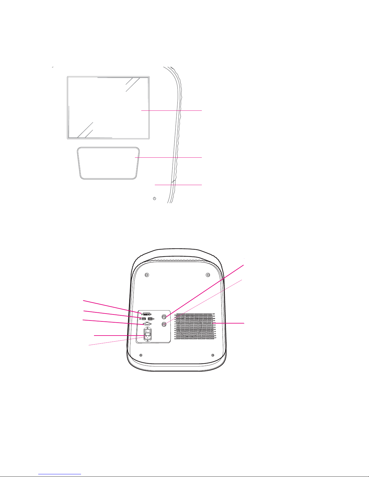
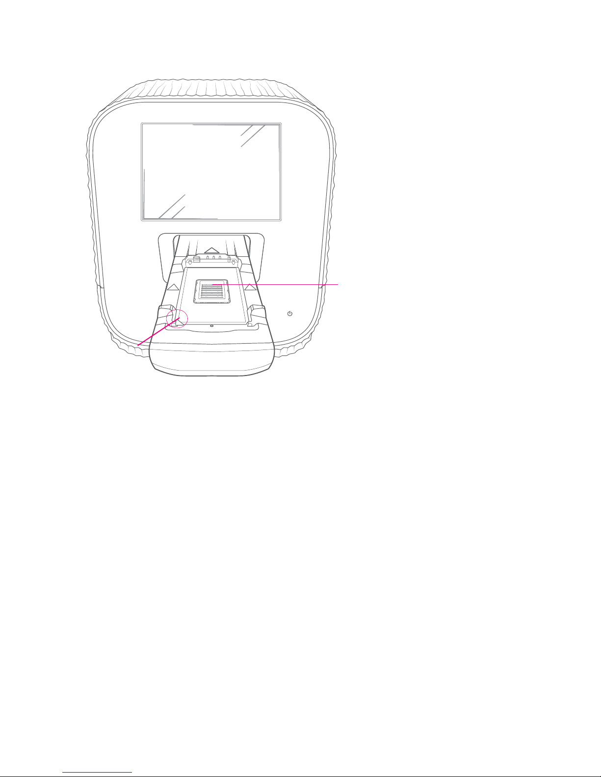
Touchscreen
interface
Retracted tray
Power and
standby indicator
USB 2.0 ports
Ethernet
port
Digital visual
interface
(DVI) port
On/off switch
Power socket
Compressed air input
Exhaust fan
Pre-mixed gas input
Components of the Callisto System
Components of the Callisto System
Figure 1. Front panel of the Callisto instrument
Figure 2. Back panel of the Callisto instrument. There are also two USB 2.0 ports on the side
of the instrument.
8
Callisto System: User Guide
Page 9
Chapter 1: Introducing the Callisto System
White notch
Thermal chuck
Components of the Callisto System
Figure 3. Tray and thermal chuck of the Callisto instrument. The white notch is used to orient
the notched corner of the IFC in the tray. The thermal chuck controls the temperature of the
cells by heating and cooling the IFC.
Callisto System: User Guide
9
Page 10
Chapter 1: Introducing the Callisto System
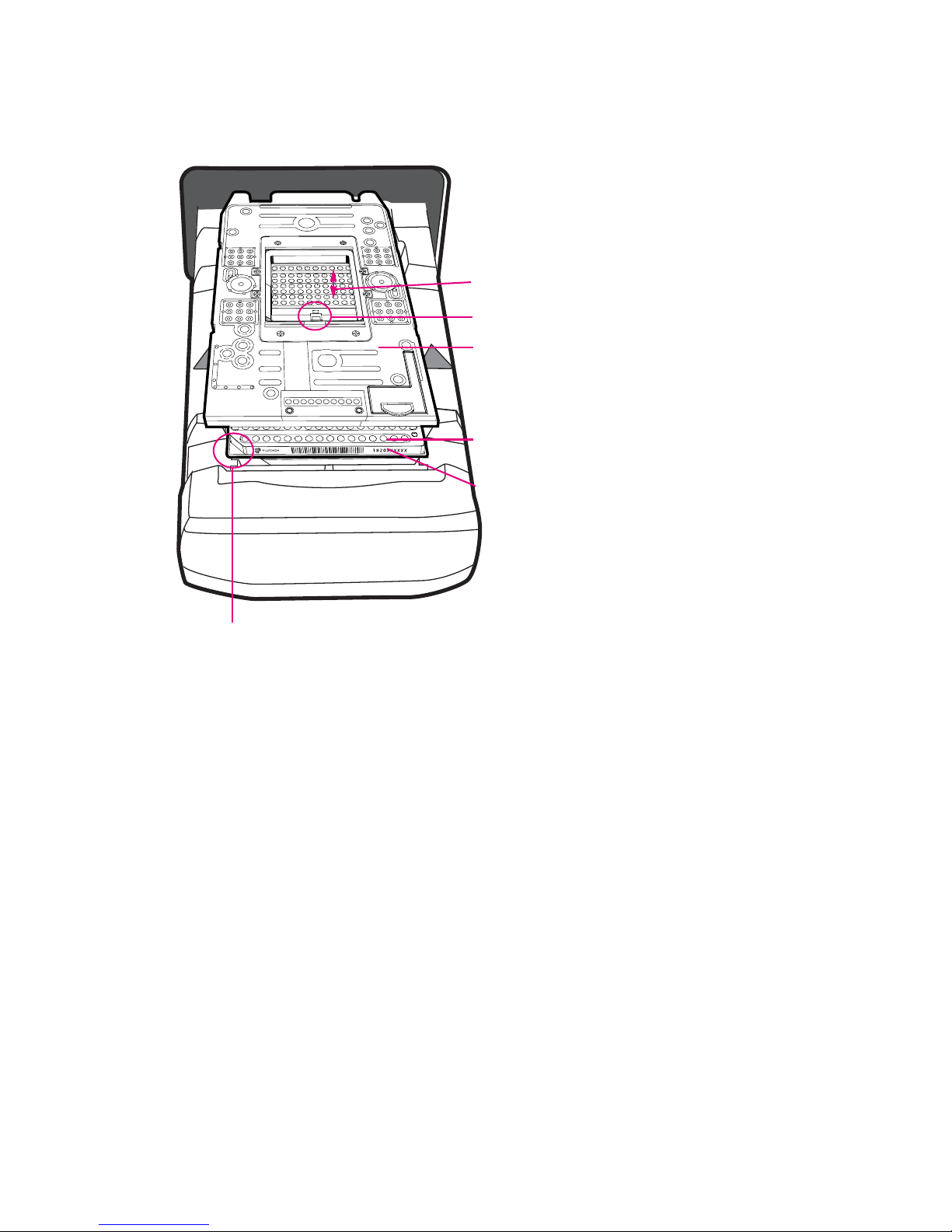
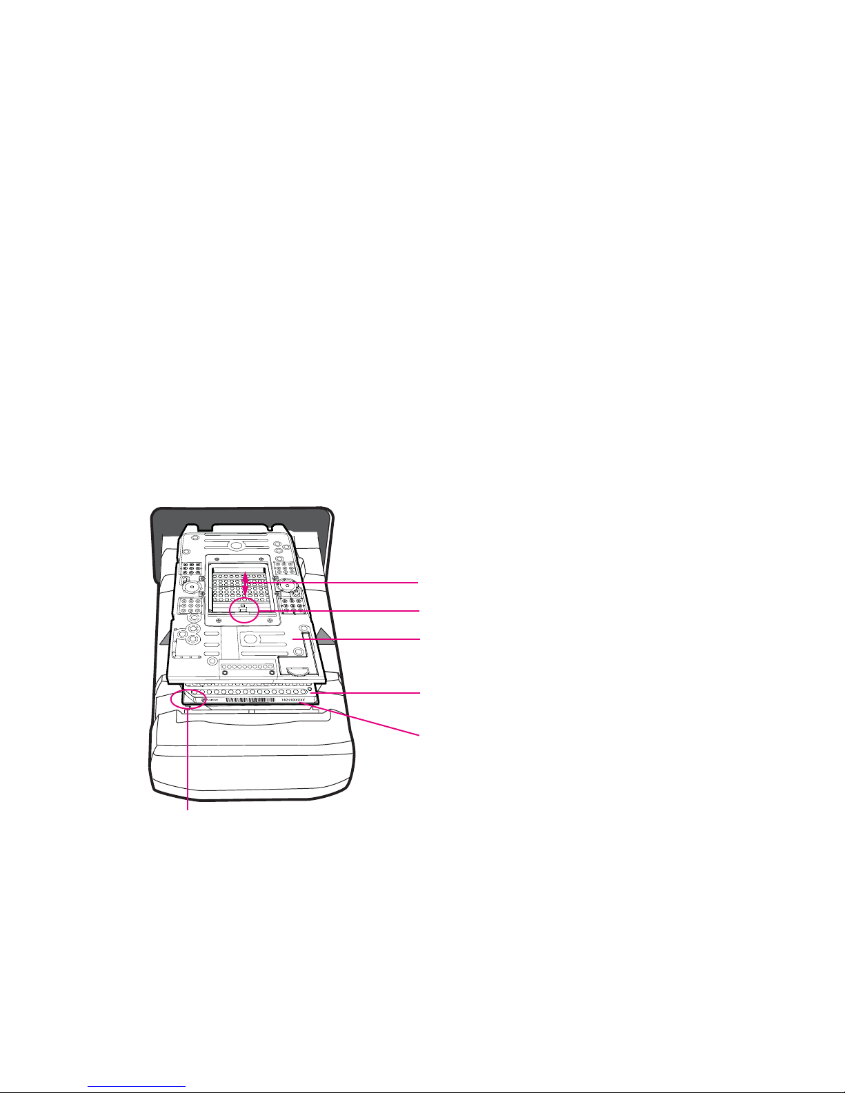
EC interface plate
Callisto Adherent Cell
Culture IFC
Barcode
Environmental chamber
Sensor
White notch
Components of the Callisto System
Figure 4. Exploded view of the Callisto Adherent Cell Culture IFC-environmental control (EC)
interface plate assembly on the Callisto shuttle. The EC interface plate lies on top of the IFC.
Barcode numbers on the IFC label face out. The environmental chamber is the space between
the EC interface plate and the center of the IFC.
10
Callisto System: User Guide
Page 11
Chapter 1: Introducing the Callisto System
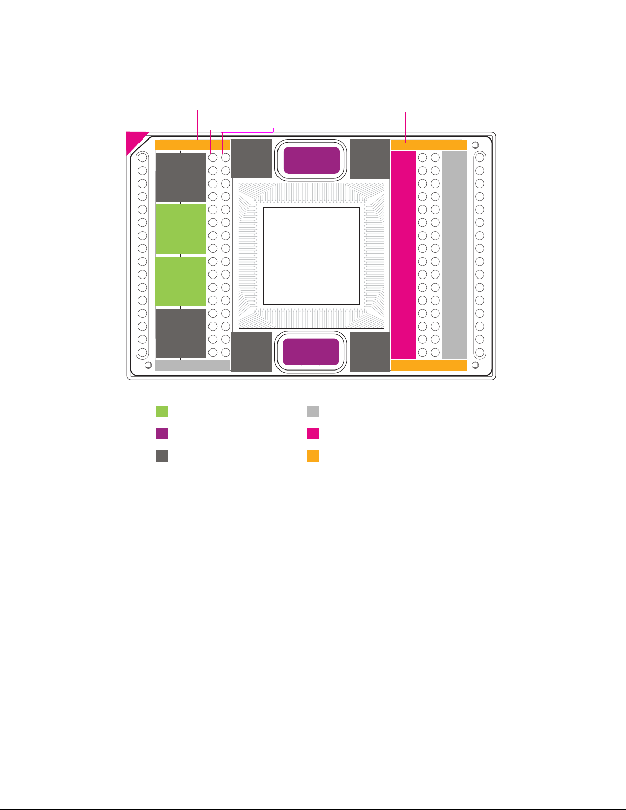
Reagents
Reagents
Hydration
Hydration
Control
Line
Control
Line
Control
Line
Control
Line
Actuation
Actuation
Align Properly
Waste
Harvest
Medium
Medium
Waste
Medium
Reagents
Hydration & Control Line
Actuation
Medium
Harvest
Waste
Medium Bank 1
Medium Bank 2
Medium Bank 3
Cell Inlet 1
Cell Inlet 2
System Software
Figure 5. Callisto IFC loading map for the Callisto Adherent Cell Culture IFC (PN 101-0008)
System Software
Before using this guide, ensure that you have installed or upgraded to Callisto
Experiment Planner v2.0 or later on your computer and Callisto system software v3.8
or later on the instrument. To get the latest system software, go to
fluidigm.com/software.
Callisto System: User Guide
11
Page 12

Chapter 1: Introducing the Callisto System
Components Included in Shipping Box
Components Included in Shipping Box
Component Purpose Qty
1 Callisto system
(PN 100-9911)
2 Power cable, >10 A 2 m,
EC C13 (PN 59000376)
3 Polyurethane tubing,
1/4 inch outside diameter,
clear, 10–20 m
(PN 101-0719)
4 Interface Plate Storage Kit
(PN 101-0576)
5 Callisto Spare Filter Pack
(PN 101-0004)
Automated cell culture system. Includes EC
interface plate.
Country-specific power cable to connect the
Callisto system to the wall socket
Protective conductor terminal (main
ground). It must be connected to
earth ground before any other
electrical connections are made to the
instrument.
Use only power cords provided by Fluidigm or
power cords that meet the minimum ratings of
250V/10A, 16AWG and a length not exceed 2
meters (6 feet).
Connects Callisto to gas cylinder. 1
Stores the EC interface plate when not in use. 1
Replacement filters for the Callisto Adherent
Cell Culture IFC.
1
1
1
NOTE To order additional items, contact Fluidigm sales. For phone or email contact
information, go to fluidigm.com.
User Documentation
The latest Callisto documentation is available for download at
fluidigm.com/documents.
System Functions
The Callisto system enables automated cell culture, dosing, staining, lysis, and
harvesting of cell lysates and live cells. The system is an electrically and
pneumatically operated desktop instrument. It has a built-in environmental controller
to regulate temperature, humidity, and gas. The vacuum pump of the system holds
the IFC in position, and its embedded PC regulates the instrument's functions and
monitors its performance. The system has a touch panel LCD display. All
user-specific instructions and functions can be controlled through the touchscreen.
12
Callisto System: User Guide
Page 13
Chapter 1: Introducing the Callisto System
System Functions
Regulatory Compliance
The following directives and harmonized standards were used to evaluate the safety and performance of
the IFC controller:
General Regulations and Requirements
• 2014/35/EU European Parliament Low Voltage Directive
• 2014/30/EU European Parliament Directive: Electromagnetic Compatibility
Harmonized Standards
• IEC/EN 61326-1
• IEC/EN 61326-2-1
• IEC/EN 61010-1
• IEC/EN 61010-2-010
• IEC/EN 61010-2-081
• UL Standard Number 61010-1 2nd Edition
• CAN/CSA-C22.2 No. 61010-1-04
• CAN/CSA-C22.2 No. 61010-2-010-04
• CAN/CSA-C22.2 No. 61010-2-010-081-04
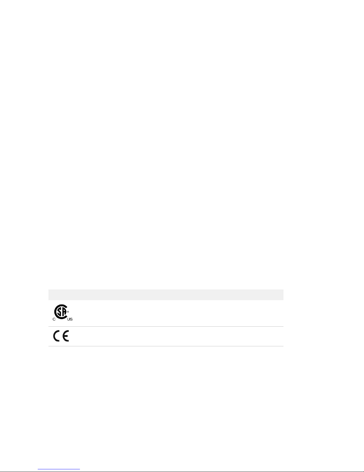
Conformity Symbols on the Instrument
The instrument is labeled with the following conformity markings:
Conformity mark Description
Indicates conformity with safety requirements for Canada and the
United States.
Indicates conformity with European Union requirements for safety and
electromagnetic compatibility.
Refer to Callisto Site Requirements Guide (PN 100-7601) for more detailed
information on the recommended environmental conditions.
AZ
Callisto System: User Guide
13
Page 14

Chapter 1: Introducing the Callisto System
Pre-Mixed Gas Use
Pre-Mixed Gas Use
The Callisto system uses pre-mixed gas to drive microfluidic delivery of reagents to
cells and maintain the gas environment in the IFC. Many experiments require
5% CO
with cell types and experiment designs. Use the pre-mixed gas composition that is
optimized for your experiments and that is within instrument specification. Before
starting an experiment, ensure that the gas cylinder is ≥1/4 full.
To draw compressed gas, attach 1/4 inch outside diameter tubing to the pre-mixed
gas inlet on the back of the system and connect to the pre-mixed gas source. The
allowable pressure input is listed on the back of the Callisto system. For more
information on the allowable pressure input, contact Fluidigm technical support.
and 5–22% O2, balanced by N2. The composition of pre-mixed gas can vary
2
Air Options
The Callisto system uses compressed air to control valves and loading of reagents in
the IFC. The system has an internal compressor to generate compressed air and
draws ambient air by default. Alternatively, in-house compressed clean air can be
connected to supplement the internal compressor. Attach 1/4 inch outside diameter
tubing to the air inlet on the back of the system. The allowable pressure input is
listed on the back of the instrument.
For detailed instructions on enabling use of compressed air, see (Optional) Enable
Compressed Air on page 48.
14
Callisto System: User Guide
Page 15

Chapter 2: Getting Started with Callisto
This chapter describes how to set up and start the Callisto system.
Unpacking and Installing the Callisto
System
WARNING PHYSICAL INJURY HAZARD. Do not attempt to lift or move any
boxed or crated items unless you use proper lifting techniques. The weight
of the crated instrument is 73 kg (160 lb). If you choose to lift or move the
instrument after it has been installed, do not attempt to do so without the
assistance of others. Use appropriate moving equipment and proper lifting
techniques to minimize the chance of physical injury.
Callisto is shipped in one cardboard box containing the system and power cable.
See the Site Requirements Guide (PN 100-7601) for the required site conditions prior
to unpacking and installation of the Callisto system by a Fluidigm service
representative.
If you choose to lift or move the Callisto system after it has been installed, do not
attempt to do so without the assistance of others. Use appropriate moving
equipment and proper lifting techniques to minimize the chance of physical injury.
The uncrated Callisto system weighs approximately 137 lb (62 kg).
You can run the operations described in this section by logging in as Guest. To
perform administrative tasks such as setting data and time or assigning new users,
see Customizing Callisto on page 40.
NOTE Ensure that you have installed the Callisto system software to v3.8 or later on
the instrument. To get the latest system software, go to fluidigm.com/software.
Start the Callisto System
1 Plug the power cable into the power socket.
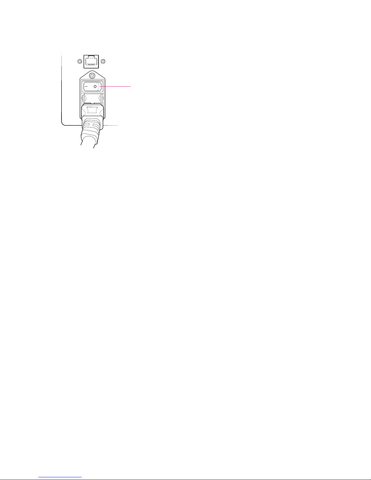
2 Power on the instrument using the switch on the back of the Callisto system:
Callisto System: User Guide
15
Page 16
Chapter 2: Getting Started with Callisto
On/off switch
Start the Callisto System
6
NOTE Switching the back power button on or off turns on or off all components of
the system. In contrast, pushing the front power button for ~2 seconds wakes up the
instrument if it is in sleep mode and prompts the system to display the system
shutdown menu. (See Shut Down the System and the Instrument on page 37.)
16
Callisto System: User Guide
Page 17
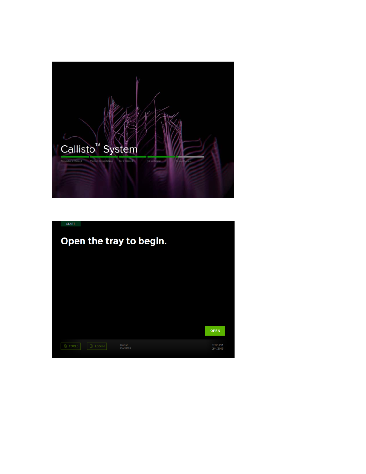
The startup screen displays after 10–15 seconds:
Chapter 2: Getting Started with Callisto
Start the Callisto System
Next, the Start screen displays:
The instrument initializes all system components, including communication protocol,
vacuum and temperature sensors, software parameters, instrument configuration,
calibration data, and the environmental controller.
Callisto System: User Guide
17
Page 18
Chapter 2: Getting Started with Callisto
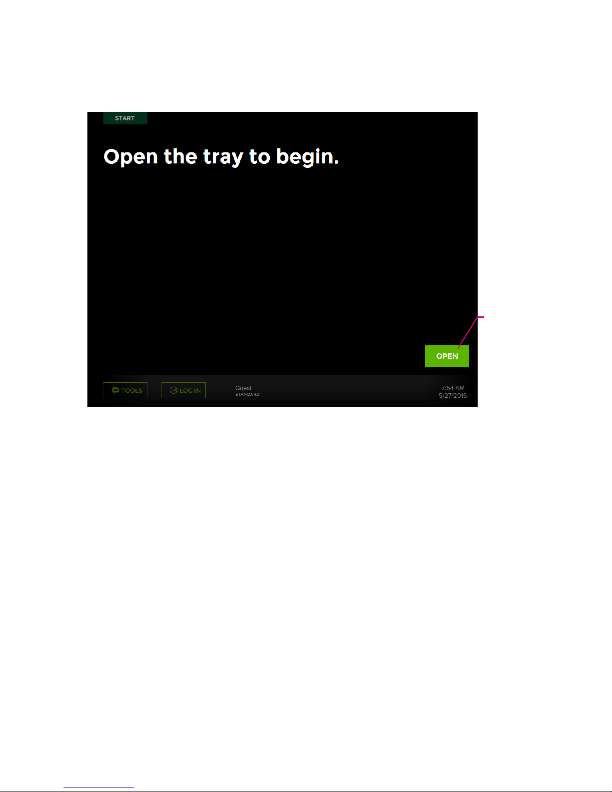
Lime green:
action
How to Use the Callisto Touchscreen
How to Use the Callisto Touchscreen
Figure 6. The Start screen on Callisto. The screen displays normal status in white and typical
actions in light green.
18
Callisto System: User Guide
Page 19
Chapter 2: Getting Started with Callisto
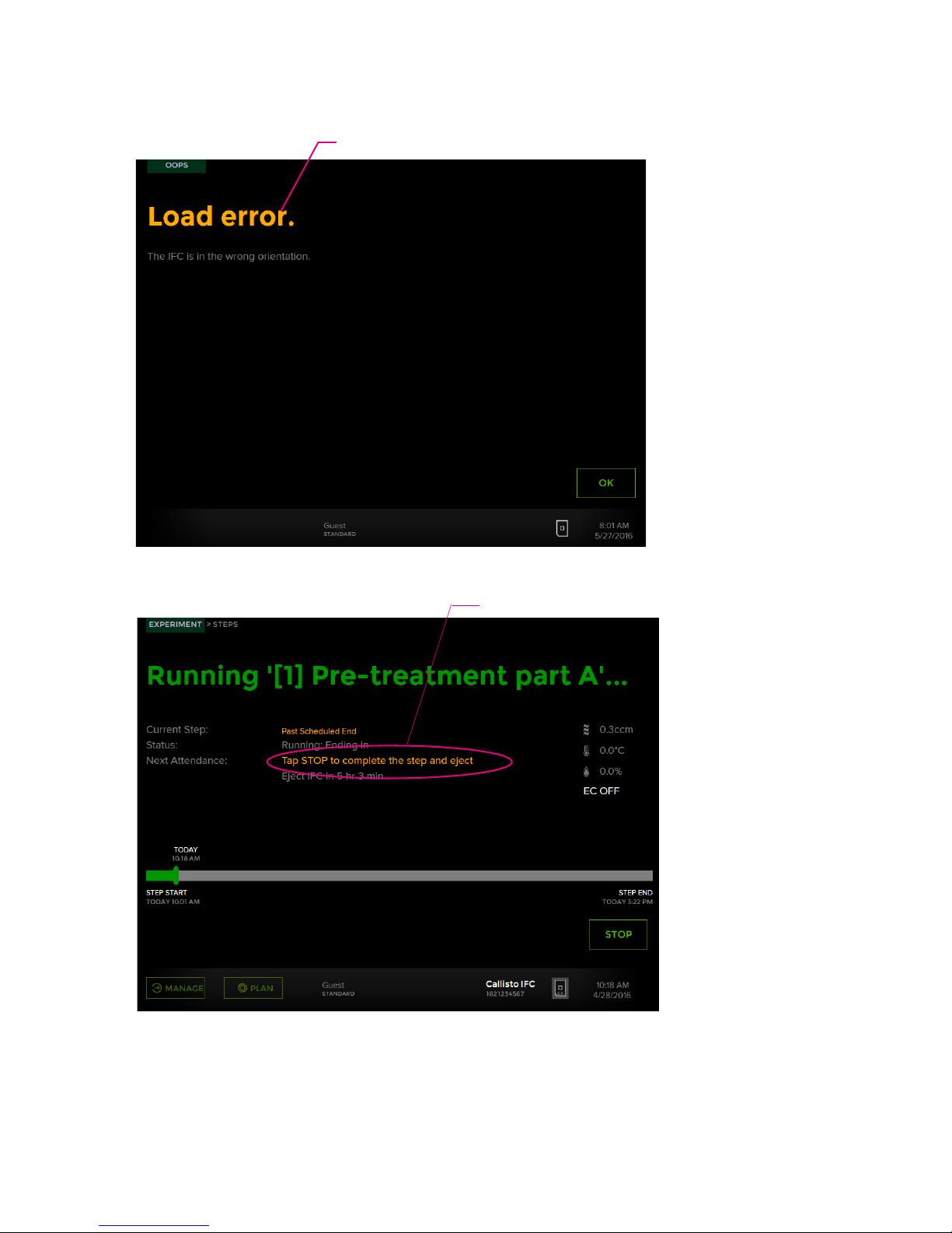
Orange: alert
Orange: notification
How to Use the Callisto Touchscreen
Figure 7. An error screen (top) on Callisto displaying an alert in orange. A notification in
orange (bottom) by Next Attendance. Alerts and notifications also display on the Instrument
Viewer in Callisto Experiment Planner.
Callisto System: User Guide
19
Page 20

Chapter 2: Getting Started with Callisto
A
B
C
D
E
How to Use the Callisto Touchscreen
Figure 8. An example of an Experiment screen that displays while an experiment is running
on Callisto
Location Information
A Gas flow through the IFC-EC interface plate assembly in
3
cm
/min.
B Temperature in the environmental control chamber
C Humidity in the environmental control chamber
D Environmental control is ON or OFF. Display for environmental control
error or warning.
E Next Attendance displays user actions in orange and the time before
remaining reagents are depleted.
20
Callisto System: User Guide
Page 21
Chapter 2: Getting Started with Callisto
EC interface plate
Callisto Adherent Cell
Culture IFC
Barcode
Environmental chamber
Sensor
White notch
Run an Experiment
Load the Callisto Adherent Cell Culture IFC-EC
Interface Plate Assembly in the Instrument
1 If necessary, plug a USB drive containing the experiment plan or execution file into a
USB port of Callisto. [See the Callisto Experiment Planner User Guide
(PN 100-8806).]
2 Prepare the Adherent Cell Culture IFC-EC interface plate assembly (IFC-EC interface
plate assembly) for loading into the instrument (See the Callisto System Getting
Started Guide).
3 Tap OPEN.
4 Place the IFC-EC interface plate assembly onto the tray by aligning the notched
corner of the IFC with the white notch on the tray. Barcode numbers on the IFC label
and the waste sponge slot face out:
Run an Experiment
NOTE Exploded view of the IFC-EC interface plate assembly. To maintain sterility,
keep the IFC and EC interface plate assembled for sterility whenever they are
outside of the cell culture hood.
Callisto System: User Guide
21
Page 22

Chapter 2: Getting Started with Callisto
Run an Experiment
5 Tap LOAD:
The screen of available experiments displays, including published experiments from
Callisto Experiment Planner. If you plugged a USB drive into the instrument, available
experiments to run are displayed. For example:
CAUTION PINCH HAZARD. The instrument door and tray can pinch your
hand. Make sure your fingers, hands, and shirtsleeves are clear of the door
and tray when loading or ejecting an integrated fluidic circuit (IFC).
22
Callisto System: User Guide
Page 23

Chapter 2: Getting Started with Callisto
IMPORTANT
• If a barcode error message displays, check the IFC position and direction, then
reload the IFC. If the instrument still fails to load the IFC, the instrument displays the
Enter IFC barcode screen. Enter the barcode manually, and then tap LOAD.
• If the Callisto Adherent Cell Culture IFC is incorrect or in the wrong orientation, a
Load error screen displays:
Run an Experiment
Select and Run an Experiment
The screen captures are examples. Throughout the procedure, confirm your actions
such as RESUME, PAUSE, EJECT, or STOP (abort a step) by tapping OPEN, CLOSE,
CONFIRM, YES, or OK when prompted.
1 Tap LOG IN to log into Callisto. If these functions are set up by your administrator,
logging into Callisto allows you to receive email notifications and to set remote
access personal identification numbers (PINs). If you will run Callisto as a guest,
proceed to the next step. (See Manage Users on page 41.)
2 Browse the screen to find the appropriate experiment by tapping the tabs at the top
of the screen, or the bars (if displayed) at the bottom left of the screen, or by swiping
across the screen. [To run a modified and validated execution (.iee) file on Callisto,
see Perform Step Operations on page 28.]
Callisto System: User Guide
23
Page 24

Chapter 2: Getting Started with Callisto
Run an Experiment
3 Tap the experiment name to display its Steps screen:
;
4 Verify that the displayed steps of the experiment on the Steps screen match the
experiment plan or modified execution file that was created in Callisto Experiment
Planner. Tap the bars or swipe the screen to scroll through the steps. The
highlighted bar is the step currently running:
5 Ensure that gas flow to the instrument is on and the tank is ≥1/4 full.
6 Tap RUN.
24
Callisto System: User Guide
Page 25

Chapter 2: Getting Started with Callisto
7 From the experiment screen, confirm that you have added reagents and media
according to the appropriate Cell Culture Worksheet. The first pipetting map from
the Cell Culture Worksheets, including the reagents to pipet, displays on the screen:
Run an Experiment
8 Tap CONFIRM. A status bar and the first required step (Pre-treatment Part A) of the
experiment displays. For example:
9 (Optional) During or after a step has run, you can perform certain step operations.
(See Perform Step Operations on page 28.)
Callisto System: User Guide
25
Page 26

Chapter 2: Getting Started with Callisto
Run an Experiment
10 Over the next 3–5 minutes check to ensure that:
• The instrument has started the run.
• There is gas flow and there are no gas flow errors. If there is no gas flow, check to
ensure that the gas line is connected to the instrument and the gas tank is
≥1/4 full.
• The environmental controller is connected. The display says EC ON or EC OFF on
the right side of the screen, which is normal:
If the EC display is orange, see Environmental Control Warnings on page 53.
11 Replenish media and load reagents by following the instructions on the screen and
the Callisto Cell Culture Worksheet. You must follow the on-screen instructions when
“Past scheduled end time” displays. (See Perform Step Operations on page 28.)
Typically, tap PAUSE to refill or change reagents for use in the current or next step.
After filling the IFC, place the IFC-EC interface plate assembly on the instrument tray,
and then tap RESUME. For detailed information on steps, see the Callisto System
Getting Started Guide (PN 100-7599). (Optional) When this function is enabled, tap
PAUSE to perform a task off of the instrument such as imaging the Callisto Adherent
Cell Culture IFC or harvesting materials from the IFC.
12 (Optional) From Callisto Experiment Planner, click Instrument > Launch Instrument
Viewer to remotely monitor the run.
13 (Optional) Modify the experiment. (See Perform Step Operations on page 28.)
26
Callisto System: User Guide
Page 27
Chapter 2: Getting Started with Callisto
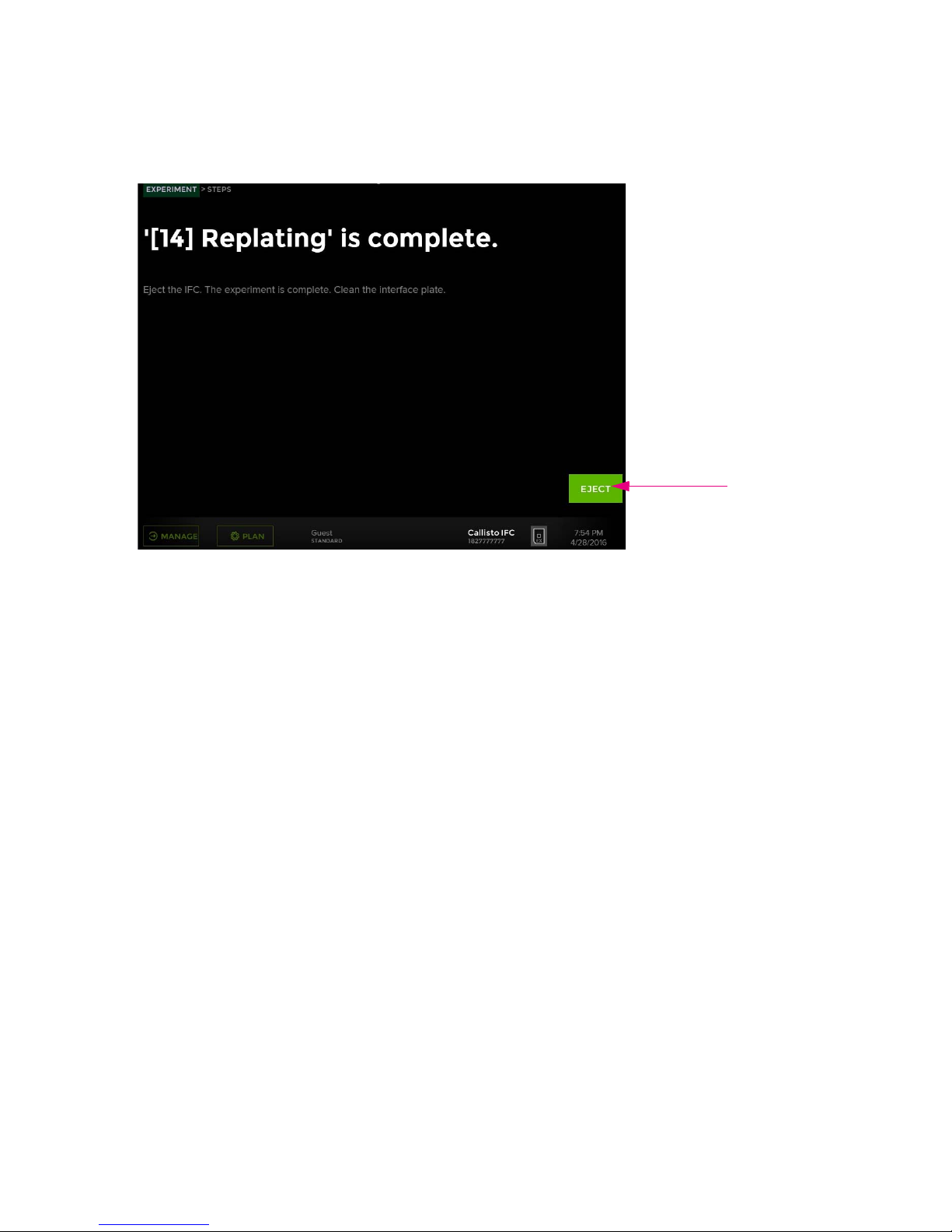
14 At the end of the experiment, tap EJECT to remove the IFC-EC interface plate
assembly:
Run an Experiment
C N
15 Tap CLOSE at the bottom right of the screen to close the tray.
Callisto System: User Guide
27
Page 28

Chapter 2: Getting Started with Callisto
Perform Step Operations
Perform Step Operations
All Steps
Time of
Operation
Before or after
a step is
completed
During a step Abort the step Tap STOP and then YES.
After a step is
completed
If You Want to... Then...
Skip a step. 1 Tap the new step.
2 Tap YES to confirm that you want to skip the current step.
3 Tap RUN and then CONFIRM.
Eject the IFC-EC
interface plate assembly
Tap EJECT.
Feeding and Dosing Steps
Time of
Operation
During a step Refill or change reagents 1 Tap PAUSE to refill or change reagents for use in the current or
During a step Modify the duration of a
If You Want to... Then...
next step.
2 Place the IFC-EC interface plate assembly on the instrument
tray, and then tap RESUME.
1 Tap MODIFY.
step
2 Adjust the duration of the step by moving the slider and then tap
OK.
28
Callisto System: User Guide
Page 29

Chapter 2: Getting Started with Callisto
Modify an Experiment
Time of
Operation
During a step Stop a step to continue
During or after
a step
After a step is
completed
If You Want to... Then...
to the next step
Pause the step 1 Tap PAUSE and then YES to eject the IFC-EC interface plate
Refill or change reagents
past scheduled end time
• Modify the step duration to shorten the run time of the step.
(See Modify the Duration of a Feeding or Dosing Step on
Callisto on page 31) or
• Stop the step, pipet reagents according to the appropriate Cell
Culture Worksheet, and then tap the next step. (See Skip a
Step.)
assembly.
2 Remove the IFC-EC interface plate assembly from the shuttle
and then tap CLOSE.
3 Perform the task, such as refill or change reagents or image the
IFC.
4 Tap OPEN and place the IFC-EC interface plate assembly on the
shuttle.
5 Tap RESUME and then YES.
Modify or add a step. (See Modify an Experiment.)
Modify an Experiment
You can modify an experiment before, during, or after a run on Callisto. For example,
while an experiment is running, export the experiment [the experiment (.iee) file],
modify it in Experiment Planner, and then import the modified experiment to Callisto
while it is still running the experiment. The modified experiment is run after the
current step is finished.
• Skip a Step
• Modify the Duration of a Feeding or Dosing Step on Callisto on page 31
• Modify an Experiment Remotely on page 32
• Modify an Experiment with a USB Drive on page 32
Skip a Step
You can skip to run a single or multiple steps after the current step or you can re-run
the step previous to the current step. You can only go back one step. For example,
you can stop a step that is currently running, re-pipet reagents according to the
appropriate Cell Culture Worksheet, and then run the previous step. Callisto
Experiment Planner displays skipped and repeated steps.
Callisto System: User Guide
29
Page 30

Chapter 2: Getting Started with Callisto
Modify an Experiment
IMPORTANT You cannot skip Pre-treatment part A, Pre-treatment part B, or Cell
loading steps. These steps are required to proceed with the experiment on Callisto.
1 If desired, stop a step or wait between steps to skip a step.
2 Tap the previous or proceeding step from the current step (shaded) to skip a step.
For example, tap [4] Cell attachment or [6] Transfection to skip a step:
The Change Step screen displays to confirm skipping a step.
3 Ensure that you have pipetted reagents in the IFC according to the appropriate Cell
Culture Worksheet for that step.
4 On the Change Step screen, tap YES and then tap RUN.
5 On the Experiment screen, confirm that the pipetting map and reagents match the
appropriate Cell Culture Worksheet, and then tap CONFIRM. Callisto continues the
run at the selected step from the skipped step.
30
Callisto System: User Guide
Page 31

Chapter 2: Getting Started with Callisto
Modify the Duration of a Feeding or Dosing Step on
Callisto
1 On the Steps screen, while a step is running, tap MODIFY.
2 Adjust the duration of the step by moving the slider, and then click OK. The
instrument returns to the Steps screen and updates the screen according to the
changed duration:
Modify an Experiment
Callisto System: User Guide
31
Page 32

Chapter 2: Getting Started with Callisto
Modify an Experiment
Modify an Experiment Remotely
For complete instructions and to network the software to Callisto, see the Callisto
Experiment Planner User Guide (PN 100-8806). To set the personal identification
number for instrument access, see Set a Personal Identification Number (PIN) to
Access the Instrument Remotely on page 36.
Modify an Experiment with a USB Drive
You can modify an experiment during or after a run on Callisto. During a run, you can
only modify uncompleted steps.
IMPORTANT If you have removed the IFC from the instrument after a completed run
for an extended period of time, cell viability and biological response may be
affected.
1 Plug a USB drive into a USB port of Callisto.
NOTE The Callisto instrument software supports only one USB drive plugged into
the instrument at a time. Ensure that only a single USB drive with the file of interest is
plugged into a port on the side or back of the instrument.
2 To export the experiment file from the instrument:
• During a run: On the bottom left of the Steps screen, tap MANAGE and then tap
Export Experiment. A screen confirms that Callisto successfully exported the
experiment that is running to the USB drive.
• After a run: On the bottom left of the Start screen, tap TOOLS > Manage
Experiments, and then tap Export Experiment. When the Export screen displays,
tap the experiment to export. A screen confirms that the export to the USB drive
was successful.
3 Plug the USB drive into a USB port of a computer with Callisto Experiment Planner
installed, and then open the execution (.iee) file.
4 (Optional) Click the Execute tab to review completed and uncompleted steps.
5 Click the Summary tab and then click Unlock for Editing:
32
Callisto System: User Guide
Page 33

Chapter 2: Getting Started with Callisto
6 Modify and validate the execution (.iee) file and save it to the USB drive.
IMPORTANT
• If you change culture chamber replicates, you must reselect chambers to harvest
cell lysates and cells.
• You can reassign a cell culture chamber to a different replicate chamber group
until different treatments are applied to the two replicate chamber groups.
• You must update the original execution file in order to resume the experiment on
Callisto with the modified file under the same filename.
7 Click the Cell Culture Worksheets tab, and then print and/or save the PDF of the
Cell Culture Worksheets for reference. The Cell Culture Worksheets contain a
summary report, a screen capture of the experiment, and pipetting maps and
instructions for all steps.
8 Plug the USB drive with the modified execution (.iee) file into a USB port on Callisto.
9 To import the experiment file to the instrument:
• During a run. On the Steps screen, tap MANAGE > Import Experiment. Select the
experiment and tap YES to confirm importing the modified experiment. Callisto
runs the modified experiment at the next uncompleted step.
• After a run. On the Start Screen, tap TOOLS > Manage Experiments, and then tap
Import Experiment. The Manage screen displays. Tap the modified file to import
it. On the Experiments screen, tap the modified experiment file. A screen confirms
the import was successful. On the Experiments screen, tap the experiment to run
it.
Modify an Experiment
IMPORTANT
If importing the execution (.iee) file fails,
because...
The .iee file was not validated in Callisto
Experiment Planner.
The experiment was resumed after export
but before importing the modified .iee file.
Then...
Validate the .iee file in Callisto Experiment
Planner and import the .iee file again.
Pause the current run and export the .iee file.
Modify and import it.
10 (Optional) On the bottom left of the Steps screen of Callisto, tap PLAN. Tap PLAN
VIEW or CALENDAR VIEW to review the schedule or calendar:
• In Calendar view, view events according to date and relative time of day.
Tap a date to view an hourly schedule in Plan view according to step.
• In Plan view, steps and events display by time of day. Tap a step tab to view the
schedule of events. Active steps are highlighted.
NOTE Callisto displays the modified experiment with a revision number; for
example, “Rev. 2.” After every modification of the same experiment, Callisto
increments the revision number.
Callisto System: User Guide
33
Page 34
Chapter 2: Getting Started with Callisto
Import and Export Experiment Plans and Execution Files
Import and Export Experiment Plans and
Execution Files
1 Plug a USB drive into a USB port of Callisto.
2 On the Start screen, tap TOOLS.
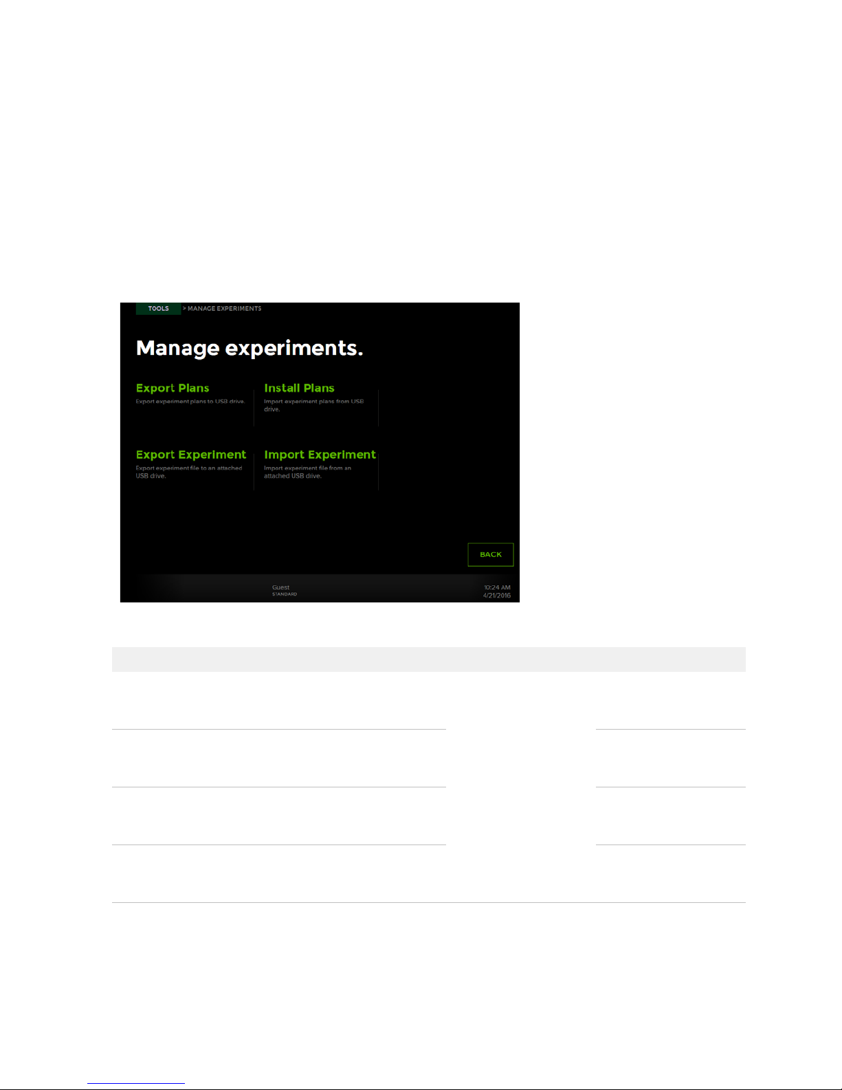
3 On the Tools screen, tap Manage Experiments. The Manage Experiments screen
displays:
4 Import or export files as required:
If you want to ... Tap ... And then ... To perform these tasks
Export an experiment plan Export Plans
Export an execution file Export Experiment Modify the execution file
Import an experiment plan Import Plans Run an experiment on
Import an execution plan Import Experiment Run a modified
Select a file to export to
a USB drive or import
from a USB. The
software confirms the
export or import.
34
Modify the experiment
plan or use the plan on
another instrument.
in Callisto Experiment
Planner.
Callisto from the
instrument.
execution plan on
Callisto.
Callisto System: User Guide
Page 35

Chapter 2: Getting Started with Callisto
NOTE You can also import and export experiment files to a USB drive by tapping
MANAGE during an experiment and then tapping Export Experiment or Import
Experiment. You do not need to log in as an administrator.
View System Information
1 On the Start screen, tap TOOLS.
2 On the Tools screen, tap About This System. On the Diagnostics screen, you can
view the system ID, supported IFCs, and firmware and software versions.
View System Information
Export a Log
1 Plug a USB drive or equivalent storage device into a USB port on the side or back of
the instrument. Wait a few seconds for the instrument to recognize the USB drive.
2 On the Start screen, tap TOOLS.
3 On the Tools screen, tap About This System.
4 On the About screen, tap EXPORT LOG. The instrument confirms it has exported the
log to the USB drive. The log is in a .logpak file.
5 Unplug the USB drive from the instrument.
NOTE Another way to export a log file is while a step is running. Tap MANAGE and
then tap Export Log. The instrument exports the .logpak file to the USB drive.
Callisto System: User Guide
35
Page 36

Chapter 2: Getting Started with Callisto
View Experiment Runs
View Experiment Runs
1 On the Start screen, tap TOOLS.
2 On the Tools screen, tap Experiment Runs. The Experiment Runs screen displays
the history of experiments run according to year:
3 (Optional) Tap an experiment name to display name, category, status, start, and last
run.
Set a Personal Identification Number
(PIN) to Access the Instrument Remotely
A PIN restricts access to Callisto from Callisto Experiment Planner. Remote access
from Callisto Experiment Planner allows you to view instrument status from the
software instrument viewer and open experiment plan (.iep) and execution (.iee) files.
1 Ensure that remote access is enabled. (See Enable Remote Access on page 47.)
2 During an experiment, tap MANAGE and then tap Set Pin.
3 Enter a PIN of up to eight digits and then tap APPLY.
36
Callisto System: User Guide
Page 37

Chapter 2: Getting Started with Callisto
Sort and Show Experiments
1 On the Load screen, tap TOOLS.
2 On the Tools screen, tap Preferences.
3 On the Preferences screen, you can tap the radio button to sort experiments (.iep
and .iee files) alphabetically or chronologically or tap a radio button to show all
experiments or the most recently used experiments from the last 60 days:
Sort and Show Experiments
Shut Down the System and the
Instrument
Perform the system shutdown procedure to safely shut down the computer system
before turning off the instrument power.
1 Press and hold the power and standby indicator on the lower right front of the
instrument for ≥2 seconds until the System screen displays. (See Components of the
Callisto System on page 8.)
Callisto System: User Guide
37
Page 38

Chapter 2: Getting Started with Callisto
Shut Down the System and the Instrument
2 Tap YES to proceed with system shutdown. When the system powers down, the
computer shuts down:
NOTE
• If the system is busy, a screen displays a message to wait until an experiment
completes running before trying to power down the system again.
• If you must power down the system due to an unrecoverable error, record the error
code and tap SHUTDOWN. The computer shuts down (the screen goes dark).
Report the error code to Fluidigm technical support.
3 Wait 10 seconds (the screen goes dark). The computer shuts down only.
4 Toggle the power switch on the back of the instrument to off. This shuts down all
components of the system.
5 Verify system and instrument shutdown by noting the power and standby indicator:
Instrument State Screen Power and Standby
Indicator
Normal operation On Lit
Sleep mode Off Blinking
After system shutdown Off Lit
After power shutdown Off Off
NOTE The instrument enters sleep mode if no experiment is running and is idle for
>1 hour. To exit sleep mode, touch the screen.
38
Callisto System: User Guide
Page 39

Chapter 2: Getting Started with Callisto
Shut Down the System and the Instrument
6 To restart the system, toggle the power switch to on. (See Start the Callisto System
on page 15.)
Callisto System: User Guide
39
Page 40

Chapter 3: Customizing Callisto
Callisto requires that you log in as an administrator in order to manage users and
files, update the system, and change date and time.
Log In
1 Tap LOG IN at lower left of the Start screen. The Log In screen displays.
2 Tap Admin in the appropriate tab (box) to log in as administrator, or log in with a
specific user account.
3 If you log in as the administrator, tap Admin below the tabs (boxes). You do not need
a password:
Log Out
1 On the Load screen, tap LOG OUT.
2 On the Log In screen, tap LOG OUT.
40
Callisto System: User Guide
Page 41

Chapter3:Customizing Callisto
Manage Users
Add or edit users by changing settings under Manage Users.
1 Ensure that you have logged in to the system as administrator. (See Log In on
page 40.)
2 On the Load screen, tap TOOLS. The TOOLS button displays only when an
experiment is not running.
3 On the Tools screen, tap Manage Users. The Manage Users screen displays with the
available user accounts:
Manage Users
4 Tap ALL or ADMIN to display all accounts or the administrator account.
5 (Optional) Tap NEW USER.
Callisto System: User Guide
41
Page 42

Chapter 3: Customizing Callisto
Manage Users
6 Tap STANDARD or ADMIN, and then tap the edit button:
7 A keyboard displays. Enter the user name and tap OK:
8 Next to Password, tap the edit button.
9 After the keypad displays, enter the user password, tap OK, and then SAVE.
42
Callisto System: User Guide
Page 43

Chapter3:Customizing Callisto
10 (Optional) Set up email for the new user. The instrument emails alerts to the user
when the Callisto Adherent Cell Culture IFC needs attention (for example, feeding) or
if there is an error with the EC interface plate.
a To use email notification, ensure that the Callisto instrument is on a network and
remains connected to the network during an experiment run. The network connector
is on the back of the instrument.
NOTE Contact your information technology (IT) department to bring Callisto online.
Ask the IT department for SMTP server and SMTO port information.
b Under Email, tap the edit button for each field, and enter this information:
Field Entry
Name User name on new account
Password Alphanumeric and special characters
SMTP server Contact IT
SMTP port Contact IT
Manage Users
Recipient email Person who needs to receive alerts. Separate email addresses
by a semicolon.
Sender email Email account from which you want to send email
c Tap VERIFY EMAIL. The new user receives an email to confirm email setup. If
verification fails, the software retries in ~3 minutes. If the email is verified, the screen
displays “verified”:
NOTE If the email is not verified, contact your information technology department.
d Tap SAVE.
Callisto System: User Guide
43
Page 44

Chapter 3: Customizing Callisto
Change the Date and Time
11 (Optional) Edit existing user accounts by tapping the user name. For example, to
remove a user, tap the user name and tap REMOVE.
Change the Date and Time
1 Ensure that you have logged in to the system as administrator. (See Log In on
page 40.)
2 On the Load screen, tap TOOLS.
3 On the Tools screen, tap Preferences. On the Preferences screen, the current date
and time display.
4 To edit the date and time, tap the edit button:
44
Callisto System: User Guide
Page 45

5 Tap CHANGE TIME ZONE to set the correct time zone for the location of the
instrument:
Chapter3:Customizing Callisto
Change the Date and Time
6 Tap OK.
Callisto System: User Guide
45
Page 46

Chapter 3: Customizing Callisto
Update the System
7 Select a date format, and slide a value up or down to adjust the date and time. Tap
OK:
:
Update the System
1 Copy the appropriate update package (.pak) to a USB drive.
2 Plug the USB drive into a USB port of the instrument.
3 (Optional) On the Start screen, tap TOOLS to note the current version of the system
software.
4 Ensure that you have logged in to the system as administrator. (See Log In on
page 40.)
5 On the Load screen, tap TOOLS.
6 On the Tools screen, tap About This System.
7 On the About screen, tap UPDATE SYSTEM.
46
Callisto System: User Guide
Page 47

8 On the Update System screen, tap UPDATE:
Chapter3:Customizing Callisto
Enable Remote Access
The instrument reboots and displays the Start screen.
9 Tap TOOLS to ensure that the instrument installed the appropriate system software
version.
10 Unplug the USB drive from the instrument.
Enable Remote Access
Enable and disable remote access to Callisto from Callisto Experiment Planner. If
Enable Remote Access is unchecked (disabled), in Callisto Experiment Planner, you
will not be able enter a personal identification number (PIN) to access Callisto, view
instrument status on the instrument viewer, or open files from the instrument.
IMPORTANT Enable Remote Access is enabled by default.
1 Ensure that you have logged in to the system as administrator. (See Log In on
page 40.)
2 On the Load screen, tap TOOLS.
3 On the Tools screen, tap Preferences.
Callisto System: User Guide
47
Page 48

Chapter 3: Customizing Callisto
Compressed air input
(Optional) Enable Compressed Air
4 Tap the check box by Enable Remote Access to check the box and enable access or
tap the checked box to disable access:
(Optional) Enable Compressed Air
1 Ensure that you have logged in to the system as administrator. (See Log In on
page 40).
2 Connect 1/4 inch outside diameter tubing to the air inlet at the back of the Callisto
system:
3 From the system software, tap Tools.
4 Tap Preferences.
48
Callisto System: User Guide
Page 49

5 For compressed air input, under Alternate Air Input, tap Enabled:
Chapter3:Customizing Callisto
(Optional) Enable Compressed Air
Callisto System: User Guide
49
Page 50

Appendix A: Troubleshooting
For troubleshooting the Callisto Adherent Cell Culture IFC, preventive maintenance,
and instructions, see the Callisto System Getting Started User Guide (PN 100-7599).
For troubleshooting the Callisto Experiment Planner, see the Callisto Experiment
Planner User Guide (PN 100-8806).
Observation and Possible Course of
Action
Powering On and Off
Observation Possible Cause Recommended Action
Callisto™ system failed to
power on
No display after power is
turned on and fan is
running
No display after power is
turned on and fan is not
running
• System check error
• Unrecoverable error
No AC power • Verify that the power cable is properly connected to the
power socket and the instrument.
• Verify that the power socket has power.
• Verify that the toggle switch on the back of the
instrument is in the on position.
• Check and if necessary replace the fuse. (See Fuse
Replacement on page 59.)
Callisto system in sleep
mode
Callisto system power
supply not fully reset
Error during system
calibration
Touch the screen or push the front power button for
~2 seconds to wake up the instrument. The system
shutdown screen displays, which you can cancel by tapping
NO. The system enters sleep mode when the start screen is
displayed and there is no user input for 1 hour.
Turn off the Callisto system power switch on the back
panel. Wait 10 seconds and reboot by turning on the power
switch. All components power on.
Reboot the system. If the system fails to recover, contact
Fluidigm technical support and note any error codes.
50
Callisto System: User Guide
Page 51

Loading
Observation Possible Cause Recommended Action
Appendix A: Troubleshooting
Observation and Possible Course of Action
Message: “Load error.
Insufficient vacuum.
Clean the thermal chuck
or load an IFC, and try
again.”
Message: “Load error:
The IFC is in the wrong
orientation.”
Message: “Enter IFC
barcode.”
• Message: “Unable to
load.”
• Message: “Load
error. The IFC is not
detected.”
• Message: “Install
interface plate error.”
Dirty IFC or thermal
chuck surface
IFC-EC interface plate
assembly placed
incorrectly on the tray
Optical character
recognition failed to
read barcode on IFC
• EC interface plate or
IFC missing
• EC interface plate not
loaded correctly
• EC interface plate not
functioning properly
• Wrong EC interface
plate
Clean the thermal chuck surface and the back of the IFC
with 70% ethanol or 70% isopropyl alcohol and a lint-free
cleaning cloth. Reload the IFC.
Place the ejected assembly correctly on the tray. The
notched corner of the IFC should align with the white notch
on the tray.
• Ensure that the IFC barcode faces you.
• Enter barcode manually in the Enter IFC barcode
screen.
• Use the EC interface plate with the Callisto Adherent
Cell Culture IFC. (See Components of the Callisto
System on page 8.) If necessary, tap OPEN to remove
the incorrect IFC, then reload the correct IFC by tapping
LOAD.
• Position the ejected IFC-EC interface plate assembly
correctly. Ensure that the notched corner of the IFC
aligns with the white notch on the tray.
• Eject the IFC-EC interface assembly and restart the
system.
• Contact technical support.
Message: “An
unrecoverable error is
detected.”
Various 1 Record the displayed error code.
2 Tap SHUTDOWN to shut down the system, which shuts
down the computer (the screen goes dark).
3 Wait 10 seconds, and then toggle the power switch on
the back of the instrument to off.
4 To restart the system, toggle the power switch to on.
(See Start the Callisto System on page 15.)
NOTE For complete instructions on system shutdown,
see Shut Down the System and the Instrument on
page 37. If the unrecoverable error persists, contact
Fluidigm technical support.
Callisto System: User Guide
51
Page 52

Appendix A: Troubleshooting
Observation and Possible Course of Action
Running
Observation Possible Cause Recommended Action
• Experiment plan not
available for
selection
• Message: “No USB
drive is found.”
Gas not flowing when
environmental control is
on (≤0.3 cm
3
/min)
Malfunctioning USB • Use a new USB drive.
• Check if there is a second USB drive in the instrument. If
there is, remove it.
USB drive is not properly
formatted or is not
recognized
Experiment plan (.iep
file) or execution (.iee)
file not validated
• Leak
• Loose fitting
• Reformat the USB drive or use a different USB.
• Reinsert the USB drive in the instrument.
• Insert the USB drive into a different port.
Return to Callisto Experiment Planner and validate the
experiment plan or execution file. Select the validated plan
on Callisto.
• Check gas line connections.
• Check valves.
• Regulator valve not
open
• Tank empty Replace the tank only when the instrument is not running. A
full tank with 300 ft
3
gas lasts ~1 month. If the tank empties
significantly sooner, check the regulator.
52
Callisto System: User Guide
Page 53

Appendix A: Troubleshooting
Observation and Possible Course of Action
Environmental Control Warnings
The environmental control is the system that regulates the temperature, humidity,
and gas in the space between the center of the IFC and the EC interface plate. If
there are irregularities in the environmental control, Callisto warns you. To allow time
for Callisto to verify a warning, the instrument emails notification of an environmental
control warning 10 minutes after the instrument first detects a potential problem.
))
Observation Possible Cause Recommended Action
High ambient
temperature
Gas flow too weak Gas tank empty Replace the gas tank.
Gas flow too strong Malfunctioning valve 1 Wait a few minutes to see if the gas flow decreases.
Humidity too low Environmental control is
Humidity too high Environmental control is
Temperature too low • Environmental
Temperature too high • Environmental
Laboratory is too warm Cool the room temperature to 15–28 ºC (59–82 ºF).
2 Restart the instrument. If the problem persists, call
Fluidigm technical support.
Rehydrate the humidity sponge with 1.8 mL water or
dry
wet
control plate or its
sensor is too cool
• Temperature drop
during a harvest step
control plate or its
sensor is too warm
• Laboratory is too
warm
replace the sponge with a new hydrated one.
The humidity is high likely due to a harvest step when the
temperature is high in the IFC-EC interface plate assembly.
Wait until the harvest is complete to see if normal
conditions are restored.
Wait until the harvest is complete to see if normal
conditions are restored. If the problem persists, call
Fluidigm technical support.
Cool the room temperature to 15–28 ºC (59–82 ºF).
Message: “EC
detached.”
Callisto System: User Guide
Defective sensor on EC
interface plate
Eject and reload the EC interface plate. If the problem
persists, call Fluidigm technical support.
53
Page 54

Appendix B: Maintenance,
Decontamination, and Disposal
Cleaning and Maintenance
This section describes how to clean and maintain your Callisto system for optimal
performance.
Before using a cleaning or decontamination method other than those recommended
by Fluidigm, verify with Fluidigm technical support that the proposed method will not
harm the instrument.
Clean the Thermal Chuck
We recommend cleaning the thermal chuck between experiments on Callisto.
1 Allow the system to cool down by waiting at least 5 minutes after the completion of a
run protocol.
WARNING HOT SURFACE HAZARD. The thermal cycler chuck gets hot
and can burn your skin. Use caution when working near the chuck.
WARNING HOT SURFACE HAZARD. Never press down on the integrated
fluidic circuit (IFC) when it is on the thermal cycler chuck. If you encounter a
vacuum problem, turn off the system, allow it to cool down, and remove the
IFC. Clean the bottom of the IFC and/or chuck surface with a lint-free cloth
and 70% isopropyl alcohol.
CAUTION HOT SURFACE HAZARD. Make sure the chuck has had time to
cool. It can get very hot and cause burn injury.
2 Tap OPEN on the Start screen.
3 Remove the IFC from the tray.
4 Moisten a lint-free cleaning cloth or soak lint-free cleaning swabs with 70% ethanol
or 70% isopropyl alcohol.
WARNING BIOHAZARD. If you are putting biohazardous material on the
instrument, use appropriate personal protective equipment and adhere to
Biosafety in Microbiological and Biomedical Laboratories (BMBL), a
publication from the Centers for Disease Control and Prevention, and to
your lab's safety protocol to limit biohazard risks. If biohazardous materials
are used, properly label the equipment as a biohazard. For more
54
Callisto System: User Guide
Page 55

Appendix B: Maintenance, Decontamination, and Disposal
Vacuum hole
information, see the BMBL guidelines online at cdc.gov/biosafety/
publications/index.htm.
5 With the cleaning cloth or cleaning swabs, remove debris from the thermal chuck by
gently wiping towards the vacuum holes according to the pattern of the chuck. Next,
wipe along the perimeter of the chuck:
Clean the Thermal Chuck
Cleaning the Cell Culture EC Interface Plate
We recommend cleaning the EC interface plate:
• Every time that you remove the EC interface plate from the instrument. Disassemble
the EC interface plate from the IFC and clean the EC interface plate in a cell culture
hood.
• Before you store an EC interface plate in the Interface Plate Storage Kit.
Use the cleaning swabs and lint-free cleaning cloths supplied in the Callisto
Accessories Kit (PN 101-0003).
Callisto System: User Guide
55
Page 56

Appendix B: Maintenance, Decontamination, and Disposal
Sensor
Clean the Thermal Chuck
1 Use a pre-moistened lint-free wipe supplied with the instrument to gently wipe the
face of the EC interface plate, where the sensor is attached and pointing up, to clean
it:
IMPORTANT Do not touch the sensor.
2 Spray a cleaning swab with 70% ethanol or 70% isopropyl alcohol:
IMPORTANT Do not spray alcohol directly on the EC interface plate.
56
Callisto System: User Guide
Page 57

Appendix B: Maintenance, Decontamination, and Disposal
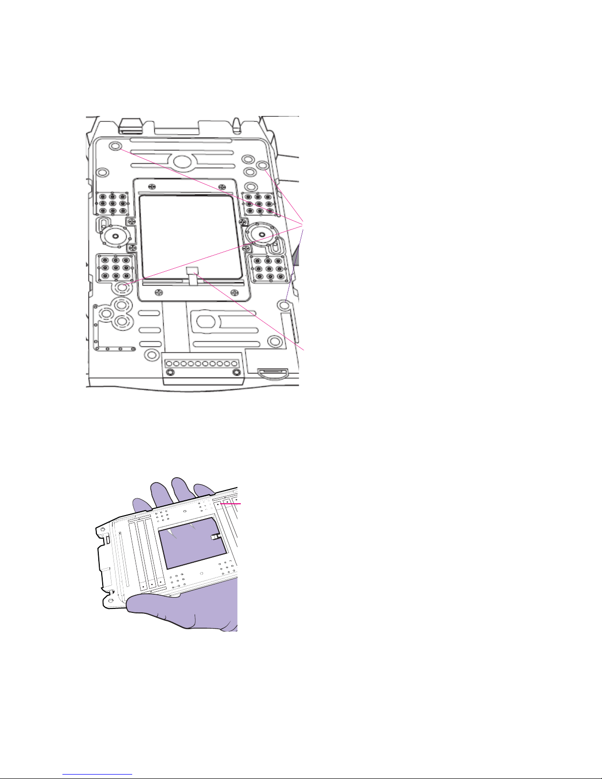
Waste Medium bank zone
Medium bank zone Sensor
3 Gently clean the IFC-facing side of the EC interface plate with the cleaning swab,
including the medium bank zones:
Clean the Thermal Chuck
Replacing Filters in the EC Interface Plate
Replace filters in the EC interface plate filter if:
• The EC interface plate is suspected of being contaminated. Replace the filters in the
contaminated area.
• The Callisto Adherent Cell Culture IFC is contaminated. Replace all filters in the EC
interface plate.
• A filter is wet. A wet filter appears darker than dry filters.
Use the filters and ejectors from the Callisto Spare Filter Pack (PN 101-0004). Use a
cleaning swab from the Callisto Cleaning Kit, which is included in the Callisto
Accessories Kit (PN 101-0003).
1 Clean gloved hands with 70% ethanol or 70% isopropyl alcohol.
Callisto System: User Guide
57
Page 58
Appendix B: Maintenance, Decontamination, and Disposal
Filters on top side of EC interface
plate
Sensor pointing down
Push ejector into the correct hole
on sensor side of EC interface
plate to remove the filter.
Clean the Thermal Chuck
2 Locate the contaminated or wet filter on the top side of the EC interface plate
(sensor pointing down):
3 Flip the EC interface plate to the sensor side (sensor pointing up).
4 Insert the ejector into the hole where the wet filter is located and then push out the
used filter from the EC interface plate:
5 Appropriately discard the used filter.
6 With a gloved hand, insert a new filter into the empty hole on top of the EC interface
plate. Both sides of the filter are identical.
58
Callisto System: User Guide
Page 59

Appendix B: Maintenance, Decontamination, and Disposal
7 With a cleaning swab, gently push the filter to secure the new filter in place.
Cleaning the Touchscreen
Wipe down the touchscreen with a lint-free cleaning cloth as needed.
IMPORTANT
• Do not spray cleaning solution directly on the touchscreen, as it may penetrate the
seams around the screen and cause damage. Spray cleaning solution on a lint-free
cleaning cloth and then gently wipe the instrument surface.
• Do not use bleach to clean the instrument as it is corrosive to metal.
• Before using a cleaning or decontamination method other than those
recommended by Fluidigm, verify with Fluidigm technical support that the
proposed method will not damage the equipment.
Preventive Maintenance
Preventive Maintenance
For optimal performance of your Callisto system, we recommend:
• Performing annual maintenance by a certified Fluidigm service technician.
• Only using replacement parts supplied by Fluidigm.
Disposal of IFCs
Dispose of used IFCs in accordance with federal, state, regional, and local laws for
hazardous waste disposal.
Fuse Replacement
No fuse replacement is required during installation. If either of the power fuses is
found to be faulty, replace both fuses:
1 Toggle the main power switch on the rear of the instrument OFF, and unplug the
instrument from the wall outlet.
2 Remove the fuse holder from the inlet power switch by pushing and releasing the
fuse holder blocks.
Callisto System: User Guide
59
Page 60

Appendix B: Maintenance, Decontamination, and Disposal
Fuse Replacement
3 Replace both fuses (8 A, 250 V type, time-lag T fuse), and reinstall the fuse holder.
Follow the arrow marks in the fuse holder to match the casing.
4 Plug the instrument into the wall outlet, and toggle the main power switch ON.
60
Callisto System: User Guide
Page 61

Appendix B: Maintenance, Decontamination, and Disposal
Decontamination of the Callisto System
Decontamination of the Callisto System
Ensure that the Callisto system is cleaned and/or decontaminated prior to servicing
the equipment, removing it from use, or transporting it for disposal. Refer to the
instructions contained in this document and use only those materials specified.
Biological Agents
1 Using a soft cloth, apply 70% ethyl alcohol or 70% isopropyl alcohol to all accessible
surfaces.
2 Keep surfaces wet for at least 5 minutes, then wipe dry.
3 Repeat steps 1 and 2 once.
4 Clean all decontaminated surfaces with a wet cloth to remove residual alcohol and
wipe dry.
Hazardous Chemicals
1 Using a soft cloth, apply 70% ethyl alcohol or 70% isopropyl alcohol to all accessible
surfaces.
IMPORTANT Before use, ensure that alcohol is compatible with the chemicals used.
2 Keep surfaces wet for at least 5 minutes, and then wipe dry.
3 Repeat steps 1 and 2 once.
4 Clean all decontaminated surfaces with a wet cloth to remove residual alcohol and
wipe dry.
Radioactive Materials
1 Using a soft cloth, apply an industry-standard radioactivity decontaminant to all
accessible surfaces.
2 Wipe the surfaces as directed by the decontaminant manufacturer.
3 Survey the instrument with an appropriate radioactivity measuring device.
4 Ensure that the survey results are at or below background level.
Callisto System: User Guide
61
Page 62

Appendix C: Related Documentation
Document Title Part Number
Protocols and User Guides
Callisto User Guide 100-7598
Callisto Getting Started Guide 100-7599
Callisto Site Requirements Guide 100-7601
Callisto System Usage (Quick Reference) 100-7715
Callisto Experiment Planner User Guide 100-8806
Callisto Site Installation Guide 100-7597
Run the Callisto System Test 001-A Protocol 101-0681
Run the Standard Pressure Test (SPT) with the Universal Pressure Test Fixture (uPTF) Protocol 101-0759
62
Callisto System: User Guide
Page 63

Appendix D: Safety
IMPORTANT For translations of the instrument safety information, see Safety
Information for Genomics Instruments (PN 101-6810).
General Safety
In addition to your site-specific safety requirements, Fluidigm recommends the
following general safety guidelines in all laboratory and manufacturing areas:
• Use personal protective equipment (PPE): safety glasses, fully enclosed shoes, lab
coats, and gloves, according to your laboratory safety practices.
• Know the locations of all safety equipment (fire extinguishers, spill kits, eyewashes/
showers, first-aid kits, safety data sheets, etc.), emergency exit locations, and
emergency/injury reporting procedures.
• Do not eat, drink, or smoke in lab areas.
• Maintain clean work areas.
• Wash hands before leaving the lab.
Instrument Safety
The instrument should be serviced by authorized personnel only.
WARNING Do not modify this instrument. Unauthorized modifications may
create a safety hazard.
WARNING BIOHAZARD. If you are putting biohazardous material on the
instrument, use appropriate personal protective equipment and adhere to
Biosafety in Microbiological and Biomedical Laboratories (BMBL), a
publication from the Centers for Disease Control and Prevention, and to
your lab's safety protocol to limit biohazard risks. If biohazardous materials
are used, properly label the equipment as a biohazard. For more
information, see the BMBL guidelines online at cdc.gov/biosafety/
publications/index.htm.
WARNING PHYSICAL INJURY HAZARD. Do not attempt to lift or move any
boxed or crated items unless you use proper lifting techniques. The weight
of the crated instrument is 73 kg (160 lb). If you choose to lift or move the
instrument after it has been installed, do not attempt to do so without the
assistance of others. Use appropriate moving equipment and proper lifting
techniques to minimize the chance of physical injury.
Callisto System: User Guide
63
Page 64

Appendix D: Safety
Instrument Safety
WARNING PINCH HAZARD. The instrument door and tray can pinch your
hand. Make sure your fingers, hands, and shirtsleeves are clear of the door
and tray when loading or ejecting an integrated fluidic circuit (IFC).
WARNING HOT SURFACE HAZARD. The thermal cycler chuck gets hot
and can burn your skin. Use caution when working near the chuck.
WARNING HOT SURFACE HAZARD. Never press down on the integrated
fluidic circuit (IFC) when it is on the thermal cycler chuck. If you encounter a
vacuum problem, turn off the system, allow it to cool down, and remove the
IFC. Clean the bottom of the IFC and/or chuck surface with a lint-free cloth
and 70% isopropyl alcohol.
WARNING HOT SURFACE HAZARD. Make sure the chuck has had time to
cool. It can get very hot and cause burn injury.
Symbols on the Instrument
Symbol English
Caution, risk of danger
Consult the manual for further safety information.
Hot surface hazard. Do not touch; potential for personal injury.
Biohazard.
Electricity hazard. Indicates high electricity levels and a threat of electric shock from machines and/or
equipment in the vicinity. You may suffer severe injuries or death.
Pinch hazard. Indicates where pinch hazards exist. Exercise caution when operating around these
areas.
Lifting hazard.
Indicates specific chemical harm.
Indicates hazardous, toxic, or very toxic materials that are very hazardous to health or potentially fatal
when inhaled, swallowed, or in contact with the skin.
Indicates a health hazard.
Power and standby symbol.
64
Callisto System: User Guide
Page 65

Symbol English
Appendix D: Safety
Instrument Safety
Power switch is in the On position.
Power switch is in the Off position.
Protective conductor terminal (main ground). It must be connected to earth ground before any other
electrical connections are made to the instrument.
To minimize negative environmental impact from disposal of electronic waste, do not dispose of
electronic waste in unsorted municipal waste.
Follow local municipal waste ordinances for proper disposal provision. Contact customer service for
information about responsible disposal options.
Callisto System: User Guide
65
Page 66

Appendix D: Safety
Electrical Safety
Electrical Safety
WARNING ELECTRICAL HAZARD. DO NOT REMOVE THE COVERS.
Electrical shock can result if the instrument is operated without its
protective covers. No internal components are serviceable by the user.
WARNING ELECTRICAL HAZARD. Plug the instrument into a properly
grounded receptacle with adequate current capacity.
Chemical Safety
The responsible individuals must take the necessary precautions to ensure that the
surrounding workplace is safe and that instrument operators are not exposed to
hazardous levels of toxic substances. When working with any chemicals, refer to the
applicable safety data sheets (SDSs) provided by the manufacturer or supplier.
66
Callisto System: User Guide
Page 67

For technical support visit fluidigm.com/support.
 Loading...