

Page 1
IFU 004 User Guide Issue 4
Page 2

Fluidic Analytics products have been designed to be safe in accordance with the operating instructions. If the equipment is not
used in the manner specified in the operating manual the equipment may be impaired and warranty may be void, warranty
exclusions include:
• Defects caused by improper operation or opening of the manifold.
• Repair or modification done by anyone other than Fluidic Analytics or an authorized agent.
• Damage caused by accident or misuse.
• Damage caused by disaster.
• Corrosion due to use of improper sample.
The information contained in this manual is subject to change without notice. Fluidic Analytics shall not be liable for errors
contained herein or for incidental or consequential damages in connection with the performance, or use of this material. This
document contains information that is protected by copyright. All rights are reserved. No part of this document may be
photocopied, reproduced, or translated to another language without prior written consent of Fluidic Analytics.
Document reference: IFU004 Issue 4
Page 3

1
General information ................................................................................................................................... 3
Safety information ..................................................................................................................................... 4
2.1. Hazard summary ............................................................................................................................................. 5
2.2. Noise.................................................................................................................................................................... 5
2.3. Ventilation and air extraction ...................................................................................................................... 5
2.4. Chemical safety ................................................................................................................................................ 6
2.5. Manual handling .............................................................................................................................................. 6
2.6. Power requirements ....................................................................................................................................... 6
Instrument specifications.......................................................................................................................... 7
3.1. Fluidity One Instrument Purpose ............................................................................................................... 7
3.2. Chips ................................................................................................................................................................... 7
3.3. Reagent cartridge............................................................................................................................................ 8
User Training ............................................................................................................................................... 9
Installation ................................................................................................................................................... 9
5.1. Dimensions and required operating space ............................................................................................. 9
5.2. Instrument location ......................................................................................................................................... 9
5.3. Transportation and handling ..................................................................................................................... 10
5.4. Preparing the instrument ............................................................................................................................ 10
5.5. Operating conditions .................................................................................................................................... 10
5.6. Connections .................................................................................................................................................... 10
Operation .................................................................................................................................................. 12
6.1. Manual checks ................................................................................................................................................ 12
6.2. Turning on and off ........................................................................................................................................ 12
6.3. Pipetting onto chips ..................................................................................................................................... 13
6.4. Loading chips ................................................................................................................................................. 13
6.5. Replacing reagent cartridges .................................................................................................................... 14
6.6. Starting the measurement .......................................................................................................................... 15
6.7. Calibration ....................................................................................................................................................... 17
Instrument priming ................................................................................................................................. 17
Viewing Results ....................................................................................................................................... 18
Shut down ................................................................................................................................................ 20
User Accounts .......................................................................................................................................... 20
Results storage and download ............................................................................................................. 20
11.1. How to download results....................................................................................................................... 20
11.2. File formats available for results download ..................................................................................... 21
Cleaning .................................................................................................................................................... 21
Service, Maintenance and Fault Repairs ............................................................................................. 21
Decommissioning and storage ............................................................................................................. 21
Contacting customer support ............................................................................................................... 21
Page 4

2
Page 5

3
General information
This manual details the installation, maintenance and ownership of the Fluidity One
instrument produced by
Fluidic Analytics Limited
Unit A The Paddocks Business Centre
Cherry Hinton Road
Cambridge
CB1 8DH
UK
This manual provides a guide for the installation and upkeep of the Fluidity One by trained
service personnel and users. All users must familiarise themselves with the safety guidelines
and general operation information sections of this manual prior to use.
The software described in this manual is version 2.2
Page 6

4
Safety information
WEEE Directive (2012/19/EU)
For professional users in the European Union
If you wish to discard electrical and electronic equipment (EEE), please contact Fluidic
Analytics Ltd for further information.
The Fluidity One contains a Lithium Coin Cell Battery with the following warnings:
REACH Regulation (EC) No 1907/2006
Substances of Very High Concern (SVHC) Information
This product has been found to contain SVHC:
1,2-dimethoxyethane, ethylene glycol dimethyl ether (EGDME)
CAS number:
110-71-4
The product is compliant with the following directives (provided it is
used with the supplied peripheral components):
• The Radio Equipment Directive (2014/53/EU)
• Safety Testing EN 61010-1:2010
• EMC Testing EN 61326-1:
Warning: This is a Class A product. In a domestic environment this product may
cause radio interference in which case the user may be required to take adequate
measures.
• The Restriction of Hazardous Substances in Electronic Equipment Directive
(2011/65/EU) (RoHS)
Page 7
5
2.1. Hazard summary
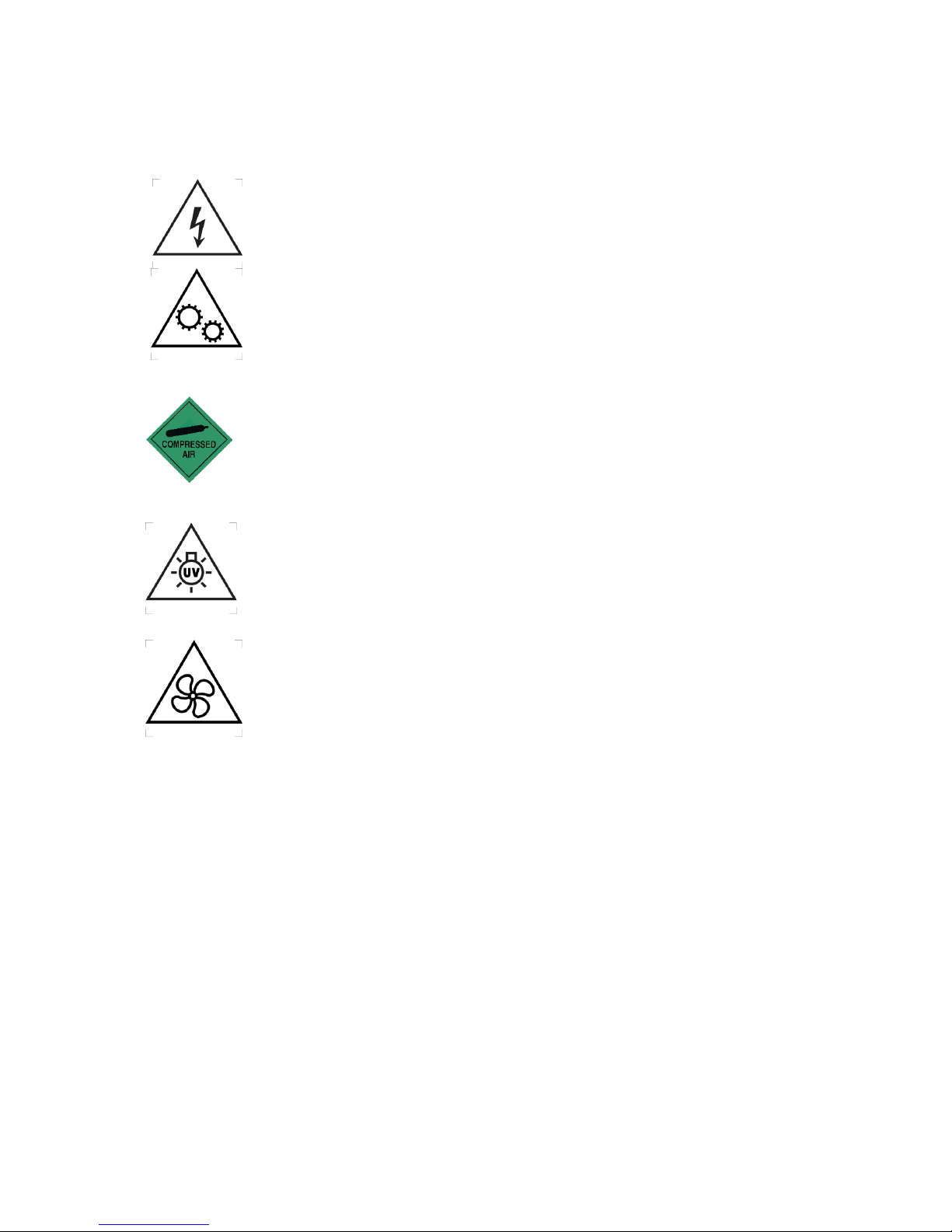
The following hazards are present on the Fluidity One instrument:
The operator must not remove any covers or open any electrical enclosures,
or power supply units, on or supplied with the machine. Lethal voltages are
present in these enclosures and the Fluidity One contains automatically
controlled moving mechanisms where there is a danger of fingers being
crushed
The Fluidity One uses an in built air compressor to control liquid movement
through the instrument.
The Fluidity One contains a UV light source. This does not present a danger
to users provided the unit is not opened.
The Fluidity One contains a fan. This does not present a danger to users
provided the unit is not opened.
2.2. Noise
Testing was carried out on the instrument to measure airborne noise emissions. No specific
precautions are required when using this instrument with regards to noise.
2.3. Ventilation and air extraction
If this instrument is being used with toxic chemicals that could pose a risk to the user
(should they come in contact with them or their vapours) the instrument should be operated
inside a suitable fume cupboard. Assessment of the risks of chemicals and reagents for use
with the instrument is the sole responsibility of the user. Compatibility of the user’s
chemicals with the Fluidity One is the responsibility of the user.
Page 8

6
2.4. Chemical safety
Any toxic chemicals used with the Fluidity One instrument are the responsibility of the user.
Refer to the Materials Safety Data Sheet provided with the reagent cartridge for hazards
associated with the reagent cartridge (Reference: MSDS001)
2.5. Manual handling
The Fluidity One weighs 16 kg and should be carried with the appropriate level of care.
2.6. Power requirements
The power pack is usable from 100-240VAC, 50-60Hz. The unit requires an earth. Only use
the power lead supplied with the unit.
Page 9
7
Instrument specifications
3.1. Fluidity One Instrument Purpose
The Fluidity One uses Microfluidic Diffusional Sizing to size and quantify unlabelled, native
protein in solution in less than 15 minutes. This can be used in a laboratory environment for
routine protein sizing, protein quality analysis, study of protein conformation, aggregation or
oligomerization and analysis of protein interactions.
3.2. Chips
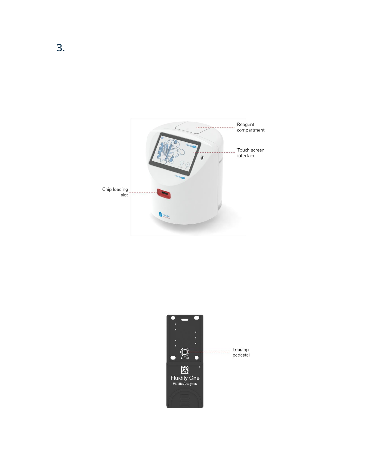
Samples are loaded sequentially into the Fluidity One using disposable microfluidic chips.
The chips are made of Cyclic Olefin Copolymer (COC), manufactured using injection
moulding and include a loading pedestal for the pipetting of 5-10 µL of sample. The chip is
validated for single use.
Chips may be disposed of in a similar manner to other biohazardous laboratory waste.
Page 10
8
3.3. Reagent cartridge
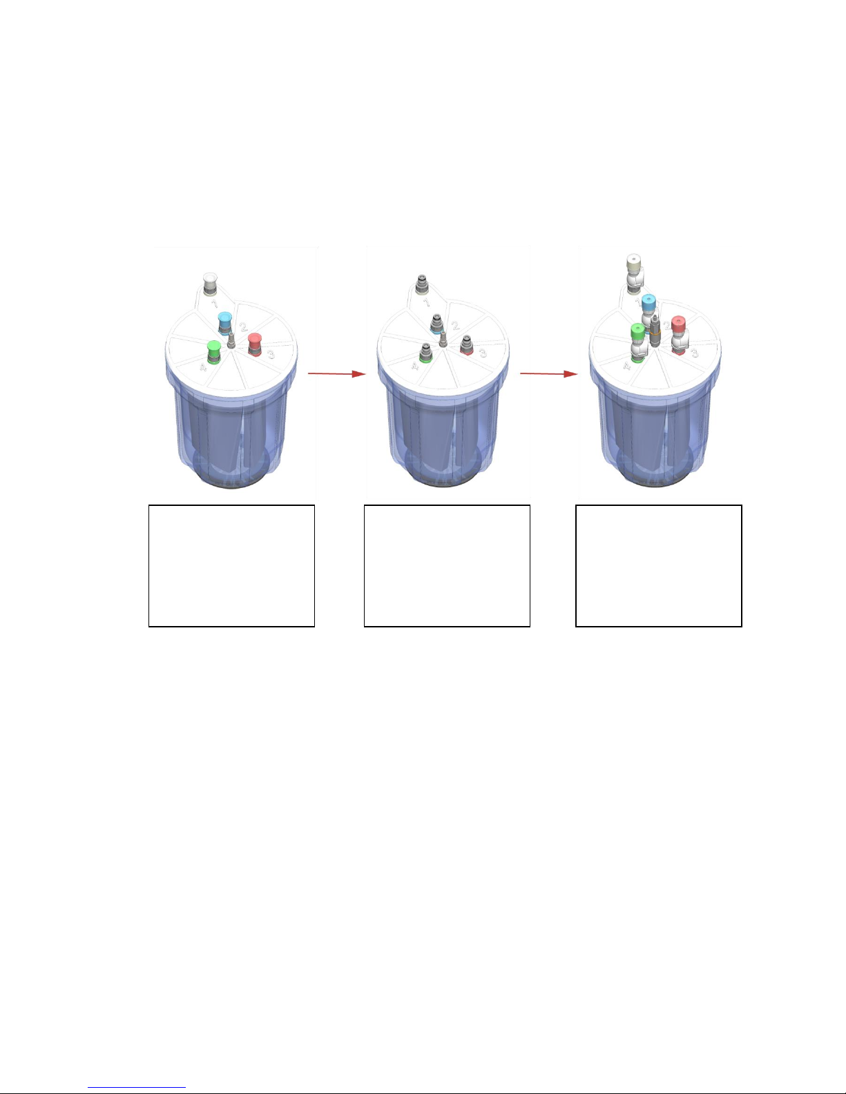
Reagent cartridges are supplied with colour coded connections and can be connected to the
Fluidity One instrument as shown.
Do not disconnect the reagent cartridge while an experiment is running.
Reagent cartridges are disposable and should not be re-filled by users.
For full instructions on changing a reagent cartridge, see section 6.5.
New cartridge
Blanking caps cover
each port and must be
removed before use.
Connection ports
Colour coded to match
the hoses in the
instrument.
Connected cartridge
The connectors at the
end of each hose click
onto the cartridge
ports.
Page 11
9
User Training
Please speak to your Fluidic Analytics contact for guidance on user training.
Installation
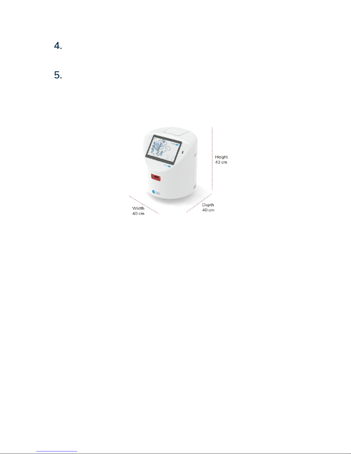
5.1. Dimensions and required operating space
The dimensions of the instrument are shown below.
5.2. Instrument location
The Fluidity One is designed for use on a flat laboratory bench.
Prior to placing the instrument ensure the work surface on which the instrument is to be
placed is clear and clean.
Do not place the Fluidity One adjacent to instruments that could cause excessive vibrations,
such as centrifuges, vortex mixers etc.
Page 12
10
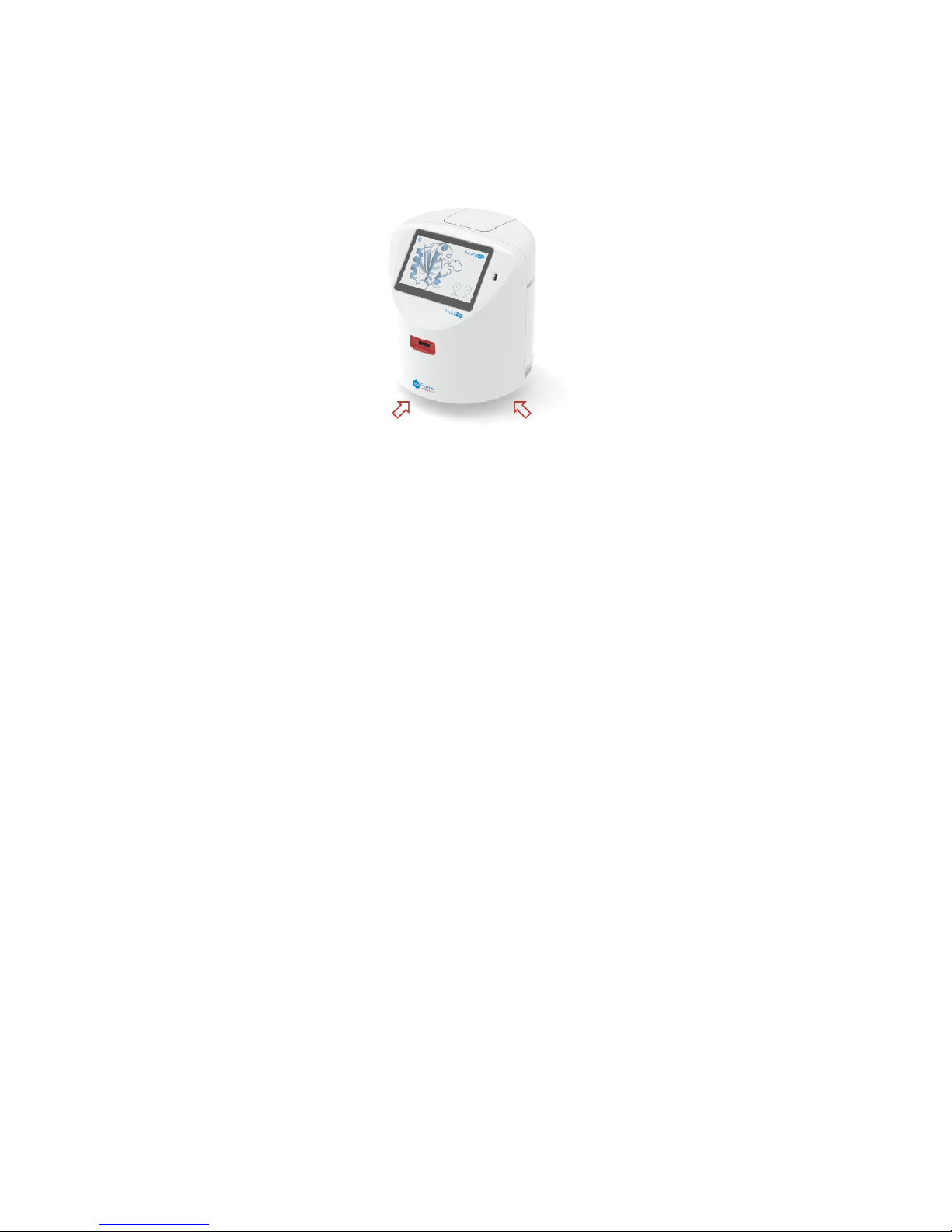
5.3. Transportation and handling
Lift the instrument carefully from underneath as indicated on the diagram below.
5.4. Preparing the instrument
Ensure the instrument is placed on a stable, secure, flat and dry work surface.
Remove all outer packaging from the instrument.
5.5. Operating conditions
The instrument should be operated at room temperature (15-25°C)
Take care to position it away from other equipment which may give off excessive heat, e.g.
fridges, freezers, refrigerated centrifuges or thermal cyclers.
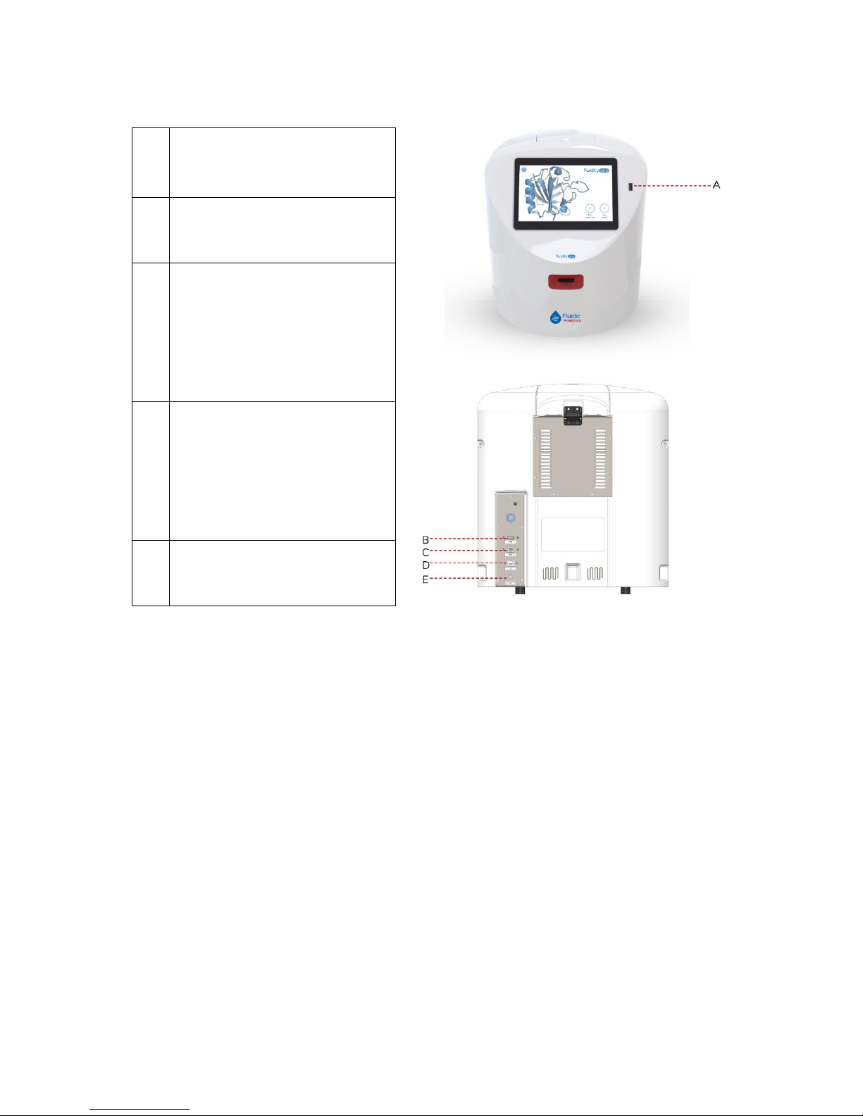
5.6. Connections
The Fluidity One connections are made as shown below.
Page 13
11
A
Front USB port to download
results
B
Rear USB port to download
results
C
Rear USB 2.0 B port – for use by
Fluidic Analytics engineers
during assessment only.
D
Ethernet connection – can be
used to connect the instrument
to a network where WiFi is not
available.
E
Mains power supply – must be
plugged in to an earthed power
supply.
Page 14
12
Operation
6.1. Manual checks
Check the instrument to ensure there is no packaging material present.
Connect the reagent cartridge as shown in section 6.5.
Ensure there is no obstruction in the chip insert slot.
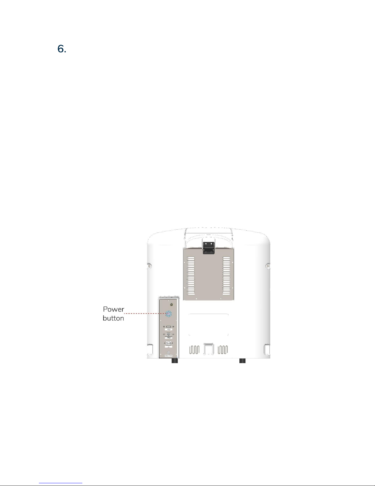
6.2. Turning on and off
Connect the power supply to the instrument, then to the mains.
To turn the instrument on, press the power button on the back of the instrument. This
button is illuminated blue when the instrument is on.
To turn the instrument off, press and hold the power button for 5 seconds.
Page 15
13
6.3. Pipetting onto chips
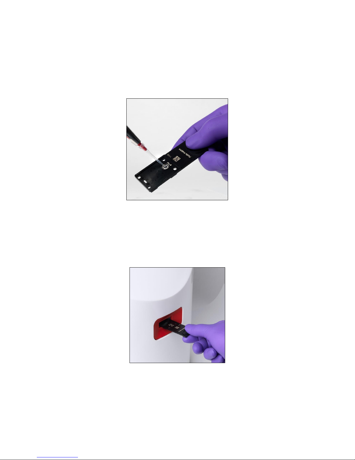
The pedestal indicated in the picture below can accept 5-10 µL of sample. A larger volume
can lead to overflow and incorrect insertion of the sample onto the chip. If overflow occurs,
discard the chip and perform the test again.
5 µL is the recommended volume.
6.4. Loading chips
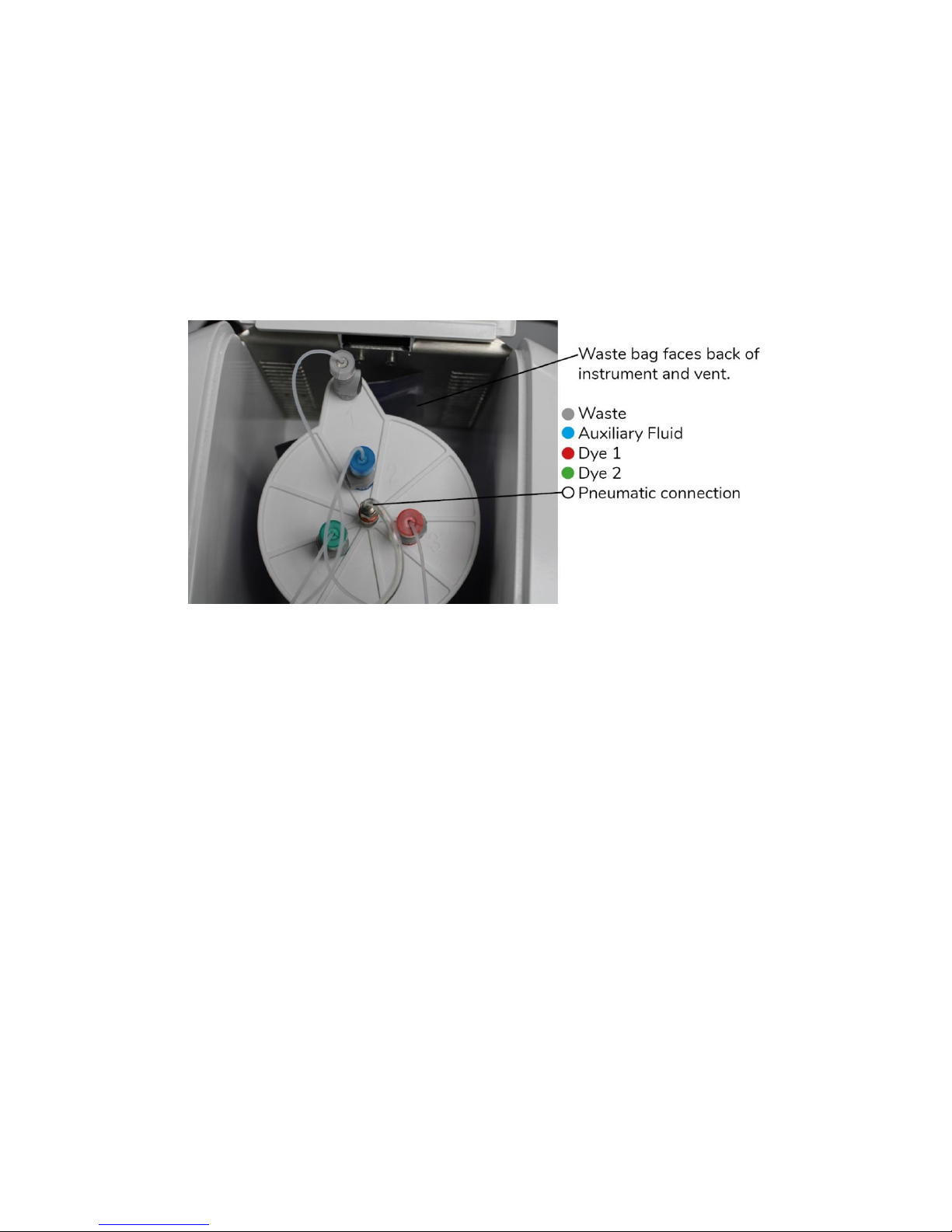
Chips are loaded by sliding them into the slot at the front of the instrument. Chips should be
inserted until a click is felt, and resistance is met. The chip should not be removed until the
run has fully completed.
Page 16
14
6.5. Replacing reagent cartridges
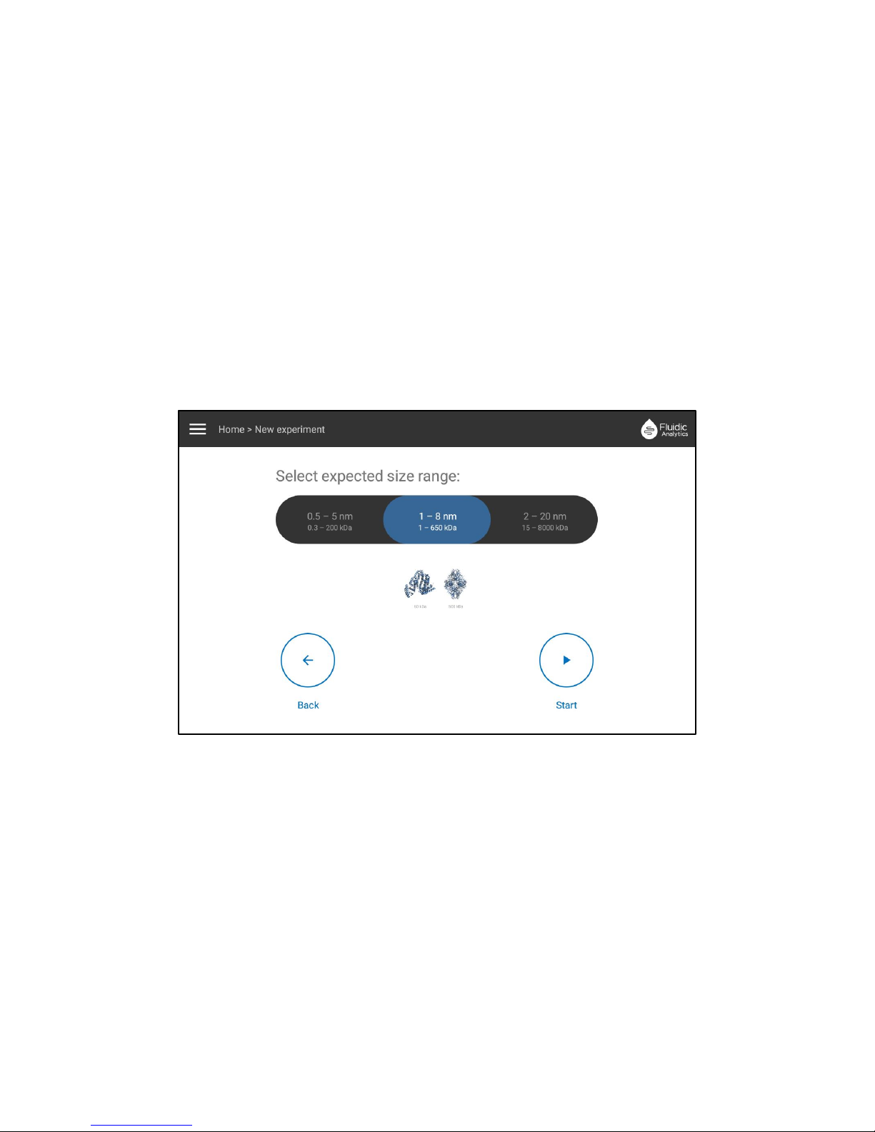
The reagent cartridge is located in a compartment at the top rear of the instrument as
shown below.
When the reagent level stated in the side bar menu is 5% or lower, or if an experiment
result gives an error code stating reagent cartridge is low, the reagent cartridge should be
replaced as per the instructions below.
This should not be done while an experiment is running.
1. Open the reagent cartridge cover by pressing down on the circular marking on the
cover.
2. Remove the 4 fluid connections (red, blue, green and grey) by pressing the button on
each connector and lifting the hoses off.
3. Remove the pneumatic connection by holding the base of the connector firmly and
lifting it off.
4. Carefully lift out and remove the old cartridge from the instrument.
5. Unpackage the new cartridge and remove the coloured blanking covers on the ports.
Place the new cartridge into the instrument ensuring it is the right way around – as
pictured above.
6. Firmly reconnect the 4 fluid connections, following the colour coding on the
connectors and the cartridge.
7. Reconnect the pneumatic line by holding the top of the connector and pressing onto
the central port, until a click is heard and the orange sleeve on the connector is
revealed. Once all connections are made, close the reagent cartridge cover again
until it clicks shut.
8. On the instrument touchscreen, open the side bar menu – you will see the low
cartridge % is still displayed.
9. Select Settings, then Machine, and touch on the blue button labelled “manually
change the cartridge ID”
Page 17
15
10. Type in the desired cartridge identifier – today’s date is recommended to record the
date of the change, but this can be any value you choose. Press “update cartridge
ID” to save.
11. The low cartridge % will still be displayed until an experiment is run or the
instrument is restarted.
Reagent cartridges are disposable and should not be re-filled.
6.6. Starting the measurement
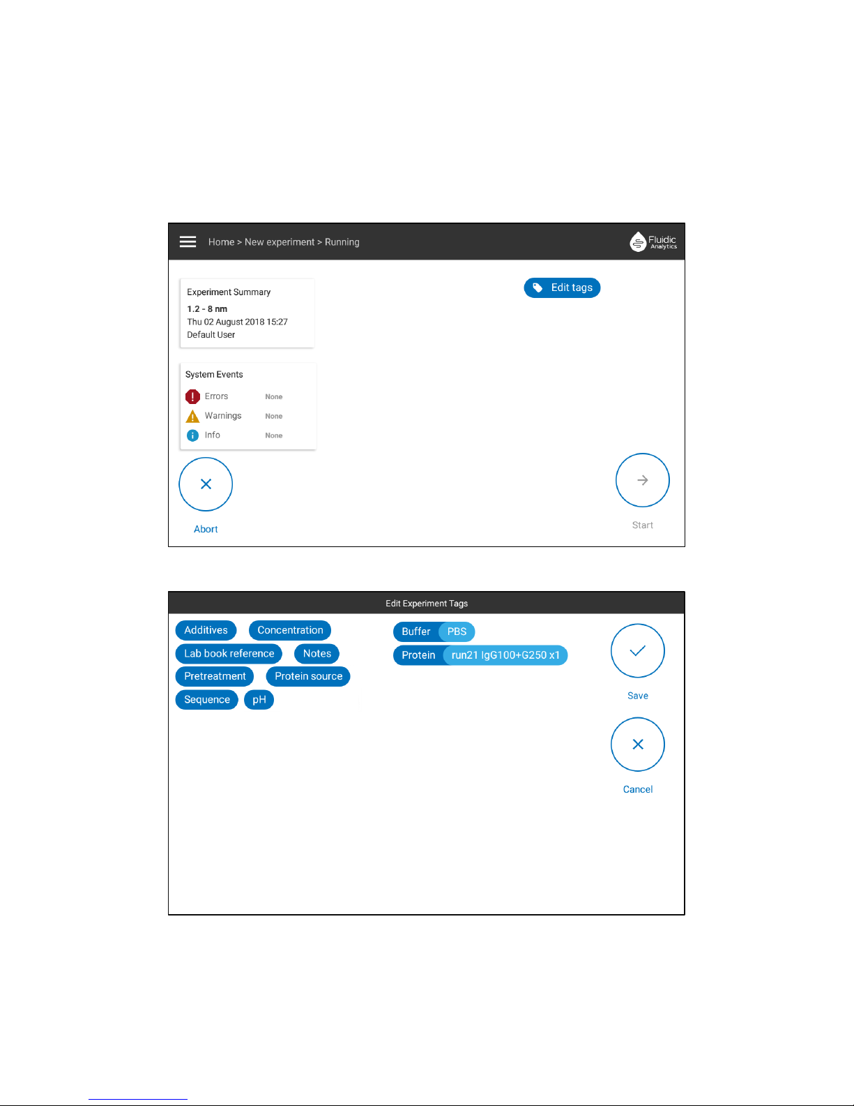
Following chip insertion, select the appropriate flow rate by choosing the expected size
range for your measurement as seen in the following screenshot.
To start the measurement, touch Start and then confirm by touching Start Experiment on
the following screen.
Do not attempt to remove the chip from the instrument while an experiment is running and
once you have pressed start.
Experiment times for each size range are approximately as follows:
• 0.5 – 5 nm – 8 minutes
• 1 – 8 nm – 10 minutes
• 2 – 20 nm – 15 minutes
Page 18
16
The measurement may then be tagged with metadata related to the experiment using the
Edit Tag button, this includes pre-prepared tags like Concentration and Buffer or you can
create your own.
Tags can be edited prior to, during, and after the run. Any tag data will be included in the
export file where results are exported.
Tag editing screen:
Page 19

17
6.7. Calibration
Calibration can be performed to improve the accuracy of concentration measurements but is
not required for most proteins and peptides, as the degree of labelling is consistent for the
majority of samples. Calibration will not affect the size measurement as the rate of diffusion,
directly measured by the instrument, has a well defined physical relationship as described
by the Stokes-Einstein equation.
For outlying proteins which are particularly lysine rich or poor, we recommend performing a
one-point calibration run using a known concentration of your protein of interest. Full details
on how to perform a calibration can be found on our website www.fluidic.com
Instrument priming
The instrument will automatically run a prime sequence to ensure that fluidic lines are fully
wetted whenever it is required. This will occur whether the instrument was turned on or off
during the idle period.
A prime sequence will run when there have been no tests run or the unit has been powered
down for 8 hours or more, or after a new cartridge has been connected.
The prime sequence will begin automatically when the first measurement run is started.
The prime takes around 10 or 20 minutes, depending on how much time has elapsed since
the last measurement run on the instrument.
The normal measurement run will begin straight after the prime sequence.
For the result given immediately after a prime, check the trace graph. If this looks normal,
the result can be used. If the trace is unusual in any way the result may have been affected
by the prime – in this instance repeat the test. See www.fluidic.com for tips on interpreting
traces.
Page 20
18
Viewing Results
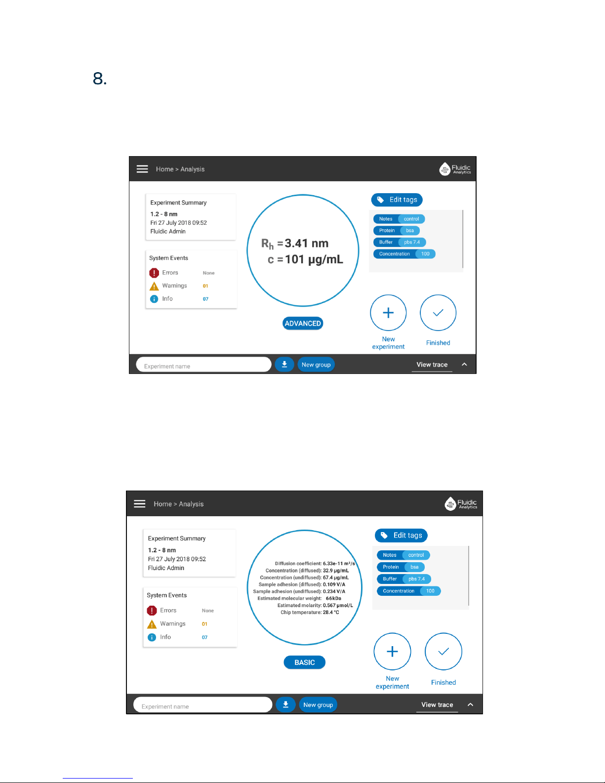
Following the measurement the results are displayed on screen.
You may begin a new experiment, finish the session and return to the home screen or
access advanced results and view the measurement trace.
Press “Finished” to return to the home screen.
Press “New experiment” to return to the size range selection and start a new measurement.
Press “Advanced” to view advanced results information including the measured chip
temperature, and the specific concentration in both the diffused and undiffused streams.
Page 21

19
Press “View trace” to see the trace plot for this measurement (see www.fluidic.com for help
with interpreting traces).
If there were any errors during the run, these will be indicated in the “System Events” box
on the left hand side. Touch on this box to expand and view more detail on the errors. See
www.fluidic.com for help with interpreting error codes.
If you return to the home screen you can access your previously generated results by
selecting the menu icon located in the top left corner of the home screen.
Touch “View results” to see a list of your previously generated results, and touch on an
individual result to open it in full results view.
Page 22

20
Shut down
Before shutting down the instrument ensure no measurements are in progress.
To shut down the Fluidity One press and hold the power button on the back of the
instrument for 5 seconds.
It is recommended to turn the instrument off overnight.
User Accounts
User accounts can help to organize your results, remember your saved settings and ensure
instrument changes are only made by approved persons.
Accounts can be created through the side bar menu – see www.fluidic.com for full details on
the different account types and how to set up and make use of user accounts.
Results storage and download
Every measurement made on the instrument is automatically saved in the internal memory.
Around 400 results can be stored. After this results should be downloaded onto a USB stick
and deleted from the instrument to make room for more.
11.1. How to download results
Download results by following these steps;
1. Insert USB stick into the port next to the touchscreen.
2. Open the side bar menu by touching the 3 stripe icon and select view results.
3. Select the result you wish to download to view it.
4. Touch the download logo at the bottom of the screen. This opens a list of file type
options – touch the desired file format for the download.
5. To download multiple results at once, it is fastest to create a group and download
the whole group (see www.fluidic.com for details on how to do this).
Results will remain saved on the instrument after they have been downloaded.
To delete results after download select view results from the side bar menu, and touch the
small graph icon next to the result, and select “Delete result” from the options.
Page 23

21
11.2. File formats available for results download
Single results or groups of results can be exported as .json .xls or .csv files.
Groups of results only can be exported as .pdf .png and .svg files – these produce a scatter
plot showing all of the results in the group.
Cleaning
Clean the outer plastic casing with mild detergent and non-abrasive cloth. Avoid organic
solvents, including ethanol and isopropanol.
Ensure no cleaning liquids get into the USB, ethernet and power supply ports or the chip
loading slot.
Service, Maintenance and Fault Repairs
The only maintenance which may be performed by instrument users is changing the
cartridge (see section 6.5).
All other maintenance, adjustments or fault repairs must be performed by Fluidic Analytics
staff or an authorized agent only.
To report a fault, request a maintenance visit, or for information on service contracts contact
us:
• Through our website; www.fluidic.com/support
• By calling +44 (0) 1223 560432 during UK business hours, or
• By emailing [email protected]
Decommissioning and storage
The instrument should be powered down, cleaned and stored in the original container.
Remove the cartridge before long term storage and store separately.
Contacting customer support
Contact the customer support team by one of these methods;
• Through our website; www.fluidic.com/support
• By calling +44 (0) 1223 560432 during UK business hours, or
• By emailing [email protected]
Page 24

22
Page 25

 Loading...