

Fluid Components Intl ST51A, ST75A, ST75AV Installation, Operation & Maintenance Instruction Manual

Doc. No. 06EN003426 Rev. C

06EN003426 Rev. C ST51A/ST75A/ST75AV Mass Flow Meters
Notice of Proprietary Rights
This document contains confidential technical data, including trade secrets and proprietary information which is the property of Fluid Components
International LLC (FCI).Disclosure of this data to you is expressly conditioned upon your assent that its use is limited to use within your company
only (and does not include manufacture or processing uses). Any other use is strictly prohibited without the prior written consent of FCI.
© Copyright 2019 by Fluid Components International LLC. All rights reserved. FCI is a registered trademark of Fluid Co mponen ts Internat iona l LLC. Info rmation subject to change w ithout not ice.
Fluid Components International LLC

ST51A/ST75A/ST75AV Flow Meter s 06EN003426 Rev. C
Table of Contents
Table of Contents ......................................................................................................................................................................................iii
List of Figures ..........................................................................................................................................................................................vii
List of Tables ........................................................................................................................................................................................... viii
1 GENERAL ......................................................................................................................................................................................... 1
Product Description ........................................................................................................................................................................... 1
Theory of Operation .......................................................................................................................................................................... 1
Safety Instructions ............................................................................................................................................................................. 1
Order Verification .............................................................................................................................................................................. 1
Hardware – Model Descriptions ................................................................................................................................................ 2
Optional Accessories ................................................................................................................................................................ 2
Specifications .................................................................................................................................................................................... 3
2 INSTALLATION ................................................................................................................................................................................. 5
Instrument Identification and Outline Dimensions ............................................................................................................................. 5
Pre-Installation .................................................................................................................................................................................. 5
Serial Number ........................................................................................................................................................................... 5
Flow Direction Alignment .......................................................................................................................................................... 5
Recommended Straight Run ..................................................................................................................................................... 7
Installing ST51A Flow Element ......................................................................................................................................................... 7
Compression Fitting Mounting .................................................................................................................................................. 7
Retractable Packing Gland Mounting ........................................................................................................................................ 9
Retraction/Removal Procedure ....................................................................................................................................... 10
Installing ST75A/ST75AV Flow Element ......................................................................................................................................... 11
Pipe Tee Installation ................................................................................................................................................................ 11
Tube Tee Installation ............................................................................................................................................................... 11
NPT Flow Tube Installation ..................................................................................................................................................... 11
Flanged Installation ................................................................................................................................................................. 11
Re-positioning the Display .............................................................................................................................................................. 11
Installing the Remote Flow Meter System ....................................................................................................................................... 12
Remote Cable ......................................................................................................................................................................... 13
Local Enclosure ....................................................................................................................................................................... 14
Remote Enclosure ................................................................................................................................................................... 15
Instrument Wiring ............................................................................................................................................................................ 17
Accessing the Interface Board Connection Terminals ............................................................................................................ 18
ESD Precautions ............................................................................................................................................................. 18
Interface Board Connections ................................................................................................................................................... 19
Power Connections ......................................................................................................................................................... 19
Signal Connections ................................................................................................................................................................. 21
4-20 mA Analog Outputs ................................................................................................................................................. 21
HART Connections .......................................................................................................................................................... 22
Fluid Components International LLC iii

06EN003426 Rev. C ST51A/ST75A/ST75AV Mass Flow Meters
Pulse Output and Alarm (Source/Sink) ........................................................................................................................... 23
Modbus Connections ....................................................................................................................................................... 24
Serial Interface Connector J9 .................................................................................................................................................. 25
3 OPERATION ................................................................................................................................................................................... 27
Overview ......................................................................................................................................................................................... 27
Instrument Configuration and Setup Using the Service Port (RS-232) ........................................................................................... 27
Main Menu .............................................................................................................................................................................. 28
Top Level Menu Commands ................................................................................................................................................... 28
Secondary Commands: CLI .................................................................................................................................................... 28
Start-up and Commissioning ........................................................................................................................................................... 28
Z Menu: Configure Flow Units and 4-20 mA Output Scaling .......................................................................................................... 29
Changing Flow Units, Example ............................................................................................................................................... 30
V Menu: Configure Outputs (4-20 mA and Source/Sink Outputs) ................................................................................................... 30
4-20 mA Configuration ............................................................................................................................................................ 32
Flow/Temperature Assignment ....................................................................................................................................... 32
NAMUR Mode ................................................................................................................................................................. 32
HART Damping Value ..................................................................................................................................................... 32
Source/Sink Output Configuration ........................................................................................................................................... 32
Source/Sink Output Functions ......................................................................................................................................... 32
Source/Sink Output Programming Parameters ............................................................................................................... 32
Serial Interface Command Reference ............................................................................................................................................. 33
Top Level Menu Commands ................................................................................................................................................... 33
CLI Commands ....................................................................................................................................................................... 34
HART Operation .............................................................................................................................................................................. 36
Process Data Operation .......................................................................................................................................................... 36
ST51A/ST75A/ST75AV HART Process Data Organization .................................................................................................... 36
ST51A/ST75A/ST75AV Process Variable Slots .............................................................................................................. 36
Primary Variable Classifications ...................................................................................................................................... 36
Device Description Files .......................................................................................................................................................... 36
EDDL Files ...................................................................................................................................................................... 37
Loading the DD Files to the 475 Field Communicator ............................................................................................................ 37
Service Data Operation ........................................................................................................................................................... 37
HART Command List Reference ..................................................................................................................................................... 40
ST51A/ST75A/ST75AV HART Universal Commands ............................................................................................................. 40
ST51A/ST75A/ST75AV HART Common Practice Commands ............................................................................................... 47
ST51A/ST75A/ST75AV HART Device Specific Commands ................................................................................................... 49
HART Command Bit Assignments .......................................................................................................................................... 52
Command Status Bytes ................................................................................................................................................... 52
Command 48, Additional Device Status Bytes ................................................................................................................ 54
HART Engineering Units Codes .............................................................................................................................................. 55
iv Fluid Components International LLC

ST51A/ST75A/ST75AV Flow Meter s 06EN003426 Rev. C
Modbus Operation ........................................................................................................................................................................... 56
Setting Up the ST51A/ST75A/ST75AV for Modbus Operation ............................................................................................... 56
ST51A/ST75A/ST75AV Modbus Commands .......................................................................................................................... 57
ST51A/ST75A/ST75AV Process Data Registers .................................................................................................................... 57
Totalizer Register Description ................................................................................................................................................. 58
ST51A/ST75A/ST75AV Modbus Service Registers ................................................................................................................ 59
Examples of Totalizer Service Register Access using ModScan32 ........................................................................................ 59
Checking the Totalizer Value .......................................................................................................................................... 59
Resetting the Totalizer Value .......................................................................................................................................... 61
Starting/Stopping the Totalizer Count ............................................................................................................................. 61
Checking K Factor Values ............................................................................................................................................... 62
Changing/Setting K Factor Values .................................................................................................................................. 62
Modbus Engineering Units Codes Table ................................................................................................................................. 64
Modbus Device Status Code Table ......................................................................................................................................... 64
4 MAINTENANCE .............................................................................................................................................................................. 65
Calibration ....................................................................................................................................................................................... 65
Electrical Connections ..................................................................................................................................................................... 65
Remote Enclosure ........................................................................................................................................................................... 65
Electrical Wiring .............................................................................................................................................................................. 65
Flow Element Connections ............................................................................................................................................................. 65
Flow Element Assembly .................................................................................................................................................................. 65
5 TROUBLESHOOTING .................................................................................................................................................................... 67
Application Verification .................................................................................................................................................................... 67
Equipment Needed ......................................................................................................................................................................... 67
Check Serial Numbers .................................................................................................................................................................... 67
Check the Instrument Installation .................................................................................................................................................... 67
Check for Moisture .......................................................................................................................................................................... 67
Check Application Design Requirements ........................................................................................................................................ 67
Verify Standard Versus Actual Process Conditions ........................................................................................................................ 67
Verifying Calibration Parameters (Diagnostics) .............................................................................................................................. 68
Hardware Verification ...................................................................................................................................................................... 69
Fuse Check ............................................................................................................................................................................. 69
Sensor Check .......................................................................................................................................................................... 69
Transmitter Circuit Calibration Check (Delta R Verification) ........................................................................................................... 70
References .............................................................................................................................................................................. 70
Equipment ............................................................................................................................................................................... 70
Procedure ................................................................................................................................................................................ 70
Fluid Components International LLC v

06EN003426 Rev. C ST51A/ST75A/ST75AV Mass Flow Meters
APPENDIX A DRAWINGS .................................................................................................................................................................. 73
APPENDIX B GLOSSARY .................................................................................................................................................................. 91
Abbreviations .................................................................................................................................................................................. 91
Definitions ....................................................................................................................................................................................... 91
APPENDIX C APPROVAL INFORMATION ........................................................................................................................................ 93
EU Information ........................................................................................................................................................................ 93
Specific Conditions of Use per FM16ATEX0008X .................................................................................................................. 94
IEC Information ....................................................................................................................................................................... 95
APPENDIX D CUSTOMER SERVIC E .............................................................................................................................................. 101
Customer Service/Technical Support .................................................................................................................................... 101
Warranty Repairs or Returns ................................................................................................................................................ 101
Non-Warranty Repairs or Returns ......................................................................................................................................... 101
Extended Warranty ............................................................................................................................................................... 101
Return to Stock Equipment ................................................................................................................................................... 101
Field Service Procedures ...................................................................................................................................................... 102
Field Service Rates ............................................................................................................................................................... 102
vi Fluid Components International LLC

ST51A/ST75A/ST75AV Flow Meter s 06EN003426 Rev. C
List of Figures
Figure 1 – Probe Serial Number, Reference Flat and Flow Direction Mark .............................................................................................. 5
Figure 2 – Serial Number Location on Interface Board (AC Version Shown) with Blind Cover Removed ................................................ 6
Figure 3 – ST51A Flow Arrow Alignment .................................................................................................................................................. 6
Figure 4 – Recommended Straight Run (ST75A Shown) ......................................................................................................................... 7
Figure 5 – Flow Element Installation, Compression Fitting ST51A ........................................................................................................... 8
Figure 6 – Flow Element Installation, Retractable Packing Gland ST51A ................................................................................................ 9
Figure 7 – Retractable Packing Gland Locking Collar Detail .................................................................................................................. 10
Figure 8 – Display Re-positioning ........................................................................................................................................................... 12
Figure 9 – Typical Remote Flow Meter System (ST51A with ½" NPT Cable Port Shown) ..................................................................... 12
Figure 10 – Remote Cable, Interconnecting ........................................................................................................................................... 13
Figure 11 – Remote Cable Installation, Local Enclosure ........................................................................................................................ 14
Figure 12 – Local Enclosure Remote Cable Wiring ................................................................................................................................ 14
Figure 13 – Remote Cable/Bracket Installation, Remote Enclosure ....................................................................................................... 16
Figure 14 – Remote Enclosure Interface Board Connector J4 Detail (AC Version Shown).................................................................... 16
Figure 15 – ST51A/ST75A/ST75AV Wiring Access ................................................................................................................................ 17
Figure 16 – Recommended Wire Routing/Internal Ground Screw .......................................................................................................... 18
Figure 17 – Power and Signal Wiring Terminals ..................................................................................................................................... 19
Figure 18 – Input Power Fuse Locations ................................................................................................................................................ 20
Figure 19 – Single Connection and Multidrop HART Setups .................................................................................................................. 22
Figure 20 – Sink Output .......................................................................................................................................................................... 23
Figure 21 – Source Output ...................................................................................................................................................................... 23
Figure 22 – Modbus Wiring ..................................................................................................................................................................... 24
Figure 23 – Serial Cable Adapter 025859-01 Plugged Into Flow Meter J9 Header ................................................................................ 25
Figure 24 – Block Diagram: Flow Meter Serial Port Connections, FC88 and Computer ........................................................................ 26
Figure 25 – Z Menu Command Structure: Units and Scaling Setup ....................................................................................................... 29
Figure 26 – V Menu Command Structure: Output Configuration Setup .................................................................................................. 31
Figure 27 – Field Communicator Easy Upgrade Utility, Import DD ......................................................................................................... 37
Figure 28 – Reference and Active Sensor Resistance Check (AC Version Shown) .............................................................................. 69
Figure 29 – Transmitter Circuit Calibration Diagram ............................................................................................................................... 71
Figure 30 – Basic Instrument Assembly: ST51A, ST75A and ST75AV .................................................................................................. 74
Fluid Components International LLC vii

06EN003426 Rev. C ST51A/ST75A/ST75AV Mass Flow Meters
List of Tables
Table 1 – Optional Accessories ................................................................................................................................................................ 2
Table 2 – Compression Fitting Material .................................................................................................................................................... 8
Table 3 – Power and Signal Wiring Summary ........................................................................................................................................ 21
Table 4 – Serial Port J9 Pinout ............................................................................................................................................................... 25
Table 5 – Serial (COM) Port Configuration ............................................................................................................................................. 27
Table 6 – Typical Serial Interface Top Level Commands for Flow Meter Configuration ......................................................................... 29
Table 7 – Flow Unit Example .................................................................................................................................................................. 30
Table 8 – Top Level Menu Commands ................................................................................................................................................... 33
Table 9 – List of CLI Commands ............................................................................................................................................................ 34
Table 10 – ST51A/ST75A/ST75AV HART Process Variables ................................................................................................................ 36
Table 11 – ST51A/ST75A/ST75AV HART Device Registration Information ........................................................................................... 37
Table 12 – HART Universal Commands ................................................................................................................................................. 40
Table 13 – HART Common Practice Commands ................................................................................................................................... 47
Table 14 – HART Device Specific Commands ....................................................................................................................................... 49
Table 15 – Command Status Bytes, Bit Assignments ............................................................................................................................ 53
Table 16 – Command-Specific Response Codes ................................................................................................................................... 53
Table 17 – Command 48, Additional Device Status Bytes Bit Assignments ........................................................................................... 54
Table 18 – HART Engineering Units Codes ........................................................................................................................................... 55
Table 19 – ST51A/ST75A/ST75AV Modbus Function Codes ................................................................................................................. 57
Table 20 – ST51A/ST75A/ST75AV Modbus Process Data .................................................................................................................... 58
Table 21 –Modbus Service Data ............................................................................................................................................................. 59
Table 22 – Modbus Engineering Units Codes ........................................................................................................................................ 64
Table 23 – Device Status Code Bit Assignments, Register #4025 ......................................................................................................... 64
Table 24 – Diagnostic Test Sequence .................................................................................................................................................... 68
Table 25 – Appendix A, List of Drawings ................................................................................................................................................ 73
viii Fluid Components International LLC

ST51A/ST75A/ST75AV Mass Flow Meters GENERAL
Warning:
Explosion Hazard. Do not disconnect equipment when flammable or combustible atmosphere is present.
1 GENERAL
Product Description
The ST51A and ST75A/ST75AV Series are thermal dispersion, industrial process grade air/gas flow meters. They are suitable for all air
and gas flow measurement applications. The ST51A is an insertion type flow meter for line sizes ranging from 2″ to 24″ [51 to 610 mm].
The ST75A is an in-line type flow meter for line sizes ranging from ¼″ to 2″ [6 mm to 51 mm]. Both ST51A and ST75A/ST75AV flow meters
provide direct mass flow measuring and measures flow rate, totalized flow and temperature.
The measurements are made available to the user through dual 4-20 mA analog output channels, a separate source and sink channel (pulse
output for totalizer or level output for alarm) and HART. The optional alphanumeric LCD display provides real-time process variable values, flow
range and process description information. There are no moving parts to clean or maintain. These flow meters are offered in a wide selection of
process connections to fit with any process piping and versions are available for temperature service from -0 °F [-18 °C] to 350 °F [177 °C].
ST51A and ST75A/ST75AV’s electronics/transmitter can be integrally mounted with the flow sensor or remote mounted up to 100′ [30 m]
from the sensor element. All ST51A and ST75A/ST75AV flow meters are precision calibrated in FCI’s world-class, NIST traceable
calibration facility on one of our flow stands matched to the customer’s gas application and actual installation conditions.
Theory of Operation
The instrument is functionally based on the thermal dispersion operating principal. A low powered heater produces a temperature
differential (ΔT) between two Resistance Temperature Detectors (RTDs) by heating one of the RTDs above process temperature. As the
process mass flow rate increases, the temperature differential (ΔT) between the RTDs decreases. The ΔT between the RTDs is
proportional to the process mass flow. The flow transmitter converts the RTD’s ΔT signal into a scaled flow output signal. The signal from
the unheated RTD is used to provide the process temperature value.
Safety Instructions
● Field wiring shall be in accordance with NEC (ANSI-NFPA 70) for Division 2 hazardous locations and CEC (CSA C22.1) for division 2
locations as applicable.
● The instrument must be installed, commissioned and maintained by qualified personnel trained in process automation and control
instrumentation. The installation personnel must ensure the instrument has been wired correctly according to the applicable wiring diagram.
● All location specific installation and wiring requirements (i.e., local electrical codes) must be met and maintained. Install an input
power circuit breaker or power disconnect switch and fuse near the flow meter to interrupt power during installation and maintenance.
A switch or circuit breaker is required if installation is in a hazardous area.
● The flow meter contains electrostatic discharge (ESD) sensitive devices. Use standard ESD precautions when handling the circuit
board assemblies.
● Hazardous Areas: The instrument is designed for use in hazardous areas. The approved area classification is identified on the
nameplate along with the temperature and pressure limitations. See Agency Approvals, page 3 and APPENDIX C, page 93 for a
complete listing of the instrument’s safety/hazardous areas approvals.
Order Verification
● Verify the received hardware matches the purchased hardware and application requirements. Verify the model number and part
number on the instrument I.D. tag matches the purchased model number part number.
● Review the calibration requirements as specified on the Engineering Data Sheet in the documentation package. Verify the flow,
temperature and pressure limits meet the application requirements.
Fluid Components International LLC 1

GENERAL ST51A/ST75A/ST75AV Mass Flow Meters
Part Number
Description
FC88
014108-03
Hardware – Model Descriptions
ST51A – Single point insertion element with flow and temperature process output
ST75A – In-line element with flow and temperature process output
ST75AV – Vortab In-line element with flow and temperature process output
Optional Accessories
Table 1 – Optional Accessories
Portable Hand-held Communicator
PC Interface Communications Kit, for RS-232 serial port connection
2 Fluid Components International LLC

ST51A/ST75A/ST75AV Mass Flow Meters GENERAL
NPT Line
Size
Min SCFM
0.04
0.13
0.22
0.35
0.85
1.40
Min [NCMH]
[0.07]
[0.22]
[0.38]
[0.59]
[1.44]
[2.38]
Max SCFM
17.34
50.64
88.88
139.95
539.31
559.27
Max [NCMH]
[29.47]
[86.04]
[151.00]
[237.78]
[576.48]
[950.20]
Tubing Line Size
¼"
½"
1"
Min SCFM
0.01
0.05
0.25
Min [NCMH]
[0.01]
[0.09]
[0.42]
Max SCFM
3.02
21.15
99.08
Max NCMH
[5.14]
[35.94]
[168.33]
Specifications
Instrument
■ Media Compatibility
ST51A: Air, compressed air, nitrogen, biogas, digester gas,
methane, natural gas
ST75A/ST75AV: Air, compressed air, nitrogen, oxygen, argon,
CO2, other inert gases, natural gas and other gases as identified
in the Order Information Sheet (OIS)
■ Pipe/Line Size Compatibility
ST51A: 2″ to 24″ [51 mm to 610 mm]
ST75A/ST75AV: ¼″ to 2″ [6 mm to 51 mm]
■ ST51A Flow Range
0.3 SFPS to 400 SFPS [0.08 MPS to 122 MPS]
■ ST75A/ST75AV Flow Range*
¼" ½" ¾" 1" 1 ½" 2"
Directive 2014/30/EU Electromagnetic Compatibility EMC
Directive 2014/35/EU Low Voltage
Directive 2011/65/EU RoHS 2
FM, FMc
Explosion-proof: Class I, Div. 1, Groups B, C, D
Dust-ignitionproof: Class I I/II I, Div. 1, G roups E, F, G; Type 4X; IP66
Nonincendive: Class I, Div. 2, Groups A, B, C, D
SIL 1 compliant; Safe Failure Fraction (SFF) 78.5% to 81.1%
CRN No.: 0F0303
Contact FCI for other approvals and conditions of use.
■ Warranty
2 years
Flow Element
■ Type
Thermal dispersion
■ Material of Construction
ST51A: 316L stainless steel body with Hastelloy-C22 thermowells; 316
stainless steel compression fitting with Teflon or stainless steel ferrule.
ST75A/ST75AV: All -welded 316 stainless steel probe element with
Hastelloy-C22 thermowells; 316 stainless steel NPT, flange and
tube fittings.
* Range subject to gas type and conditions
■ Accuracy
ST51A/ST75A: Standard: ±2% reading ±0.5% full scale
Optional: ±1% reading ±0.5% full scale
ST75AV: ±1% reading ±0.5% full scale
■ Repeatability
±0.5% of reading
■ Temperature Compensation
Standard: 40 to 100 °F [4 to 38 °C]
Optional: 0 to 250 °F [-18 to 121 °C]
■ Turndown Ratio
3:1 to 100:1
■ Agency Approvals
CE Mark
Directive 2014/34/EU ATEX
IECEx Scheme
ATEX/IECEx: II 2 G Ex db IIC T6...T1 Gb
II 2 D Ex tb IIIC T85°C...T300°C Db; IP66/IP67
Ta = -40°C to +65°C
FM, FMc: Class I, Div 1, Groups B, C, D
Class I, Div 2, Groups A, B, C, D
Class II/III Div 1, Groups E, F, G
Type 4X, IP66
■ Process Connection
ST51A: ½″ Male NPT or ¾″ Male NPT compression fitting with
stainless steel or Teflon ferrule
Insertion Length:
1″ to 6″ [25 mm to 152 mm]
1″ to 12″ [25 mm to 305 mm]
1″ to 18″ [25 mm to 457 mm]
ST75A: T-fitting [Female NPT]: ¼″, ½″, ¾″, 1″, 1-½″ or 2″
Tubing: ¼″, ½″, 1″
ST75AV: Female NPT, Male NPT
Flange: ¼″, ½″, ¾″, 1″, 1-½″ or 2″
■ Maximum Operating Pressure
ST51A stainless steel ferrule: 500 PSIG [34 bar(g)]
Teflon ferrule: 150 PSIG [10 bar(g)]
ST75A: T-fitting [Female NPT]: 240 PSIG [16.5 bar(g)]
Tube: 600 PSIG [41 bar(g)]
ST75AV: 600 PSIG [41 bar(g)]
■ Flow Element Temp Range
ST51A
stainless s
teel ferrule: 0 °F to 350 °F [-18 °C to 177 °C]
ST75A: 0 °F to 250 °F [-18 °C to 121 °C]
Teflon ferrule: 0 °F to 200 °F [-18 °C to 93 °C]
Fluid Components International LLC 3

GENERAL ST51A/ST75A/ST75AV Mass Flow Meters
Part No.
Type
Amp
Code
Ampere
Rating
Max. Voltage
Rating
Littelfuse Series
454: 045401.5
Slo-Blo
01.5
1.50 A
125 V
Flow Transmitter
■ Enclosure
Rating: NEMA 4X [IP67]
Material: Standard – Aluminum, polyester powder-coated
Optional – 316 stainless steel
Cable/Wiring port: Dual ½" female NPT or M20x1.5
■ Operating Temperature
0 °F to 140 °F [-18 °C to 60 °C]
■ Maximum Relative Humidity
100%
■ Maximum Altitude
12,000 feet (3,658 meters)
■ Input Power
DC: 18 VDC to 36 VDC
AC: 90 VAC to 264 VAC (4.5 Watts max.; CE Mark voltage 100
VAC to 240 VAC)
Instrument (Element + Sensor): 4.5 Watts
Sensor only: 0.30 Watts
■ Analog Output Signals
Two 4-20 mA outputs configured for flow rate or temperature.
Typical load: 250 Ω; Max load: 500 Ω. Both outputs have fault
indication per NAMUR NE43 guidelines, user selectable for high
(> 21.0 mA) or low (< 3.6 mA).
■ Installation and Mounting
ST51A – Integral with sensor element or remote mountable with
interconnecting cable length of: 10′ [3 m), 25′ [7,6 m], 50′ [15 m],
100' [30 m] or custom length.
ST75A/ST75AV – In-line “T”, NPT or tube. Available in remote
mountable configuration with interconnecting cable length of: 10′
[3 m], 25′ [7,6 m], 50′ [15 m], 100' [30 m] or custom length.
■ Source/Sink Outputs
One source output and one sink output provides totalized flow
(pulse signal) or alarm setpoint (level signal). Pulse width at 50%
duty cycle. 1-500 Hz pulse output for total flow.
• Source: 22 ±2 VDC, 25 mA
• Sink: External (user) power source and load not to exceed 40
VDC and 150 mA
■ Communication Port
• RS-232C, standard
• Modbus, standard
• HART, standard
1
■ Digital Display
Two-line x 16 character LCD; displays measured value and
engineering units. Top line assigned to flow rate, second line user
assignable to temperature reading, flow totalizer or alternating. Display
can be rotated in 90° increments for optimum viewing orientation.
1
Display “delete” option (Blind, no display window) also available.
■ Input Power Fuse
Refer to Power Fuse Replacement on page 20 for fuse
replacement instructions.
4 Fluid Components International LLC
ST51A/ST75A/ST75AV Mass Flow Meters INSTALLATION
Warning:
The ambient temperature range and applicable temperature class of the ST51A and ST75A/ST75AV Series flow
C01157-1-1
SERIAL NUMBER
ORIENTATION
ST51 EXTENSION PIPE
ST75/ST75V HEX
FLOW DIRECTION
MARK
FLOW DIRECTION
MARK
SERIAL NUMBER
ORIENTATION
2 INSTALLATION
meters are based on the maximum process temperature for the particular application as follows; T6 for -40 °C ≤ Ta ≤
+55 °C; T3 for -40 °C ≤ Ta ≤ +65 °C.
Instrument Identification and Outline Dimensions
Appendix A provides outline dimensions and mounting bracket dimensions for all integral and remote mounted electronic configurations.
Verify all dimensions meet the application requirements before beginning installation.
Pre-Installation
Serial Number
The ST51A, ST75A and ST75AV (Vortab) flow meters can be specified with integral or remote electronics. The flow element has a serial
number etched into the side of the extension pipe (ST51A) or HEX (ST75A/ST75AV) as shown in Figure 1 below. The tag on the enclosure
includes serial number and model number. A serial number is written on the transmitter’s PWB silkscreen (both AC and DC input) as
shown in Figure 2. The flow sensor and transmitter circuit are calibrated as a matched set. Always pair these components together unless
an exception is made by an FCI technician.
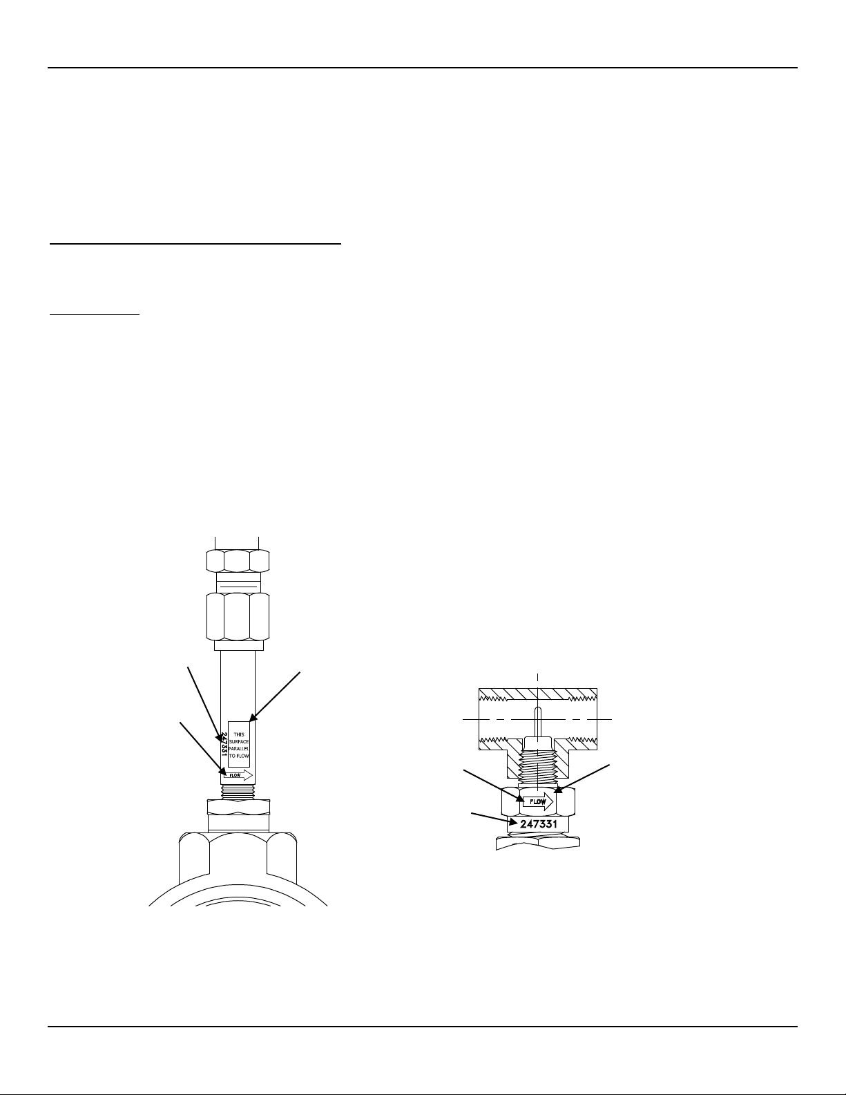
Flow Direction Alignment
All sensor elements have a flow arrow indicator marked on the element assembly at the reference flat, which indicates the flow direction for
which the flow element has been calibrated. Install the instrument with the flow arrow facing in the same direction as flow in the pipe
stream as shown in Figure 3 and Figure 4. The ST75A/ST75AV flow element has been calibrated directly in the pipe tee or tube tee for
orientation and insertion depth, as shown on Figure 4. See APPENDIX A, page 73 for orientation details.
REFERENCE FLAT
Figure 1 – Probe Serial Number, Reference Flat and Flow Direction Mark
Fluid Components International LLC 5
REFERENCE HEX FLAT

INSTALLATION ST51A/ST75A/ST75AV Mass Flow Meters
C01158-1-2
90°
C01159-1-1
SERIAL NUMBER
FLOW DIRECTION MARK
POINTS TO FLOW DIRECTION
REFERENCE/O RIE NT ATI ON FLAT
THERMOWELLS PERPENDICULAR
BLOCK
Figure 2 – Serial Number Location on Interface Board (AC Version Shown) with Blind Cover Removed
6 Fluid Components International LLC
TO FLOW DIRECTION
Figure 3 – ST51A Flow Arrow Alignment
PARALLEL TO FLOW DIRECTION

ST51A/ST75A/ST75AV Mass Flow Meters INSTALLATION
Caution:
Elements are shipped in a protective sleeve. After removing the sleeve, keep the element from sliding through the
C00568-3-1
* AT LEAST 20 DIAMETERS
10 DIAMETERS
DIAMETER
* OPTIMUM CONDITION
FLOW
Recommended Straight Run
For optimal flow meter performance FCI recommends a minimum of 20 pipe diameters upstream straight run and 10 pipe diameters of
downstream straight run. See Figure 4 below. Where straight run is limited, FCI offers Vortab flow conditioners for use in applications that
have significant straight run limitations. FCI uses the AVAL application modeling software to predict meter performance in each installation.
AVAL outputs are available to review prior to order placement and will indicate performance expectations both with and without flow
conditioning.
Installing ST51A Flow Element
Compression Fitting Mounting
The ST51A is available with both Teflon compression fitting ferrules and metal ferrules. While the Teflon ferrule can be readjusted, it has a
lower process pressure rating and over-tightening may cause it to become stuck or damage the extension pipe. The metal ferrule version
can only be tightened down once and becomes permanently positioned. The ferrule type is indicated in the instrument part number
displayed on the instrument tag. This can be cross-referenced with the Ordering Information Sheet (OIS).
All flow meters have been calibrated with the flow element located at the centerline of the pipe and flow stream as shown in Figure 5.
Couplings and threadolets come in various dimensions. Proper installation requires that the element be measured with consideration to
process connection dimensions and pipe centerline. Install the element in the line with the compression fitting lightly tightened around the
extension, then slowly move the pipe extension forward until the element is at centerline as shown.
compression fitting and contacting the opposing wall with any force. Hitting the pipe wall may damage the element
and upset the calibration (critical in top mount installations).
See APPENDIX A for instrument outline dimensional details.
AFTER LAST FLO W DISTURBANCE
BEFORE NEXT
FLOW DISTURB ANCE
Figure 4 – Recommended Straight Run (ST75A Shown)
Fluid Components International LLC 7

INSTALLATION ST51A/ST75A/ST75AV Mass Flow Meters
Ferrule
Torque
Teflon
65 in - lbs
316 SST
65 ft - lbs
Note:
XXXX
FLUID COMPONENTS
INTERN A TIONAL LLC
y
C00584-1-3
MOUNTING ORIEN TATION OF FLATS
TO BE PARALLEL TO FLOW
2X 1/2" NPT,
OPTIONAL M20 x 1.5
ADJUSTABLE COMPRES SION FITTING,
OPTIONA L TEFLON OR METAL FERRULE
ENCLOSURE MEETS EXPLOSION PROOF
WATER AND DUST TIGHT APPROVALS
OPTIONAL DUAL LINE DIGITAL DISPLAY,
90° INCREMENTAL ROTATION
1/2 OR 3/4 INCH NPT
PROCESS CONNECTION
FLOWARROW
LASER ETCHED INSERTION SCALE
SERIAL NUMBER
REDUCER
BUSHING
PROTEC TIVE SHROUD
OVER PROBE TIPS
0.56
[014]
4.00
[102]
U LENGTH
VARIABLE
4.5
[114]
3.28
[83]
3.56
[90]
L
C
Figure 5 – Flow Element Installation, Compression Fitting ST51A
The flow element is properly mounted when the tip of the flow element is located 0.50 inches (13 mm) past the pipe centerline. The scale
etched on the side of the insertion pipe indicates the length to the tip of the flow element. Follow the steps below to install the ST51A flow
element.
1. Calculate the insertion depth using the equation below.
I = Insertion depth
I.D. = Pipe inside diameter
T = Pipe wall thickness
C = Pipe mounting coupling and compression fitting (installed length)
..
= 0.50" +
I = __________
2. Mark the insertion pipe at the calculated insertion depth.
3. Apply proper thread sealant to the tapered pipe thread on the compression fitting and secure into pipe mounting coupling.
4. Insert the flow element to the insertion depth mark making sure the orientation flat is aligned parallel to the flow direction. Hand tighten
the compression nut. Compression fitting manufacturer recommends 1-1/4 turns past hand tight.
5. Tighten the compression nut to the torque specified for the corresponding ferrule material as shown in Table 2 below.
+ +
Table 2 – Compression Fitting Material
8 Fluid Components International LLC
The metal ferrule configuration can only be tightened one time. Once tightened, the insertion length is no longer
adjustable.

ST51A/ST75A/ST75AV Mass Flow Meters INSTALLATION
Caution:
For applications where the process media is pressurized to greater than 232 psig [16 bar(g)] make sure to first
C01444-1-1
C
L
LOCKING COLLAR
PACKING NUT
MARK
INSERTION
DEPTH
OPTIONAL BALL VALVE:
CUSTOMER-SUPPLIED OR
PURCHASED FROM FCI
Retractable Packing Gland Mounting
A retractable packing gland, with ½" MNPT or ¾" MNPT threads and graphite or Teflon packing, is a process connection option. FCI single
point flow meters are calibrated at the centerline of the process pipe. The flow element is properly mounted when the tip of the flow
element is located .50 inches (13 mm) past the pipe centerline. Follow the below steps to install/retract instruments with the retractable
packing gland option.
1. The scale etched on the side of the insertion probe indicates the length to the tip of the flow element. Calculate the Insertion depth
using the equation and Figure 6 below.
I = Insertion depth
I.D. = Pipe inside diameter
T = Pipe wall thickness
C = Pipe mounting coupling and compression fitting (installed length)
..
= 0.50" +
I = __________
+ +
Figure 6 – Flow Element Installation, Retractable Packing Gland ST51A
2. Mark the insertion pipe at the calculated insertion depth.
3. Ball Valve Applications Only: If a ball valve is required, install the ball valve to the process mounting coupling. Close the ball valve
to prevent the process media from leaking out when installing the packing gland with the process line pressurized.
4. Apply the proper thread sealant compatible with the process media to the male threads of the packing gland. Fully retract the insertion
probe into the cavity of the packing gland and install the packing gland into the process mounting coupling or ball valve. If a ball valve
is not used, make sure to first depressurize the process line before installing.
5. Tighten the packing nut until the internal packing is tight enough to prevent excess process leakage, but also allow the insertion probe
to be inserted into place. For ball valve applications, open the ball valve after the packing nut has been tightened.
depressurize the process line before making the insertion.
6. Align the orientation flat and flow arrow parallel to the flow direction and proceed to insert the flow element into the process media
pipe up to the insertion depth mark.
7. Tighten the packing nut another ½ to 1 turn tight (approximately 20 ft-lbs) until the packing has created a full seal.
8. Ensure the locking collar is properly secured to the back of the packing gland. Torque the two No. 8-32 socket head cap screws on
the locking collar to 20 in-lbs using a 9/64" hex key.
Fluid Components International LLC 9

INSTALLATION ST51A/ST75A/ST75AV Mass Flow Meters
Caution:
For applications where the process media is pressurized to greater than 232 psig [16 bar(g)] make sure to first
PACKING NUT
LOOSEN THIS SCREW
LOCKING COLLAR
C01445-1-1
Retraction/Removal Procedure
1. Loosen the socket head cap screw on the side of the locking collar. See Figure 7 below.
depressurize the process line before retracting the flow element. At 232 psig [16 bar(g)], the effective force on the
insertion probe is 45.5 lbs (20.6 kg), which is the limit at which the flow element can be safely guided by hand. When
using hands to restrain the retraction, be prepared for a rapid pressure impulse of the flow element. Make sure that
there are no objects directly behind the flow element as the insertion probe may retract very quickly.
Figure 7 – Retractable Packing Gland Locking Collar Detail
2. Slowly loosen the packing nut until the insertion probe begins to retract. Use hands as needed to help control the retraction. If the
probe does not begin to retract itself, gently shake and pull the insertion probe until the flow element has been fully retracted into the
packing gland.
3. For ball valve applications, close the ball valve immediately after retraction to seal off the process. After closing the ball valve it is then
safe to remove the flow element from the back end of the ball valve. If a ball valve is not being used, make sure to first
depressurize the process line before removing the flow element.
10 Fluid Components International LLC

ST51A/ST75A/ST75AV Mass Flow Meters INSTALLATION
Caution:
The element is shipped already installed in the tee oriented for inline installation. Do not remove the sensing element
Caution:
The instrument contains electrostatic discharge (ESD) sensitive devices. Use standard ESD precautions when
Warning:
To avoid damage to board components use fingers only to remove the board. Do not pry the board off using a
Installing ST75A/ST75AV Flow Element
from the tee during installation as performance can be affected.
The ST75A/ST75AV is available in pipe tee configurations with NPT threads and tubing tees with a compression fitting to clamp down on
concentric smooth surface tubing. The pipe tee versions are standard 150# class rated tees suitable for service up to 150 PSIG at the
process temperature maximum of 250 °F (121 °C). The compression fitting material offered in the tube type configuration is rated for 250
PSIG service. See APPENDIX A for instrument outline dimensional details.
Pipe Tee Installation
With pipe extensions cut to length and sealing materials used on the threads, install flow element section by slowly rotating the
configuration until secure. Complete by installing the opposing end pipe section using care to secure the element assembly either in a top
mount or side mount position.
Tube Tee Installation
Clean all mating surfaces of the tee fitting, ferrules and the flow tube. Insert the flow tubing into the tee fitting. Make sure the tubing rests
firmly in the fitting counter bore seat. Tighten the nut on both ends of the tee by hand. Hold the fitting body steady with a backup wrench
and tighten the fitting nuts 1-1/4 turns from hand-tight baseline.
The ST75AV is available with flow tube configurations offering male and female NPT threads, ANSI flanges and DIN flanges. The flow tube
assemblies are rated for service up to 240 PSIG at the process temperature maximum of 250 °F (121 °C).
NPT Flow Tube Installation
With pipe extensions properly cut to length and sealing materials used on the threads, install flow element section by slowly rotating the
configuration until firmly secure on the pipe section. Complete by installing opposing end pipe section, using care to firmly secure the
element assembly either in a top mount or side mount position.
Flanged Installation
Clean all mating surfaces. Install appropriate sealing gasket between mating flanges. Tighten flange mating hardware to meet system
sealing requirements.
Re-positioning the Display
The LCD digital display can be rotated in 90° increments to improve its readability if necessary for the application. Referring to Figure 8
below, follow these steps to re-position the display.
1. Use .050″ hex key to loosen set screw locking window lid and then unscrew window lid from enclosure body.
2. Lift and remove blue bezel.
3. Unplug transmitter/display board from power supply board by pulling display board straight up. Carefully set board aside.
4. Removing transmitter/display board exposes power supply board in enclosure body. Remove two securing 6-32 x ¼″ Phillips pan
head screws and star washers from power supply board.
5. Turn power supply board in 90° steps in either direction until desired orientation is achieved.
6. Secure power supply board to enclosure body using hardware removed in step 4. Use alternate pair of mounting holes in power
supply board if required for new display orientation.
7. With transmitter/display board aligned over power supply board (connectors mate only one way) press down to fully engage
connectors on both boards.
8. Reinstall bezel over transmitter/display board by engaging bezel guide posts into corresponding holes in display board.
9. Reinstall window lid. Tighten lid one full turn past point where O-ring makes contact with lid, then tighten lid set screw to lock lid (set
screw must not protrude from its threaded hole after tightening).
handling the instrument.
screwdriver or similar tool.
Fluid Components International LLC 11

INSTALLATION ST51A/ST75A/ST75AV Mass Flow Meters
C01314-1-1
U LENG TH
DIMENSION
BEZEL
TRANSMITTER/
DISPLAY BOARD
GUIDE POST
HOLES
POWER SUPPLY BOARD
BEZEL GUIDE PO ST (2 PLACES)
WINDOW LID
2X ½" NPT PORT
LOCAL
(BLIND)
REMOTE
ELECTRONICS
BRACKET
ASSEMBLY
REMOTE CABLE
(NPT CONFIGURATI O N SHOW N)
PROBE
PIPE
(TURN THIS BOARD 90°
INCREMENTS TO POSITION DISPLAY)
Installing the Remote Flow Meter System
Remote transmitter instruments include the following components: local enclosure containing the flow element sensor, remote enclosure
containing the display/electronics and interconnecting remote cable. Both enclosures are explosion-proof ATEX/IECEx rated. A typical
remote flow meter system is shown in Figure 9 below.
ENCLOSURE
Figure 8 – Display Re-positioning
ENCLOSURE,
ASSEMBLY
12 Fluid Components International LLC
Figure 9 – Typical Remote Flow Meter System (ST51A with ½" NPT Cable Port Shown)

ST51A/ST75A/ST75AV Mass Flow Meters INSTALLATION
Remote Cable
The remote cable connects the local enclosure’s flow element sensor to the transmitter electronics in the remote enclosure. The cable is
available in standard lengths (10/25/50/100 ft. [3/7.6/15/30 m]) as well as custom length as specified in the order information sheet (OIS).
The customer is to supply the appropriate NPT or metric cable fittings for the remote cable. The cable end terminated in a 2x4 female
socket plug connects to the 2x4 pin connector on the interface board inside the remote enclosure. The cable end with 6 metal ferrules
connects to Phoenix connector TB1 on the interconnection board inside the local enclosure. Figure 10 below shows the remote cable
assemblies with customer-supplied pieces.
Figure 10 – Remote Cable, Interconnecting
Fluid Components International LLC 13

INSTALLATION ST51A/ST75A/ST75AV Mass Flow Meters
EXT. GROUND SCREW,
HEX WASHER
LOCAL
ENCLOSURE
(BLIND LID
REMOVED)
REMOTE CABLE
C01317-1-1
6-POS. PHOENIX
CONN. TB1
Remote Cable Connnections to TB1
2X 6-32 x ½" PAN HD.
PHILLIPS SCREW/
#6 STAR WASHER
INTER-
CONNECTION
BOARD
TIE-WRAP
GROMMET
TB1 Pin No. Wire Color Label
1 Orange ACT_EXC+
Black ACT_SEN+
Green ACT_EXC-
Red REF_EXC+
Brown REF_SEN+
Yellow REF_EXC-
2
3
4
5
6
Local Enclosure
Install the local enclosure as described in Installing ST51A Flow Element and Installing ST75A/ST75AV Flow Element above. Depending
on the configuration as specified by the order information sheet the ST51A local enclosure is supplied with a ½" or ¾” process connection,
and the ST75A/ST75AV is supplied with a male NPT, female NPT or flanged process connection.
Figure 11 below shows the local enclosure remote cable installation.
14 Fluid Components International LLC
Figure 11 – Remote Cable Installation, Local Enclosure
Figure 12 below shows the remote cable wiring inside the local enclosure. After installing the local enclosure in the pipe follow the steps
below to install the local enclosure cable. Refer to Figure 11 and Figure 12 when following the steps.
Figure 12 – Local Enclosure Remote Cable Wiring
1. Remove local enclosure blind lid covering interconnection board (note orientation of external ground screw in Figure 12). Remove
blind lid as described in Accessing the Interface Board Connection Terminals on page 18.
2. If not already installed, install supplied dome head stopping plug in local enclosure’s other (unused) cable port.
3. Remove interconnection board (remove two ea. 6-32 x ½" pan hd. Phillips screw/#6 star washer).

ST51A/ST75A/ST75AV Mass Flow Meters INSTALLATION
Note:
4. Install remote cable to local enclosure as shown in Figure 11. For NPT port units: Use an appropriate size reducer as applicable to the
cable fitting used and the application. Ensure adequate cable service loop length before tightening the customer-supplied cable fitting.
5. Thread cable end (metal ferrule leads) through interconnection board grommet (from solder side) and un-cinched (open) tie-wrap.
6. Connect the cable leads to Phoenix connector TB1 as shown in Figure 12. After attaching all leads cinch tie-wrap to secure cable to
board (snip off excess tie-wrap length).
7. Reinstall interconnection board to local enclosure mounting bosses.
8. Reinstall local enclosure blind lid as described in Accessing the Interface Board Connection Terminals on page 18.
Remote Enclosure
Install the remote enclosure at the desired location using the supplied mounting bracket. Follow the steps below to install the remote
enclosure cable. Refer to Figure 13 below when following the steps.
1. Install mounting bracket at desired location.
2. Metric thread application only: Assemble cable gland, washer and adaptor (all customer-supplied items).
3. Thread connector end of the remote cable through customer-supplied cable fitting (3/8" NPT or M16 cable gland/washer/adapter) then
make a knot in cable 1.5" (38 mm) from connector tip.
4. Apply Loctite 567 to customer-supplied liquid tight fitting threads or cable gland adapter threads as applicable. Then install customersupplied liquid tight fitting/cable gland-adapter assembly into mounting bracket reducer bushing making sure that connector end of
remote cable exits through reducer bushing.
5. Access remote enclosure interface board as described in Accessing the Interface Board Connection Terminals on page 18.
6. Remove interface board: Remove two ea. 6-32 x ½" pan hd. Phillips screw/#6 star washer, and then unplug board by pulling straight out.
7. Thread remote cable connector end through ¾-14 NPT threaded opening at enclosure bottom.
8. Apply Loctite 567 to mounting bracket reducer bushing threads.
9. Install remote enclosure onto mounting bracket reducer bushing making sure that the fit is tight with the display in the desired
orientation.
10. Place remote cable in notch on curved edge of interface board PWB (with connector on component side of PWB) then reinstall
interface board. See Figure 14 on page 16.
11. Firmly plug cable connector into interface board connector J4 header until cable connector latch clicks. (Connector is keyed to ensure
correct mating.)
Connector J4 is located differently on AC and DC interface boards (i.e., the J4 location/orientation is not the same for
both interface board types).
12. Connect power wiring as described in Interface Board Connections on page 19.
13. Reinstall remote enclosure blind lid as described in Accessing the Interface Board Connection Terminals.
Fluid Components International LLC 15

INSTALLATION ST51A/ST75A/ST75AV Mass Flow Meters
C01319-1-2
REMOTE CABLE,
CONNECTOR END WIRES
CIRCUIT BOARD NOTCH,
2X 6-32 x ½" PAN HEAD
CABLE CONNECTOR,
J4 HEADER
(PLUG CABLE HE RE)
REMOTE ENCLOSURE
INTERFACE BOAR D
ASSEMBLY
Figure 13 – Remote Cable/Bracket Installation, Remote Enclosure
FOR SENSOR WIRE ROUTING
PHILLIPS SCREW/
#6 STAR WASHER
LATCHED
(BLIND LID REMOVED)
16 Fluid Components International LLC
Figure 14 – Remote Enclosure Interface Board Connector J4 Detail (AC Version Shown)

ST51A/ST75A/ST75AV Mass Flow Meters INSTALLATION
Warning:
Only qualified personnel are to wire or test this instrument. The operator assumes all responsibility for safe practices
WIRING PORT, ½″ NPT or M20
(2 PLACES)
EXTERNAL GROUND SCREW
10-32 x ¼″ SLOTTED HEX WASHER
BLIND LID
SET SCREW
BLIND LID
Instrument Wiring
while wiring and troubleshooting.
Install an input power disconnect switch and fuse near the instrument to interrupt power during installation
and maintenance. Always disconnect/shut-off power before wiring.
See Agency Approvals, page 3 and APPENDIX C, page 93 for a complete listing of the instrument’s
safety/hazardous areas approvals.
Refer to Figure 15 and Figure 16 below.
A cable/wiring port on each side of the enclosure body is provided for wiring access. These ports are labeled with its thread size (½″ NPT
or M20) via the instrument tag and a label (engraved for stainless steel case) near each port. Either or both ports can be used for wiring.
Use an appropriate plug on the unused port. For the neatest wire routing use the wiring port closest to J7/J8 for all signal wiring and the
wiring port closest to power connector TB1 for power wiring. Provide a service loop for all connections to make rewiring/repairs easier.
An external and internal ground screw (10-32 x ¼″ slotted hex washer) is provided. Use the external ground screw as needed. For
example, use the external ground screw if the probe connection does not make a reliable ground such as a plastic pipe. For EU
applications use only the internal ground screw.
(Remove to
access wiri ng)
Figure 15 – ST51A/ST75A/ST75AV Wiring Access
Fluid Components International LLC 17

INSTALLATION ST51A/ST75A/ST75AV Mass Flow Meters
Warning:
Turn OFF instrument power source before wiring the instrument.
Caution:
Use caution inserting wires into electronics housing. The metal ends can damage circuit boards.
Caution:
FCI flow meters contain static-sensitive devices. To avoid damage to the instrument observe the ESD precautions
C01162-1-2
INTERNAL GROUND
SLOTTED HEX WASHER
POWER WIRING
SIGNAL WIRING
ENCLOSURE BODY
AC VERSION SHO W N)
(BLIND LID REMOVED,
Figure 16 – Recommended Wire Routing/Internal Ground Screw
Accessing the Interface Board Connection Terminals
SCREW, 10-32 x ¼″
Remote Units: Avoid pulling, or inadvertently tugging, the remote cable when wiring the instrument. The sensor
connector/circuit board can be easily damaged by excess pulling of the remote cable.
To access the instrument’s connection terminals first use a .050″ hex key to loosen the set screw locking the enclosure body blind lid (see
Figure 15, page 17). Then unscrew the blind lid from the enclosure. Carefully pull the power and signal wires through the port to avoid
damaging the electronics.
Connect wiring as shown in the diagram in Figure 17, page 19 and the summary list in Table 3, page 21. Reinstall the blind lid when done
making the connections: Tighten the lid one full turn past the point where the O-ring makes contact with the lid, and then tighten the lid set
screw to lock the lid (set screw must not protrude from its threaded hole after tightening).
ESD Precautions
listed below before opening the instrument for wiring.
● Use a wrist band or heel strap with a 1 MΩ resistor connected to ground.
● Use a static conductive mat on the work table or floor with a 1 MΩ resistor connected to the ground when working on the instrument in
a shop setting.
● Connect the instrument to ground.
● Apply antistatic agents such as Static Free made by Chemtronics to hand tools used on the instrument.
● Keep high static-producing items away from the instrument.
18 Fluid Components International LLC

ST51A/ST75A/ST75AV Mass Flow Meters INSTALLATION
Warning:
The above precautions are minimum requirements. The complete use of ESD precautions can be found in the U.S. Department of Defense
Handbook 263.
Interface Board Connections
Power and signal connections are made at the interface board. Refer to Figure 17 below.
Power Connections
Turn OFF instrument power source before wiring instrument power.
The instrument is offered in DC and AC input power configurations. DC units include DC interface and power supply boards. Similarly, AC
units include AC interface and power supply boards. Interface boards are specifically marked for AC or DC power. Only connect the power
specified on the wiring module as shown in Figure 17. Both AC and DC inputs require a ground wire to be connected. Input power terminal
blocks accept 14-26 AWG wire. Observe power wire routing as described in Instrument Wiring, page 17.
NBOARD POWER ON LED INDICATOR
O
An LED on the interface board lights up green when instrument power is ON. The LED is visible only when the blind lid is removed, which
serves to alert the user that power is active when accessing the instrument’s signal/power wiring.
Figure 17 – Power and Signal Wiring Terminals
Fluid Components International LLC 19

INSTALLATION ST51A/ST75A/ST75AV Mass Flow Meters
C01164-1-2
Ω
FUSE 1.5A SLO-BLO
045401.5
AC-POWER
COMPONENT SID E
DC-POWER
Ω
TEST
POWER FUSE REPLACEMENT
Input power overload protection is provided by a 1.5 A slo-blo surface mount fuse installed in a fuse holder on the interface board. (To
access this board see Accessing the Interface Board Connection Terminals, page 18.) Refer to Figure 18 below.
● AC-powered instruments: Locate the fuse at the center of the interface board on top.
● DC-powered instruments: Locate the fuse at the center of the interface board on the back (solder side). With power OFF remove two
securing 6-32 x ½″ Phillips pan head screws and star washers from the DC-powered interface board. Pull board straight up from mating
sockets to access the fuse at the back.
To check for a blown fuse:
1. Turn instrument power OFF.
2. Access the interface board (see text above).
3. Using an ohmmeter touch metal cap at each end of fuse with the test leads. Any reading other than a short (i.e., open circuit)
indicates a blown fuse. Replace with Littelfuse 454 Series fuse, part no. 045401.5.
LITTELFUSE 454 SERIES
INTERFACE BOAR D
INTERFACE BOAR D
(Remove Interface Board to
access fuse. See manual text.
Figure 18 – Input Power Fuse Locations
TEST
SOLDER SIDE
20 Fluid Components International LLC

ST51A/ST75A/ST75AV Mass Flow Meters INSTALLATION
Connector
Pin No.
Function
Description
1
INT_HART+
Internal HART connection / 4-20 mA Ch. #1 (+)
2
EXT_HART-
External HART connection (-)
INT_HART-
Internal HART connection / 4-20 mA Ch. #1 (-)
EXT_HART+
External HART connection (+)
4
4-20 mA Ch. #2
4-20 mA Ch. #2 – default parameter assignment: Temperature
1
B+
Modbus Data B+ line
2
A-
Modbus Data A- line
3 — Reserved 4 SINK
Sink Output
5
GND
Return for 4-20 mA Ch. #2 and Source/Sink, and Gnd/Common
for Modbus.
6
SOURCE
Source Output
1
AC LINE
AC Line (typical wire color: black or brown)
2
AC NEUTRAL
AC Neutral (typical wire color: white or blue)
3
EARTH GND
Earth Ground (typical wire color: bare, green or green/yellow)
1
DC+
DC Positive (typical wire color: red or white)
2
DC-
DC Negative (typical wire color: black)
3
EARTH GND
Earth Ground (typical wire color: bare, green or green-yellow)
Caution:
To maintain isolation between power input and output signals, keep GND and EARTH GND (chassis ground) separate.
Table 3 – Power and Signal Wiring Summary
J8, Signal
3
J7, Signal
TB1, AC Power:
85-265 VAC
(CE Mark: 100-240 VAC)
TB1, DC Power:
18-36 VDC
Signal Connections
The J7 and J8 terminal blocks are provided for signal connections. These terminal blocks have 3.5 mm pitch spacing and accept 28 AWG
(min.) to 14 AWG (max.) wires. Observe signal wire routing as described in Instrument Wiring, page 17.
4-20 mA Analog Outputs
The instrument is provided with a 4-20 mA current loop as an integral part of the HART signal output and a second 4-20 mA current loop
for general purpose use. Refer to Figure 17, page 19 and Table 3, page 21 for the HART loop and general purpose 4-20 mA loop
connector pin assignments. By default Channel 1 (HART) is assigned flow and Channel 2 (general purpose) is assigned temperature. See
also V Menu: Configure Outputs (4-20 mA and Source/Sink Outputs), page 30 for details on setting up the analog outputs.
Fluid Components International LLC 21

INSTALLATION ST51A/ST75A/ST75AV Mass Flow Meters
Note:
The HART communications digital signals are superimposed on top of the channel #1 current loop (4-20 mA) output.
C01208-1-1
ST51A/75A/75AV
HART
J8-1
J8-2
J8-3
ST51A/75A/75AV
HART
J8-1
J8-2
J8-3
ST51A/75A/75AV
HART
J8-1
J8-2
J8-3
ST51A/75A/75AV
HART
Network P.S.
24 VDC
HART
Master
J8-1
R
LOAD
HART
I/O
J8-2
J8-3
ST51A/75A/75AV
HART
HART Master
+
HART
I/O
–
J8-1
J8-3
4-20 In
HART+HART–
(a) HART Single Connection
(b) HART Network, Multidrop
HART Connections
Connect the installation HART wiring to the appropriate J8 terminals depending on the application.
● Single Connection – The instrument supplies power to the loop and controls the current as well. For this application connect HART+
to J8-1 and HART- to J8-3.
● Network (Multidrop) Connection – The instrument receives loop power from the network, and controls the current. For this
application connect EXT_HART+ to J8-3 and EXT_HART- to J8-2.
The block di ag ram in Figure 19 be low shows the single connection and multidrop HART setups. Use a 250 Ω 1%, ≥ 0.3 W resistor as show n in the
diagram below only if the external HART interface/wiring does not have this resistance built-in (HART requires a minimum loop resistance of 230 Ω).
See also Figure 17, page 19 and Table 3, page 21. If using a handheld HART communicator/calibrator connect it to the line as described
by the manufacturer’s instructions.
ABLING RECOMMENDATION
C
Use a shielded, twisted-pair instrument grade wire (min. 24 AWG for runs less than 5000 ft/1500 m; min. 20 AWG for longer distances). The RC
value of the wire (Total Resistance x Total Capacitance) must be less than 65 µs (not a concern for point-to-point topology with a run less than
328 ft/100 m). A cable des i gne d for HAR T/RS-485 such as Belden 3105A is recommended for com plex setu ps or particularly long runs or both.
When HART communications is in use, the HART current loop channel #1 MUST be configured as FLOW to comply
with the HART protocol. The channel #1 current loop output is configured as FLOW by default at the factory.
Figure 19 – Single Connection and Multidrop HART Setups
22 Fluid Components International LLC

ST51A/ST75A/ST75AV Mass Flow Meters INSTALLATION
(Typical)
External 24-40 VDC
Power Supply
150 mA max.
External Device
(Counter, etc.)
COM
SINK
USER WIRING
J7
FLOW METER SIDE USER SIDE
5
4
C01165-1-2
CURRENT FLOW
–
+
J7
(Typical)
External
Device
(Counter, etc.)
24 VDC
25 mA max.
GND
USER WIRING
FLOW METER SIDE USER SIDE
SOURCE
Alternate wiring
see note below
Note: Use voltage divider resist or
network if flow meter sour c e voltage
(24 VDC) exceeds your device input.
6
5
C01166-1-1
CURRENT FLOW
Pulse Output and Alarm (Source/Sink)
Wire the source/sink outputs via the J7 terminals as required for your device (using sink or source output as appropriate) as shown in Figure 20
and Figure 21 below. Either output can be used as a pulse output or a level (alarm) output. Observe the output power limits listed below.
● Sink Output: 40 VDC maximum, 150 mA maximum (external, user-supplied power source)
● Source Output: 22 ±2 VDC output, 25 mA maximum (supplied by the flow meter)
See Source/Sink Output Configuration, page 32 for details on configuring the output as a pulse or level output.
Figure 20 – Sink Output
Figure 21 – Source Output
Fluid Components International LLC 23

INSTALLATION ST51A/ST75A/ST75AV Mass Flow Meters
Note:
If using a shielded Modbus cable, connect cable shield to chassis/earth ground at one end only.
RS-485 MASTER
2-WIRE ONLY DEVICE
DEVICE 1 DEVICE 2 DEVICE 3
One twisted wire pair
plus Gnd/Common.
Cable Shield
(To Chassis/Earth
Gnd)
To remaining
RS-485 Devices
DATA (B)+
DATA (A)-
GND
DATA (B)+
DATA (A)-
GND
DATA (B)+
DATA (A)-
GND
DATA (B)+
DATA (A)-
GND
C01415-1-1
Modbus Connections
The ST51A/ST75A/ST75AV Modbus interface is provided by interface board connector pins J7-1 [Data (A-)], J7-2 [Data (B+)], and J7-5
(Gnd/Common). Refer to Figure 17, page 19. Connect the instrument to a Modbus device/network using a 2-wire RS-485 connection
scheme as shown in Figure 22 below. For details on Modbus operation refer to Modbus Operation, page 56.
Figure 22 – Modbus Wiring
24 Fluid Components International LLC

ST51A/ST75A/ST75AV Mass Flow Meters INSTALLATION
Note:
Pin
Function
Pin
Function
1
FGND1
2
RxD
3
TxD 4 —
5
FGND1
6
5V
2 x 3 0.100" SOCKET PLUG
RJ12 MODULAR PLUG
FLOW METER BODY
(BLIND LID REMOVED)
FC88
RJ12 MODULAR
SERIAL CABLE ADAPTER
025859-01
SIGNAL TERMINAL
BLOCKS, J7 & J8
CABLE SOCKET PLUG
INTERFACE BOAR D
Socket Plug Detail
Serial Interface Connector J9
An RS-232 serial port is provided via a .100″ 2 x 3 header connector (J9) on the interface board (remove blind lid for access, see Accessing the
Interface Board Connection Terminals, page 18). The J9 pinout is listed in Table 4 below. Plug the serial cable adapter assembly (025859-01),
included in the FCI Flow Meter Communications kit (part no. 014108-03), onto the J9 header as shown in Figure 23 below. Then plug the other
end of the cable (the longer of the two modular connector cable ends) into an FC88 handheld calibrator or a serial port adapter (DB9 and DB25
serial adapters included in the optional communications kit) as req ui red. The block diagram in Figure 24 shows the connections available using the
serial cable adapter. Refer to Instrument Configuration and Setup Using the Service Port (RS-232) on page 27 for details on using the serial port.
The instrument’s serial port is intended for temporary use only.
Table 4 – Serial Port J9 Pinout
Note: 1. FGND = Filtered Ground
(SHORT CABLE, FOR
ST51A/ST75A/ST75AV ONLY)
(SHORT CABLE, FOR
ST50/ST51/ST75/ST75V ONLY)
PLUGGED INTO J9 HEADER
(IMPORTANT: Orient Latch
As Shown)
PLUG PLUGGED
INTO FC88
(Can also plug into
Serial/USB ad apt er )
Fluid Components International LLC 25
Figure 23 – Serial Cable Adapter 025859-01 Plugged Into Flow Meter J9 Header

INSTALLATION ST51A/ST75A/ST75AV Mass Flow Meters
Caution:
= Supplied in Optional PC Communications Kit
C01168-1-2
Flow Meter
Serial Port
(J9)
RJ12
Cable
Adapter
(025859-01)
FC88
Calibrator
Flow Meter
Serial Port
(J9)
RJ12 to
DB-25 (F)
Adapter
(013831-01)
PC DB-25
Serial Port
Flow Meter
Serial Port
(J9)
RJ12 to
DB-9 (F)
Adapter
(013830-01)
PC DB-9
Serial Port
Flow Meter
Serial Port
(J9)
RJ12 to
DB-9 (F)
Adapter
(013830-01)
PC USB
Port
USB to
RS-232 DB-9
Serial Adapter
Cable
(User-Supplied)
Flow Meter to FC88 Connection
Flow Meter to PC DB-25 Serial Port Connection
Flow Meter to PC DB-9 Serial Port Connection
Flow Meter to PC USB Port Connection
RJ12
Cable
Adapter
(025859-01)
RJ12
Cable
Adapter
(025859-01)
RJ12
Cable
Adapter
(025859-01)
Figure 24 – Block Diagram: Flow Meter Serial Port Connections, FC88 and Computer
To avoid spurious reset remove power to the flow meter first before attaching the FC88. Reapply power to the flow
meter after the FC88 is connected.
26 Fluid Components International LLC

ST51A/ST75A/ST75AV Mass Flow Meters OPERATION
Note:
ST51A/ST75A units with a “Standard Calibration” (0 or A in Block 6 of the part number) are delivered in flow units of
Note:
The serial port is intended for temporary use only.
Caution:
Only factory-trained personnel are to configure or make setup changes to this instrument.
Caution:
COM Port Number:
Number of COM port connected to instrument (see text above)
Baud Rate:
9600
Number of Bits:
8
Stop Bits:
1
Parity:
None
Flow Control:
None
Terminal Emulation:
VT100
3 OPERATION
Overview
The ST51A/75A Series flow meters are configured at the factory for the customer-specified display and output settings. See the calibration
information shipped with the instrument to review this information. Follow the steps in this section to change the display and outputs if desired.
Standard Feet per Second (SFPS). Follow the steps in this section to customize the display and outputs if needed.
Instrument Configuration and Setup Using the Service Port (RS-232)
If configuration or setup changes are needed, the ST51A/ST75A/ST75AV is provided with a serial interface for displaying or changing its
configuration using FCI’s handheld FC88 Calibrator or a computer running a terminal program (for a serial console setup). See Serial Interface
Connector J9 page 25 for serial port connection details.
To avoid spurious reset, remove power to the flow meter first before attaching the FC88. Reapply power to the flow
meter after making the FC88 connection.
To make a serial console connection to the flow meter use your preferred terminal program (e.g., Tera Term Pro or equivalent) to configure the
PC’s serial port using the parameters summarized in Table 5 below. For PC USB por t: Use Windows’ Device Manager to see the virtual COM
port number that Windows assigned to the USB-to-serial adapter. Specify this virtual COM port number in the terminal program configuration.
Table 5 – Serial (COM) Port Configuration
Plug the FC88 into the instrument before power is applied. If the FC88 is plugged in while the instrument power is on and the FC88 does
not respond, press [ENTER]. If there is still no response press [N] or cycle the power.
Most entries require at least two keystrokes: a capital letter or number and the [ENTER] key. User entries begin at the input mode prompt “>”,
except when the instrument is in the Main Function Mode (just press/enter the desired function letter followed by [ENTER] to make an entry).
Backspaces are made using the [BKSP] key. Letters are case sensitive. For PC serial console: Use upper case letters only (for this
application the Caps Lock key is helpful). For FC88: Use the [SHIFT] key to alternate between letters and numbers. A square after the
prompt caret indicates the FC88 is in letter mode. A slightly elevated rectangle indicates the FC88 is in number mode.
Fluid Components International LLC 27

OPERATION ST51A/ST75A/ST75AV Mass Flow Meters
Main Menu
The serial interface provides a main menu, shown below, to access various functions. The FC88 shows this menu by scrolling through the lines.
Mode?
1=RS-232 2=Modbus
3=HART 4=Config
5=Update Firmware >
Choose a mode by entering its number.
● RS-232 (1) – Enter “1” to place the instrument in the RS-232 serial pass-through mode. The display responds with:
ST51A/75A Pass Thru
(ESC to exit)
In this mode the console or FC88 display shows the same information displayed by the instrument. This is the normal mode when
using the instrument’s serial port (for temporary programming access or parameter review or both). Once in the RS-232 mode press
ESC (FC88: SHIFT+ESC) to return to the main menu.
● Modbus (2) – Enter “2” to operate the instrument in the Modbus mode.
● HART (3) – Enter “3” to operate the instrument in the HART mode.
● Config (4) – Enter “4” to select the configuration menu for ST51A/ST75A (1), Modbus (2), or HART (3).
● Update Firmware (5) – Reserved for factory-use only.
Enter “ESC” (FC88: SHIFT+ESC) at any time within a mode to return to the main menu.
Top Level Menu Commands
Place the instrument in the RS-232 mode to access the serial interface top level menu commands. These commands are listed in Table 8,
page 33. Enter (or for FC88, press) the uppercase letter as listed in the table followed by [ENTER] to run the command. These commands
can be exited at any time by entering “Q” followed by [ENTER]: D, F, G, L, S, V and W. Some commands cannot be exited until an
entry/choice is made or the power is recycled.
Some commands result in a prompt asking for a factory pass code. If this occurs, contact FCI Field Service. Do not change any
parameters that require this code without understanding the instrument’s operation.
Secondary Commands: CLI
The instrument can be accessed with a secondary set of CLI (command line interface) commands. Access these commands using the “Y”
command (passcode = 357). With CLI commands an internal parameter is assigned a 2-character command mnemonic for reading or
writing its value. The basic command format (syntax) for a CLI command is:
yz
[ENTER] Read
R
W
yz
= <value> [ENTER] Write
…where R (Read) or W (Write) is followed by the 2-character (
character command mnemonic is followed by an equals sign or space, the data value and then [ENTER]. To exit CLI command mode
press [ENTER] twice. See Table 9, page 34 for the complete list of CLI commands. In this table the parameter’s command function shows
whether it can be written or read (WR), write-only (W) or read-only (R).
Start-up and Commissioning
1. Verify all input power and output signal wiring is correct and ready for initial power start-up.
2. If displaying/configuring instrument programming connect the FC88/computer to the flow meter (Power OFF first). See Serial Interface
Connector J9 page 25 for serial port connection details.
3. Apply power to instrument. The instrument initializes in the Normal Operation Mode with all outputs active. For instruments with the
display option: Observe that the display shows flow with the factory-set flow units. The instrument indicates 0.000 for zero or no
process flow. Allow 10 minutes for the instrument to reach thermal equilibrium.
Table 6 below lists the most often used top level serial interface commands for configuring the instrument. Refer to Table 8, page 33 for
the complete list of commands.
yz
) command mnemonic followed by [ENTER]. When writing a value, the 2-
28 Fluid Components International LLC

ST51A/ST75A/ST75AV Mass Flow Meters OPERATION
Command
Name
Description
T
Normal Operation Mode
Normal operating mode: All outputs are active.
Z
Flow Unit Set-up
Set English/Metric flow units; set up pipe dimensions for volumetric units.
V
Output Configuration
Set 4-20 mA and pulse output configuration.
S
Totalizer Menu
Enables W menu (option)
W
Totalizer
Enable/Disable
F
K-Factor (default=1)
Flow factor
N
Warm Reset
Reinitialize Instrument
Note:
The Z menu is passcode protected when the totalizer function is enabled. Contact the factory for details.
Table 6 – Typical Serial Interface Top Level Commands for Flow Meter Configuration
Z Menu: Configure Flow Units and 4-20 mA Output Scaling
Use the Z menu to change flow units. Note, however, that changing units requires rescaling of the unit (set new zero and span). The 4-20 mA Zero
and Span can be changed from the original calibration, provided the new values are within the original calibrated range; i.e., if the original
calibration was 1 to 100 SCFM (4-20 mA), the new zero (4 mA) mus t be equal to or greater than 1 SCFM and the new span (20 mA) must be
equal to or less than 100 SCFM. The flowchart in Figure 25 below gives an overview of the instrument’s Z menu programming.
Figure 25 – Z Menu Command Structure: Units and Scaling Setup
Fluid Components International LLC 29

OPERATION ST51A/ST75A/ST75AV Mass Flow Meters
Command
Display
Description
ENTER
Menu: >
Starting from Normal Operation Mode.
Z
E for English, M for Metric
After entering Flow Unit Set-up menu (Z), select
English or Metric units.
E
0=SFPS, 1=SCFM, 2=SCFH, 3=LB/H,
After selecting English units (E), select specific
volumetric unit.
1
R Round duct or S rectangular
After selecting Standard Cubic Feet, select round
R
Dia.: 4.0260000
Change? (Y/N)>
After selecting Round duct (R), change displayed
Y
Enter value: #
After responding “Y” to diameter change, enter
3.068
Area: 7.3926572 CMinflow: 0.0000000
After entering value for diameter, the computed
N
Maximum flow: 462.04
After responding “N” to CMinflow parameter
ENTER
CMaxflow: 462.04
Change? (Y/N)
Change displayed CMaxflow parameter?
Y
Enter value: #
After responding “Y” to CMaxflow change, enter
resulting max. flow is too large.)
462.04
CMintemp (F): -40.00000
Change? (Y/N)>
After entering value for CMaxflow, change
N
CMaxtemp (F): 250.00000
Change? (Y/N)>
After responding “N” to CMintemp change,
N
Percent of Range is: OFF
Change to ON?>
After responding “N” to CMaxtemp change,
N
100.0 SCFM
After responding “N” to Percent of Range On/Off
Operation Mode.
Note:
Changing Flow Units, Example
Table 7 below lists the steps for making a flow units change with these example parameters: SCFM Flow Units and 3-inch Schedule 40
round pipe size set-up:
Table 7 – Flow Unit Example
4=GPM
Change? (Y/N)>
Enter to continue
type units. For this example: SCFM (1) which is a
or rectangular duct.
Diameter parameter?
diameter value.
area is displayed. Change displayed CMinflow
parameter?
change, the max. flow is displayed. Press ENTER
to continue.
CMaxflow value. (Note: Instrument checks if
CMintemp (F) parameter?
change CMaxtemp (F) value?
V Menu: Configure Outputs (4-20 mA and Source/Sink Outputs)
Use the V menu to configure the analog and source/sink outputs. The flowchart in Figure 26 below gives an overview of the V menu programming.
Press [ENTER] as required to loop through all numbered choices. You cannot exit a number loop (Select 1, Select 2,
etc.) without making a valid number choice.
30 Fluid Components International LLC
change Percent of Range On/Off status?
status change, instrument returns to Normal

ST51A/ST75A/ST75AV Mass Flow Meters OPERATION
1 2 3 4
1
1 2 3 4
2 3
C01171-1-1
Select
4-20 mA Output
Configuration
Menu Stop
Normal Oper.
Set
Source state
Set
Source state
Set
Switchpoint0
Set
Switchpoint1
Set
Sink state
Set
Switchpoint1
Set
Source state
Set
Sink state
Set
Sink state
Set
Sink state
Select 1:
4-20mA #1: Flow
4-20mA #2:Temp
Select 2:
4-20mA #1: Flow
4-20mA #2: Flow
Select 3:
4-20mA #1:Temp
4-20mA #2: Flow
Select 4:
4-20mA #1:Temp
4-20mA #2:Temp
Select
NAMUR
Mode (4-20 mA)
Menu Start
“V” Command
Select 1:
NAMUR: OFF
Select 2:
NAMUR: Low
Select 3:
NAMUR: High
Select
Source/Sink
Output
Configuration
Select HART
Damping Value
(0.1–100 s)
Select 1:
Source: Pulse
Sink: Pulse
Set
PFactor
Select 2:
Source: Pulse
Sink: Alarm1
Select 3:
Source: Alarm0
Sink: Pulse
Select 4:
Source: Alarm0
Sink: Alarm1
Set
PFactor
Set
PFactor
Set
Switchpoint0
Set
Sample Period
Set
Sample Period
Set
Sample Period
Set
Source state
Figure 26 – V Menu Command Structure: Output Configuration Setup
Fluid Components International LLC 31

OPERATION ST51A/ST75A/ST75AV Mass Flow Meters
Note:
For HART use only
Note:
The HART damping configuration menu always displays whether or not the HART option is present. The damping
4-20 mA Configuration
Flow/Temperature Assignment
Use the “V” menu to assign 4-20 mA current loop channels 1 and 2 to one of four flow/temperature configurations as required (see Figure
26). The default assignment is: Ch. 1 = Flow, Ch. 2 = Temp. Once the assignment is set or confirmed the “V” menu continues to NAMUR
mode configuration.
: The 4-20mA #1 parameter must remain at its default assignment of flow to comply with the
HART protocol. Do not change this assignment when using HART.
NAMUR Mode
The NAMUR feature globally drives the current loop to a predetermined state when a sensor fault is detected. NAMUR can be turned OFF
(disabled, default), set Low (current loop driven to 3.6 mA on sensor fault) or set High (current loop driven to 21 mA on sensor fault). Once
NAMUR is set or confirmed the “V” menu continues to HART Damping configuration.
HART Damping Value
The HART damping value configures the response time of the HART 4-20 mA output. The range is 0.1 second (no damping with update
every 0.1 s, default) to 100 seconds (max. damping with update every 100 s). HART damping prevents rapid flow changes from affecting
HART communications. HART damping can also be set via the CLI DV command (see CLI Commands, page 34). For most applications,
the factory-set HART damping value can be left unchanged. Once HART Damping is set or confirmed the “V” menu continues to Digital
Output Configuration.
value can be safely ignored on non-HART instruments since the setting has no effect on the output.
Source/Sink Output Configuration
ST51A/ST75A/ST75AV instruments provide a source output and a sink output.
● Source: The instrument supplies the DC voltage and current for the level output/pulse (22 V, 25 mA max.)
● Sink: The instrument accepts an external customer-supplied DC power source for the level output/pulse (40 V, 150 mA max.)
The source and sink outputs can either be a pulse signal or alarm (level) signal. For alarm configurations, the source output is dedicated to
Alarm0 and the sink output is dedicated to Alarm1.
Source/Sink Output Functions
Use the source/sink outputs for the following functions.
● Alarm: A level signal is generated (from High to Low or Low to High, depending on the Sink/Source state configuration) when the flow
crosses the corresponding SWITCH_point0 (for Alarm0) or SWITCH_point1 (for Alarm1) threshold (setpoint).
● Pulse: For pulse mode the user specifies a Pulse Factor and a Sample Period (0.5 to 5.0 seconds). Basically, each pulse represents
1 Pulse_Factor amount of flow in the current units. The pulses are clamped to 500 per second. The pulse output is well suited to
being connected to a pulse counter where the counted pulses could be converted to display information similar to a gas station pump
display. The length of the pulses is adjusted so that they fill a sample period, thus approximating a frequency output. There are,
however, no distinct pulse mode types (counter/frequency/etc.) as only one mode is provided.
Source/Sink Output Programming Parameters
Use the “V” menu to set up the following source/sink output parameters:
● Pulse factor: Number of pulses per selected engineering unit. Default =1
Example in NCMH:
1 = 1 pulse per NCM
0.1 = 1 pulse per 0.1 NCM (10 pulses per 1 NCM)
10 = 1 pulse per 10 NCM
Range pulse factor 0.001 – 1000
● Sample time: Time in seconds before calculating the next number of pulses.
● Sink/Source state: Sets the pulse/level output polarity: High to Low or Low to High.
32 Fluid Components International LLC

ST51A/ST75A/ST75AV Mass Flow Meters OPERATION
Note:
Some top-level commands are
with special passcode protection. Contact the factory for details if your
Command Mnemonic
Command Function
Command Description
A
R
AvgDelta_R, AvgRef
B R Delta R, Ref R, Active R
C
R
Tcdelta_R, Ref_R
D
R
Diagnostics
F
R/W
KFactor
Clear FlashEE, Boxcar Count, Calibration Changes, Sensor
N
W
Warm Restart
Q
W
Escape Menu
R1
W
Factory Restore
S
R/W
Totalizer Menu On/Off
T R Normal Mode Operation
V
R/W
Output Configuration
W
R/W
Totalizer
X R Raw A to D Counts, Ref_R, Active_R
Y1
R/W
Command Line Interface
Z2
R/W
Flow Units, Output Scaling
P & U
—
Available in L menu; U (Up/Increment), P (Down/Decrement)
● Switchpoint0/Switchpoint1: The setpoint at which the level output activates when configured for Alarm function. The programmed
setpoint is in the same units as the measured flow or temperature.
For wiring details see Pulse Output and Alarm (Source/Sink, page 23.
Serial Interface Command Reference
Top Level Menu Commands
Table 8 below summarizes the single-letter, top level menu commands accessible via the serial interface (computer/FC88).
Factory Only
application requires use of these commands.
Table 8 – Top Level Menu Commands
G1 R/W
I1 R 4-20 mA Forced Output: 0%, 25%, 50%, 75%, 100%
K1 R/W Cal Parameters
L R/W Output Calibration
Notes: 1: Passcode = 357
2: See Z Menu: Configure Flow Units and 4-20 mA Output Scaling, page 29.
Cable Ohms Changes
Fluid Components International LLC 33

OPERATION ST51A/ST75A/ST75AV Mass Flow Meters
Note:
When invoking a CLI write function separate the command mnemonic and the data value with a space. All Read and
Command Mnemonic
Command Function
Command Description
Data Type
12
R/W
Coefficient_Array1-2
Float
13
R/W
Coefficient_Array1-3
Float
14
R/W
Coefficient_Array1-4
Float
15
R/W
Coefficient_Array1-5
Float
22
R/W
Coefficient_Array2-2
Float
23
R/W
Coefficient_Array2-3
Float
24
R/W
Coefficient_Array2-4
Float
25
R/W
Coefficient_Array2-5
Float
A[1-7]
R/W
Temp Comp, ACT_Tslope set
Float
AA R ADC ActR
Integer
AF
R/W
ActR Offset
Float
AR R ADC RefR
Integer
AS
R/W
ActR Slope
Float
AT
R/W
ADC IntTemp
Integer
AZ
R/W
ActR Ohm Adjust
Float
BK
R/W
Break Point
Float
BM
R/W
Boxcar Filter Max
Integer
C1
R/W
Coefficient_Array1-1
Float
C2
R/W
Coefficient_Array2-1
Float
CM1
R/W
Cminflow
Float
CR
R/W
Calibration Ref
Float
CX1
R/W
Cmaxflow
Float
DI R Diagnostics
Null
DM
R/W
DeltaR Minimum
Float
DN
R/W
Density
Float
DR R DeltaR
Float
DV
R/W
HART Damping Value
Float
DX
R/W
DeltaR Maximum
Float
EU1
R/W
Engineering Units
Enum
F0
R/W
Pulse Out State0
Enum
F1
R/W
Pulse Out State1
Enum
FF1
R/W
Flow Factor
Float
HC
R/W
Heater Current Adjust
Integer
HD
R/W
Heater DAC
Integer
HR
R/W
Tot Dump Hours Cntr
Integer
IL
R/W
IFactorLim
Float
K[1-4] 1
R/W
K Factor 1–4
Float
L01
R/W
Line Size0
Float
L11
R/W
Line Size1
Float
MN
R/W
Minflow
Float
MO
R/W
Model#
Integer
MX
R/W
Maxflow
Float
NM
R/W
DeltaR NAMUR Min
Float
CLI Commands
Table 9 below summarizes the command line interface (CLI) commands accessible via the serial interface (computer/FC88).
Write Functions are completed by pressing [ENTER]. To exit CLI, press [ENTER] following the last Command
[ENTER] (i.e., press [ENTER] twice). Refer also to Secondary Commands: CLI on page 28.
Examples:
RBK[ENTER] (Read Breakpoint)
WBK 2222 [ENTER] (Write Breakpoint 2222)
RC11 [ENTER] (Read Coefficient C1,1)
WC11 -234.567[ENTER] (Write Coefficient C1,1, -234.567)
Table 9 – List of CLI Commands
34 Fluid Components International LLC

ST51A/ST75A/ST75AV Mass Flow Meters OPERATION
Command Mnemonic
Command Function
Command Description
Data Type
NN
R/W
NAMUR Mode
Enum
NX
R/W
DeltaR NAMUR Max
Float
O[1-7]
R/W
Temp Comp, ACT_Toffst set
Float
OM
R/W
Outmode
Enum
P0
R/W
Switch Point0
Integer
P1
R/W
Switch Point1
Integer
PC R PCDeltaR
Integer
PF
R/W
Pulse Factor
Float
PL
R/W
Pulse Out
Enum
PR1
R/W
% of Range
Boolean
PS
R/W
Pulse Sample period
Float
Q[1-7]
R/W
Temp Comp, REF_Toffst set
Float
R[1-7]
R/W
Temp Comp, REF_Tslope set
Float
RC
R/W
Ref Curve Adjust
Integer
RF
R/W
RefR Offset
Float
RO
R/W
RollOver Cntr
Long
RR R Reference R
Float
RS
R/W
RefR Slope
Float
RT
R/W
RTD_SLP_385
Boolean
RZ
R/W
RefR Ohm Adjust
Float
S0
R/W
SpanDAC0 for 4-20 mA #1
Integer
S2 W Save FACTORY
N/A
S3
R/W
SpanDAC1 for 4-20 mA #2
Integer
SF R SFPS Flow
Float
SN
R/W
Serial Number
String (16 chars max)
SO
R/W
Shop Order Number
String (16 chars max)
T0
R/W
Tcslp0
Float
T2
R/W
Tcslp2
Float
T3
R/W
TSpanDAC0 for 4-20 mA #1
Integer
T5
R/W
TZeroDAC0 for 4-20 mA #1
Integer
T7
R/W
TSpanDAC1 for 4-20 mA #2
Integer
T8
R/W
TZeroDAC1 for 4-20 mA #2
Integer
TC R TCDeltaR
Float
TD
R/W
Tcslp
Float
TF
R/W
Totalizer ON/OFF Flag
Boolean
TM1
R/W
Cmintemp
Float
TP1
R/W
Totalizer Temperature Flag
Boolean
TR R ActR
Float
TT
R/W
Totalizer Value
Float
TU
R/W
Totalizer Menu
Boolean
TX1
R/W
Cmaxtemp
Float
TZ R Temperature
Float
UF R User Flow
Float
UK R User FlowK
Float
UN
R/W
User Name
String (16 chars max)
VN R Version Number
String (16 chars max)
XX
R/W
Test Flow Rate ON (SFPS)
Float
XY W Test Flow Rate OFF
Float
Z0
R/W
ZeroDAC0 for 4-20 mA #1
Integer
Z2
R/W
ZeroDAC1 for 4-20 mA #2
Integer
Note: 1. This command is passcode protected if the totalizer is enabled. Contact the factory for details if your
application requires use of this command.
Fluid Components International LLC 35

OPERATION ST51A/ST75A/ST75AV Mass Flow Meters
Slot #
Process Variable
HART Variable Code
Device Variable Code
Device Variable
0
Volumetric Flow1
Primary Variable
0
66
1
Volume (Totalizer)
Secondary Variable
1
68
2
Mass Flow1
Primary Variable
2
72
3
Mass (Totalizer)
Secondary Variable
3
71
4
Velocity Flow1
Primary Variable
4
67
5
Temperature
Tertiary Variable
5
64
HART Operation
HART (Highway Addressable Remote Transducer) is a communication protocol that superimposes a low level digital data signal on a 4-20 mA
current loop. The primary function of the instrument’s HART interface is to present process data via process da ta c omm and s 1, 3 a nd 9.
The ST51A/ST75A/ST75AV does not implement the HART Burst mode. A HART master that supports HART 7.0 and higher is required. If
using a HART communicator, a unit that supports HART 7.0 or higher is required (i.e. Emerson 475 Communicator). Connect the
installation (factory/plant) HART wiring to the instrument as described in HART Connection, page 22.
Process Data Operation
The ST51A/ST75A/ST75AV implements HART 7.0 while maintaining compatibility with earlier versions of the HART protocol. However,
HART commands 1 and 3 have been simplified to only report the primary variable Flow. Use command 9 to access the full suite of
available dynamic variables including temperature, totalizer, and others.
ST51A/ST75A/ST75AV HART Process Data Organization
This section describes how the instrument process data is organized under the HART command 9. For details on command 9 see the
HART Specification “Universal Commands Specification” HCF_SPEC-127, Revision 7.1 and the command 9 description on page 42.
ST51A/ST75A/ST75AV Process Variable Slots
Table 10 below lists the instrument’s 6 process variables that are read by HART command 9, with each process variable assigned a slot number.
Not all the variables described in this section are available in all configurations of the flow meter. For example, the Flow Totalizer may be
turned ON or OFF.
The process variables include 3 flow classes or types of which only one class of flow is active at a time.
Table 10 – ST51A/ST75A/ST75AV HART Process Variables
Description
Note: 1. Only one flow variable active at a time.
Primary Variable Classifications
The instrument can provide flow data in unit types that span several HART classifications. Commands 50 a nd 5 1 a re us ed t o re ad an d set ,
respectively, which flow variable will be mapped to the primary variable. The PV device variable classification can only be one of the following:
● 0: Volumetric Flow
● 2: Mass Flow
● 4: Velocity Flow
Since only PV is used in this manner, command 50 returns 250 for SV, TV, and QV. The setting of the device variable classification determines
which class of flow-related variables is valid, and therefore displayed as implemented when variable slots are read by command 9.
Device Description Files
A Device Description (DD) file lets the HART handheld or host software application fully configure any HART device for which it has a DD
installed. The ST51A/ST75A/ST75AV DD files are available for download from the FieldComm Group website:
Classification
https://fieldcommgroup.org/registered-products/
Search by Manufacturer (Fluid Components International LLC) to find the instrument’s files under the product name: FCI ST51A/ST75A
Series. The posted DD files are contained in a zip archive with FCI’s manufacturer ID and product device type hex values embedded in the
filename (e.g., hart.0000a6.a67e.zip).
36 Fluid Components International LLC

ST51A/ST75A/ST75AV Mass Flow Meters OPERATION
Product Name
Product Type
HART Version
Mfgr. ID
Device Type
Dev. Revision
FCI ST51A/ST75A
Series
Table 11 below summarizes the instrument’s FieldComm Group device registration information.
Table 11 – ST51A/ST75A/ST75AV HART Device Registration Information
Flow 7 0x00A6 0xA67E 01
EDDL Files
The ST Series EDDL (Electronic Device Description Language) files are support files that provide an extended description of each object in
the Virtual Field Device (VFD), and provide information needed for a control system or host to understand the meaning of the data in the
VFD including the human interface. The EDDL file can be thought as a “driver” for the device.
FCI provides two types of files: the standard EDDL files, and the Emerson 375 and 475 Communicator DD files.
Loading the DD Files to the 475 Field Communicator
Use the “Easy Upgrade Utility” from EMERSON to load the DDPs into the Field Communicator. Below is the procedure for how to load DD
files into the 475-Field communicator.
Open the Field Communicator Easy Upgrade Utility program and click Utilities on the left hand menu. Select Import DDs from a local
source. Then select the FCI files from the resulting List dialog, and then and click OK. See Figure 27 below.
Figure 27 – Field Communicator Easy Upgrade Utility, Import DD
Service Data Operation
The Service Data functions are organized into 3 areas:
1. ST51 Product Family Basic Setup
2. ST51 Product Family Configuration
3. ST51 Product Family Factory Calibration Limits
Shown below is service information as seen through the Emerson 475 HART communicator with FCI’s DD files loaded. The same
information seen by the 475 is shown in the DCS (Distributed Control System) when the ST51 Product Family HART DD files are loaded.
Fluid Components International LLC 37

OPERATION ST51A/ST75A/ST75AV Mass Flow Meters
ST51 Product Family Basic Setup
The Basic Setup function lets you review and change the
engineering units of the process variables, review and change
the Plenum or pipe size, enable or disable the Totalizer, review
and change device information, reset the operation of the
ST51A/ST75A/ST75AV to the factory settings, review and
change PV Setup and review and change K Factors.
Engineering Units Information
Plenum
The ST51A/ST75A/ST75AV Plenum function lets you review
and edit the plenum data that have been set.
38 Fluid Components International LLC

ST51A/ST75A/ST75AV Mass Flow Meters OPERATION
Totalizer
The ST51A/ST75A/ST75AV Totalizer function lets you turn
the totalizer ON or OFF.
Factory Reset
WARNING – The factory Reset command re-loads the
configuration and calibration parameters that were loaded into
the instrument during the original calibration and setup. Any
changes made to the configuration of calibration parameters will
be lost when the Factory Reset command is executed.
ST51 Product Family Calibration Limits (Example)
The ST51A/ST75A/ST75AV Calibration Limits function lets
you review the limits that have been set for the Flow and
Temperature process parameters.
Fluid Components International LLC 39

OPERATION ST51A/ST75A/ST75AV Mass Flow Meters
Command 0: Read Unique Identifier
Byte
Format
Description
Request Data Bytes
None
Response Data Bytes
0
Unsigned-8
254
1–2
Enum
Expanded Device Type
3 Unsigned-8
Minimum number of preambles from master to slave
4 Unsigned-8
HART Protocol Revision Number: 7
5 Unsigned-8
Device Revision Number
6 Unsigned-8
Software Revision Number
7 Unsigned-5
(Most Significant 5 Bits) Hardware Revision Level: 1
7 Enum
Physical Signaling Code: 00 = Bell 202 Current (4-20 mA)
8 Bits
Flags: 01 = Multisensor
9–11
Unsigned-24
Device ID
12
Unsigned-8
Minimum number of preambles from the slave to master
13
Unsigned-8
Maximum Number of Device Variables
14–15
Unsigned-16
Configuration Change Counter
16
Bits
Extended Field Device Status
17–18
Enum
Manufacturer ID Code: 166
DEC
/00A6
HEX
(FCI)
19–20
Enum
Private Label Distributor Code
21
Enum
Device Profile = 1 “HART Process Automation Device”
Response Codes:
See Table 16, page 53, for response code list.
Command 1: Read Primary Variable (Flow Units, & Flow Value)
Byte
Format
Description
Request Data Bytes
None
Response Data Bytes
0
Enum
Primary Variable Units Code
1–4
Float
Primary Variable Value
Response Codes:
See Table 16, page 53, for response code list.
Command 2: Read Primary Variable Loop Current and Percent of Range
Byte
Format
Description
Request Data Bytes
None
Response Data Bytes
0–3
Float
Primary Variable Loop Current (mA)
4–7
Float
Primary Variable Percent of Range (%)
Response Codes:
See Table 16, page 53, for response code list.
HART Command List Reference
The HART commands are divided into three classes.
● Universal Commands
● Common Practice Commands
● Device Spe cific Commands
Barring no communication error, a field or slave device returns a response code as part of the 2-byte status response to a command. Refer
to Command Status Bytes on page 52. The ST51A/ST75A/ST75AV response codes listed in the following command summaries are a
subset of the response codes listed in the HART specification.
ST51A/ST75A/ST75AV HART Universal Commands
The ST51A/ST75A/ST75AV HART supports Universal Commands 0 through 22 and 38 and 48. Commands 4 and 5 are reserved under
Universal Command Specification Rev. 7.1 (HCF_SPEC-127, Revision 7.1) and not implemented in this specification. There is no HART
command 10. Table 12 below summarizes the instrument’s HART Universal command set and the data associated with each command.
Table 12 – HART Universal Commands
40 Fluid Components International LLC

ST51A/ST75A/ST75AV Mass Flow Meters OPERATION
Command 3: Read Dynamic Variable (Flow) and Loop Current
Byte
Format
Description
Request Data Bytes
None
Response Data Bytes
0–3
Float
PV Loop Current: 4-20 mA
4 Enum
PV HART Unit Code, Flow
5–8
Float
PV Flow Value
Response Codes:
See Table 16, page 53, for response code list.
Command 6: Write Polling Address
Byte
Format
Description
Request Data Bytes
0
Unsigned-8
Polling Address of Device
1 Enum
Loop Current Mode
Response Data Bytes
0
Unsigned-8
Polling Address of Device
1 Enum
Loop Current Mode
Response Codes:
See Table 16, page 53, for response code list.
Command 7: Read Loop Configuration
Byte
Format
Description
Request Data Bytes
None
Response Data Bytes
0
Unsigned-8
Polling Address of Device
1 Enum
Loop Current Mode
Response Codes:
See Table 16, page 53, for response code list.
Command 8: Read Dynamic Variable Classifications
Byte
Format
Description
Request Data Bytes
None
Response Data Bytes
0
Enum
Primary Variable Classification
1 Enum
Secondary Variable Classification
2 Enum
Tertiary Variable Classification
3 Enum
Quaternary Variable Classification
Response Codes:
See Table 16, page 53, for response code list.
Fluid Components International LLC 41

OPERATION ST51A/ST75A/ST75AV Mass Flow Meters
Command 9: Read Device Variables with Status1
Byte
Format
Description
Request Data Bytes
0
Unsigned-8
Slot 0: Device Variable Code
1 Unsigned-8
Slot 1: Device Variable Code
2 Unsigned-8
Slot 2: Device Variable Code
3 Unsigned-8
Slot 3: Device Variable Code
4 Unsigned-8
Slot 4: Device Variable Code
5 Unsigned-8
Slot 5: Device Variable Code
6 Unsigned-8
Slot 6: Device Variable Code
7 Unsigned-8
Slot 7: Device Variable Code
Response Data Bytes
0
Bits
Extended Field Device Status
1 Unsigned-8
Slot 0: Device Variable Code
2 Enum
Slot 0: Device Variable Classification
3 Enum
Slot 0: Units Code
4–7
Float
Slot 0: Device Variable Value
8 Bits
Slot 0: Device Variable Status
9 Unsigned-8
Slot 1: Device Variable Code
10
Enum
Slot 1: Device Variable Classification
11
Enum
Slot 1: Units Code
12–15
Float
Slot 1: Device Variable Value
16
Bits
Slot 1: Device Variable Status
17
Unsigned-8
Slot 2: Device Variable Code
18
Enum
Slot 2: Device Variable Classification
19
Enum
Slot 2: Units Code
20–23
Float
Slot 2: Device Variable Value
24
Bits
Slot 2: Device Variable Status
25
Unsigned-8
Slot 3: Device Variable Code
26
Enum
Slot 3: Device Variable Classification
27
Enum
Slot 3: Units Code
28–31
Float
Slot 3: Device Variable Value
32
Bits
Slot 3: Device Variable Status
33
Unsigned-8
Slot 4: Device Variable Code
34
Enum
Slot 4: Device Variable Classification
35
Enum
Slot 4: Units Code
36–39
Float
Slot 4: Device Variable Value
40
Bits
Slot 4: Device Variable Status
41
Unsigned-8
Slot 5: Device Variable Code
42
Enum
Slot 5: Device Variable Classification
43
Enum
Slot 5: Units Code
44–47
Float
Slot 5: Device Variable Value
48
Bits
Slot 5: Device Variable Status
49
Unsigned-8
Slot 6: Device Variable Code
50
Enum
Slot 6: Device Variable Classification
51
Enum
Slot 6: Units Code
52–55
Float
Slot 6: Device Variable Value
56
Bits
Slot 6: Device Variable Status
57
Unsigned-8
Slot 7: Device Variable Code
58
Enum
Slot 7: Device Variable Classification
59
Enum
Slot 7: Units Code
60–63
Float
Slot 7: Device Variable Value
64
Bits
Slot 7: Device Variable Status
65–68
Time
Slot 0: Data Time Stamp
Response Codes:
See Table 16, page 53, for response code list.
Note: 1. Command 9 takes in a variable list of parameters and similarly returns a variable length response.
42 Fluid Components International LLC

ST51A/ST75A/ST75AV Mass Flow Meters OPERATION
Command 11: Read Unique Identifier Associated with Tag
Byte
Format
Description
Request Data Bytes
0–5
Packed
Tag, Packed ASCII
Response Data Bytes
0
Unsigned-8
254 1–2
Enum
Expanded Device Type
3 Unsigned-8
Minimum number of preambles from master to slave
4 Unsigned-8
HART Protocol Revision Number: 7
5 Unsigned-8
Device Revision Number
6 Unsigned-8
Software Revision Number
7 Unsigned-5
(Most Significant 5 Bits) Hardware Revision Level: 1
7 Enum
Physical Signaling Code: 00 = Bell 202 Current (4-20 mA)
8 Bits
Flags: 01 = Multisensor
9–11
Unsigned-24
Device ID
12
Unsigned-8
Minimum number of preambles from the slave to master
13
Unsigned-8
Maximum Number of Device Variables
14–15
Unsigned-16
Configuration Change Counter
16
Bits
Extended Field Device Status
17–18
Enum
Manufacturer ID Code: 166
DEC
/00A6
HEX
(FCI)
19–20
Enum
Private Label Distributor Code
21
Enum
Device Profile = 1 “HART Process Automation Device”
Response Codes:
See Table 16, page 53, for response code list.
Command 12: Read Message Contained Within Device
Byte
Format
Description
Request Data Bytes
None
Response Data Bytes
0–11
Bitstring
Device ID No.
Response Codes:
See Table 16, page 53, for response code list.
Command 13: Read Tag, Descriptor, Date
Byte
Format
Description
Request Data Bytes
None
Response Data Bytes
0–5
Packed
Tag
6–17
Packed
Descriptor
18–20
Date
Date Code: Day, Month, Year
Response Codes:
See Table 16, page 53, for response code list.
Command 14: Read Primary Variable (Flow) Transducer Information
Byte
Format
Description
Request Data Bytes
None
Response Data Bytes
0–2
Unsigned-24
Transducer Serial Number
3 Enum
Transducer Limits and Minimum Span Units Code
4–7
Float
Upper Transducer Limit
8–11
Float
Lower Transducer Limit
12–15
Float
Minimum Span
Response Codes:
See Table 16, page 53, for response code list.
Fluid Components International LLC 43

OPERATION ST51A/ST75A/ST75AV Mass Flow Meters
Command 15: Read Device Information
Byte
Format
Description
Request Data Bytes
None
Response Data Bytes
0
Enum
Flow Alarm Selection Code
1 Enum
Flow Transfer Function Code (not supported)
2 Enum
Flow Upper and Lower Range Value Units Code
3–6
Float
Flow Upper Range Value
7–10
Float
Flow Lower Range Value
11–14
Float
Flow Damping Value1
15
Enum
Write Protect Code (not supported)
16
Enum
Reserved
17
Bits
Flow Analog Channel Flags (not supported)
Response Codes:
See Table 16, page 53, for response code list.
Command 16: Read Final Assembly Number
Byte
Format
Description
Request Data Bytes
None
Response Data Bytes
0–2
Unsigned-24
Final Assembly No.
Response Codes:
See Table 16, page 53, for response code list.
Command 17: Write Message Into Device
Byte
Format
Description
Request Data Bytes
0–23
Packed
Message String Used by Master
Response Data Bytes1
0–23
Packed
Message String
Response Codes:
See Table 16, page 53, for response code list.
Command 18: Write Tag, Descriptor, Date
Byte
Format
Description
Request Data Bytes
0–5
Packed
Tag
6–17
Packed
Descriptor Used by Master
18–20
Date
Date Code Used by Master
Response Data Bytes1
0–5
Packed
Tag 6–17
Packed
Descriptor
18–20
Date
Date Code: Day, Month, Year
Response Codes:
See Table 16, page 53, for response code list.
Command 19: Write Final Assembly Number
Byte
Format
Description
Request Data Bytes
0–2
Unsigned-24
Final Assembly No.
Response Data Bytes1
0–2
Unsigned-24
Final Assembly No.
Response Codes:
See Table 16, page 53, for response code list.
Command 20: Read Long Tag
Byte
Format
Description
Request Data Bytes
None
Response Data Bytes
0–31
Latin-1
Long Tag
Response Codes:
See Table 16, page 53, for response code list.
Note: 1. Refer to HART Damping Value on page 32 for details on flow damping within HART. The damping value can
only be adjusted using the serial interface “V” command or the CLI “DV” command.
Note: 1. The value returned in the response data bytes reflects the value actually used by the field device.
Note: 1. The value returned in the response data bytes reflects the value actually used by the field device.
Note: 1. The value returned in the response data bytes reflects the value actually used by the field device.
44 Fluid Components International LLC

ST51A/ST75A/ST75AV Mass Flow Meters OPERATION
Command 21: Read Unique Identifier Associated with Long Tag
Byte
Format
Description
Request Data Bytes
0–31
Latin-1
Long Tag
Response Data Bytes
0
Unsigned-8
254 1–2
Enum
Expanded Device Type
3 Unsigned-8
Minimum Number Of Preambles From Master to Slave
4 Unsigned-8
HART Protocol Revision Number: 7
5 Unsigned-8
Device Revision Number
6 Unsigned-8
Software Revision Number
7 Unsigned-5
(Most Significant 5 Bits) Hardware Revision Level: 1
7 Enum
Physical Signaling Code: 00 = Bell 202 Current (4-20 mA)
8 Bits
Flags: 01 = Multisensor
9–11
Unsigned-24
Device ID
12
Unsigned-8
Minimum Number Of Preambles From Slave to Master
13
Unsigned-8
Maximum Number of Device Variables
14–15
Unsigned-16
Configuration Change Counter
16
Bits
Extended Field Device Status
17–18
Enum
Manufacturer ID Code: 166
DEC
/00A6
HEX
(FCI)
19–20
Enum
Private Label Distributor Code
21
Enum
Device Profile = 1 “HART Process Automation Device”
Response Codes:
See Table 16, page 53, for response code list.
Command 22: Write Long Tag
Byte
Format
Description
Request Data Bytes
0–31
Latin-1
Long Tag
Response Data Bytes
0–31
Latin-1
Long Tag
Response Codes:
See Table 16, page 53, for response code list.
Command 38: Reset Configuration Changed Flag
Byte
Format
Description
Request Data Bytes
0–1
Unsigned-16
Configuration Change Counter
Response Data Bytes
0–1
Unsigned-16
Configuration Change Counter
Response Codes:
See Table 16, page 53, for response code list.
Fluid Components International LLC 45

OPERATION ST51A/ST75A/ST75AV Mass Flow Meters
Command 48: Read Additional Device Status
Byte
Format
Description
Request Data Bytes
0–5
Bits
Device-Specific Status (only first 2 bytes used, see page 54 for
additional info)
6 Bits
Extended Device Status. Normally “0”; set to “1” (0x01) if
maintenance is required.
7 Bits
Device Operating Mode (not used, bit cleared to 0)
8 Bits
Standardized Status 0 (not used, bit cleared to 0)
9 Bits
Standardized Status 1 (not used, bit cleared to 0)
10
Bits
Analog Channel Saturated (not used, bit cleared to 0)
11
Bits
Standardized Status 2 (not used, bit cleared to 0)
12
Bits
Standardized Status 3 (not used, bit cleared to 0)
13
Bits
Analog Channel Fixed
14–24
Bits
Device-Specific Status2 (not used, bit cleared to 0)
Response Data Bytes
0–5
Bits
Device-Specific Status (only first 2 bytes used, see page 54)
6 Bits
Extended Device Status. Normally “0”; set to “1” (0x01) if
maintenance is required.
7 Bits
Device Operating Mode (not used, bit cleared to 0)
8 Bits
Standardized Status 0 (not used, bit cleared to 0)
9 Bits
Standardized Status 1 (not used, bit cleared to 0)
10
Bits
Analog Channel Saturated (not used, bit cleared to 0)
11
Bits
Standardized Status 2 (not used, bit cleared to 0)
12
Bits
Standardized Status 3 (not used, bit cleared to 0)
13
Bits
Analog Channel Fixed
14–24
Bits
Device-Specific Status2 (not used, bit cleared to 0)
Response Codes:
See Table 16, page 53, for response code list.
46 Fluid Components International LLC

ST51A/ST75A/ST75AV Mass Flow Meters OPERATION
Command 35: Write Primary Variable (PV) Range Values
Byte
Format
Description
Request Data Bytes
0
Unsigned-8
PV Upper and Lower Range Values Units Code
1–4
Float
PV Upper Range Value (Customer Max. Flow Limit)
5–8
Float
PV Lower Range Value (Customer Min. Flow Limit)
Response Data Bytes1
0
Unsigned-8
PV Upper and Lower Range Values Units Code
1–4
Float
PV Upper Range Value
5–8
Float
PV Lower Range Value
Response Codes:
See Table 16, page 53, for response code list.
Command 40: Enter/Exit Fixed Current Mode
Byte
Format
Description
Request Data Bytes1
0–3
Float
PV Fixed Current Level (mA units); “0” to Exit Fixed Current
Response Data Bytes
0–3
Float
Actual PV Current Level
Response Codes:
See Table 16, page 53, for response code list.
Command 42: Perform Device Reset (Soft Reset of Flow Meter)1
Byte
Format
Description
Request Data Bytes
None
Response Data Bytes
None
Response Codes:
See Table 16, page 53, for response code list.
Command 44: Write Primary Variable Units
Byte
Format
Description
Request Data Bytes
0
Enum
PV Units Code
Response Data Bytes1
0
Enum
PV Units Code
Response Codes:
See Table 16, page 53, for response code list.
Command 45: Trim DAC Zero – Measured Current Chan #1 (in mA)
Byte
Format
Description
Request Data Bytes
0–3
Float
Ext. Measured Current Ch. #1 Level (mA units)
Response Data Bytes1
0–3
Float
Actual Measured Current Ch. #1 Level (mA units)
Response Codes:
See Table 16, page 53, for response code list.
Command 46: Trim DAC Gain – Measured Current Chan #1 (in mA)
Byte
Format
Description
Request Data Bytes
0–3
Float
Ext. Measured Current Ch. #1 Level (mA units)
Response Data Bytes1
0–3
Float
Actual Measured Current Ch. #1 Level (mA units)
Response Codes:
See Table 16, page 53, for response code list.
ST51A/ST75A/ST75AV HART Common Practice Commands
The ST51A/ST75A/ST75AV supports Common Practice commands 35, 40, 42, 44, 45, 46, 50 and 51. Table 13 below summarizes the
instrument’s HART Common Practice command set and the data associated with each command.
Table 13 – HART Common Practice Commands
Note: 1. The value returned in the response data bytes reflects the rounded or truncated value actually used by the device.
Notes: 1. Specify a value (in mA) to drive Ch. 1 to a particular output value. Specify “0” to exit the fixed current mode.
Note: 1. Send Command 42 (no data) to reset the instrument. No response is returned due to reboot.
Note: 1. The value returned in the response data bytes reflects the value actually used by the device.
Note: 1. The value returned in the response data bytes reflects the rounded or truncated value actually used by the device.
Note: 1. The value returned in the response data bytes reflects the rounded or truncated value actually used by the device.
Fluid Components International LLC 47

OPERATION ST51A/ST75A/ST75AV Mass Flow Meters
Command 50: Read Dynamic Variable Assignments
Byte
Format
Description
Request Data Bytes
None
Response Data Bytes
0
Unsigned-8
Device Variable assigned to the primary variable.
1 Unsigned-8
Device Variable assigned to the secondary variable.
2 Unsigned-8
Device Variable assigned to the tertiary variable.
3 Unsigned-8
Device Variable assigned to the quaternary variable.
Response Codes:
See Table 16, page 53, for response code list.
Command 51: Write Dynamic Variable Assignments
Byte
Format
Description
Request Data Bytes
0
Unsigned-8
Device Variable assigned to the primary variable.
1 Unsigned-8
Device Variable assigned to the secondary variable.
2 Unsigned-8
Device Variable assigned to the tertiary variable.
3 Unsigned-8
Device Variable assigned to the quaternary variable.
Response Data Bytes1
0
Unsigned-8
Device Variable assigned to the primary variable.
1 Unsigned-8
Device Variable assigned to the secondary variable.
2 Unsigned-8
Device Variable assigned to the tertiary variable.
3 Unsigned-8
Device Variable assigned to the quaternary variable.
Response Codes:
See Table 16, page 53, for response code list.
Note: 1. The value returned in the response data bytes reflects the value actually used by the device.
48 Fluid Components International LLC

ST51A/ST75A/ST75AV Mass Flow Meters OPERATION
Command 137: Read Totalizer And Rollover Values
Byte
Format
Description
Request Data Bytes
None
Response Data Bytes
0–3
Float
Totalizer
4–7
Integer
Rollover
Response Codes:
See Table 16, page 53, for response code list.
Command 138: Read Totalizer State
Byte
Format
Description
Request Data Bytes
None
Response Data Bytes
0
Unsigned-8
Totalizer State: 0 = OFF; 1 = ON
Response Codes:
See Table 16, page 53, for response code list.
Command 139: Write Totalizer State
Byte
Format
Description
Request Data Bytes
0
Unsigned-8
Totalizer State: 0 = OFF; 1 = ON
Response Data Bytes
0
Unsigned-8
Totalizer State: 0 = OFF; 1 = ON
Response Codes:
See Table 16, page 53, for response code list.
Command 140: Read Device Information
Byte
Format
Description
Request Data Bytes
None
Response Data Bytes
0–9
Bits
Device CO
10–19
Bits
Device Serial Number
19–22
Bits
Device Software Version
Response Codes:
See Table 16, page 53, for response code list.
Command 141: Write Totalizer Reset
Byte
Format
Description
Request Data Bytes
0–1
Unsigned-16
Reset Key = 0xABCD
Response Data Bytes
0–1
Unsigned-16
Reset Key = 0xABCD
10–19
Bits
Device Serial Number
19–22
Bits
Device Software Version
Response Codes:
See Table 16, page 53, for response code list.
Command 145: Read Customer Engineering Units
Byte
Format
Description
Request Data Bytes
None
Response Data Bytes
0
Unsigned-8
Units Code for Flow
1 Unsigned-8
Units Code for Temperature
2 Unsigned-8
Units Code for Totalizer
Response Codes:
See Table 16, page 53, for response code list.
ST51A/ST75A/ST75AV HART Device Specific Commands
In the HART protocol all commands defined as Manufacturer Specific, or Device Specific start at command 128. Use the device specific
commands to setup and configure the ST51A/ST75A/ST75AV instrument via HART.
Table 14 below summarizes the instrument’s HART Device Specific command set and the data associated with each command.
Table 14 – HART Device Specific Commands
Fluid Components International LLC 49

OPERATION ST51A/ST75A/ST75AV Mass Flow Meters
Command 146: Write Customer Flow Units
Byte
Format
Description
Request Data Bytes
0
Unsigned-8
Units Code for Flow
Response Data Bytes
0
Unsigned-8
Units Code for Flow
Response Codes:
See Table 16, page 53, for response code list.
Command 148: Read Plenum Information (Pipe Size)
Byte
Format
Description
Request Data Bytes
None
Response Data Bytes
0-3
Float
Pipe Height Value
4–7
Float
Pipe Width (Diameter) Value
8 Unsigned-8
Plenum Units Code
Response Codes:
See Table 16, page 53, for response code list.
Command 149: Write Plenum Information (Pipe Size)
Byte
Format
Description
Request Data Bytes
0–3
Float
Pipe Height Value
4–7
Float
Pipe Width (Diameter) Value
8 Unsigned-8
Plenum Units Code
Response Data Bytes
0-3
Float
Pipe Height Value
4–7
Float
Pipe Width (Diameter) Value
8 Unsigned-8
Plenum Units Code
Response Codes:
See Table 16, page 53, for response code list.
Command 151: Read Calibration Flow Limits
Byte
Format
Description
Request Data Bytes
None
Response Data Bytes
0–3
Float
Flow Lower Limit Value
4–7
Float
Flow Upper Limit Value
Response Codes:
See Table 16, page 53, for response code list.
Command 152: Write Calibration Flow Limits
Byte
Format
Description
Request Data Bytes
0–3
Float
Flow Lower Limit Value
4–7
Float
Flow Upper Limit Value
Response Data Bytes
0–3
Float
Flow Lower Limit Value
4–7
Float
Flow Upper Limit Value
Response Codes:
See Table 16, page 53, for response code list.
Command 153: Read Calibration Temperature Limits
Byte
Format
Description
Request Data Bytes
None
Response Data Bytes
0–3
Float
Temperature Lower Limit Value
4–7
Float
Temperature Upper Limit Value
Response Codes:
See Table 16, page 53, for response code list.
Command 154: Write Calibration Temperature Limits
Byte
Format
Description
Request Data Bytes
None
Response Data Bytes
0–3
Float
Temperature Lower Limit Value
4–7
Float
Temperature Upper Limit Value
Response Codes:
See Table 16, page 53, for response code list.
50 Fluid Components International LLC

ST51A/ST75A/ST75AV Mass Flow Meters OPERATION
Command 155: Read KFactors
Byte
Format
Description
Request Data Bytes
None
Response Data Bytes
0–3
Float
KFactor1
4–7
Float
KFactor2
8–11
Float
KFactor3
12–15
Float
KFactor4
Response Codes:
See Table 16, page 53, for response code list.
Command 156: Write KFactors
Byte
Format
Description
Request Data Bytes
0–3
Float
KFactor1
4–7
Float
KFactor2
8–11
Float
KFactor3
12–15
Float
KFactor4
Response Data Bytes
0–3
Float
KFactor1
4–7
Float
KFactor2
8–11
Float
KFactor3
12–15
Float
KFactor4
Response Codes:
See Table 16, page 53, for response code list.
Command 159: Write Factory Restore
Byte
Format
Description
Request Data Bytes1
0
Unsigned-8
0x00 for Factory Restore
Response Data Bytes
0
Unsigned-8
0x00 for Factory Restore
Response Codes:
See Table 16, page 53, for response code list.
Command 160: Read Secondary Output Current Mode
Byte
Format
Description
Request Data Bytes
None
Response Data Bytes
0–1
Word
Ch2 4-20 mA Source (1 = Flow, 2 = Temperature)
Response Codes:
See Table 16, page 53, for response code list.
Command 161: Write Secondary Output Current Mode
Byte
Format
Description
Request Data Bytes
0–1
Word
Ch2 4-20 mA Source (1 = Flow, 2 = Temperature)
Response Data Bytes
0–1
Word
Ch2 4-20 mA Source (1 = Flow, 2 = Temperature)
Response Codes:
See Table 16, page 53, for response code list.
Command 162: Enter/Exit Ch2 Fixed Current Mode (in mA)
Byte
Format
Description
Request Data Bytes1
0–3
Float
Ch. 2 Fixed Current Level (mA units); “0” to Exit Fixed Current
Response Data Bytes
0–3
Float
Ch. 2 Actual Current Level
Response Codes:
See Table 16, page 53, for response code list.
Note: 1. Send Command 159 with a “0” byte to reload the instrument’s factory default programming.
Note: 1. Specify a value (in mA) to drive Ch. 2 to a particular output value. Specify “0” to exit the fixed current mode.
Fluid Components International LLC 51

OPERATION ST51A/ST75A/ST75AV Mass Flow Meters
Command 163: Trim DAC Zero – Measured Current Chan #2 (in mA)
Byte
Format
Description
Request Data Bytes
0–3
Float
Ext. Measured Current Ch. #2 Level (mA units)
Response Data Bytes1
0–3
Float
Actual Measured Current Ch. #2 Level (mA units)
Response Codes:
See Table 16, page 53, for response code list.
Command 164: Trim DAC Gain – Measured Current Chan #2 (in mA)
Byte
Format
Description
Request Data Bytes
0–3
Float
Ext. Measured Current Ch. #2 Level (mA units)
Response Data Bytes1
0–3
Float
Actual Measured Current Ch. #2 Level (mA units)
Response Codes:
See Table 16, page 53, for response code list.
Note: 1. The value returned in the response data bytes reflects the rounded or truncated value actually used by the device.
Note: 1. The value returned in the response data bytes reflects the rounded or truncated value actually used by the device.
HART Command Bit Assignments
Command Status Bytes
The HART command response data field includes a status message in the first two bytes. The first byte (0) is the Comm Error/Response code.
The second byte (1) is the Device status. Byte 0 indicates either a communication error or a command-specific response code if no
communication error exists. Note that within the first byte, bit b7 is either set or cleared to indicate that the byte indicates a comm error or a
command-specific response code, respectively. Table 15 summarizes the command status bytes. Table 16 summarizes the command-specific
response codes.
52 Fluid Components International LLC

ST51A/ST75A/ST75AV Mass Flow Meters OPERATION
Error/Status Description
Communication Error
Response Code (No Comm Error)
0
Reserved – Bit cleared to zero.
1
Buffer Overflow – The message was too long for the
received buffer of the device.
2
Reserved – Bit cleared to zero.
3
Longitudinal Parity Er ror – The longitudinal parity
the end of the message.
4
Framing Error – The stop bit of one or more bytes received
was not detected when a stop bit should have occurred).
5
Overrun Error – At least one byte of data in the receive
6
Vertical Parity Error – The parity of one or more of the bytes
received by the device was not odd
7
1: Set bit means by te repr esents c ommuni cations error.
0: Cleared bit means byte represents response code.
0
Primary Variable Out of Limits – The PV is beyond its operating limit.
1
Non-Primary Variable Out of Limits – A device variable not mapped to the PV is beyond its operating limits.
2
Loop Current Saturated – The loop current has reached its upper (or lower) endpoint limit and cannot increase (or
3
Loop Current Fixed – The loop current is being held at a fixed value and is not responding to process variations.
4
More Status Available – More status information is available via Command 48, Additional Device Status Bytes
(next section).
5
Cold Start – A power failure or device reset has occurred.
6
Configuration Changed – An operation was performed that changed the device’s configuration.
7
Device Malfunction – The device detected a serious error or failure that compromises device operation.
Code
(Class) Description
Code
(Class) Description
00
(Success) No command-specific errors
12
(Error) Upper Range value too low/Invalid mode
02
(Error) Invalid selection/Invalid Poll Address
13
(Error) Upper and Lower Range values out of
limit
03
(Error) Passed parameter too large
14
(Warning) Span too small/Status byte mismatch
04
(Error) Passed parameter too small
16
(Mode Error) Access restricted
05
(Error) Too few data bytes received
18
(Error) Invalid units code
06
(Misc Error) Device-specific command error
29
(Error) Invalid Span
07
(Mode Error) In Write-Protect mode
30
(Error) Command response truncated
09
(Error) Invalid date code/Configuration change
32
(Error) Busy
10
(Error) Lower Range value too low
64
(Error) Command not implemented
11
(Error) Upper Range value too high/Loop
current not active (device in multidrop mode)
—
—
Table 15 – Command Status Bytes, Bit Assignments
Byte Bit
calculated by the device did not match the check byte at
Command-Specific Response Code (0-127)
Byte 0
by the device was not detected by the UART (i.e., a mark or 1
buffer of the UART was overwritten before it was read (i.e.
the slave did not process incoming byte fast enough).
See Table 16 below.
Byte 1
Device
Status
decease) any further.
Table 16 – Command-Specific Response Codes
counter mismatch/Lower range value too
high/Incorrect loop current mode or value
Fluid Components International LLC 53

OPERATION ST51A/ST75A/ST75AV Mass Flow Meters
Byte
Bit
Error/Status Description
0
Flow < Min Flow
1
Flow > Min Flow
2
Unused/Reserved
3
Flow > Customer Max Flow
4
Temperature < Customer Min Temperature
5
Temperature > Customer Max Temperature
6
Unused/Reserved
7
tcDelta_r < dr_min
0
tcDelta_r > dr_max
1
Unused/Reserved
2
Unused/Reserved
3
Unused/Reserved
4
Unused/Reserved
5
Unused/Reserved
6
Unused/Reserved
7
Delta_r > drNamur_max OR Delta_r < drNamur_min
Bytes 2–5
Unused/Reserved
Command 48, Additional Device Status Bytes
Table 17 below summarizes the Command 48 Additional Device Status bytes. This is a 6-byte field of which only the first 2 bytes (bytes 0
and 1) are used by the instrument. The remaining bytes (2–5) are unused/reserved. A status bit is cleared (0) for no error. A status bit is
set (1) when an error (or condition) is detected.
Table 17 – Command 48, Additional Device Status Bytes Bit Assignments
Byte 0
Byte 1
54 Fluid Components International LLC

ST51A/ST75A/ST75AV Mass Flow Meters OPERATION
Units Type
HART Code
Unit Description
32
degrees Celsius
33
degrees Fahrenheit
123
Standard Cubic Feet per Minute (SCFM)
185
Standard Cubic Feet per Hour (SCFH)
182
Normal Cubic Meters per Minute (NCMM)
121
Normal Cubic Meters per Hour (NCMH)
175
Liter per Minute (LPH)
16
Gallon per Minute (GPM)
82
Pounds per Hour (LB/H)
75
Kilograms per Hour (KG/H)
20
Standard Feet per Second (SFPS)
21
Standard Meters per Second (SMPS)
168
Standard Cubic Feet (SCF)
166
Normal Cubic Meters (NCM)
41
liters
63
pounds
61
kilograms
40
gallons
47
inches
49
millimeters
HART Engineering Units Codes
Table 18 below summarizes the HART codes used to represent the instrument’s engineering units.
Table 18 – HART Engineering Units Codes
Temperature
Volumetric Flow
Mass Flow
Velocity Flow
Totalizer
Plenum
Fluid Components International LLC 55

OPERATION ST51A/ST75A/ST75AV Mass Flow Meters
Modbus Operation
The ST51A/ST75A/ST75AV offers Modbus as one of its digital com munication protocol, but unlike the other digital communication
protocols Modbus only offers set up and configuration for the totalizer variables and K Factor corrections. Refer to Modbus Connections on
page 24 for Modbus wiring details.
The Modbus physical layer uses the flow meter’s asynchronous RS-485 serial port. There is no high speed Modbus over Ethernet. The
flow meter is configurable to operate in one of two basic traditional transmission serial interface modes: RTU and ASCII message coding.
The ST51A/ST75A/ST75AV offers the process variable parameters (value) in floating point form, which are organized as single or double
precision floating point registers. These registers are the 4000 and the 5000 group registers, both of which are accessed using Modbus 03
and 04 function codes. Refer to Table 20, page 58, for an overview of the registers.
Setting Up the ST51A/ST75A/ST75AV for Modbus Operation
1. Use an FC88 or PC (see Instrument Configuration and Setup Using the Service Port (RS-232), page 27 for details) to access the
instrument’s main menu:
Mode?
1=RS-232 2=Modbus
3=HART 4=Config
5=Update Firmware >
2. Enter 4 to select the instrument’s configuration menu:
**Configure**
Configure?
1=ST51A/75A
2=Modbus
3=HART >
3. Enter 2 to select Modbus configuration. The first configurable parameter in the Modbus configuration menu sequence, Modbus Node,
displays:
**Modbus Setup**
Modbus Node: 1
Change? (Y/N)
4. Each parameter is displayed with its currently programmed value, followed by a “Change?” prompt asking whether or not to change it.
Accept the existing parameter by entering N or ENTER to go to the next parameter. Or, enter Y to make a change.
**Modbus Setup**
Modbus Node: 1
Change? (Y/N)
5. Mode (ASCII or RTU), Baud Rate (9600 or 19200), Data Bits (7 or 8), Parity (No Parity, Odd, or Even), and Stop Bits (1 or 2), in that
order, follow the Modbus Node parameter. Make changes to any of these parameters as required for your application.
6. After stepping through all parameters in the sequence, the serial interface display indicates Modbus setup completion as shown
below. Enter ESC to exit the Modbus setup menu.
**Modbus**
(ESC to exit)
MB_CommPortCfg
Modbus setup OK.
Modbus Init Done
7. With the main menu on display (as shown above in step 1) select the Modbus option (2) to operate the instrument in the Modbus mode. The
serial interface responds with the lines shown below. The instrument is now ready to be use d wit h t he Modb u s sof tw are of your choice.
**Modbus**
(ESC to exit)
Modbus Init Done
56 Fluid Components International LLC

ST51A/ST75A/ST75AV Mass Flow Meters OPERATION
Function Code
Description
Holding Register Read/Write – Service Data
ST51A/ST75A/ST75AV Modbus Commands
With the Modbus protocol the instrument data is read and written via multiple register access. The following public function numbers are
defined for communication with the ST51A/ST75A/ST75AV: 03 and 04.
Table 19 – ST51A/ST75A/ST75AV Modbus Function Codes
03
04
Refer to Table 20 (page 58), and Table 22 (page 64) for Modbus register information and engineering unit codes, respectively.
ST51A/ST75A/ST75AV Process Data Registers
Two data type registers are set up in the ST51A/ST75A/ST75AV to access the process data. One uses integer data registers (4000) and
the other uses the Daniel extension data registers (5000).
All designated registers must be read for each variable value to extract the floating-point number. Conversion must be started manually
with the 4000 registers. The Daniel extension handles the read and conversion automatically. To use the Daniel extension the master must
support the Daniel extension function.
Read Input Register for all Service “Start/Stop” Totalizer and Adjust K Factor Parameters
Holding Register Read Only – Process Data
Read Input Register for all Process Data
Fluid Components International LLC 57

OPERATION ST51A/ST75A/ST75AV Mass Flow Meters
Process Variable Values – Daniel Extension
Variable/Parameter
Modbus Slave Register
Data Type1
Access
Flow (Value)
5101
Special1
Read
Temp (Value)
5102
Special1
Read
Totalizer (Value)
5103
Special1
Read
K Factor 1 (Value)
5104
Special1
Read/Write
K Factor 2 (Value)
5105
Special1
Read/Write
K Factor 3 (Value)
5106
Special1
Read/Write
Process Variable Values – Integral Registers
Variable/Parameter
Modbus Slave Register
Data Type1
Access
Flow MS (Value)
4101
Special2
Read
Flow LS (Value)
4102
Special2
Read
Temperature MS (Value)
4103
Special2
Read
Temperature LS (Value)
4104
Special2
Read
Totalizer MS (Value)
4105
Special2
Read
Totalizer LS (Value)
4106
Special2
Read
K Factor 1_MS
4107
Special2
Read/Write
K Factor 1_LS
4108
Special2
Read/Write
K Factor 2_MS
4109
Special2
Read/Write
K Factor 2_LS
4110
Special2
Read/Write
K Factor3_MS
4111
Special2
Read/Write
K Factor 3_LS
4112
Special2
Read/Write
K Factor 4_MS
4113
Special2
Read/Write
K Factor 4_LS
4114
Special2
Read/Write
Process Variables – Engineering Unit Codes
Variable/Parameter
Modbus Slave Register
Data Type
Access
Flow Eng. Units Code
4020
Integer
Read
Temp Eng. Units Code
4021
Integer
Read
Totalizer Eng. Units Code
4022
Integer
Read
Totalizer Single Precision Floating Point – Service Registers
Variable/Parameter
Modbus Slave Register
Data Type
Access
IROLL MS
4023
Integer
Read
IROLL LS
4024
Integer
Read
Totalizer_Flag
4026
Integer
Read/Write
Device Status Code
Variable/Parameter
Modbus Slave Register
Data Type
Access
Device Status Code2
4025
Integer
Read
Totalizer Register Description
The instrument’s Modbus interface offers the flow Totalizer value through two different register groups each providing a single precision
floating point data type. Register 5103 offers the flow Totalizer as a single precision floating point value in the Modbus Daniel extension
protocol. Registers 4105 and 4106 offer the flow totalizer as a single precision floating point value in the standard Modbus register form.
Table 20 – ST51A/ST75A/ST75AV Modbus Process Data
Notes: 1. Data Type: Special1 is a collection of discrete registers that contain a 32-bit floating point value, and must be
treated and interpreted as a floating point number by the DCS or the PLC.
Special2 is a collection of discrete registers that contain a 16-bit floating point value, and must be treated and
interpreted as a concatenated floating point number by the DCS or the PLC.
2. Refer to
Table 23, page 64 for status register bit assignment details.
58 Fluid Components International LLC

ST51A/ST75A/ST75AV Mass Flow Meters OPERATION
Service and Setup Functions
Variable/Parameter
Modbus Slave Register
Data Type
Access
Totalizer Reset – To reset the Totalizer
Note:
Modbus protocol addresses are zero-based, which means the public address values will be offset by “1” relative to
1. To read the totalizer value, open
ST51A/ST75A/ST75AV Modbus Service Registers The ST51A/ST75A/ST75AV Modbus supports service registers Totalizer Reset and Totalizer Start/Stop.
● Reset Command for Totalizer – Use the Function 03 holding command via 4027 integer register to manually reset the instrument’s
totalizer count. This is a write only command.
● Start/Stop Command for Totalizer – Use the Function 03 holding command via 4026 integer register to manually start or stop the totalizer
count. This is a read/write command.
Table 21 –Modbus Service Data
write the value of 0xABCD
4027 Integer Write
Totalizer Start/Stop
To start the totalizer write 0x1
4026 Integer Read/Write
To stop the totalizer write 0x0
Totalizer MS 4105 Float Read
Totalizer LS 4106 Float Read
Examples of Totalizer Service Register Access using ModScan32
The ST51A Modbus supports enable and reset registers. Using any Modbus master/tester software such as ModScan32 or equivalent, the
user can set parameters.
ModScan32 is a Windows-based utility by WinTECH Software that lets a PC operate as a Modbus master device for testing Modbus
systems. Connect the instrument’s Modbus terminals to one of the host PC’s COM/USB port (a USB connection will require a USB to RS485 Serial Adapter).
the protocol address value.
Checking the Totalizer Value
ModScan32 program and set the data
definition (Registers 4105 and 4106) in the
Display Definition dialog box as shown in
figure at right (Pull down Data Definition
from Setup menu or click the Data
Definition icon in the toolbar). (Set Length
nd
value to “2” to include the 2
subsequent
register, 4106.) Click OK when done.
Fluid Components International LLC 59

OPERATION ST51A/ST75A/ST75AV Mass Flow Meters
2. Once data is defined, select Connect from
3. After entering the appropriate connection
figure
the Connection pull-down menu, which
displays the Connection Details dialog at
right. Set the serial parameters and
protocol (click Protocol Selections) as
required for your application.
details the ModScan32 master then
attaches itself to the Modbus device
(ST51A/ST75A/ST75AV) as shown in
at right. The register values display in the
bottom, gray part of the program’s child
window.
60 Fluid Components International LLC

ST51A/ST75A/ST75AV Mass Flow Meters OPERATION
● Referring to Checking the Totalizer Value above, repeat step 1, but specify register #4027 instead (Length = 1).
● Repeat step 2 above (skip if already connected and configured).
● Double click on the register number (see
● Referring to Checking the Totalizer Value above, repeat step 1, but specify register #4026 instead (Length = 1).
● Repeat step 2 above (skip if already connected and configured).
● Double click on the register number (see
ENTER VALUE
DOUBLE CLICK
ENTER VALUE
DOUBLE CLICK
Resetting the Totalizer Value
figure at right). A pop-up Write Register
dialog displays as shown in figure at right.
Enter the defined hex value, 0xABCD, in the
window’s value field, and then click
Update.
Starting/Stopping the Totalizer Count
figure at right). A pop-up Write Register
window displays. Enter the defined value
(1 = start or 0 = stop) in the window’s value
field, and then click Update.
Fluid Components International LLC 61

OPERATION ST51A/ST75A/ST75AV Mass Flow Meters
● Referring to Checking the Totalizer Value
1. Referring to Changing/Setting K Factor Values above, use the Display Definition dialog to show all K Factor registers (i.e., specify
2. Double click on the MS register #4107 line
DOUBLE CLICK
ENTER VALUE
Checking K Factor Values
above, repeat step 1, but specify register
#41xx instead (i.e., K Factor registers
#4107 through #4114). In this case, specify
Length as “2” to check an MS/LS pair (i.e.,
4107, 4109, 4111, or 4113). Or specify
register #4107 with Length = “8” to check
them all (4 pairs) at once. Assuming that
ModScan32 is already connected and
configured, the K Factor registers are then
displayed as shown at right after clicking
OK in the Data Definition dialog (with
Length = “8”).
Changing/Setting K Factor Values
In the below example, the desired value of K Factor 1 is 2.4 (floating point). This floating point number is converted into a hexadecimal
value (0x4019999A), which is then programmed into Modbus registers #4107 (Most Significant) and #4108 (Least Significant).
register #4107 with Length = “8”.
(see figure at right). In the resulting Write
Register dialog, enter “4019” in the
window’s value field, and then click
Update.
62 Fluid Components International LLC

ST51A/ST75A/ST75AV Mass Flow Meters OPERATION
3. Double click on the LS register #4108 line
4. Verify that the upper 8 bits are programmed
irement that any
DOUBLE CLICK
ENTER VALUE
LAST STEP: DOUBLE CLICK AND
(see figure at right). In the resulting Write
Register dialog, enter “999A” in the
window’s value field, and then click
Update.
into register #4107 (0x4019) and that the
lower 8 bits are programmed into register
#4108 (0x999A). See figure at right. Repeat
steps 2 and 3 to change other K Factor
registers as required.
To finalize any K Factor register change,
update register #4114 last even if the
register needs no changes (click Update
with the existing value shown in the Write
Register dialog). It is a requ
K Factor register change includes an
update of register #4114.
UPDATE REGISTER #4114
Fluid Components International LLC 63

OPERATION ST51A/ST75A/ST75AV Mass Flow Meters
Units Type
Modbus Code
Unit Description
32
degrees Celsius
33
degrees Fahrenheit
123
Standard Cubic Feet per Minute (SCFM)
185
Standard Cubic Feet per Hour
182
Normal Cubic Meters per Minute
121
Normal Cubic Meters per Hour
175
Liter per Minute (LPM)
16
Gallons per Minute (GPM)
82
Pounds per Hour (LB/H)
75
Kilograms per Hour (KG/H)
20
Standard Feet per Second (SFPS)
21
Standard Meters per Second (SMPS)
168
Standard Cubic Feet
166
Normal Cubic Meters
41
Liters
63
Pounds per Hour (LB/H)
61
Kilograms per Hour (KG/H)
40
Gallons
Bit
Error/Status Description
0 (LSB)
Flow < Min Flow
1
Flow > Min Flow
2
Unused/Reserved
3
Flow > Customer Max Flow
4
Temperature < Customer Min Temperature
5
Temperature > Customer Max Temperature
6
Unused/Reserved
7
tcDelta_r < dr_min
8
tcDelta_r > dr_max
9
Unused/Reserved
10
Unused/Reserved
11
Unused/Reserved
12
Unused/Reserved
13
Unused/Reserved
14
Unused/Reserved
15 (MSB)
Delta_r > drNamur_max OR Delta_r < drNamur_min
Modbus Engineering Units Codes Table
Table 22 – Modbus Engineering Units Codes
Temperature
Volumetric Flow
Mass Flow
Velocity Flow
Totalizer
Modbus Device Status Code Table
Register #4025 is a 16-bit flag register that shows device status. A set bit (1) indicates a particular condition as listed in the table below.
Table 23 – Device Status Code Bit Assignments, Register #4025
64 Fluid Components International LLC

ST51A/ST75A/ST75AV Mass Flow Meters MAINTENANCE
4 MAINTENANCE
The FCI instrument requires little maintenance. There are no moving parts subject to wear in the instrument. The sensor assembly
exposed to the process media is composed of 316 SS and Hastelloy C.
Without detailed knowledge of the application surroundings and process media, FCI cannot make specific recommendations for periodic
inspection, cleaning or testing procedures. However, some general maintenance is offered below. Use operating experience to establish
frequency of maintenance.
Calibration
Verify the calibration of the output and recalibrate every 18 months at a minimum.
Electrical Connections
Inspect cable connections on terminal strips and terminal blocks. Verify that terminal connections are tight and physically sound with no
sign of corrosion.
Remote Enclosure
Verify that the moisture barriers and seals protecting the electronics in the local enclosure are adequate and that no moisture is entering
the enclosure.
Electrical Wiring
Inspect the system’s interconnecting cable, power wiring and flow element wiring on a common sense basis. Inspect the conductors for
corrosion and the cable insulation for signs of deterioration.
Flow Element Connections
Verify the seals are performing properly and that there is no leakage of the process media. Check for deterioration of the gaskets and
environmental seals.
Flow Element Assembly
Remove the flow element (insertion type, ST51A) or instrument/tee assembly (inline type, ST75A/ST75AV) for inspection based on
historical evidence of debris, foreign matter or scale build-up, or plant shutdown schedules. Check for corrosion, stress cracking and buildup of oxides, salts or foreign substances. The thermowells must be physically intact and free of contaminants. Any debris or residue buildup could cause inaccurate flow indication. If necessary, clean the flow element with a soft brush and available solvents (compatible with
stainless steel). Apply thread sealant to pipe threads before reinstalling the ST75A/ST75AV.
Fluid Components International LLC 65

MAINTENANCE ST51A/ST75A/ST75AV Mass Flow Meters
This Page Intentionally Left Blank
66 Fluid Components International LLC

ST51A/ST75A/ST75AV Mass Flow Meters TROUBLESHOOTING
5 TROUBLESHOOTING
Application Verification
After verifying that the flow meter is functioning, review the application parameters below to verify the calibration matches the process media.
Equipment Needed
● Flow Instrument Calibration Data
● Process Parameters and Limits
Check Serial Numbers
Verify that the serial number of the flow element and the flow transmitter electronics are the same. The flow element and the flow
transmitter are a matched set and cannot be operated independently.
Check the Instrument Installation
Verify correct mechanical and electrical installation. Check for secure wire/terminal connections (tighten as required). Verify the flow element is
mounted at least 20 diameters downstream and 10 diameters upstream fr om an y ben ds o r int e rfe renc e in t he p roc es s pip e or duct .
Check for Moisture
Check for moisture on the flow transmitter. Moisture may cause intermittent operation. Check for moisture on the flow element. If a
component of the process media is near its saturation temperature it may condense on the flow element.
Check Application Design Requirements
1. Review the application design with plant operation personnel and plant engineers.
2. Ensure that plant equipment conforms to the actual conditions.
3. Verify operating temperature, operating pressure, line size and gas medium.
Verify Standard Versus Actual Process Conditions
The flow meter measures the mass flow rate. The mass flow rate is the mass of the gas flowing through a pipe per time. Other flow meters,
such as an orifice plate or a pitot tube, measure the volumetric flow rate. The volumetric flow rate is the volume of gas per time. If the
readings displayed do not agree with another instrument, some calculations may be necessary before comparing them. To calculate the
mass flow rate, the volumetric flow rate and the pressure and temperature, the point of measurement must be known. Use the following
equation to calculate the mass flow rate (Standard Volumetric Flow rate) for the other instrument:
Equation:
=
Where:
= Volumetric Flow QS= Standard Volumetric Flow
Q
A
P
= Actual Pressure TA= Actual Temperature
A
P
= Standard Pressure TS= Standard Temperature
S
PSIA and °R are used for pressure and temperature units.
[Metric: Where bar(a) and °K are used for pressure and temperature.]
Example:
Q
= 1212.7 ACFM QS = 1485 SCFM
A
P
= 19.7 PSIA TA = 120 °F (580 °R)
A
P
= 14.7 PSIA TS = 70 °F (530 °R)
S
[Metric: P
= 1.01325 bar(a), TS = 21.1 °C (294.1 °K)]
S
.
.
°
°
.
= 1485 SCFM
Fluid Components International LLC 67

TROUBLESHOOTING ST51A/ST75A/ST75AV Mass Flow Meters
Cust. Flow Data
Totalizer/Pulse Output
CB Setup (cont.)
CB Setup (cont.)
S/W Version:
Tot Menu:
KFactor 4:
Temp Flag:
Flow Factor:
Tot Flag:
ACT_Tslope 1:
Out Mode:
Cmin Flow:
Totalizer:
ACT_Tslope 2:
Namur Mode:
Cmax flow:
Rollover Cnt:
ACT_Tslope 3:
dR Namur Min:
Eng Units:
Pulse Factor:
ACT_Tslope 4:
dR Namur Max:
Line Size 0:
Pulse Out:
ACT_Tslope 5:
Boxcar Max:
Line Size 1:
Hours:
ACT_Tslope 6:
HART Damping:
Cmin Temp:
Sample Period:
ACT_Tslope 7:
RTD-SLP-385:
Cmax Temp: CB Setup
REF_Tslope 1:
Heater DAC:
Cal Flow Data
ActR Slope:
REF_Tslope 2:
Htr Cur Adj:
Min Flow:
ActR Offset:
REF_Tslope 3:
Ref Cur Adj:
Max Flow:
ActR Ohm Adj.:
REF_Tslope 4:
% of Range:
Density:
RefR Slope:
REF_Tslope 5:
User Name:
*C1 [1]:
RefR Offset:
REF_Tslope 6:
Shop Order #:
*C1 [2]:
RefR Ohm Adj.:
REF_Tslope 7:
Serial No.:
*C1 [3]:
SpanIDAC 0:
ACT_Toffst 1:
Model#:
*C1 [4]:
ZeroIDAC 0:
ACT_Toffst 2:
*C1 [5]:
SpanIDAC 1:
ACT_Toffst 3:
Break Pt:
ZeroIDAC 1:
ACT_Toffst 4:
*C2 [1]:
TSpanIDAC 0:
ACT_Toffst 5:
*C2 [2]:
TZero IDAC 0:
ACT_Toffst 6:
*C2 [3]:
TSpanIDAC 1:
ACT_Toffst 7:
*C2 [4]:
TZeroIDAC 1:
REF_Toffst 1:
*C2 [5]:
State 0:
REF_Toffst 2:
dR Min:
Switch Pt 0:
REF_Toffst 3:
dR Max:
State 1:
REF_Toffst 4:
Cal Ref:
Switch Pt 1:
REF_Toffst 5:
Tcslp: KFactor 1:
REF_Toffst 6:
Tcslp 0:
KFactor 2:
REF_Toffst 7:
Tcslp 2:
KFactor 3:
I Factor Lim:
Verifying Calibration Parameters (Diagnostics)
The instrument uses a set of predetermined calibration parameters to process flow signals. Most of these parameters typically do not
change. A Delta R Data Sheet, provided with the instrument, contains the factory-set parameters. To verify that these parameters have not
changed, complete the following:
1. Identify the instrument’s Delta R Data Sheet via it s serial number.
2. To examine the stored parameters use the serial interface “D” menu. FC88: After entering the “D” menu press the [ENTER] key
repeatedly as required to step through each parameter one line at a time. Table 24 below lists the parameters with space to record
the instrument’s actual values (print this page). Verify the instrument’s parameters with the Delta R Data Sheet.
Table 24 – Diagnostic Test Sequence
68 Fluid Components International LLC
An issue may exist if change is noted for any coefficient set parameter marked with an asterisk (*). Contact Customer Service if this is the
case. If the parameters have not changed, continue with the next section.

ST51A/ST75A/ST75AV Mass Flow Meters TROUBLESHOOTING
PIN 1
NOTCH FOR
PLUG KEY
J4 SENSOR
CONNECTOR
INTERFACE BOARD, TOP
(AC VERSION SHO WN)
SENSOR CONNECTOR
PIN SOCKET PLUG
SENSOR CHECK: Measure resistance between
pins 1 & 3 (active) and 5 & 7 (reference).
REFERENCE RTD
(Black Wires)
KEY, PLUG
LATCH, CONNECTOR
CONNECTOR
SIDE VIEW
C01172-1-2
Hardware Verification
Equipment Required:
● Digital Multimeter (DMM)
Fuse Check
Verify that fuse F1, located on the interface board, is in normal working condition. Refer to Power Fuse Replacement, page 20 for details
on fuse access/location. Check the fuse for continuity. If fuse reads open, replace it with Littelfuse 454 Series fuse, part no. 045401.5.
Sensor Check
Verify sensor element continuity and resistance (integral unit only).
1. Remove power from the instrument.
2. Remove enclosure housing blind lid, exposing interface board and its power and signal connections. See Accessing the Interface
Board Connection Terminals, page 18.
3. Remove sensor plug from interface board J4 (squeeze plug’s latch at top of connector, and then pull up).
4. Using an ohmmeter measure resistance between socket pins 1 & 3 (active) and socket pins 5 & 7 (reference). Verify that both readings are
within 1100 Ω ±20 Ω. The resistance is temperature dependent. The resistance at 70 °F is approximately 1082 Ω. Refer to Figure 28 below.
FCI provides full in-house technical support. Additional technical representation is also provided by FCI field representatives. Before
contacting a field or in-house representative perform the troubleshooting techniques outlined in this manual. If problems persist, contact the
FCI Customer Service department at 1-800-854-1993 or 1-760-744-6950.
If the instrument is to be returned to FCI, first obtain a Return Authorization (RA) number from the factory. The RA form (see pages 103
and 104) includes a declaration of decontamination clearing information with which the instrument must comply before shipment to FCI.
Fluid Components International LLC 69
Figure 28 – Reference and Active Sensor Resistance Check (AC Version Shown)

TROUBLESHOOTING ST51A/ST75A/ST75AV Mass Flow Meters
Note:
Interconnector wiring (resistance decade box to electronics) must be 24 AWG and less than 36 inches long to avoid
Transmitter Circuit Calibration Check (Delta R Verification)
References
● Delta R Data Sheet
Equipment
● Serial console connection to i ns trum en t via FC88 or PC (see Instrument Configuration and Setup Using the Service Port (RS-232), page 27)
● DMM
● Delta R data sheet (matched to serial number of instrument under test)
● Two precision decade resistance boxes, 0.1% (largest steps: 1 KΩ, smallest steps: 0.01 Ω)
● 250 Ω axial lead precision resistor, 0.1% or better, 1 W
● Small flat-blade screwdriver, 3/32″ width blade
● Banana plug jumper cable
● FCI Normalization Cable (FCI part number 022610-0x, unit part number 022517)
Procedure
1. Verify all “D” mode calibration parameters are correct according to the meter’s Delta R Data Sheet before starting. See Verifying
Calibration Parameters , page 68.
2. Turn instrument power OFF.
3. Remove enclosure housing blind lid, exposing interface board and its power and signal connections. See Accessing the Interface
Board Connection Terminals, page 18.
4. Install 250 Ω precision resistor across instrument’s Ch.1 4-20 mA output (INT_HART- & INT_HART+/J8-4 & J8-1).
5. Connect normalization cable plug to interface board J4. Connect other end of normalization cable (with 2 pair of dual banana plugs) to
resistance decade boxes as shown in Figure 29 below.
any inaccuracies caused by improper wire lengths or wire gauges.
6. Connect both resistance decade box LOW terminals together with banana plug jumper cable (stack onto dual plug).
7. Set both decade boxes for nominal resistance value (1000 Ω) ±0.01%.
8. Connect DMM, set for volts DC, across 250 Ω resistor and monitor voltage output.
9. Turn power ON and allow 5 minutes for stabilization.
10. At serial console main menu enter “1” to place instrument in “RS-232” mode (which puts instrument in “Normal Mode Operation”).
(See Main Menu, page 28.)
11. Adjust Active decade box (Reference decade box remains fixed @ 1000 ohms) to achieve the appropriate Delta R for displayed flow
value and output, noted on meter’s Delta R Data Sheet.
12. Enter “C” at console. Verify meter’s displayed TCDR and REFR values correspond to displayed flow rate per meter’s Delta R Data Sheet.
13. Return to Normal Mode Operation (“T” menu).
70 Fluid Components International LLC

ST51A/ST75A/ST75AV Mass Flow Meters TROUBLESHOOTING
ACTIVE
REFERENCE
PIN 1
INTERFACE BOARD, TOP
(AC VERSION SHOWN)
SIDE VIEW
GREEN
(DISCONNECTED)
BANAN A PLUG JUMPE R,
TYP. 4-IN LENGTH, 18 AWG
OR BETTER (LOWER NUMBER)
PLUG KEY
LATCH
To J4
KEY
J4 SENSOR
CONNECTOR
PIN 1
NOTCH FOR
PLUG KEY
NORMALIZATION CABLE
FCI P/N 022610-0x
CABLE WIRING SCHEMATICCABLE PINOUT
HTR EXC+
HTR SEN+
HTR SENHTR EXCSNSR EXC +
SNSR SEN+
SNSR SENCABLE SHIELD
C01173-1-2
Figure 29 – Transmitter Circuit Calibration Diagram
Fluid Components International LLC 71

TROUBLESHOOTING ST51A/ST75A/ST75AV Mass Flow Meters
This Page Intentionally Left Blank
72 Fluid Components International LLC

ST51A/ST75A/ST75AV Mass Flow Meters APPENDIX A – DRAWINGS
Dwg. No.
Dwg. Type
Page No.
Description
C01210-1-1
Exploded Assy.
74
Basic Instrument Assembly: ST51A, ST75A and ST75AV
021263C
Configuration
75
ST50/ST51 Assembly Orientation
004997A
Outline/
76
Flow Transmitter, ST51A, Local Hazardous Location,
004999A
Outline/
77
Flow Transmitter, ST51A, Hazardous Locations, Local And
405005A
Outline/
78
Flow Transmitter, ST51A, Hazardous Locations, Local And
405006A
Outline/
79
Flow Transmitter, ST51A, Local Hazardous Location, Stainless
Outline/
82
Flow Transmitter, ST75A, 150-lb Pipe Tee, Hazardous
83
Outline/
84
Flow Transmitter, ST75AV, Female NPT, Local Hazardous
Outline/
85
Flow Transmitter, ST75AV, Flanged, Local Hazardous
025611C
Wiring Diagram
86
Wiring Diagram, Third Generation, ST51A/ST75A/ST75AV
APPENDIX A DRAWINGS
This appendix contains ST51A/ST75A/ST75AV technical drawings, which are summarized in Table 25 below.
Table 25 – Appendix A, List of Drawings
020943B Configuration 80 ST75/ST75V Assembly Orientation
405000A
405003A
405017A
405018A
405019A
Installation
Installation
Installation
Installation
Outline/
Installation
Installation
Outline/
Installation
Installation
Installation
81
Aluminum, Type 4x Enclosure
Remote, Aluminum, Type 4X Enclosures
Remote, Stainless Steel, Type 4X Enclosures
Steel, Type 4X Enclosure
Flow Transmitter, ST75A, 150-lb Pipe Tee, Local Hazardous
Location, Aluminum, Type 4X Enclosure
Locations, Local And Remote, Aluminum, Type 4X Enclosures
Flow Transmitter, ST75AV, Male NPT, Local Hazardous
Location, Aluminum, Type 4X Enclosure
Location, Aluminum, Type 4X Enclosure
Location, Aluminum, Type 4X Enclosure
Fluid Components International LLC 73

APPENDIX A – DRAWINGS ST51A/ST75A/ST75AV Mass Flow Meters
Figure 30 – Basic Instrument Assembly: ST51A, ST75A and ST75AV
74 Fluid Components International LLC

ST51A/ST75A/ST75AV Mass Flow Meters APPENDIX A – DRAWINGS
Fluid Components International LLC 75

APPENDIX A – DRAWINGS ST51A/ST75A/ST75AV Mass Flow Meters
76 Fluid Components International LLC

ST51A/ST75A/ST75AV Mass Flow Meters APPENDIX A – DRAWINGS
Fluid Components International LLC 77

APPENDIX A – DRAWINGS ST51A/ST75A/ST75AV Mass Flow Meters
78 Fluid Components International LLC

ST51A/ST75A/ST75AV Mass Flow Meters APPENDIX A – DRAWINGS
Fluid Components International LLC 79

APPENDIX A – DRAWINGS ST51A/ST75A/ST75AV Mass Flow Meters
80 Fluid Components International LLC

ST51A/ST75A/ST75AV Mass Flow Meters APPENDIX A – DRAWINGS
Fluid Components International LLC 81

APPENDIX A – DRAWINGS ST51A/ST75A/ST75AV Mass Flow Meters
82 Fluid Components International LLC

ST51A/ST75A/ST75AV Mass Flow Meters APPENDIX A – DRAWINGS
Fluid Components International LLC 83

APPENDIX A – DRAWINGS ST51A/ST75A/ST75AV Mass Flow Meters
84 Fluid Components International LLC

ST51A/ST75A/ST75AV Mass Flow Meters APPENDIX A – DRAWINGS
Fluid Components International LLC 85

APPENDIX A – DRAWINGS ST51A/ST75A/ST75AV Mass Flow Meters
86 Fluid Components International LLC

ST51A/ST75A/ST75AV Mass Flow Meters APPENDIX A – DRAWINGS
Fluid Components International LLC 87

APPENDIX A – DRAWINGS ST51A/ST75A/ST75AV Mass Flow Meters
88 Fluid Components International LLC

ST51A/ST75A/ST75AV Mass Flow Meters APPENDIX A – DRAWINGS
Fluid Components International LLC 89

APPENDIX A – DRAWINGS ST51A/ST75A/ST75AV Mass Flow Meters
This Page Intentionally Left Blank
90 Fluid Components International LLC

ST51A/ST75A/ST75AV Mass Flow Meters APPENDIX B – GLOSSARY
Delta-R (ΔR)
Resistance differential
Delta-T (ΔT)
Temperature differential
DMM
Digital Multimeter
FCI
Fluid Components International
HTR
Heater
LCD
Liquid Crystal Display
LED
Light Emitting Diode
OIS
Ordering Information Sheet
RA
Repair Authorization
RTD
Resistance Temperature Detector
SFPS
Standard Feet Per Second
Active RTD
The sensing element that is heated by the heater. The active RTD is cooled
Control circuit
The portion of the level switch that conditions, converts, and scales the
Level element
The portion of the level switch that contains the sensing points and process
Heater (HTR)
The part of the sensing element that heats the active RTD.
Local enclosure
The enclosure attached to the level element.
Reference RTD
The level element part that senses the fluid temperature.
Resistance differential
The difference in resistance between the active and reference RTDs.
Resistance Temperature
A sensor whose resistance changes proportionally to detector temperature
Sensing element
The transducer portion of the instrument. The sensing element produces an
Temperature differential
The difference in temperature between the active and reference RTDs.
Thermowell
The sensor element part that protects the heater and RTDs from the process
Turndown ratio
The ratio of minimum flow rate to maximum flow rate.
APPENDIX B GLOSSARY
Abbreviations
Definitions
Delta-R (ΔR)
Detector (RTD)
due to increases in the process fluid flow rate or density (level sensing).
sensing point (head) signal.
connection.
changes.
electrical signal that is related to the flow rate, density (level sensing), and
temperature of the process media.
Delta-T (ΔT)
media.
Fluid Components International LLC 91

APPENDIX B – GLOSSARY ST51A/ST75A/ST75AV Mass Flow Meters
This Page Intentionally Left Blank
92 Fluid Components International LLC
 Loading...