

Fluid E820 Fitness UBE Owner's Manual

Owners Manual
2
Contents
1. Contents of E820 Box.
2. E820 assembly instructions.
3. E820 Control arm.
4. Tank filling and water treatment.
5. Long term water treatment and basic operation.
6. The E820 Ergometer with USB Function.
7. Maintenance/Troubleshooting.
8. Tank belt drive adjustment.
9. Parts list and Warranty.
Training with the E820
As with any piece of fitness equipment, consult a physician before beginning your
E820 exercise program.
CAUTION
Use two hands and follow all safety instructions whenever raising or lowering the
E820 control arm.
Warning
Do not remove hands while crank is in motion. The crank will continue to rotate and
could cause injury.

3
4
1x Main Frame with Telescoping Tube and Internal Gas
Assist Shock
1x Seat and Base
E820 Box Contents
4
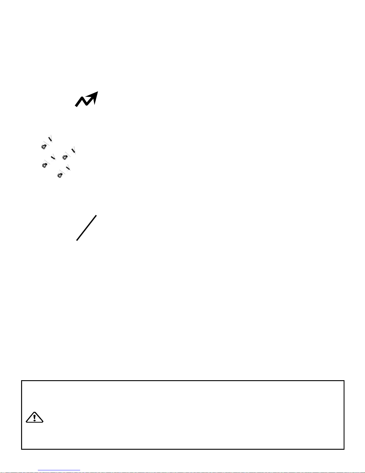
Step 1: Remove contents from box. Attach telescoping tube to the underside of the control
arm using 4x M8x15mm bolts and 4x M8 spring washers.
The control arm is heavy and may swing freely during this stage of
assembly. The Adjuster knob is pre-tightened from the factory in the
optimal position for assembly in relation to the control arm. Do not loosen the Adjuster
knob until the telescoping tube has been safely secured to the underside of the control arm.
CAUTION
E820 Assembly Instructions
4x 8x15mm bolts
and 4x M8 spring
washers
Adjuster knob

5
E820 Assembly Instructions
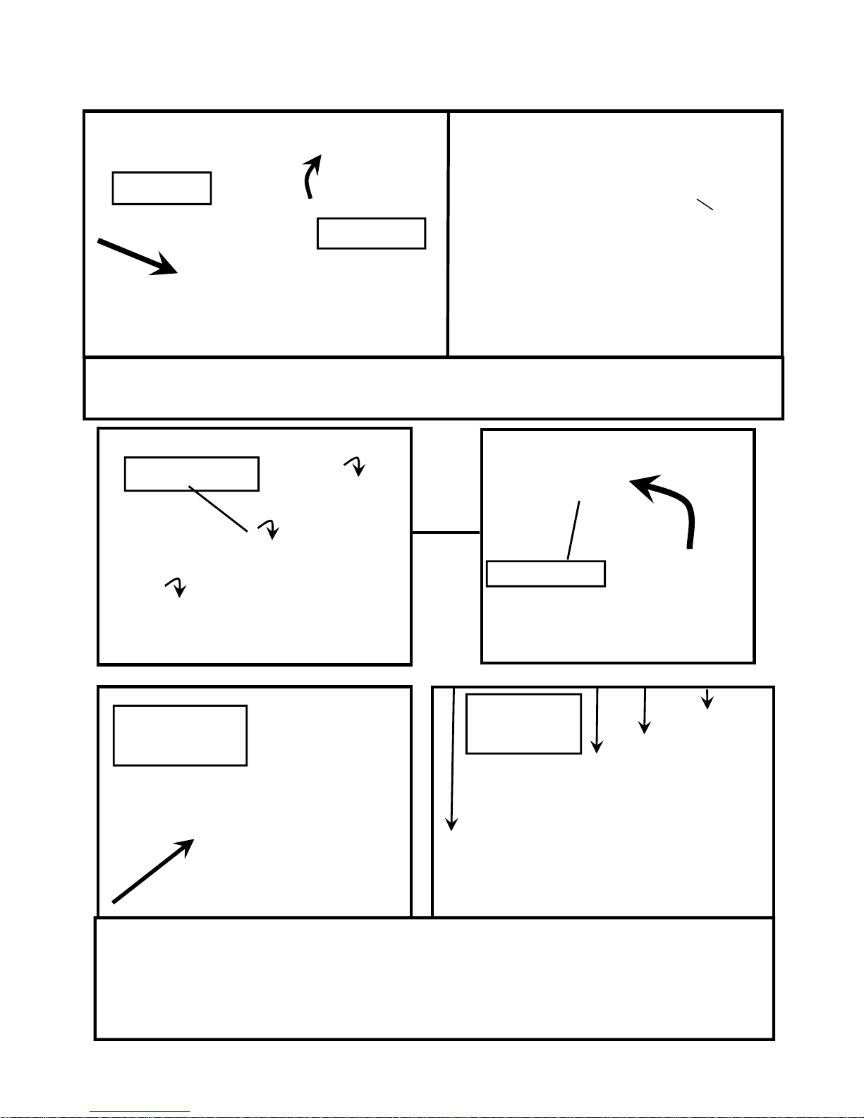
Step 4: Secure right pedal onto Crank arm. The pedal threads have a blue coating which
will feel very tight when threaded onto the crank arm. This is a type of thread locker, and
once in contact with the crank arm threads will activate in approximately 15minutes.
Caution! Extreme over-tightening could damage the aluminum threads on the crank arm.
Note: Allow 15 minutes for the thread
locker to activate before first time use.
Check pedal tightness periodically
thereafter with a 15mm wrench.

6
E820 Baseplate Assembly
Contents:
1x T-Track 2x Footplate
1x Channel Right 1x Bolt Pack (for both baseplate/seat)
1x Channel Left
T-Track
Footplate
Channel
Left
Foot-
Channel
Right
Bolt pack
7
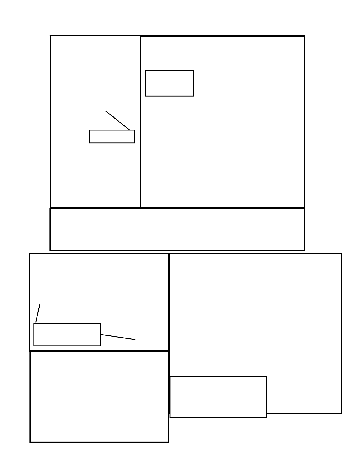
Install the Footplates/Channels:
Step One: Tilt the T-Channel slightly to allow the footplate (with pre-installed bolts)
to slide underneath as shown.
Step Two: Mount the Left Channel over the top of the footplate dome bolts and
then slide forward. Once Channel is properly positioned , attach to T-Track using
4x M8x45mm Bolts.
Repeat this procedure to install Right Footplate and Channel.
Footplate
T-Track
Left Channel
4x 8x45mm
bolts
Slide Channel
forward
Channel Slot
8
Step One: Stand Baseplate upright to install 4x Foot levelers as shown.
Once foot levelers are installed, the completed baseplate can be
installed onto the mainframe of the E820.
Install Baseplate to Mainframe
Step Two: Mount the baseplate onto
the Mainframe using mounting pins as
a locator
Then, secure with 3x M10x25mm Bolt,
2x M10 Nylock Nut and 3x M10 Washer
Note center M10 Bolt does not require
Nut.
Foot leveler
Completed
Baseplate
Baseplate to Mainframe.
3x M10x25mm Bolts, 3x
M10 Washer and 2x M10
Nylock Nuts.
Mounting pins on
E820 Mainframe
9
Install Seat onto Baseplate
Seat Stop: Must be lowered to allow seat onto Baseplate track.
Must ALWAYS be in the LOCKED
position when seat is occupied on
Baseplate.
Must be lowered to allow seat removal.
To LOCK, raise and locate. To
UNLOCK, lift and drop rearward.
Seat Installation: Tilt the seat slightly upward to allow the front rollers to engage the
channel. Then, lift the rear level and, while engaging the Seat Lock Release Lever,
slide the seat onto the Baseplate as shown.
Usage: The seat has four positions. To move forward or rearward, depress the Seat
Lock
Release Lever and move freely to whichever position you require.
CAUTION: The Seat Stop Must be in the LOCKED position whenever the seat is
in use.
To remove the seat: Lift and lower the Rear Safety lock, depress the Seat Lock Re-
lease Lever and slide the seat rearward.
WARNING: Do not under any circumstances attempt to remove/install seat while
occupied.
Seat Stop
 Loading...