

Fluid E820 Owner's Manual
Owners Manual
2
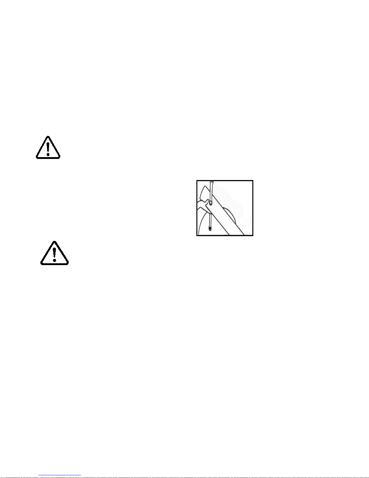
Training with the E820
Do not remove hands while crank is in motion. The crank will
continue to rotate and could cause injury.
As with any piece of fitness equipment, consult a physician before beginning your E820 exercise program.
CAUTION
Use two hands and follow all safety instructions whenever raising
or lowering the E820 control arm.
Warning

3
Contents
Box Contents
Assembly Instructions
Install the Baseplate
Install Baseplate to Mainframe
Seat Assemby
Attaching Armrest Lower frame
Attaching Armrest cable to Cable Pivot
Install Seat Back and Seat
Install Seat onto Baseplate
Control Arm
Tank Filling and Water Treatment
Long Term Water Treatment and Basic Operation
Rower Ergometer
Using the First Degree Fitness USB Interface
Maintenance chart
Troubleshooting
Tank Belt Adjustment
Warranty
4
6
8
10
11
12
14
15
16
17
18
19
20
21
22
23
24
25
4
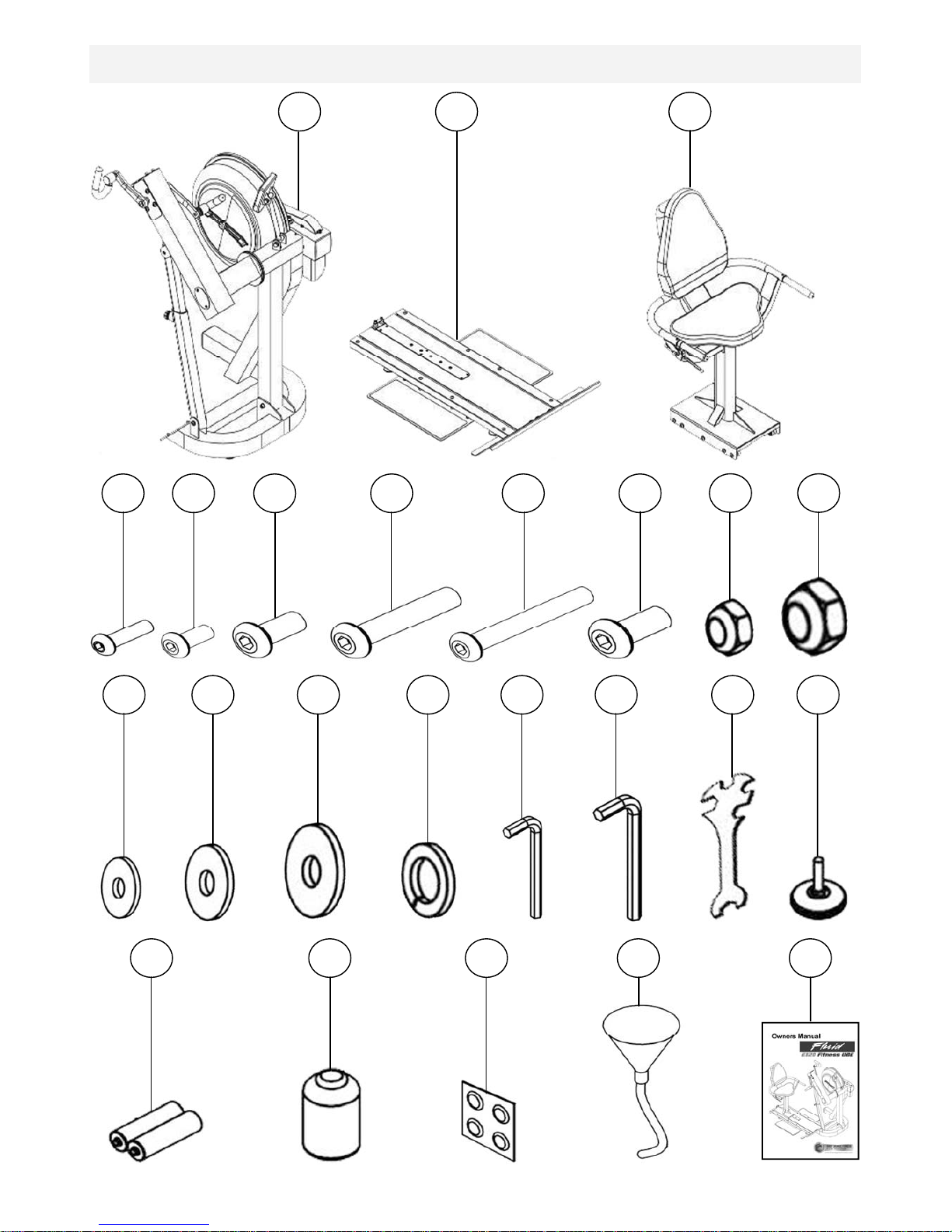
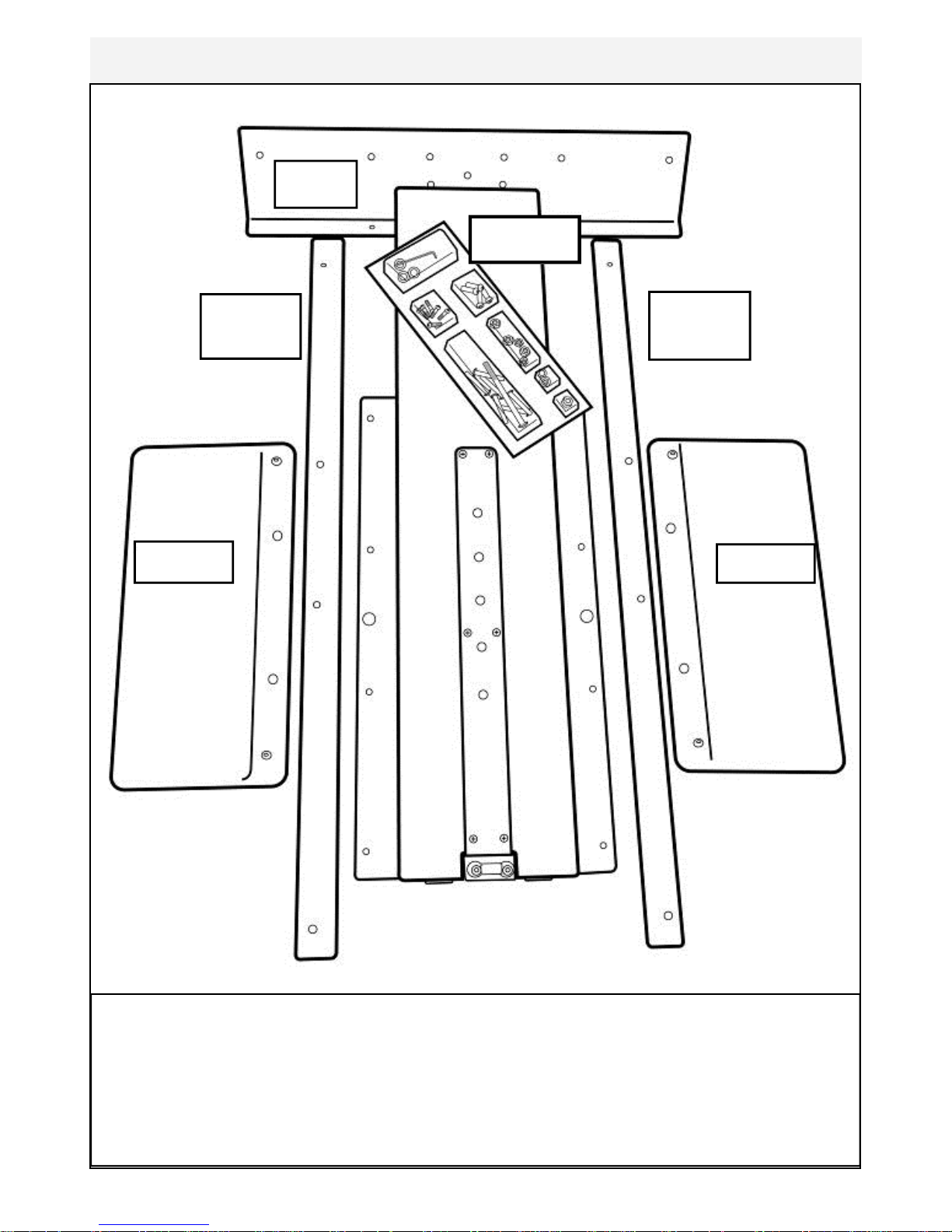
Box Contents
1
10
2
3
4
5
6
7
8
9
11
19
18
17
16
15
14
13
12
20
21
22
23
24

5
Item Qty Description Item Qty Description
1 1
Main Frame with Telescoping
Tube and Internal Gas Assist
Shock
13 4 M8 Washer
2 1 Baseplate (Install P-8) 14 3 M10 Washer
3 1 Seat (Install P-11) 15 4 M8 Springs Washer
4 8 M6x20mm bolt 16 1 4mm Allen Key
5 4 M8x15mm blot 17 1 6mm Allen Key
6 1 M8x25mm blot 18 1 Multi-tool
7 10 M8x45mm blot 19 9 Frame Levelers
8 1 M8x70mm blot 20 2 AA Batteries
12 8 M6 Washer 24 1 Owners Manual
9 4 M10x20mm bolt 21 1 Touch up paint
10 3 M8 Nylock Nut 22 4 Water T reatment Tablet
11 2 M10 Nylock Nut 23 1 Funnel and Hose
6
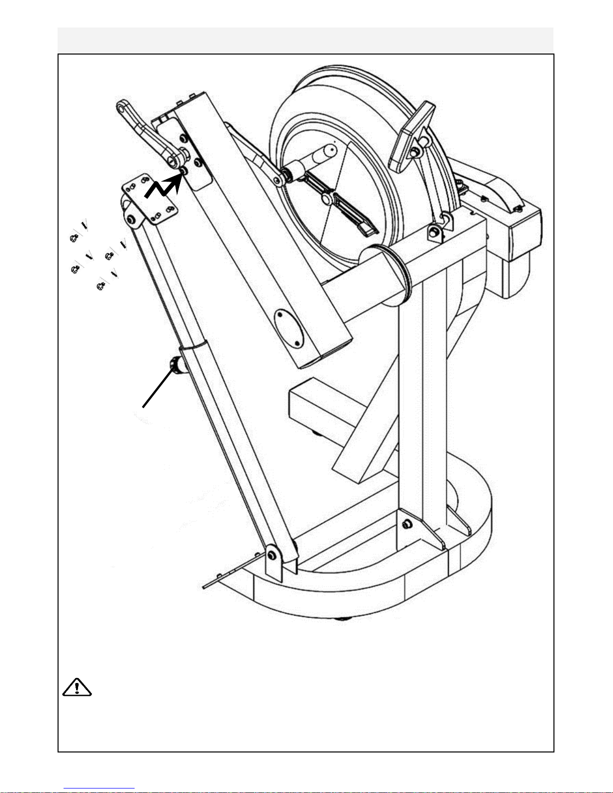
Assembly Instructions
4x 8x15mm bolts
and 4x M8 spring
washers
Adjuster knob
Remove contents from box. Attach telescoping tube to the underside of the control
arm using 4x M8x15mm bolts[5] and 4x M8 spring washers[15].
The control arm is heavy and may swing freely during this
stage of assembly. The Adjuster knob is pre-tightened from
the factory in the optimal position for assembly in relation to the control arm. Do not
loosen the Adjuster knob until the telescoping tube has been safely secured to the
underside of the control arm.
CAUTION

7
Secure right pedal onto Crank arm. The pedal threads have a blue coating which
will feel very tight when threaded onto the crank arm. This is a type of thread locker, and once in contact with the crank arm threads will activate in approximately
15minutes.
Caution! Extreme over-tightening could damage the aluminum threads on the
crank arm.
Note: Allow 15 minutes for the thread
locker to activate before first time use.
Check pedal tightness periodically thereafter with a 15mm wrench.
8
Contents:
1x T-Track 2x Footplate
1x Channel Right 1x Bolt Pack (for both baseplate/seat)
1x Channel Left
T-Track
Footplate
Channel
Left
Footplate
Channel
Right
Bolt pack
Install the Baseplate
 Loading...