

Page 1
Document number:
72.120.601
Document title:
FGM 160 Operating Instructions
Additional Information (when applicable):
E
Removed from User Manual, updated:
modules
Issued for Fluenta release; moved to User
Manual
Rev.
index
Review
by QA
n/a
Scope: ISO 9001:2015 §8.6 Release of products and services
2018.09.17 Updated Abbreviations and removed O&SC AK NB MR MM MB
D 2014.01.20 Proofread and updated JB AP CT MB MW
C 2013.01.30
B 2009.06.02 Updated information AAJ RT N/A N/A AAJ
A 2007.11.30
Issue date Reason for issue Author Review Review
Replacement for:
Fluenta source doc.
(for translations):
changes in text formatting; modifying
graphics in Appendix II and Electronic
n/a
MKJ KH - MW MW
MS RT - N/A AAJ
Approved
Total pages:
27
Page 2

FGM 160 Operating Instructions
72.120.601
Page 2 of 27
TABLE OF CONTENTS
1. Purpose ........................................................................................................................................... 3
2. Abbreviations/Definitions ............................................................................................................. 3
2.1 Abbreviations ......................................................................................................................... 3
2.2 Definitions .............................................................................................................................. 3
3. General Information ....................................................................................................................... 3
3.1 Hardware Description ............................................................................................................ 3
3.1.1 Electrical Connections .............................................................................................. 4
3.1.2 Power Supply ............................................................................................................ 4
3.1.3 Input Signals ............................................................................................................. 4
3.1.3.1 Ultrasonic Transducers ............................................................................. 4
3.1.3.2 Pressure and Temperature Transmitters .................................................. 5
3.1.4 Output Signals .......................................................................................................... 5
3.1.4.1 Modbus Communication (RS-485) ............................................................ 5
3.1.4.2 Foundation Fieldbus Output ...................................................................... 5
3.1.4.3 Current Loop Outputs ................................................................................ 5
3.1.4.4 HART Output ............................................................................................. 5
3.1.4.5 Pulse/Frequency Output ............................................................................ 5
3.1.5 Electronic Modules in FGM 160................................................................................ 6
3.1.5.1 Digital Signal Processing (DSP) Module ................................................... 6
3.1.5.2 Analog Front End (AFE) Module ............................................................... 6
3.1.5.3 Pressure & Temperature (P&T) Module .................................................... 6
3.1.5.4 Input/Output (I/O) Module .......................................................................... 6
3.1.5.5 Intrinsic Safety Barrier (IS Barrier) Module ............................................... 6
3.1.5.6 Surge Protection Module ........................................................................... 6
3.1.5.7 Local Display Module ................................................................................ 6
3.1.6 Non-Resettable Counter Function ............................................................................ 7
3.2 Firmware Description ............................................................................................................. 7
3.2.1 DSP Module .............................................................................................................. 7
3.2.2 P&T Module .............................................................................................................. 8
3.2.3 I/O Module ................................................................................................................ 8
3.3 Device Integrity ...................................................................................................................... 8
3.3.1 Self-Checking ........................................................................................................... 8
3.3.2 Watchdog Timer ....................................................................................................... 8
3.3.3 Flash Memory ........................................................................................................... 8
3.4 Configuration and Operating Software .................................................................................. 9
4. Operating Procedure ................................................................................................................... 10
4.1 Introduction .......................................................................................................................... 10
4.2 Power-Up Sequence ........................................................................................................... 10
4.3 Field Computer Configuration.............................................................................................. 10
4.4 Local Display Functions ....................................................................................................... 11
4.5 Error Check and Troubleshooting ....................................................................................... 12
4.5.1 Error Check with Local Display ............................................................................... 12
4.5.2 Error Check with UFM Manager ............................................................................. 13
5. References .................................................................................................................................... 13
6. Appendix I – System Configuration File .................................................................................... 14
7. Appendix II – Inserting settings from Clie n t parameter list .................................................... 18
Page 3
FGM 160 Operating Instructions
72.120.601
Page 3 of 27
1. PURPOSE
This document describes the Fluenta Flare Gas Meter, FGM 160 hardware and software, and
the device integrity.
2. ABBREVIATIONS/DEFINITIONS
2.1 Abbreviations
TFS Transducer Full Size
FGM Flare Gas Meter
2.2 Definitions
Module PC-board with a local controller and a processor
TFS Series T ransducers based on the TFS. See document 72.050.001 f or details on this
range
3. GENERAL INFORMATION
3.1 Hardware Description
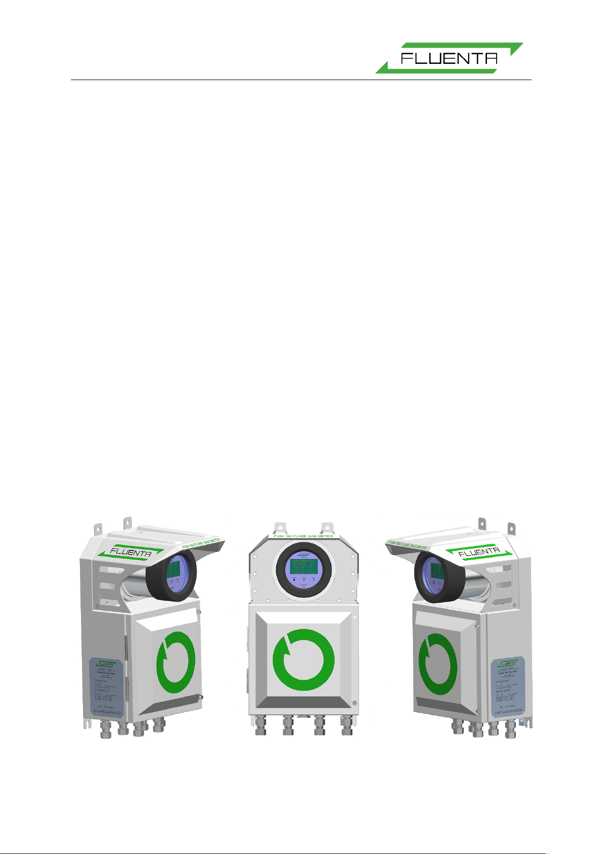
The FGM 160 Field Computer, illustrated in Figure 1, is designed as a distributed system. The
FGM 160 consists of five or six modules, the Digital Signal Processing (DSP) module, the
Analog Front End (AFE) module, the Pressure & Temperature (P&T) module, Input/Output
(I/O) module, Intrinsic Safe Barrier (IS Barrier) module, Surge Protection module and the Local
Display. A distributed system gives several advantages. This design will be more flexible with
respect to future expansions and modifications, as the total processing load for the system can
be divided in several modules. Thus, the danger of overloading a single CPU unit is reduced.
Figure 1: FGM 160 Field Computer.
Page 4
FGM 160 Operating Instructions
72.120.601
Page 4 of 27
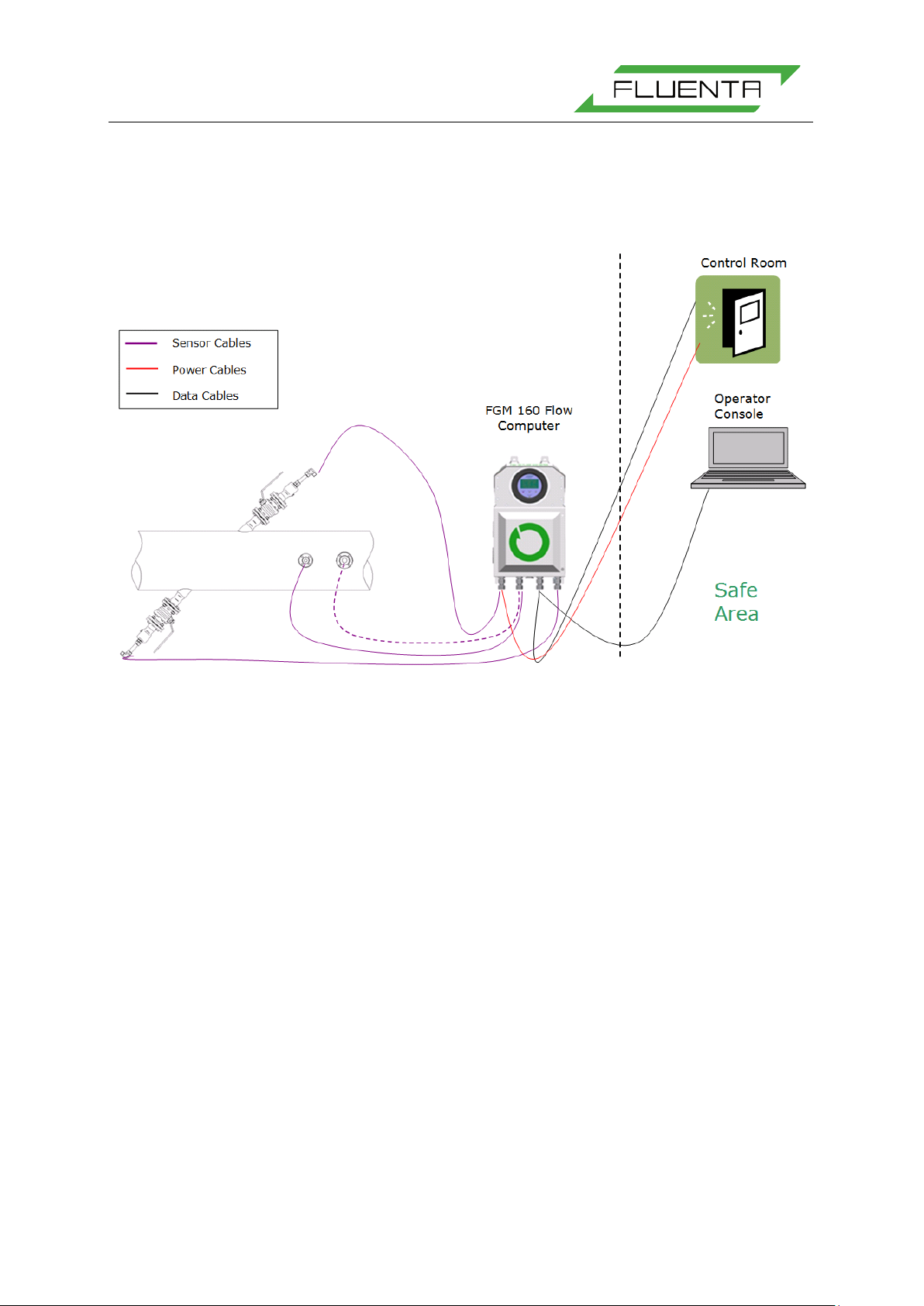
The FGM 160 is certified for operation in Hazardous Area.
For detailed information regarding Hazardous Area installation and operation, please refer to
Fluenta Doc. no. 62.120.006 (Hazardous Area Installation Guidelines [1]) and 75.120.215
(FGM 160 Hazardous Area Certificates [2]).
Figure 2: FGM 160 Hook-Up, with the Field Computer, U l tr asonic T ransducers, Pressure and Temp er atur e
Transmitters, and connections to Safe Area equipment.
3.1.1 Electrical Connections
For detailed information regarding all electrical connections, please refer to Installation & HookUp Instructions [3].
3.1.2 Power Supply
The FGM 160 requires 24 VDC power supply (nominal). If 24 VDC is not available, an optional
110-230 VAC/24 VDC converter can be supplied by Fluenta.
For detailed equipment information and equipment ratings, please refer to Hazardous Area
Installation Guidelines [1].
3.1.3 Input Signals
3.1.3.1 Ultrasonic Transducers
FGM 160 ultrasonic transducers are connected to the FGM 160 Field Computer by means of
prefabricated signal cables included.
Page 5

FGM 160 Operating Instructions
72.120.601
Page 5 of 27
3.1.3.2 Pressure and Temperature Transmitters
The FGM 160 can be configured to accept analog 4-20 mA transmitters or HART compatible
transmitters. The pressure and temperature transmitters may be omitted if the system is
configured to get the pressure and temperature data from the DCS system (Modbus
communication link).
3.1.4 Output Signals
3.1.4.1 Modbus Communication (RS-485)
The FGM 160 has two separate Modbus communication ports.
One is dedicated for communication with a DCS system. The second is a service port for
configuration and monitoring of the FGM 160 system.
In the FGM 160 Foundation Fieldbus configuration, DCS Output is disabled.
3.1.4.2 Foundation Fieldbus Output
A maximum of four (4) parameters can be predefined according to customer requirements.
The list of parameters available for the customer can be found in Fluenta AS doc. No.
72.120.305 (all parameters available by using Modbus Serial Interface are accessible using
Foundation Fieldbus output).
3.1.4.3 Current Loop Outputs
Up to six (6) current loop outputs are availabl e for output of selectable parameter values, w here
three (3) analog outputs are configured as the default. The 4-20 mA current loop output
channels can be configured as active or passive outputs.
4-20 mA Outputs are replaced by FF Outputs in FGM 160 Foundation Fieldbus Configuration.
3.1.4.4 HART Output
One of the current loop outputs can be also configured for HART output communication. Refer
to HART Output Interface Specification [5] for details.
3.1.4.5 Pulse/Frequency Output
The FGM 160 can be also configured to provide a pulse or frequency output si gnal. The pulse
output will represent an incrementation of the totalizer (of e.g. volume or mass), whereas the
frequency output will represent a process parameter (e.g. volume flow rate, mass flow rate
etc.)
Page 6

FGM 160 Operating Instructions
72.120.601
Page 6 of 27
3.1.5 Electronic Modules in FGM 160
3.1.5.1 Digital Signal Processing (DSP) Module
The Digital Signal Processing module is the processing module in the system. The DSP
Module generates the ultrasound measurement signals and controls the measurement
sequences. It collects data from the other module registers and performs flow calculations
based on this data. All calculated parameters are stored in defined registers. All of these
registers are available for UFM Manager software through the Modbus service port at the I/O
Module. A selection of these registers is also available for the DCS system (through the DCS
port at the I/O Module).
3.1.5.2 Analog Front End (AFE) Module
The Analog Front End Module is the interface between the DSP Module and the ultrasonic
transducers via the IS-Barrier unit. At the AFE Module, measurement signals are multiplexed
and switched between upstream and downstream direction.
3.1.5.3 Pressure & Temperature (P&T) Module
The Pressure & Temperature Module collects pressure and temperature information from
external sensors via 4-20 mA current loop or HART Interface. All pressure and temperature
data are stored in predefined registers available for the DSP Module. Accordingly, th e DSP
unit can retrieve P&T parameters in a minimum amount of time.
3.1.5.4 Input/Output (I/O) Module
The Input/Output Module is the interface between the FGM 160 in hazardous areas and
equipment in safe areas. At the I/O Module, 24 VDC (nom.) supply voltage is converted to the
required operational voltages for the other modules. Furthermore, all signals and
communications to and from the DCS system and UFM Manager are handled by this unit.
3.1.5.5 Intrinsic Safety Barrier (IS Barrier) Module
The Intrinsic Safety Barrier Module ensures the intrinsic safety for operation of the ultrasonic
sensors mounted in hazardous area. In addition, the IS-Barrier Module includes safety barriers
for the P&T transmitters. Therefore, the P&T transmitters with “Ex i” certification can be
interfaced directly to the FGM 160. For specifications regarding the P&T transmitter barriers,
please refer to Hazardous Area Installation Guidelines [1].
3.1.5.6 Surge Protection Module
The Surge protection Module protects the power input and the signal output lines from
externally generated spikes, surges and overvoltage.
3.1.5.7 Local Display Module
The Local Display (LD) Module is the front unit, visible through the Ex-d safety glass. At the
LD, a set of predefined metering process parameters can be viewed. In addition, four LEDs
give the status of Power, Alarms, Measurement and Communication.
Page 7
FGM 160 Operating Instructions
72.120.601
Page 7 of 27
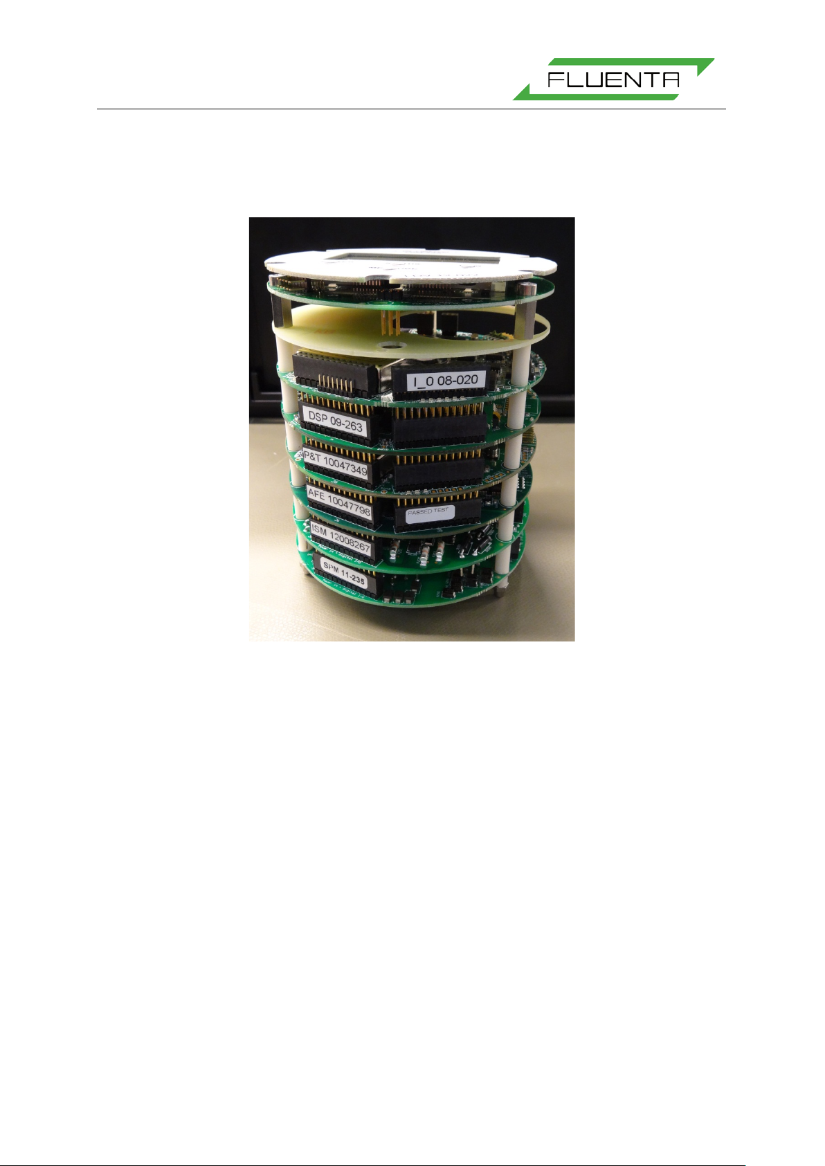
3.1.6 Non-Resettable Counter Function
The non-resettable counter function will record and keep the totalized volume and mass. The
totalized values are accessible through the DCS Modbus interface or through UFM Manager.
Figure 3 Electronic modules
3.2 Firmware Description
In the following sections a general description of the firmware for the different modules is
outlined.
3.2.1 DSP Module
• The DSP Module initializes the system at start-up. Tasks are set to initial states and
the system is ready for operation.
• The signals transmitted by the ultrasound transducers are generated by the DSP
Module. The sequencing is controlled by this module, and, depending on the velocity
of the medium in the pipe, either both Chirp and CW signals or just Chirp signals are
used for the flow measurements. One ultrasonic transit time measurement is always
succeeded by an ultrasonic transit time measurement in the opposite direction.
• Data sampling and signal processing are carried out after a specified number of
sequences. Then, the DSP module calculates the difference in transit time
measurements and calculates the parameters available in the FGM system.
• Flow velocity and volume flow rate calculations run continuously, calculating new
values based on data from the P&T module and transit time measurements from the
ultrasonic transducers.
Page 8

FGM 160 Operating Instructions
72.120.601
Page 8 of 27
• Gas density and mass flow calculations are calculated based on calculated velocity of
sound and measured pressure and temperature.
• Volume and mass totalising calculations are continuously updated based on volumetric
and mass flow rate calculations.
• All system configuration parameters are stored in the Flash memory (non-volatile
memory) at the DSP Module.
• The DSP Module carries out self-checking and evaluation of input and calculated
parameters.
3.2.2 P&T Module
• The P&T Module continuously collects pressure and temperature values from the
external pressure and temperature transmitters mounted downstream of the FGM 160.
These readings are used in calculations performed by the DSP module.
• In addition to the external temperature reading, the P&T also reads the internal
temperature value. This value is used to monitor the internal temperature in the Ex-d
enclosure.
3.2.3 I/O Module
• The I/O Module handles all signals and communication with systems in Safe Area.
• Data requests and commands from UFM Manager are processed by the I /O Modul e. A
predefined number of accessible parameters are available from the FGM. Accessible
parameters depend on whether 4-20 mA, HART or Modbus is utilized.
• Software downloads to the DSP-, P&T - and I/O Module are carried out by the I/Omodule.
• All data requests from DCS system are handled by the I/O Module; either through
Modbus or HART interfaces.
3.3 Device Integrity
3.3.1 Self-Checking
The FGM 160 performs a self-checking sequence, where it checks that inputs from the
transducers and Temperature and Pressure transmitters are within a valid range, and that
other functions are operating as intended.
3.3.2 Watchdog Timer
The Watchdog Timer is initialized at start-up, and cannot be disabled, ensuring that in the
unlikely situation of system hang-up occurring, the Watchdog Timer will reset the system
forcing a complete reboot and start-up.
3.3.3 Flash Memory
System configuration is stored in Flash Memory (non-volatile memory). In case of a power
break, all system configurations are reloaded from the Flash memory
Page 9

FGM 160 Operating Instructions
72.120.601
Page 9 of 27
3.4 Configuration and Operating Software
Through the FGM 160 Ultrsonic Flare Meter Manager (UFM Manager), the operator can
monitor process data, configure the meter and specify process data to be saved to a data log
file for later analysis. UFM Manager further enables the operator to operate the meter remotely,
by using e.g. a RS 485/TCP/IP converter and remote control software.
It should be noted, UFM Manager is required to replace the default settings with actual
applicable settings provided by customer. Fluenta service engineers and partners will always
set up the FGM 160 according to the latest submitted parameters from the Client when
installing and commissioning the FGM 160. Fluenta service engineers and partners always
have the UFM Manager with them.
Page 10

FGM 160 Operating Instructions
72.120.601
Page 10 of 27
4. OPERATING PROCEDURE
4.1 Introduction
This section provides information about how to op erate the FGM 160 field computer. The FGM
160 is a field mounted stand-alone ultrasonic gas flow measurement system, and does not
require any safe area communication device in order to operate. However, in order to
continuously monitor data and the meter performance, it is recommended to use the UFM
Manager software package. This program will provide hands-on process and status data
continuously with possible remote access to the FGM 160 system from any remote system
with the appropriate remote control software installed.
4.2 Power-Up Sequence
The power-up sequence describes the necessary handling of the FGM 160 in order to ensure
correct operation. The power-up sequence is as follows:
1. Connect all power, input and output signals and communication cables according to
the project specification and all relevant procedures and instructions.
2. Make sure that the power cable is connected to a suitable pow er source, ei ther directly
to a 24 VDC supply or through a 110-240 VAC/24 VDC converter.
3. Turn on the power to the FGM 160. There is no power switch on the FGM 160 Field
Computer, so the power must be switched by an external switch or similar, preferably
in safe area.
4. On startup, the FGM 160 will go through a boot and an initialization sequence before
entering the standard operational (measurement) mode.
5. When the FGM 160 has entered the standard operational (measurement) mode, the
meter will, according to the system configuration, carry out t ransit ti me me asurements,
retrieve pressure and temperature data, calculate volumetric and mass flow rates and
either actively output a set of predefined parameters at the analog 4-20mA outputs, or
make a set of process parameters available for DCS HART or Modbus communication.
4.3 Field Computer Configuration
The FGM 160 can be configured by using UFM Manager. During manufacturing, default
configuration is entered into the Field Computer. The system configuration will be modified by
Fluenta service engineers or partners when installing and commissioning the meter. This
configuration can be changed at any time by using The UFM Manager software. All system
configuration parameters are stored in a non-volatile memory, ensuring that no configuration
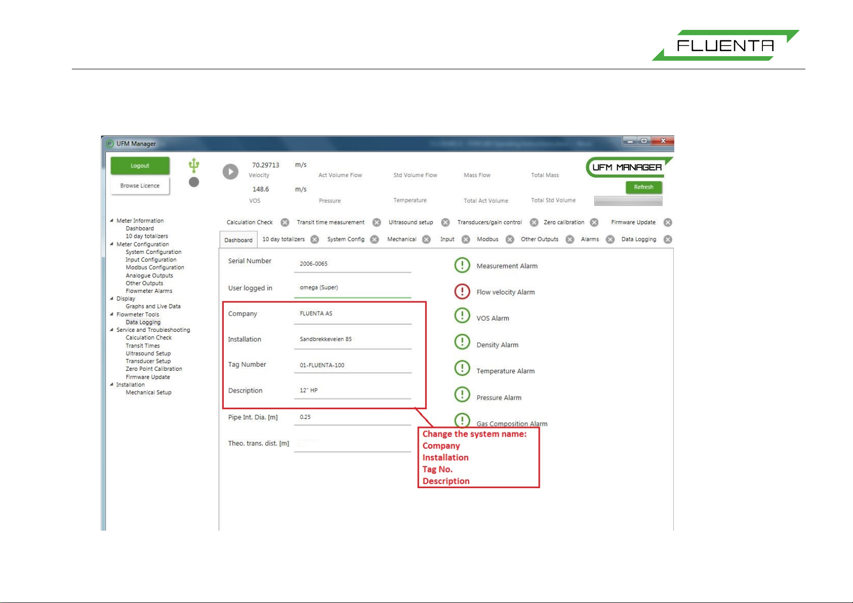
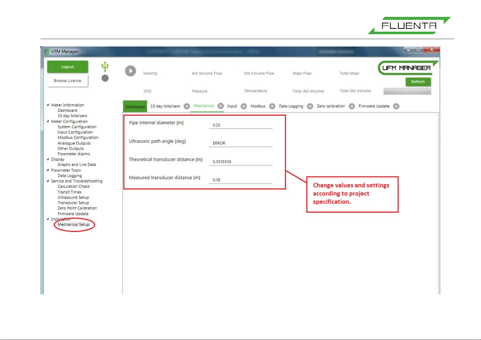
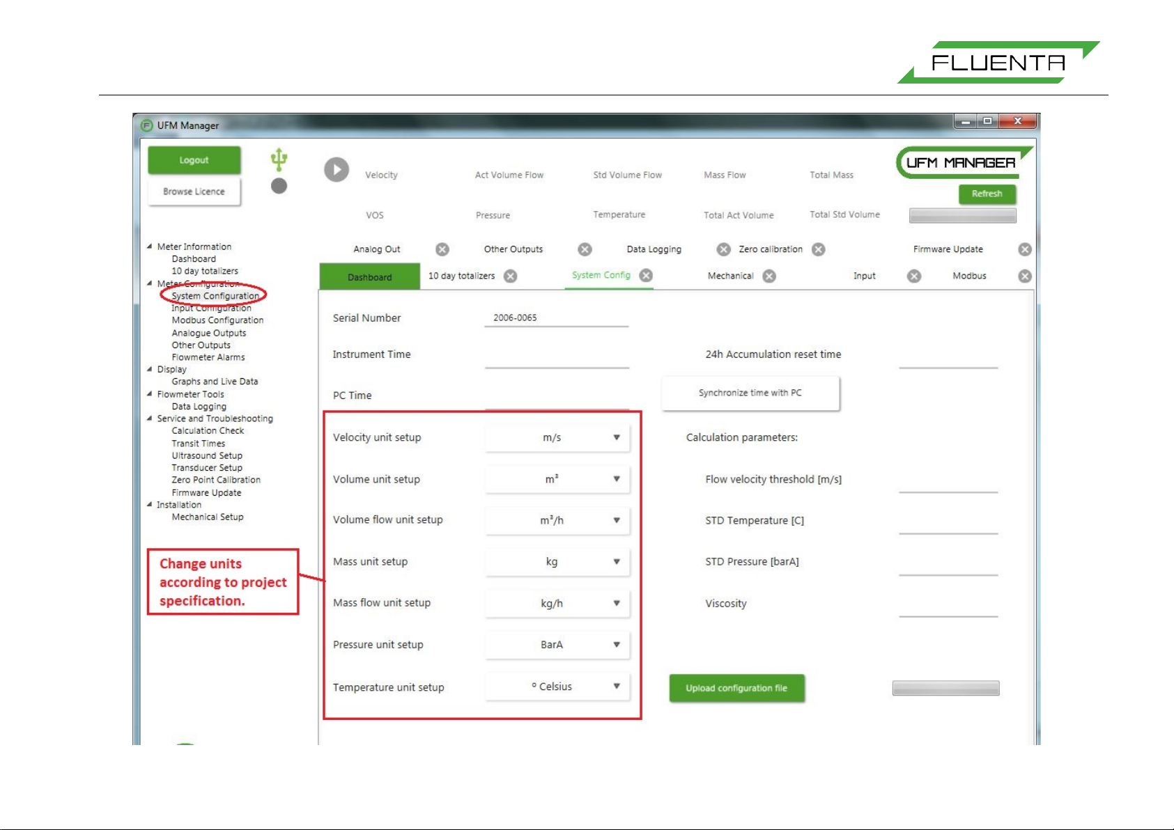
parameters are lost in case of power loss. Appendix II explains how to insert or modify system
configuration according to a Client parameter list.
Page 11
FGM 160 Operating Instructions
72.120.601
Page 11 of 27
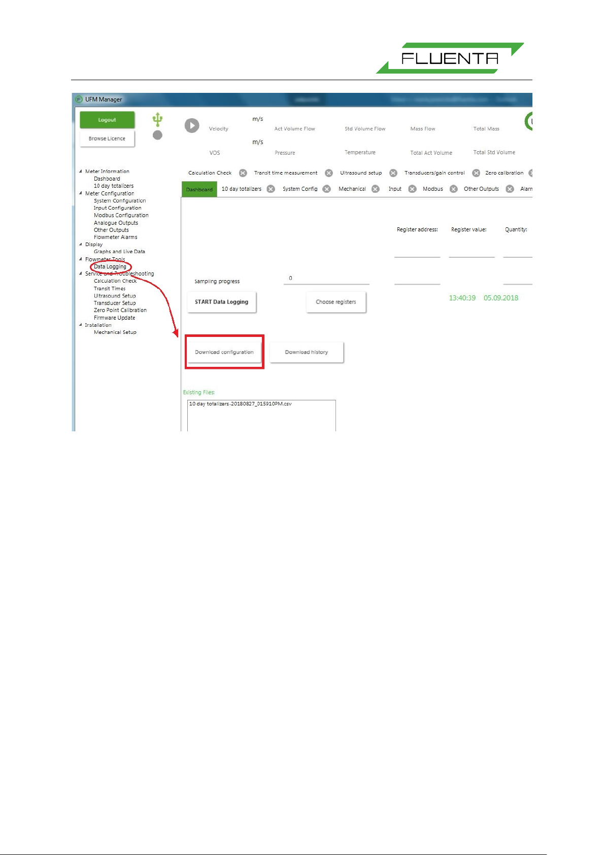
Figure 4: Download of system configuration using the UFM Manager.
The system configuration parameter file can be downloaded from the FGM 160 using the UFM
Manager, ref. Figure 4, by pressing the “Download configuration” button in the “Data Logging”
tab. The system configuration can either be copied to the clipboard and pasted into a
document, or saved directly to a file.
For a full listing of a system configuration file, refer to Appendix I.
Some of the system configuration parameters are also available through the DCS Modbus
registers. However, parameters that should only be accessed by authorized personnel are not
accessible through this communication line. For a full listing of accessible configuration
parameters through the DCS Modbus interface, refer to DCS Modbus Interface Specifications
[4].
4.4 Local Display Functions
The FGM 160 is equipped with a local LCD display mounted at the front, and visible through
the Ex-d safety glass. The display shows predefined process parameters from the FGM 160.
Further, 4 status LEDs are visible at the front for the following status information:
• Power
This LED will have a green light when the system power is ON.
• Status
This LED will light:
GREEN; if no Alarms are active (system status OK).
Page 12

FGM 160 Operating Instructions
72.120.601
Page 12 of 27
• Comm
This LED will light:
GREEN; during Modbus frame reception or sending.
• Meas
This LED will blink GREEN at a regular cycle, indicating that ultrasonicmeasurement cycle
sequence is active.
4.5 Error Check and Troubleshooting
The operator should not perform extensive troubleshooting bey ond the sc ope that is desc ribed
in this section. For repair and module replacement, contact Fluenta AS.
Fluenta AS
Haraldsgate 90
P.O. Box 420
N-5501 Haugesund
NORWAY
Phone: +47 21 02 19 27
E-mail: support@fluenta.com
NOTE!
Before any work can be carried out with the FGM 160 field computer, a hot work permit
must be obtained.
Do not connect or disconnect any signal wires unless the power is turned OFF!
Do not open the Ex-d enclosure containing the field electronics in hazardous area,
without making sure first that the conditions permit such action. Preferably, and as a
general rule; the Ex-d enclosure should only be opened indoors in e.g. a workshop in
safe area.
4.5.1 Error Check with Local Display
As described in Section 4.4, Four (4) LEDs are visible at the front with status information. If
one or more of these LEDs do not have a GREEN light color indicating OK status, the following
status is present and actions should be taken:
• Power
Indication: The LED is not ON (no green light).
Status: System Power is OFF, or LED does not work.
Action: Check that the system Power wires are connected and that 24 VDC is
present at the power input terminals.
• Meas
Indication: The LED is steady OFF or steady GREEN.
Status: The FGM 160 is not in standard operational (measurement) mode.
Page 13

FGM 160 Operating Instructions
72.120.601
Page 13 of 27
Action: Check the Alarm log for any error messages indicating any cause for the
problem. Turn the system Power OFF and ON again. If the situation
remains unchanged, contact Fluenta AS for guidance.
4.5.2 Error Check with UFM Manager
Through the FGM 160 UFM Manager, data can be logged for trend analysis and evaluation.
Figure 5: By pressing the “START Data Logging” butt on at the “Data Logging” tab, a ny or most par ameter s
can be logged to a data file. The data log file name will be generated automatically based on the current
date and time. The registers for the data log can be chosen by pressing the “Choose registers” button.
5. REFERENCES
[1] FGM 160 – Hazardous Area Installation Guidelines
[2] FGM 160 – Hazardous Area Certificates
[3] FGM 160 – Installation & Hook-Up Instructions
[4] FGM 160 – DCS Modbus Interface Specifications
[5] FGM 160 – HART Output Interface Specification
Page 14

FGM 160 Operating Instructions
72.120.601
Page 14 of 27
EXAMPLE
6. APPENDIX I – SYSTEM CONFIGURATION FILE
********************************************************
********************************************************
****************** ***************
****************** Fluenta AS ***************
****************** FGM 160 parameter list ***************
****************** ***************
********************************************************
********************************************************
UFM Manager ver.: 1.040
Field Computer, date and time: 2011-01-17 09:13:25
***************************************
********** System Parameters **********
***************************************
Field Computer Type: FGM 160
Serial number: 2006-0102
Tag number: 1-TAG-1
Company: FLUENTA AS
Installation: Sandbr ekk eveien 85
Description: 10" LP Flare
System Configuration: Single system (ch1)
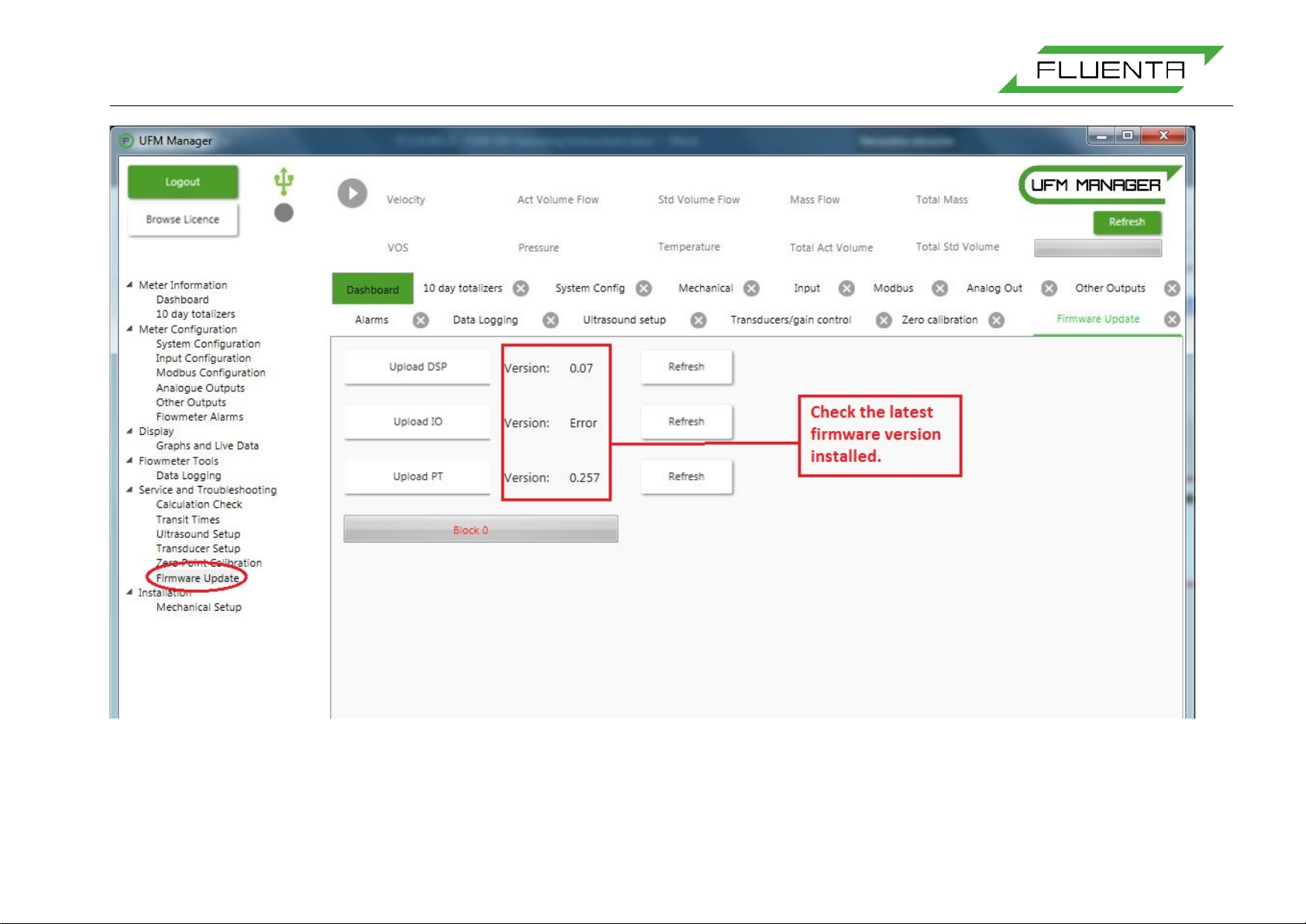
Local Display: Not installed <- You have to change it manually
SW Version DSP: 0.052 to version number that is installed
SW-app Version I/O: 1.007 using AVR Studio
SW-boot Version I/O: 0.006
SW-app Version P&T: 0.257
SW-boot Version P&T: 0.005
*******************************************
********** Communication Parameters **********
*******************************************
**************** DCS communication **********
------------------------------------------------------------
DCS Modbus Communication: Enabled
Slave address: 224
Type: RTU
Baud rate: 38400
Data bits: 8
Parity: No Par ity
Stop bit: 2
Register Values: 32 bit floating point (IEEE-754)
Register size in request: 32 bits
Register base address: 1000
***************** HART communication **********
---------------------------------------------------------------
Page 15

FGM 160 Operating Instructions
72.120.601
Page 15 of 27
EXAMPLE
HART Output Communication: Enabled
Poll address: 1
Primary Variable: Total Volume @ Ref. Conditions
Secondary Variable: Volume Flowrate @ Ref. Conditions
Tertiary Variable: Temperature
Quaternary Variable: Pressure
**************** Service port *****************
-------------------------------------------------------------
Slave address: 1
Type: RTU
Baud rate: 38400
Data bits: 8
Parity: None
Stop bits: 2
Register Values: 32 bit floating point (IEEE-754)
**********************************************
************ System Configuration ************
**********************************************
Pipe diameter: 0.3800 m
Transducer distance (M): 0.5370 m
Transducer angle: 45.0 deg
******* Units *******
Velocity: m/s
Volume: m3
Volume flow: m3/h (Cubic meter pr. hour)
Mass: kg
Mass flow: kg/h
Pressure: BarA
Temperature: Celsius
Log time for 24h acc. values: 06:00:00
**********************************************
*********** Input Signal Parameters ***********
**********************************************
Pressure input Current Loop (4-20mA)
Temperature input Current Loop (4-20mA)
Current loop ranges
Temperature, 4mA value: 255.15 [Kelvin]
Temperature, 20mA value: 533.15 [Kelvin]
Pressure, 4mA value: 1.013 [BarA]
Pressure, 20mA value: 12.044 [BarA]
Current loop calibration coefficients
Tempe rature, offset: 0.0070
Page 16

FGM 160 Operating Instructions
72.120.601
Page 16 of 27
EXAMPLE
Temperature, scale: 0.9963
Press ure, offset: 0.0220
Pressure, scale: 0.9980
Alarm limits
Temperature, Hi limit: 533.15 [Kelvin]
Temperature, Lo limit: 255.15 [Kelvin]
Pressure, Hi limit: 12.044 [BarA]
Pressure, Lo limit: 1.013 [BarA]
**********************************************
********** Output signal parameters **********
**********************************************
******** Current loops, 4-20mA ********
Current loop 1, Parameter: Volume Flowrate @ Act. Conditions
Current loop 2, Parameter: Molecular Weight
Current loop 3, Parameter: Testvalue Current Loop 3
Current loop 4, Parameter: Testvalue Current Loop 4
Current loop 5, Parameter: Testvalue Current Loop 5
Current loop 6, Parameter: Testvalue Current Loop 6
Current loop ranges
Current loop 1, 4mA value: 0.00
Current loop 1, 20mA value: 2124000.00
Current loop 2, 4mA value: 0.00
Current loop 2, 20mA value: 50.00
Current loop 3, 4mA value: 4.00
Current loop 3, 20mA value: 20.00
Current loop 4, 4mA value: 4.00
Current loop 4, 20mA value: 20.00
Current loop 5, 4mA value: 4.00
Current loop 5, 20mA value: 20.00
Current loop 6, 4mA value: 4.00
Current loop 6, 20mA value: 20.00
Current loop calibration coefficients
Current loop 1, offset: -0.1217
Current loop 1, scale: 0.9980
Current loop 2, offset: -0.1647
Current loop 2, scale: 1.0045
Current loop 3, offset: -0.1633
Current loop 3, scale: 1.0018
Current loop 4, offset: -0.2105
Current loop 4, scale: 1.0025
Current loop 5, offset: -0.0232
Current loop 5, scale: 1.0078
Current loop 6, offset: -0.1358
Current loop 6, scale: 1.0058
**********************************************
******** Measurement/Signal Parameters *******
**********************************************
Page 17

FGM 160 Operating Instructions
72.120.601
Page 17 of 27
EXAMPLE
CW velocity limit up (CW/Chirp -> Ch ir p) : 15 m/s
CW velocity limit down (Chirp -> CW/Chirp): 14 m/s
Chirp Pattern: LinFM
Chirp Limit1 (ArcTan FM -> Lin FM): 25 m/s
Chirp Limit2 ( Lin FM ->ArcTan FM): 50 m/s
Low cutoff velocity: 0.05 m/s
Max. velocity: 100 m/s
Min. velocity: 0 m/s
Max. velocity ju mp: 50 m/s
Max. sound velocity: 500 m/s
Min. sound velocity: 250 m/s
Max. sound velocity jump: 70 m/s
Historical sound vel. weight factor: 40.0
Z Standard: 1.000
Z Operational: 1.000
Ref Temperature (std. conditions): 15.00 ºC
Ref Pressure (std. conditions): 1.01325 BarA
**********************************************
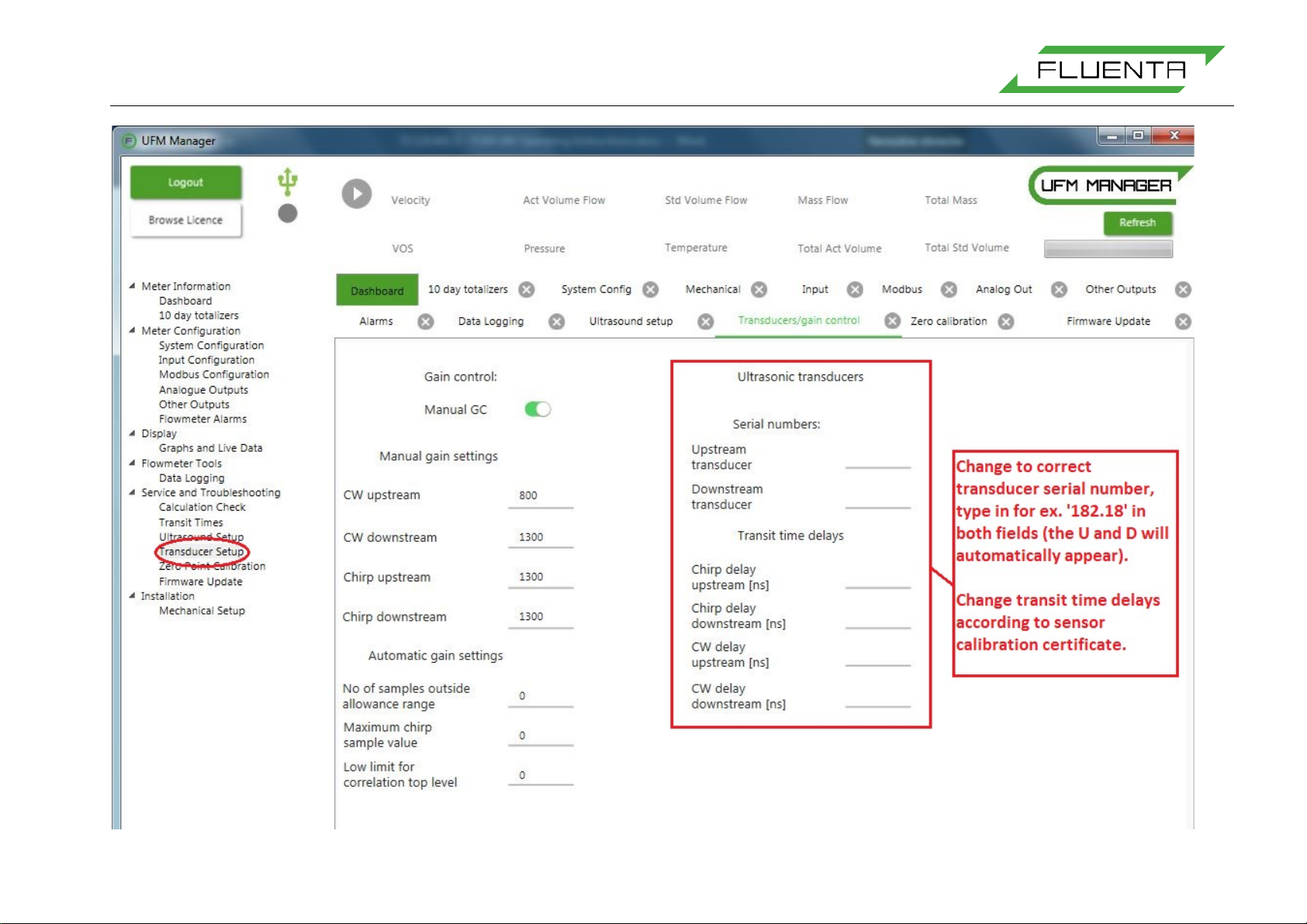
******** Sensor Calibration Parameters *******
**********************************************
Serial No., Upstream Transducer (A): 022U-11
Serial No., Downstream Transducer (B): 022D-11
CW frequency: 68.00 kHz
*** Transducer delays (calibration coefficients) ***
Chirp upstream: 31818.0 nsec
Chirp downstream: 33318.0 nsec
CW upstream: 12557.0 nsec
CW downstream: 12576.0 nsec
Delta CW correction: 0.0 nsec
---------------- END --------------------------
Page 18
FGM 160 Operating Instructions
72.120.601
Page 18 of 27
7. APPENDIX II – INSERTING SETTINGS FROM CLIENT PARAMETER LIST
Page 19

FGM 160 Operating Instructions
72.120.601
Page 19 of 27
Page 20
FGM 160 Operating Instructions
72.120.601
Page 20 of 27
Page 21
FGM 160 Operating Instructions
72.120.601
Page 21 of 27
Page 22

FGM 160 Operating Instructions
72.120.601
Page 22 of 27
Page 23

FGM 160 Operating Instructions
72.120.601
Page 23 of 27
Page 24

FGM 160 Operating Instructions
72.120.601
Page 24 of 27
Page 25

FGM 160 Operating Instructions
72.120.601
Page 25 of 27
Page 26
FGM 160 Operating Instructions
72.120.601
Page 26 of 27
Page 27
FGM 160 Operating Instructions
72.120.601
Page 27 of 27
 Loading...