

Page 1
F3.2
0 Paddlewheel Flow Sensor
1
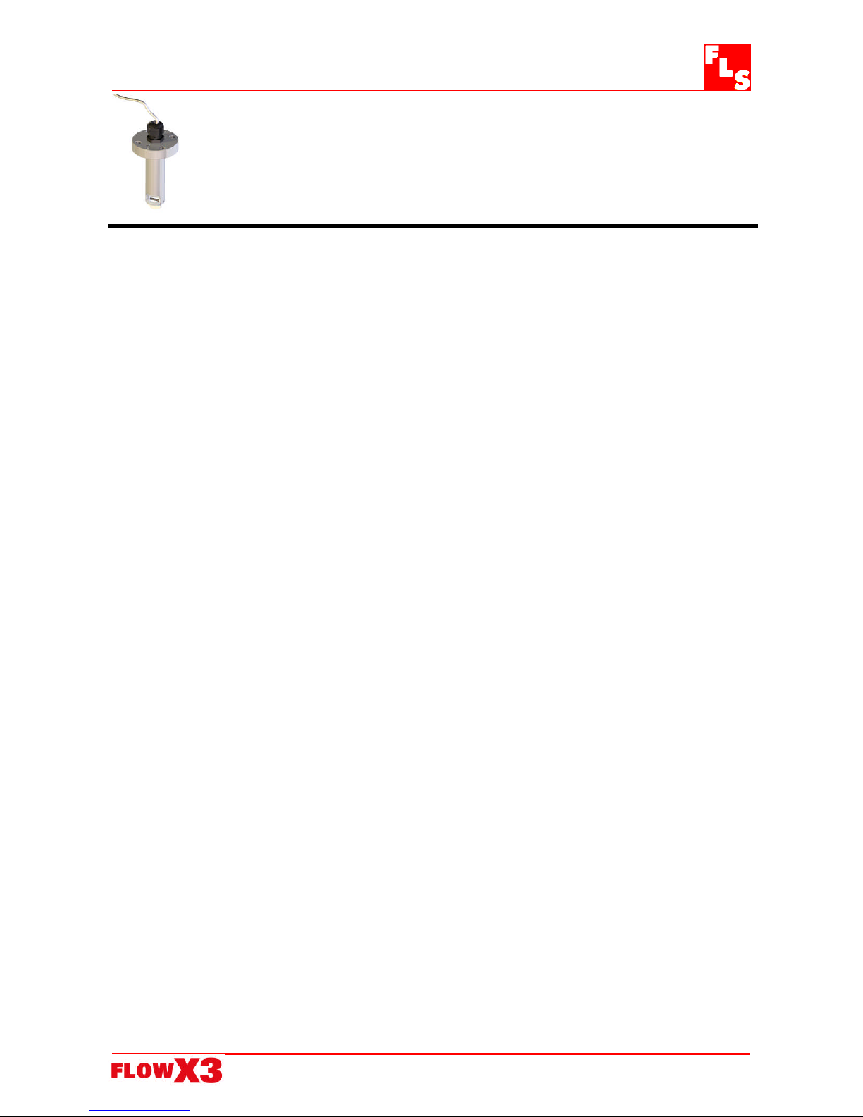
F3.20 High Pressure Paddlewheel Flow Sensor
INSTRUCTION MANUAL
EN 12-02
Table of Contents
1. Introduction………………………………………………………………… 2
1.1. Safety Instructions……………………………………………………..……………2
1.2. Unpacking……………………………………………………………………….…… 2
2. Description…………………………………………………….……………. 2
2.1. Design…………………………………………………………………..……………..2
2.2. Operating Principle………………………………………………………………..... 3
2.3. Connection to FlowX3 Instruments……………………………………………... 3
3. Specifications……………………………………………………………… 3
3.1. Technical Data…………………………………………………………………….… 3
4. Installation………………………………………………………………….. 4
4.1. Location…………………………………………………………………………….... 4
4.2. Mounting Position………………………………………………………………..… 5
4.3. Process Connection……..……………………………………………………...… 5
4.4. Wiring…………………………………………………………………………………. 6
5. Installation Fittings……………………………………………………….. 7
6. K-Factor Tables……………………………………………………………. 7
7. Ordering Data……………………………………………………………… 8
8. Weld-on Adapters installation procedure …………………………….. 9
Page 2

F3.2
0 Paddlewheel Flow Sensor
2
1. Introduction
1.1. Safety Instructions
General Statements
The sensor F3.20.X.XX has only been designed to measure the flow of liquids.
Do not install and service the sensor without following the Instruction Manual.
This sensor is designed to be connected to other instruments which can be
hazardous if used improperly. Read and follow all associated instrument
manuals before using with this sensor.
Sensor installation and wiring connections should only be performed by qualified
staff.
Do not modify product construction.
Installation and Commissioning Statements
Remove power to the sensor before wiring any connection.
Depressurize and vent the system before installing or removing the sensor.
Check and confirm the chemical compatibility of the materials in contact with the
liquid.
Do not exceed maximum temperature/pressure data.
To clean the sensor, use only chemical compatible products.
1.2. Unpacking
Please verify that the product is complete and without any damage. The following
items must be included:
F3.20 Paddlewheel Flow Sensor
Instruction Manual for F3.20 Flow Sensor
2. Description
2.1. Design
The simple and reliable paddlewheel flow sensor type F3.20 is designed for use with
every kind of solid-free liquids and to be installed on high pressure plants. The sensor
can measure flow from 0.15 m/s (0.5 ft/s) producing a frequency output signal highly
repeatable. A rugged construction and a proven technology guarantee exceptional
performances with little or no maintenance required. A specially designed family of
fittings ensures an easy and quick installation into all pipe materials in sizes from DN40
to DN200 ( 1 ½” to 8”.).
Page 3

F3.2
0 Paddlewheel Flow Sensor
3
2.2. Operating Principle
The flow sensor consists of a transducer and a five-blade open cell paddlewheel using
insertion technology. The paddlewheel is equipped with a permanent magnet
integrated into each blade. As the magnet passes close to the transducer a pulse is
generated. When liquid flows into the pipe, the paddlewheel is set in rotation
producing a square wave output signal. The frequency is proportional to the flow
velocity. The sensor is installed into the pipe using a wide range of insertion type
fittings supplied by the flow sensor manufacturer.
2.3. Connections to FlowX3 Instruments
FlowX3 Instruments
FlowX3
Sensors
F9.00 F9.01 F9.02 F9.30 F9.20 F9.50 F9.51 PLC
F3.20.H X X X X X X
F3.20.P X
* with Output KIT mounted
3. Specifications
3.1. Technical Data
Pipe Size Range: DN40 to DN200 ( 1 ½” to 8” ) . Refer to Installation Fittings section for
more details
Flow Rate Range: 0.15 to 8 m/s (0.5 to 25 ft./s)
Linearity: 0.75 % of full scale
Repeatability: 0.5 % of full scale
Minimum Reynolds Number Required: 4500
Temperature : 120 °C ( 248 °F )
Pressure : 110 bar ( 1600 psi)
Enclosure: IP68
Wetted Materials:
Sensor Body: 316L SS
Flat Gasket : graphite
Rotor: ECTFE (Halar)
Shaft: 316L SS
Standards & Approvals
Manufactured under ISO 9002
CE
Page 4

F3.2
0 Paddlewheel Flow Sensor
4
Specific for F3.20.H
Supply voltage: 5 to 24 VDC regulated
Supply current: < 30 mA @ 24 VDC
Output signal: square wave
Output frequency: 45 Hz per m/s nominal (13.7 Hz per ft/s nominal)
Output type: transistor NPN open collector
Output current: 10 mA max.
Cable length: 8 m (26.4 ft) standard, 300 m (990 ft) maximum
Specific for F3.20.P
Supply voltage: 12 to 24 VDC regulated
Supply current: < 30 mA @ 24 VCC
Output signal: square wave
Output frequency: 45 Hz per m/s nominal (13.7 Hz per ft/s nominal)
Output type : Push – Pull (digital input NPN or PNP)
Output current : I
Out
Max < 20 mA
Cable length: 8 m (26.4 ft) standard, 300 m (990 ft) maximum
4. Installation
4.1. Location
Different pipe configurations and obstacles in the flow line such as valves, elbows, pipe
bends and strainers create variations on the flow profile.
Whenever possible follow the EN ISO 5167-1 installation recommendations to locate
the sensor.
Always maximize distance between flow sensor and pump.
Page 5

F3.2
0 Paddlewheel Flow Sensor
5
4.2. Mounting Position
Make sure the pipeline is always full.
Horizontal pipe runs:
Fig. 1: installation with no sediments present
Fig. 2: installation with no air bubbles present
Fig. 3: installation if sediments or air bubbles may be present
Vertical pipe runs:
Install sensor in any orientation. Upward flow is preferred to ensure full pipe.
4.3. Process Connection
1. Place the flat gasket, sensor, and the
screws with washers making sure that the
arrow is in line with the slot milling of the
weld on adapter
2. tighten the screws with a force equal to 15
Nm
Page 6
F3.2
0 Paddlewheel Flow Sensor
6
4.4. Wiring
Always ensure the power supply is switched off before working on the sensor.
Always use a high quality (regulated) DC voltage supply.
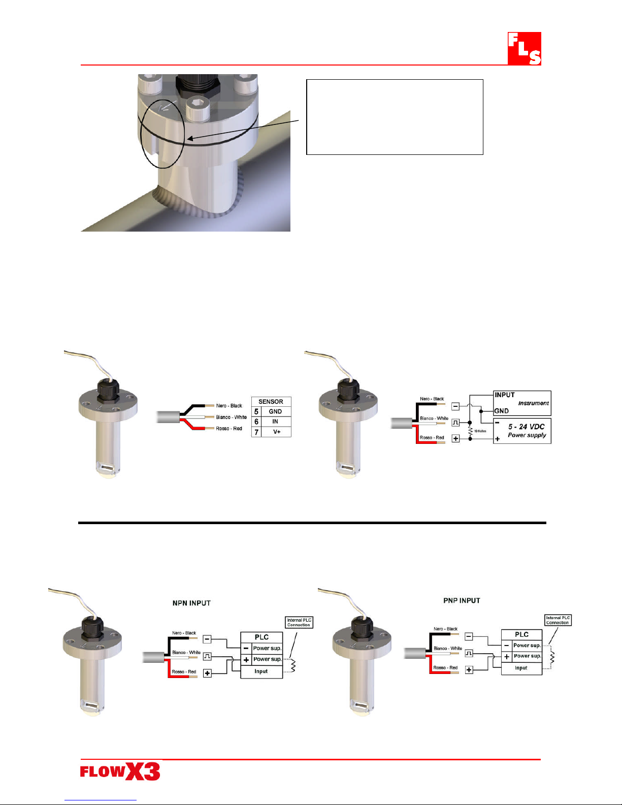
2.7Kohm Pull-up resistor may be required.
N.B. The slot milling of the weld
on adapter must be parallel to
the flow. The arrow on the
sensor must be close to the
milling weld on adapter.
F3.20.H IP68 Sensor Connection to
FlowX3 Instruments
F3.20.H IP68 Sensor Connection
to Other Brand Instruments
F3.20.P IP68 Sensor to PLC with
NPN Input
F3.2
0.P IP68 Sensor to PLC with
NPN Input
Page 7

F3.2
0 Paddlewheel Flow Sensor
7
5. Installation Fittings
Type Description
316L SS Weld-on
Adapters
Size: DN 40 to DN 200 ( 1 ½” to 8” )
6. K-Factor Tables
K-Factor is the number of pulses a sensor produces for one liter of fluid measured. Here
all K-Factors for water at ambient temperature are listed.
K-Factor values can depend upon the installation conditions.
Please contact your dealer for K-Factor values not included in the tables.
316L SS Weld-on Adapters mounted on 316L SS Weld-on Adapters mounted on
Cast Iron pipes Other Metal pipes
Part No. DN K-Factor Part No. DN K-Factor
WAIXL0 40
---------
WAIXL0 40
36,17
WAIXL0 50
---------
WAIXL0 50
23,71
WAIXL0 60
19,78
WAIXL0 60
---------
WAIXL0 65
---------
WAIXL0 65
13,93
WAIXL0 80
10,22
WAIXL0 80
9,61
WAIXL0 100
6,01
WAIXL0 100
5,22
WAIXL0 110
---------
WAIXL0 110
---------
WAIXL0 125
3,64
WAIXL0 125
3,31
WAIXL0 150
2,46
WAIXL0 150
2,22
WAIXL0 175
---------
WAIXL0 175
---------
WAIXL0 200
1,28
WAIXL0 200
1,23
Page 8
F3.2
0 Paddlewheel Flow Sensor
8
7. Ordering Data
FlowX3 F3.00.H.XX (Remote version)
Part No. Version Power supply Length Body Enclosure
F3.20.H.01 Hall 5 - 24 VDC L0 INOX IP68
F3.20.P.01 Push-Pull 12 - 24 VDC L0 INOX IP68
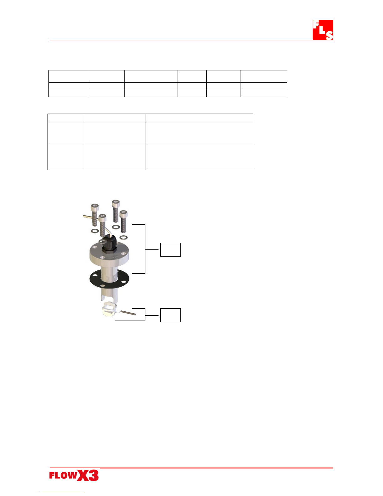
Spare Parts
Item Part No. Description
A-1
F3.SP4.3 ECTFE (Halar) rotor with Inox Shaft
A-2 F3.SP8
flat gasket + screws
A-2
A-1
Page 9

F3.2
0 Paddlewheel Flow Sensor
9
8. Weld-on Adapters installation procedure
Calculate the length A and mark it on the adapter.
Measure the adapter diameter at the mark level and drill the hole in the pipe with
such diameter.
Insert the adapter into the pipe and to be sure that the milling slot is parallel to the
flow (see drawing n°2)
Weld the adapter at the above mark reference.
See drawing n°1.
Drawing n°1 Drawing n°2
The milling slot
must be parallel
to
the flow
Flow rate direction
A = 0.12 x di + 3.5 + S
Page 10

F3.2
0 Paddlewheel Flow Sensor
10
Page 11

F3.2
0 Paddlewheel Flow Sensor
11
Page 12

F3.2
0 Paddlewheel Flow Sensor
12
F.I
.P.
Formatura Iniezione Polimeri S.p.A.
Loc. Pian di Parata, 16015 Casella (GE) – Italy
Tel +39 010 96211 – Fax +39 010 9621209
www.flsnet.it
 Loading...