


Strömungswächter | FS
30
MONTAGE- UND EINSTELLANLEITUNG
Flow Monitor | FS
30
INSTRUCTIONS FOR INSTALLATION AND ADJUSTMENT
M_FS 30_0315_d_e

GMBH
Strömungswächter | FS
30
2
Please follow these installation, connection
and adjustment instructions carefully.
Failure to comply, or misuse of this equipment, could
result in serious damage both to the equipment
itself and to the installation. FlowVision is unable
to accept responsibility for customer or third party
liability, warranty claims or damage caused by
incorrect installation or improper handling resulting
form non-observance of these instructions.
Diese Anleitung unterstützt Sie beim
Einbau, Anschließen und Einstellen des
Niveauwächters.
Eine Nichtbeachtung der Montage- und
Bedienungsanleitung kann zu erheblichen Schäden
am Gerät und an der Anlage führen. FlowVision
übernimmt gegenüber Kunden oder Dritten keine
Haftung, Gewährleistung oder Garantie für Mängel
oder Schäden, die durch fehlerhaften Einbau oder
unsachgemäße Handhabung unter Nichtbeachtung
der Montage- und Bedienungsanleitung verursacht
sind.

GMBH
Flow Meter | FS 30
3
BESCHREIBUNG | DESCRIPTION
ON Q
Flow Switch
SET
GERMANY
36 41
ø39
SW 27
G 1 A
Taster zur
Schaltpunkteinstellung
momentary switch for switch point
adjustment
M12x1
1.53
1.61
1.42
1.06
GMBH
77
ø39
SW 27
G 1/2“A
M12x1
41
1.06
1.53
1.61
1.61
77
ø39
SW 27
NPT 1/2“
M12x1
41
1.06
1.53
1.61
1.61
1 Description
The flow monitor FS30 is designed to monitor the
flow of water and signals if the value falls below a
pre-settable MIN limit value. Important operational
safety and reliability enhancing features designed
and built into these units include:
• Calorimetric flow monitoring, which avoids the
need for moving parts in the flow stream.
• The desired MIN switch point is steplessly adjustable via a teach-in momentary switch on the
front side of the unit.
• If the value falls below the pre-set MIN switch
point, this is indicated by an LED (yellow) on the
front side of the unit and forwarded via a 500
mA switching signal (HSS transistor output).
• Screw-in type ½” or 1” monitoring head for
installation in the pipe system to be monitored.
Fig. 1
1 Beschreibung
Der Strömungswächter FS30 überwacht die
Strömung des Mediums Wasser und signalisiert das
Unterschreiten eines einstellbaren MIN-Grenzwerts.
• Die Überwachung erfolgt - ohne mechanisch
bewegte Teile - nach dem kalorimetrischen Prinzip.
• Der gewünschte MIN-Grenzwert ist über einen
Teach-in-Taster auf der Vorderseite des Geräts
stufenlos einstellbar.
• Das Unterschreiten des eingestellten MINGrenzwerts wird von einer LED (gelb) auf der
Vorderseite des Geräts angezeigt und über ein
500 mA-Schaltsignal (HSS Transistorausgang)
weitergeleitet.
• Das Kompaktgerät wird mit seinem standardisierten ½” oder 1” Schraubmesskopf in die zu
überwachende Rohrleitung montiert.

GMBH
Strömungswächter | FS
30
4
TECHNISCHE DATEN
2 Technische Daten
Überwachungsbereich Strömung:
flüssige Medien min. 0,25 m/s
max. 3,00 m/s
zul. Mediumstemperatur 1 °C … 70 °C
zul. Umgebungstemperatur -15 °C … 55 °C
Druckfestigkeit Messkopf 16 bar
Ansprechzeit:
Wasser ca. 5 s *
* Verzögerungswerte gemessen bei Schalt-
punkt einstellung auf 1 m/s und einer
Betriebsströmung von 2 m/s nach plötzlichem
Strömungsstillstand.
Schutzart:
Messkopf IP 67
Nennspannung: DC 12 V (9 … 16 V)
DC 24 V (18 … 32 V)
- Kennzeichnung gemäß den Bestimmun gen
der EG-Richtlinie 2004/108/EG.
Störaussendung: EN61000-6-2
Störfestigkeit: EN61000-6-3
2 Technical Data
Flow rate range:
liquids 0.25 m/s (0.82 inch/s) minimum
3.0 m/s (9,84 ft./s) maximum
Temperature range:
of the medium 1 °C … +70 °C
(33.8 °F to +158 °F)
of the control unit -15 °C … +55 °C
(5 °F to +131 °F)
Pressure resistance
of the monitoring head: 16 bar/233 PSI
Response delay:
water approx. 5 s *
* Delay with the switch point set to 1 m/s (3.3
ft./s) and the flow rate at 2 m/s (6.6 ft./s), after
a sudden complete flow stoppage.
Degree of protection:
Monitoring head IP 67
Input voltage: DC 12 V (9 … 16 V)
DC 24 V (18 … 32 V)
- mark to demonstrate compliance with applicable directive 2004/108/EC.
Emitted interference: EN61000-6-2
Immunty to interference: EN61000-6-3
GMBH
Flow Meter | FS 30
5
TECHNICAL DATA
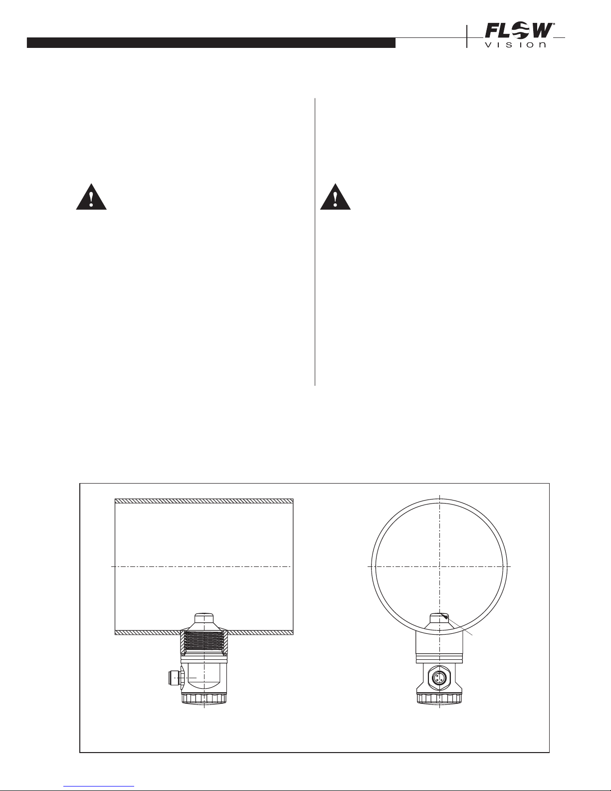
Fig. 2
3 Strömungswächter montieren
1 Überprüfen, ob der einzubauende Strömungs-
wäch ter für das Strömungsmedium ausgelegt ist.
Achtung!
Beim Ein- und Ausbau des Strömungswäch ters überzeugen Sie sich, dass das
Rohrsystem nicht unter Druck steht.
2 Den Einbauort des Strömungswächters wie folgt
wählen (siehe Fig. 2):
a Um Strömungsturbulenzen an dem Messfühler
zu vermeiden, den Strömungswächter nur in
gerade Rohrleitungen einbauen. Auf ausreichenden Abstand zu Querschnittsänderungen
und Rohrkrümmungen achten.
Minimal erforderliche Einlauflänge 10 x D und
Auslauflänge 5 x D (nach DIN 1952).
(D = Rohrnennweite)
3 Flow monitor installation
1 Check that the flow monitor is suitable for the
medium to be monitored.
Caution:
While installing or removing the flow monitor
please make sure that the pipe system is
unpressurized.
2 For best performance the flow monitor should be
installed in the pipeline in accordance with the
following conditions (see fig. 2).
a The flow monitor should be installed only in a
straight section of piping. There should be a
distance of at least 10 pipe diameters before
the flow monitor and 5 pipe diameters after
the flow monitor before or after any bends
and changes in pipe diameter, to avoid any
effects of turbulence.
Messfühler
Abbildung zeigt 1“ Variante
image shows 1“ type
S
sensor S

GMBH
Strömungswächter | FS
30
6
INSTALLATION
b In the case of vertical pipelines the flow
should be installed where the flow is rising,
if possible.
c For horizontal pipelines the flow monitor
should be mounted on the underside of the
line (suspended).
d Avoid installing the flow monitor in known
areas of high electrical inductance, capacitance, or high-frequency electromagnetic
fields.
3 The flow monitor should be screwed into the
pipeline far enough to ensure that the sensor
(S) is positioned fully in the flow stream (see fig.
2). However, care should also be taken that the
sensor is not screwed in too far, thus causing
an undue restriction in the pipe bore.
• When tightening the flow monitor FS 30 please
use the flats provided (SW 27) and do not turn
or apply torque to the housing.
• It is important that thread sealing compound or
material of the correct type for the media be used
when fitting the monitoring head.
•
The retention pin ensures correct alignment of the
sensors after the union nut has been tightened.
Before start-up please pressurize the pipe
system and check with regard to leakages
and strength.
Please remove the sensor head‘s red protective
cap before you mount the FS30 flow switch in the
installation.
b Bei senkrechter Leitung möglichst nur in
Steigleitungen einbauen, um falsche Signale
durch Luftpolsterbildung zu vermeiden.
c Bei waagerechter Leitung Strömungswächter
von unten einbauen.
d Um evtl. Funktionsstörungen auszuschließen
sind energiereiche induktive, kapazitive und
hochfrequente Einstreuungen zu vermeiden.
3 Messkopf mit Rohrfitting vergleichen und über-
prüfen, ob der Messfühler (S) im eingebauten
Zustand im Strömungsmedium liegt (siehe Fig.
2), ohne den Rohrleitungsquerschnitt wesentlich
zu verringern.
• Strömungswächter FS 30 mit entsprechendem
Dichtungsmaterial in das vorgesehene Rohrfitting
einschrauben und mit einem Gabelschlüssel (SW
27) an den Schlüsselansatzflächen festziehen.
• Beim Anziehen des Strömungswächters die VDI
Richtlinien 2230 für das Anzugsmoment unbedingt
beachten.
Vor Inbetriebnahme das Rohrsystem unter
Druck setzen und es auf Festigkeit und
Leckagen überprüfen.
Entfernen Sie vor der Installation des Strömungswächters die rote Schutzkappe des Messfühlers.

GMBH
Flow Meter | FS 30
7
INSTALLATION
4 Anschließen
Achtung!
Überprüfen, ob die Versorgungsspannung mit
der Nennspannung des Strömungswächters
übereinstimmt.
1 Verbindung mit dem zugehörigen Kabel entspre-
chend dem Anschlussbild (Fig. 3) herstellen.
2 Versorgungsspannung anschließen. Die grüne
LED (Betriebsanzeige) leuchtet.
4 Electrical connection
Caution!
Check that the supply voltage corresponds
with the voltage rating shown on the system.
1 Connect the supply by means of the appropriate
cable (see fig. 3).
2 Connect power supply. The green LED (status
indication) lights.
3
4
schwarz/black
braun/brown
blau/blue
1
FS 30
+
Last/load
max. 500 mA
–
Meldeausgang
signal output
+UB
-UB
1
braun/brown
+
4
schwarz/black
S-Ausgang/signal output
3
blau/blue
–
Stiftkontakte DIN EN 50044 bzw. IEC 947
M12x1 3-polig
plug-in connector DIN EN 50044 or IEC 947
M12x1 3 pole
Fig. 3
GMBH
Strömungswächter | FS
30
8
INSTALLATION
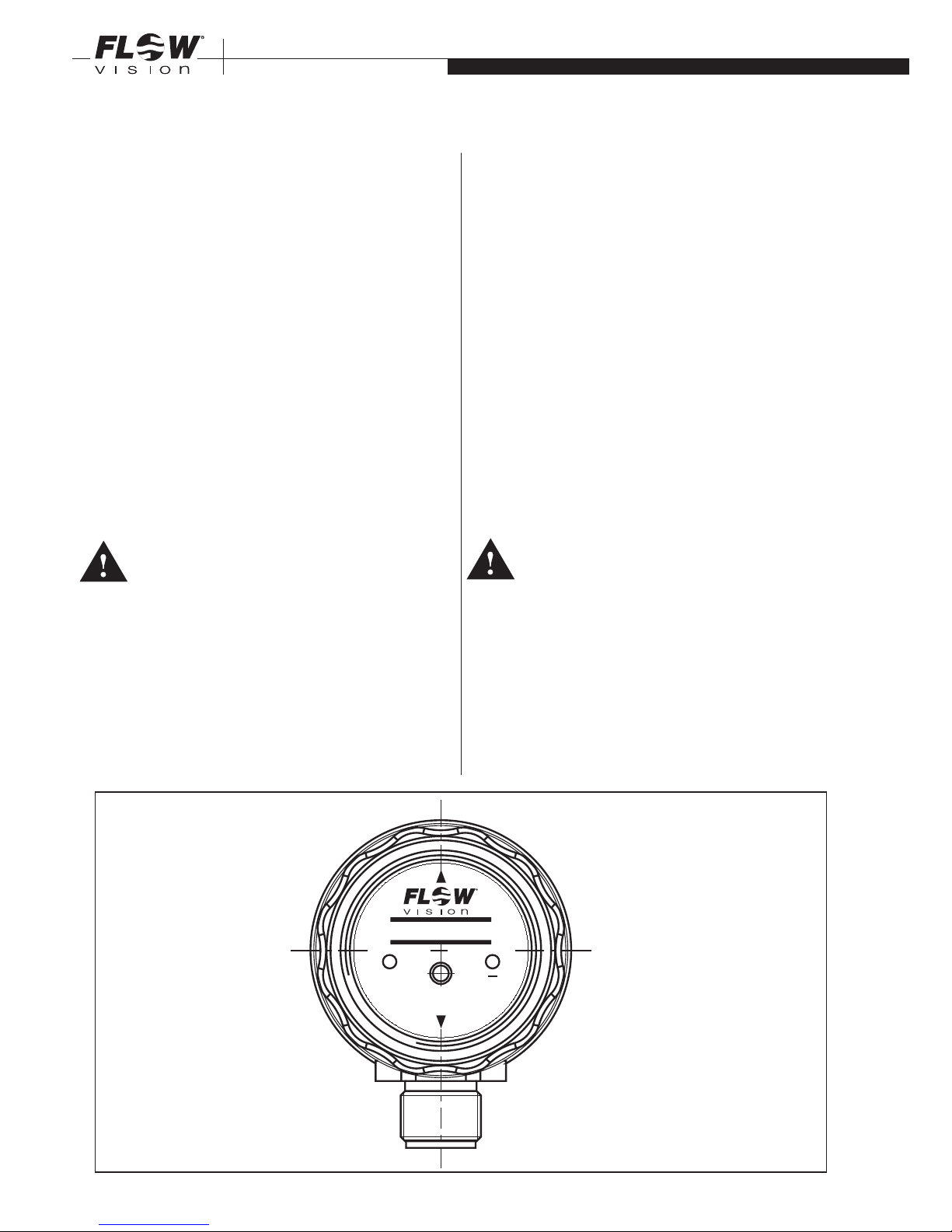
5 Ansprechwert Strömung einstellen
Voraussetzung:
Der Strömungswächter FS 30 ist entsprechend
den Kapiteln 3 und 4 montiert und angeschlossen.
1 Transparenten Frontdeckel abschrauben.
2 In der zu überwachenden Rohrleitung ist die
kritische Strömung mit zugehöriger Temperatur
herzustellen, bei welcher der Strömungswächter
ansprechen soll. Die kritische Strömung kann z.B.
durch Reduzierung der Pumpenleistung oder mittels
Absperrventil in der Leitung erreicht werden.
Die Aufheizzeit des Messkopfes beträgt ca. 5 Min.
Achtung!
Auf laminare und gleichbleibende Strömungsbedingungen achten. In flüssigen Medien ist
Blasenbildung zu vermeiden.
3 Die gelbe LED (_Q) im Strömungswächter zeigt den
momentanen Ist-Bereich des Schaltpunktes an.
Unterschreitet die Strömungsgeschwindigkeit
den mittels SET-Taster eingestellten Wert, so
schaltet der Meldeausgang auf 0 V-Pegel und
die gelbe LED ( _Q) leuchtet.
5 Adjustment of flow response value
Ensure flow monitor has been correctly installed
and connected in accordance with paras. 3 and 4.
1 Loosen the translucent front cover.
2 Start by bringing the system to the critical flow
rate at which the flow monitor should respond
and to its normal operating temperature and
allow it to reach thermal stabilization. This takes
at least 5 minutes.
The critical flow rate can be simulated by redu-
cing the pump power or by means of stop valve
installed in the pipe.
Caution!
Care should be taken to ensure that the
flow is continuous and laminar, and for
liquids free of bubbles (doesn’t apply when
monitoring foam).
3 The yellow LED (_Q) on the Flow Monitor indica-
tes the actual range of response value.
If the flow rate falls below the value adjusted by
means of SET-button, the signal output swit-
ches on 0 V-level and the yellow LED (_Q) lights.
ON Q
Flow Switch
SET
GERMANY
GMBH
Fig. 4

GMBH
Flow Meter | FS 30
9
INSTALLATION
4 Den Schaltpunkt stellen Sie ein, indem Sie kurz
die Teach-in-Taste SET drücken. Die gelbe LED
wird zunächst im 2-Sekunden-Takt blinken und
dann nach ca. 24 Sekunden erlöschen. Damit ist
der Schaltpunkt dauerhaft einprogrammiert.
6 Wartung
Der Strömungswächter ist wartungsfrei bei Medien,
die sich nicht an dem Messfühler festsetzen.
•
Den Messfühler in entsprechenden Erfahrungs-
intervallen von Ablagerungen reinigen.
•
Hierbei mechanische Verletzungen des Messfühlers
vermeiden.
Die Erfahrungsintervalle werden durch periodische
Prüfung des Fühlers festgesetzt.
7 Testmodus mit Filter für
Temperaturschwankungen
Mit dem SET-Taster können Sie hohe Temperaturschwankungen im zu überwachenden Medium
ausfiltern, indem Sie die Ansprechzeit des
Strömungswächters erhöhen.
• Drücken Sie beim Anlegen der Versorgungsspannung gleichzeitig den SET-Taster.
(Hinweis: Sollte jetzt die LED zu blinken anfangen,
sind Sie irrtümlicherweise in den Einstellmodus für
den Schaltpunkt geraten. In diesem Fall schalten
Sie bitte das Gerät sofort wieder aus und beginnen
erneut mit dem Testmodus.)
• Der Filter für Temperaturschwankungen ist jetzt
in Betrieb.
• Um den Testmodus und den Filter wieder auszuschalten, unterbrechen Sie die Spannungsversorgung. Beim nächsten normalen Zuschalten
der Versorgungsspannung (ohne Betätigung des
SET-Tasters) geht der Strömungswächter automatisch in den Normalbetrieb über und arbeitet mit
dem eingestellten Schaltpunkt (siehe Punkt 5).
4 For adjustment of switch point, push the teach-in
button SET briefly. The yellow LED will first blink
in a 2-second-cycle and then go out after approx.
24 seconds. The switch point is now permanently
set.
6 Maintenance
FlowVision Flow Monitors are virtually maintenance
free.
However:
•
The monitoring head sensor must be kept free
of deposits.
•
Avoid damaging the sensor during cleaning.
When first installed the flow monitor should be
checked periodically to see if cleaning is required
until an operating pattern is established.
7 Test mode with filter
for variations in temperature
The SET button allows filtering high variations in
temperature in the medium to be monitored by
increasing the response time of the flow monitor.
• When applying the supply voltage push the SET
button at the same time.
(Note: If the LED starts blinking now, you have
erroneously accessed the adjustment mode for the
switch point. In this case please switch the device
off immediately and re-start the test mode.)
• The filter for variations in temperature is now
working.
• For switching test mode and filter off again, interrupt
the voltage supply. When the supply voltage will
be applied next time (without pushing the SET
button) the flow monitor will automatically start
working in the standard mode with the adjusted
switch point (see item 5).

GMBH
Strömungswächter | FS
30
10
8 Störungen beseitigen
Störung:
Ungewolltes Ansprechen des Schaltpunktes.
Beseitigung:
• Bei flüssigen Medien Blasenbildung vermeiden.
• Schaltpunkt auf größeren Abstand zur
Normalströmung legen, besonders bei größeren
Temperaturschwankungen.
•
Überprüfen, ob der Strömungswächter entsprechend den Angaben in Kap. 3 „Strömungswächter
montieren“ eingebaut ist.
•
Strömungswächter ausbauen und Messfühler
reinigen.
Störung:
Schaltpunkt nicht einstellbar.
Beseitigung:
•
Überprüfen, ob der Strömungwächter für das
Strömungsmedium ausgelegt ist.
8 Operating difficulties
Problem:
Incorrect switching
Solution:
•
Avoid bubbles in the medium.
•
Ensure monitoring head has been correctly
installed in accordance with para. 3.
•
Adjust the switch point to permit a greater differential from the normal flow rate, particularly
in the event of a wide temperature range in the
medium.
•
Remove the flow monitor and clean the sensors.
Problem:
Switch point cannot be adjusted.
Solution:
•
Check whether the flow monitor is suitable for
the medium.

GMBH
Flow Meter | FS 30
11

FlowVision GmbH
Im Erlet 6
90518 Altdorf
Telefon 0049 (9187) 9 22 93 - 0
Telefax 0049 (9187) 9 22 93 - 29
info@flowvision-gmbh.de
www.flowvision-gmbh.de
 Loading...