

Flow-tronic Raven-Eye Installation & Operation Manual

Open Channel Non-Contact
RADAR Flow Meter
Installation & Operation Manual
V1.1, September 2013
Rue J.H. Cool 19a | B-4840 Welkenraedt | Tel.: +32 (0)87 899 799 | Fax: +32 (0)87 899 790 | E-mail: info@flow-tronic.com | www.flow-tronic.com


Rue J.H. Cool 19a | B-4840 Welkenraedt | BELGIUM
Tel. : +32 (0)87 899 799 | Fax : +32 (0)87 899 790
E-mail : info@flow-tronic.com | www.flow-tronic.com
CONTENTS
1 SPECIFICATIONS - 3 -
2 GENERAL INFORMATION - 5 -
2.1 SAFETY INFORMATION - 5 -
2.1.1 S
2.1.2 P
2.1.3 C
2.1.4 R&TTE
2.2 P
2.2.1 T
3 INSTALLATION - 9 -
AFETY SYMBOLS AND WARNINGS - 5 -
REC AUTIONARY LABELS - 5 -
ONFINED SPAC E PRECAUTIONS - 6 -
REGULATIONS - 6 -
RODUCT OVERVIEW - 7 -
HEORY OF OPERATION - 8 -
3.1 UNPACK THE INSTRUMENT - 9 -
3.2 M
3.2.1 S
3.2.2 S
3.2.2.1 I
3.2.2.2 A
3.2.2.3 A
3.2.2.4 A
3.2.2.5 A
3.2.2.6 A
3.2.2.7 M
3.2.2.8 M
3.2.2.9 S
3.2.3 M
3.3 E
3.3.1 E
3.3.2 W
ECHANICAL INSTALLATION - 10 -
ITE LOCATION GUIDELINES - 10 -
ENSOR INSTALLATION - 12 -
NSTALL THE MOUNTING HARDWARE ON THE WAL L - 13 -
TTACH THE SENSOR TO THE MOUNTING HARDWARE - 14 -
LIGN THE SENSOR VERTICALLY – RAVEN-EYE® WITHOUT ATTACHED LEVEL SENSOR - 16 -
TTACH THE LEVEL SENSOR - 17 -
LIGN THE SENSOR VERTICALLY – RAVEN-EYE® WITH ATTACHED LEVEL SENSOR - 17 -
LIGN THE SENSOR HORIZONTALLY - 19 -
AKE A FINAL ALIGN ME NT CHECK - 19 -
EASURE THE SENSOR OFFSET - 20 -
ENSOR OFFSET CALCULATION - 21 -
EASURE THE PIPE DIAMETER - 22 -
LECTRICAL CONNECTIONS - 23 -
LECTROSTATIC DISCHARGE (ESD) CONSIDERATIONS - 23 -
IRING - 23 -
4 OPERATION - 24 -
4.1 UNI-TRANS - 24 -
4.2 RTQ-L
4.3 MODBUS
4.3.1 H
4.3.2 P
4.3.3 M
4.3.4 L
OGGER SERIES - 24 -
ASCII - 24 -
OW DOES IT WORK? - 24 -
ARAMETERS - 25 -
EASU REMENT DATA „READ ONLY“ - 25 -
EVEL INPUT „READ & WRITE“ - 25 -
- 1 -

Rue J.H. Cool 19a | B-4840 Welkenraedt | BELGIUM
Tel. : +32 (0)87 899 799 | Fax : +32 (0)87 899 790
E-mail : info@flow-tronic.com | www.flow-tronic.com
5 MAINTENANCE - 26 -
5.1 PREVENTIVE MAIN TE N A NC E - 26 -
5.2 C
5.3 C
LEANING THE INSTRUMENT - 27 -
ABLE REPLACEMENT PROCEDURE - 27 -
6 REPLACEMENT PARTS AND ACCESSORIES - 28 -
7 CONTACT INFORMATION - 28 -
7.1 FOR BELGIUM AND LUXEMBOURG - 28 -
7.2 O
7.3 T
7.4 R
UTSIDE BELGIUM AND LUXEMBOURG - 28 -
ECHNICAL SUPPORT - 28 -
EPAIR SERVICE - 28 -
APPENDIX - 29 APP. 1 FLOW-TRONIC CUSTOMER SERVICE DEPARTMENT REGISTRATION FORM - 29 -
WARRANTY STATEMENT - 30 -
Copyright © 1989-2013 Flow-T ronic S.A. All printed material s hould not be changed or alter ed without permiss ion
of Flow-Tronic S.A. An y published technical data and instruc tions are subject to change wit hout notice. Contact
your Flow-Tronic representative for current technical data and instructions.
Rue J.H . C ool 19a B-4840 Welkenraedt BELGIUM
Tel. : +32 (0)87 899 799 Fax : +32 (0)87 899 790
E-mail: info@flow-tronic.com www.flow-tronic.com
- 2 -

Rue J.H. Cool 19a | B-4840 Welkenraedt | BELGIUM
Dimensions (W x L x D)
Weight
3,85 kg, without cable and mounting hardware
Enclosure
supply
Temperature error: max. 0,04%/K
be connected to the UNI-TRANS.
1 Specifications
RAVEN-EYE®
Tel. : +32 (0)87 899 799 | Fax : +32 (0)87 899 790
E-mail : info@flow-tronic.com | www.flow-tronic.com
Specifications are subject to change without notice
Operating temperature
Storage temperature
Power requirements
Interconnecting cable (disconnect at
both sensor and logger ends)
Level measurement
Communication
Output
140 x 422 x 183 mm, without cable and mounting hardware
IP68 waterproof rating, polyurethane (PU)
-20 to 50 °C
-30 to 60 °C
Supplied by UNI-TRANS, RTQ-Logger Series or any 4.8 to 24 VDC power
Polyurethane, 8 mm diameter
IP68 < 1bar
Standard length: 10 m ; maximum length: 300 m
Standard Range ultrasonic level sensor (range: 1,75 m) attached to the sensor
using a mounting hardware
Accuracy: 0,3%
Temperature error: max. 0,04%/K
Standard Range ultrasonic level sensor (range: 5,75 m) attached to the sensor
using a mounting hardware
Accuracy: 0,2%
External 4-20 mA loop powered level sensor with correct electrical parameters to
RS-485 with proprietary protocol for use with UNI-TRANS or RTQ-Logger Series
RS-485 with serial MODBUS ASCII slave open protocol for use with PLCs
1 passive analog 4-20 mA (conf igurable for raw surface velocity or analyzed
surface velocity)
Method: Radar
Velocity measurement
Range: ±15 m/s to ±10 m/s (bi-directional)
Frequency Range: 24.075 to 24.175 GHz, <100 mW (EIRP) max.
Accuracy: ±0.5% ±0.02 m/s (based on sensed surface velocity)
®
The RAVEN-EYE
transmitter is certified to the following requirements:
- Frequency: 24,125 GHz - Doppler pulse
CE Directives EMC, R&TTE
Use of this device is subject to the following conditions:
1 There are no used serviceable items inside this device.
Certification
2 The user must install this device in accordance with the supplied installation
instructions and must not modify the device in any manner whatsoever.
3 Any service involving the transmitter must only be performed by
FLOW-TRONIC S.A. or authorized trained personal.
4 The user must ensure that no one is within 20 cm of the face of the radar
transmitter when operating.
R&TTE Directive 1999/5/EC
Approvals
EN 300 440-1 V1.6.1 EMC / ERM 1-40 Ghz Radios : Part 1
EN 300 440-2 V1.4.1 EMC / ERM 1-40 Ghz Radios : Part 2
- 3 -

Rue J.H. Cool 19a | B-4840 Welkenraedt | BELGIUM
Flow measurement
Tel. : +32 (0)87 899 799 | Fax : +32 (0)87 899 790
E-mail : info@flow-tronic.com | www.flow-tronic.com
Method
Accuracy
Based on continuity equation Q = V*A calculated by logger or flow monitor
± 5% of reading typical where flow is in a channel with uniform f low conditions
and is not surcharged, ±1% full scale max.
- 4 -
Rue J.H. Cool 19a | B-4840 Welkenraedt | BELGIUM
Tel. : +32 (0)87 899 799 | Fax : +32 (0)87 899 790
E-mail : info@flow-tronic.com | www.flow-tronic.com
2 General Information
2.1 Safety information
Please read this entire manual before unpacking, setting up, or operating this equipment. Pay attention to all danger
and caution statements. Failure to do so could result in serious injury to the operator or damage to the equipment.
To ensure that the protection provided by this equipment is not impaired, do not use or install this equipment in any
manner other than that specified in this manual.
2.1.1 Safety Symbols And Warnings
Throughout this manual are s afety warning and caution inform ation boxes. Each warning and c aution box will be
identified by a large symbol indicating the type of inform ation contained in the box. The symbols are explained
below:
DANGER
Indicates a potentially or imminently hazardous situation which, if not avoided, will result in
death or serious injury.
WARNING
Indicates a potentially or imminently hazardous situation which, if not avoided, could
result in death or serious injury.
CAUTION
Indicates a potentially hazardous situation that may result in minor or moderate injury.
Important Note: Indicates a situation which, if not avoided, may cause damage to the
instrument. Information that requires special emphasis.
Note: Information that supplements points in the main text.
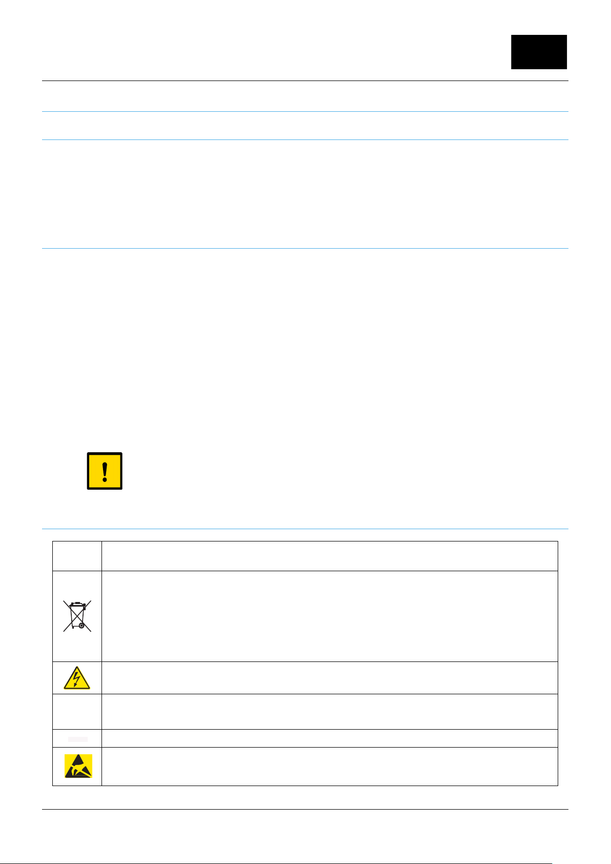
2.1.2 Precautionary labels
This is the safety alert symbol. Obey all safety messages that follow this symbol to avoid potential injury. If on
the instrument, refer to the instruction manual for operation or safety information.
Electrical equipment marked with this symbol may not be disposed of in European public disposal systems
after
12 August of 2005. In conformity with European local and national regulations (EU Directive 2002/96/EC),
European electrical equipment users must now return old or end-of life equipment to the Producer for
disposal at no charge to the user.
Note: For return for recycling, please contact the equipment producer or supplier for instructions on how to
return end-of-life equipment, producer-supplied electrical accessories, and all auxiliary items for proper
disposal.
This symbol, when noted on a product enclosure or barrier, indicates that a risk of electrical shock and/or
electrocution exists.
This symbol, when noted on the product, identifies the location of the connection for Protective Earth
(ground).
This symbol, when noted on the product, identifies the location of a fuse or current limiting device.
This symbol, when noted on the product, indicated the presence of devices sensitive to Electro-static
Discharge
(ESD) and indicated that care must be taken to prevent damage with the equipment.
- 5 -

Rue J.H. Cool 19a | B-4840 Welkenraedt | BELGIUM
Tel. : +32 (0)87 899 799 | Fax : +32 (0)87 899 790
E-mail : info@flow-tronic.com | www.flow-tronic.com
2.1.3 Confined space precautions
DANGER
Confined space entry. Training in pre-entry testing, ventilation, entry procedures, evacuation/rescue
procedures and safety work practices is necessary before entering confined spaces.
Important Note: The following information is provided to guide users of RAVEN-EYE
®
Sensors on the dangers and
risks associated with entry into confined spaces.
Definition of a confined space:
A confined space is an y location or enclosure t hat presents or has the imm ediate potential to pres ent one or more
of the following conditions:
An atm osphere with less than 19.5% or greater than 23.5% oxygen and/or more than 10 ppm H ydrogen
Sulfide (H
S).
2
An atmosphere that may be flammable or explosive due to gases, vapors, mists, dusts or fibers.
Toxic materials which upon contact or inhalation, could result in injury, impairment of health or death.
Confined spaces are not designed for human occupancy. They have restricted entry and contain known or potential
hazards. Examples of confined spaces include manholes, stacks, pipes, vats, switch vaults, and other similar
locations.
Standard safety proc edures must always be followed pr ior to entr y into conf ined spaces and/or locations where
hazardous gases, vap ors, mists, dusts or fibers m ay be present. Before entering an y confined space check with
your employer for procedures related to confined space entry.
DANGER
Explosion hazard. Make sur e your app lication is NOT a n ATEX ra ted and d oes NOT require ATEX cert ified
equipment
2.1.4 R&TTE regulations
Use of this device is subject to the following conditions:
There are no used serviceable items in this device.
The user must install this device in accordance with the supplied installation instructions and must not modify the
device in any manner whatsoever.
Any service involving the transmitter must only be performed by FLOW-TRONIC S.A. or authorized trained
personal.
The user must ensure that no one is within 20 cm of the face of the radar transmitter when operating.
- 6 -
Rue J.H. Cool 19a | B-4840 Welkenraedt | BELGIUM
Tel. : +32 (0)87 899 799 | Fax : +32 (0)87 899 790
E-mail : info@flow-tronic.com | www.flow-tronic.com
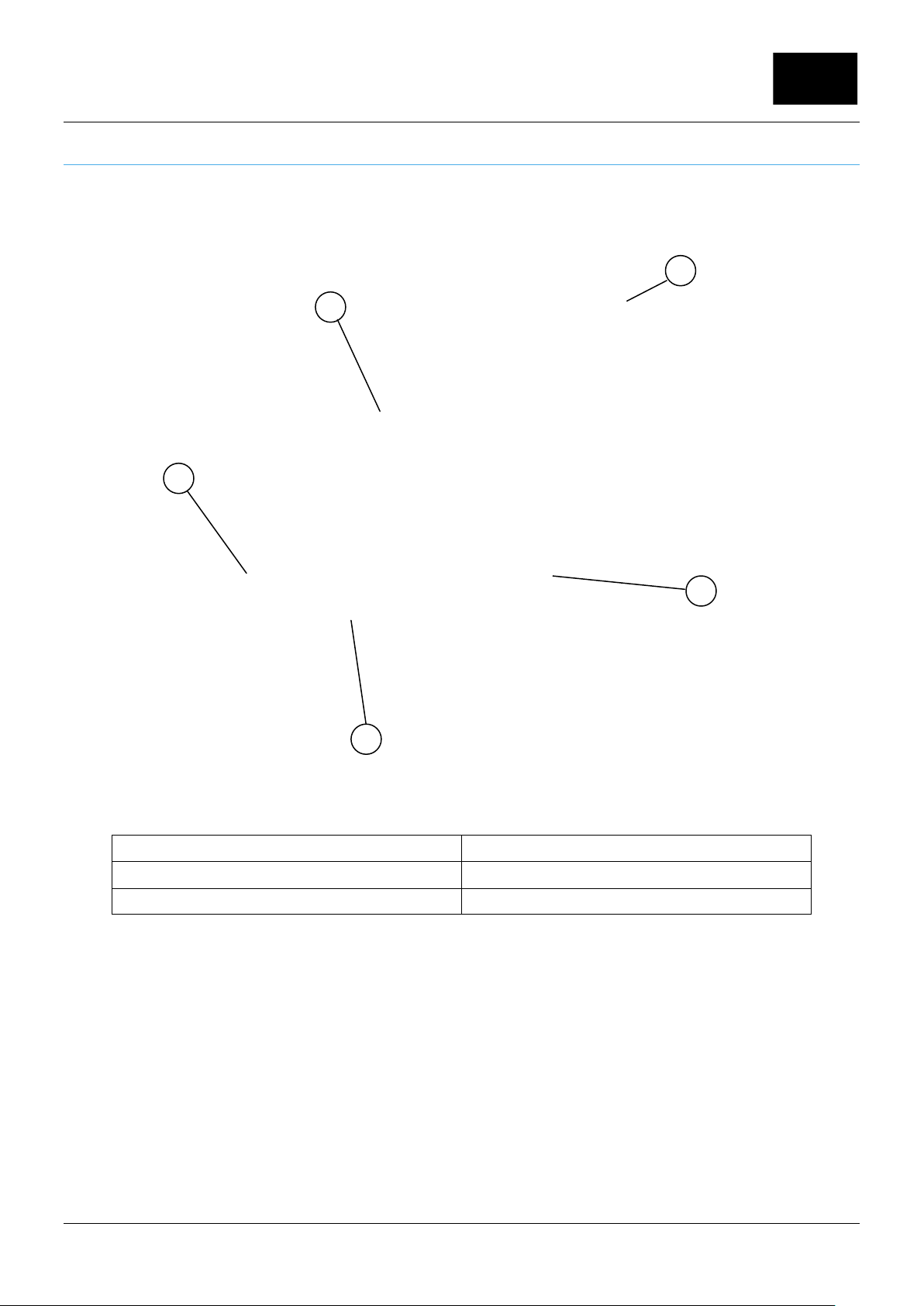
2.2 Product overview
The RAVEN-EYE
designed to withstand submersion during surcharge conditions. Optional level sensors provide the UNI-TRANS
monitor with the water level m easur em ent during normal operation.
®
sensor measures the flow velocity in open channels using radar technology. The unit is
2
4
3
1 RAVEN-EYE® Sensor 4 Mounting hardware (here: rotative handle)
2 Sensor cable 4 Level sensor mounting hardware
3 Level sensor
5
Figure 1: System
1
overview
- 7 -

Rue J.H. Cool 19a | B-4840 Welkenraedt | BELGIUM
Tel. : +32 (0)87 899 799 | Fax : +32 (0)87 899 790
E-mail : info@flow-tronic.com | www.flow-tronic.com
2.2.1 Theory of operation
The RAVEN-EYE® se nsor is mounted above an ope n channel of water and measures the surf ace velocity. The
depth from water is meas ured b y an opt io nal ass oc iate d le vel se nsor . The two measurements are us ed to c alculate
the flow rate using the cont inuity equation. The RAVEN-EYE
®
c onverts the surf ace velocity to aver age velocity b y
analyzing surfac e velocity dist ribution usin g a self-le arning tech nology that do esn’t require t heoretical m odules nor
site calibration. Then the water level and pipe size is converted to the fluid area. Multiplication of fluid area by
average velocity to obtain the flow rate.
Surface velocity measurement
The surface velocit y of the water is m easur ed using r adar tec hnol og y. A radar be am is transm itted f rom the sens or
to the water surface at the center of the channel. A portion of the signal is reflected back at a slightly different
frequency. The diff er enc e in frequency, known as the D opp ler f r eque ncy, is directly proportio na l to the s pee d of t he
flow. Proprietary P atent P endi ng ve locit y meas urem ent algor ithm s ar e then us ed t o calcu late th e aver age s peed of
the flow stream.
Note: The radar velocity sensor does not operate under surcharge conditions.
Level measurement
The water level is m easured using an ultrasonic pulse echo sensor. Two models are availab le, a standard range
1,75 m and a long range 5,75 m sensor. The sensors c an be attached to the RAVEN-EYE
®
sensor body using
specific mounting hardware. For both sens ors a sound pulse is s en t to th e wat er surface and a portio n of th e s igna l
is returned to the sens or. The trans it time to the surf ace and back is used to cal culate the distanc e from the water
surface to the sensor. The pipe diameter and sensor offset are used to convert the distance to water depth.
External 4-20 mA level se nsors from other m anufacturers can be used to be connected t o the UNI-TRANS or any
other PLC or logger.
Flow calculations
The velocity and d epth measurem ents are used with the channel shape and its dimensions to determ ine the flow
rate. The flow rate is calculated from the continuity equation (1):
(1) Flow rate = Average velocity × Area
where
Flow rate = volume of liquid that passes the sensor per unit time (e.g. 300 litres per second)
Average velocity = average velocit y of the liquid, calculated using surface vel ocity measurements
and patent pending measurements algorithms
Area = cross-sectional area of the liquid in the channel, calculated using the c hannel
dimensions and depth measurement.
- 8 -

Rue J.H. Cool 19a | B-4840 Welkenraedt | BELGIUM
Tel. : +32 (0)87 899 799 | Fax : +32 (0)87 899 790
E-mail : info@flow-tronic.com | www.flow-tronic.com
3 Installation
3.1 Unpack the instrument
Before opening the shiping boxes, check them for any visible outside damage, and report the damages
immediately.
Carefully unpack the RAVEN-EYE
damage. If an item is missing or damaged, please contact the manuf acturer or local agent (ref er to section 7 on
page- 28 -)
List of standard delivered items:
1. RAVEN-EYE
®
Sensor
2. Cable at specified length
3. Installation & operation manual
4. Extended warranty formular
5. USB communication cable (optional)
®
and its accessories from the shipping carton and inspect for any visible
6. Standrd range or long range level sensor (optional)
7. Permanent or one-time entry sensor mounting hardware (optional)
8. Mounting hardware for ultrasonic standard range or long range sensor (optional)
- 9 -
 Loading...