

Page 1
microLinK
Temperature Compensating Linearizing Pickoff
CANbus Implementation Manual
TM-100823, Rev A
Page 2

TM-100823, Rev A
microLinK CANbus Implementation Manual
Page 2
Thank you for selecting a Flow Technology, Inc. product for your flow measurement
application.
Virtually every major commercial, government, and scientific organization is making use of our
products, expertise and extensive technical support. This is a culmination of years of
refinement in our flow meter and calibrator designs, which has resulted in the technological
leadership in the flow measurements field that we enjoy.
We are proud of our quality products, our courteous service and welcome you, as a valued
customer, to our growing family.
Flow Technology Inc.
8930 South Beck Ave
Suite #107
Tempe, AZ 85284
Tel: +1 480 240 3400
Fax: +1 480 240 3401
www.ftimeters.com
SF-100828 Rev A
Page 3

TM-100823, Rev A
microLinK CANbus Implementation Manual
Page 3
DATE
REVISION
ECO NUMBER
APPROVAL
11/12/2012
A
22345
J. BLASIUS
The specifications contained in this manual are subject to change
without notice and any user of these specifications should verify from
the manufacturer that the specifications are currently in effect.
Otherwise, the manufacturer assumes no responsibility for the use of
specifications, which have been changed, and are no longer in effect.
TM-100823 REVISIONS
PUBLISHED BY FLOW TECHNOLOGY, INC. – November 2012
SF-100828 Rev A
Page 4

TM-100823, Rev A
microLinK CANbus Implementation Manual
Page 4
WARRANTY
Limited Warranty
Seller warrants that goods delivered hereunder will at delivery be free from defects in materials and workmanship
and will conform to seller's operating specifications. Seller makes no other warranties, express or implied, and
specifically makes NO WARRANTY OF MERCHANTABILITY OR FITNESS FOR A PARTICULAR PURPOSE.
Limitation of Liability
Seller's obligation under the warranty shall be limited to replacing or repairing at Seller's option, the defective
goods within twelve (12) months from the date of shipment, or eighteen (18) months from the date of shipment
for destination outside of the United States, provided that Buyer gives Seller proper notice of any defect or failure
and satisfactory proof thereof. Defective goods must be returned to Seller's plant or to a designated Seller's
service center for inspection. Buyer will prepay all freight charges to return any products to Seller's plant, or other
facility designated by Seller. Seller will deliver replacements for defective goods to Buyer freight prepaid. The
warranty on said replacements shall be limited to the unexpired portion of the original warranty. Goods returned
to Seller for which Seller provides replacement under the above warranty shall become the property of the Seller.
The limited warranty does not apply to failures caused by mishandling or misapplication. Seller's warranty
obligations shall not apply to any goods that (a) are normally consumed in operation or (b) have a normal life
inherently shorter than the warranty period stated herein. In the event that goods are altered or repaired by the
Buyer without prior written approval by the Seller, all warranties are void. Equipment and accessories not
manufactured by Seller are warranted only to the extent of and by the original manufacturer's warranty. Repair or
replacement goods furnished pursuant to the above warranty shall remain under warranty only for the unexpired
portion of the original warranty period.
Should Seller fail to manufacture or deliver goods other than standard products appearing in Seller's catalog,
Seller's exclusive liability and Buyer's exclusive remedy shall be release of the Buyer from the obligation to pay
purchase price therefore.
THE FORGOING WARRANTIES ARE IN LIEU OF ALL OTHER WARRANTIES WHETHER ORAL, WRITTEN, EXPRESSED,
IMPLIED OR STATUTORY. IMPLIED WARRANTIES OF FITNESS AND MERCHANTABILITY SHALL NOT APPLY SELLER'S
WARRANTY OBLIGATIONS AND BUYER'S REMEDIES THEREUNDER (EXCEPT AS TO TITLE) ARE SOLELY AND
EXCLUSIVELY AS STATED HEREIN. IN NO CASE WILL SELLER BE LIABLE FOR SPECIAL, INCIDENTAL OR
CONSEQUENTIAL DAMAGE.
The total liability of Seller (including its subcontractors) on any claim whether in contract, tort (including
negligence whether sole or concurrent) or otherwise, arising out of or connected with, or resulting from the
manufacture, sales, delivery, resale, repair, replacement or use of any goods or the furnishing of any service
hereunder shall not exceed the price allocable to the product or service or part thereof which gives rise to the
claim.
SF-100828 Rev A
Page 5

TM-100823, Rev A
microLinK CANbus Implementation Manual
Page 5
TABLE OF CONTENTS
1 INTRODUCTION ................................................................................................................... 7
1.1 Scope ............................................................................................................................. 7
1.2 Reference Documentation ............................................................................................ 7
2 INSTALLATION ..................................................................................................................... 8
2.1 Mechanical Installation of the microLinK pickoff to the flow meter ............................ 8
2.2 Electrical Installation ..................................................................................................... 8
3 CANOPEN INFORMATION ................................................................................................. 10
3.1 Device Profile .............................................................................................................. 10
3.2 Service Data Objects (SDO) Communication .............................................................. 10
3.3 Process Data Objects (PDO) Communication ............................................................. 10
3.4 Run Levels ................................................................................................................... 10
3.4.1 Changing run levels ............................................................................................... 12
3.5 Object Dictionary ........................................................................................................ 12
3.5.1 Object 0x1000 – Device Type ................................................................................ 12
3.5.2 Object 0x1001 – Error Register ............................................................................. 12
3.5.3 Object 0x1002 – Manufacturer Status Register ................................................... 13
3.5.4 Object 0x1003 – Pre-Defined Error Field .............................................................. 13
3.5.5 Object 0x1008 – Manufacturer Device Name ...................................................... 14
3.5.6 Object 0x1009 – Manufacturer Hardware Version .............................................. 14
3.5.7 Object 0x100A – Manufacturer Software Version................................................ 15
3.5.8 Object 0x1017 – Producer Heartbeat Time .......................................................... 15
3.5.9 Object 0x1018 – Identity Object ........................................................................... 15
3.5.10 Object 0x1800 – Transmit PDO Communication Parameter 1 ............................. 16
3.5.11 Object 0x1801 – Transmit PDO Communication Parameter 2 ............................. 17
3.5.12 Object 0x1A00 – TPDO Mapping Parameter 1 ..................................................... 18
3.5.13 Object 0x1A01 – TPDO Mapping Parameter 2 ..................................................... 18
3.5.14 Object 0x2010 – Flow Totals ................................................................................. 19
3.5.15 Object 0x2011 – Flow Rates .................................................................................. 20
3.5.16 Object 0x2012 – Raw Frequency .......................................................................... 20
3.5.17 Object 0x2013 – Live Temperature....................................................................... 20
3.5.18 Object 0x2021 – Flow Constants .......................................................................... 21
3.5.19 Object 0x2022 – Frequency Information .............................................................. 21
3.5.20 Object 0x2023 – Customer Information ............................................................... 23
3.5.21 Object 0x2024 – Model Numbers ......................................................................... 24
3.5.22 Object 0x2025 – Serial Numbers .......................................................................... 25
3.5.23 Object 0x2026 – Programming and Calibration Information ............................... 26
3.5.24 Object 0x2030 – Curve Data ................................................................................. 27
3.5.25 Object 0x2040 – Density Data .............................................................................. 27
3.5.26 Object 0x2041 – Viscosity Data ............................................................................ 29
3.5.27 Object 0x2042 – Fluids .......................................................................................... 31
3.5.28 Object 0x2050 – Density ....................................................................................... 32
SF-100828 Rev A
Page 6

TM-100823, Rev A
microLinK CANbus Implementation Manual
Page 6
3.5.29 Object 0x2051 – Viscosity ..................................................................................... 32
3.5.30 Object 0x2052 – COE ............................................................................................ 32
3.5.31 Object 0x2053 – Temperature Correction ............................................................ 32
3.5.32 Object 0x2054 – Calibration Temperature ........................................................... 33
3.5.33 Object 0x2055 –Temperature Source ................................................................... 33
3.5.34 Object 0x2057 – Fault Temperature ..................................................................... 34
3.5.35 Object 0x2060 – Units ........................................................................................... 34
3.5.36 Object 0x20FF – Boot Load Entry .......................................................................... 36
3.5.37 Object 0x2106 – Power On Counter ..................................................................... 36
3.5.38 Object 0x2107 – Run Level.................................................................................... 36
3.5.39 Object 0x2108 – CANbus Active COM Parameters ............................................... 37
3.5.40 Object 0x2109 – CANbus Bootup COM Parameters ............................................. 37
APPENDIX A MODEL NUMBER BREAK DOWN ........................................................................... 39
LIST OF FIGURES
Figure 1 – MS Connector Pinout ..................................................................................................... 8
Figure 2 – Flying Leads Wire Designators ....................................................................................... 9
LIST OF TABLES
Table 1 - Run Level Write Permissions .......................................................................................... 11
Table 2 - Error Register Bits (from CiA 301) ................................................................................. 13
Table 3 – Product Codes ............................................................................................................... 15
SF-100828 Rev A
Page 7

TM-100823, Rev A
microLinK CANbus Implementation Manual
Page 7
1 INTRODUCTION
1.1 Scope
This manual provides information and guidance for personnel responsible for using the
microLinK pickoff in a CANbus environment. For general purpose information regarding the
microLinK product, please consult Flow Technology manual TM-100736
1.2 Reference Documentation
This manual is not intended to be an all-inclusive CAN resource; it provides information
that is unique to the microLinK product. For more detailed information regarding CAN
communications and protocols, please consult the following documents.
CiA 102: CAN Physical Layer for Industrial Applications
CiA 301: CANopen Application layer and communication profile
CiA 303-1: CANopen Recommendation - Cabling and Connector Pin Assignment
CiA 306: CANopen Electronic data sheet specification
Additional Resources:
CAN in Automation (CiA) http://www.can-cia.org/
http://www.canopen.us/
SF-100828 Rev A
Page 8
TM-100823, Rev A
microLinK CANbus Implementation Manual
Page 8
2 INSTALLATION
2.1 Mechanical Installation of the microLinK pickoff to the flow meter
The pickoff should bottom in the well of the flow meter housing but only be finger
tightened to approximately 4 lb-in (0.5 N-m) max to prevent distortion of the coil housing.
The pickoff is secured in position by tightening the lock nut to approximately 25 lb-in (2.8
N-m). The pickoff can be removed by loosening the hex lock nut and unscrewing the
pickoff from the housing.
2.2 Electrical Installation
This section provides the professional installer with information for connecting the
microLinK to the user's system.
WARNING:
Verify that the power is off before connecting or servicing!
The connecting cable between the pickoff and the electronic instrumentation should use
22-28 AWG conductors. Shielded and twisted pairs are recommended for CANbus
installations. The cable should not be installed in a conduit or tray containing power lines,
or close to strong electromagnetic sources such as electric lines, electric motors,
transformers, welding machines, or high voltage lines. These sources may induce
transient electrical noise in the coil and cause false readings.
Since the Linearized Frequency and the Raw Frequency outputs both output pulse signals,
these signals can couple or crosstalk between wires. It is recommended that these wires
not be run together for more than 10 feet to avoid problems with crosstalk. Since the
Raw frequency is primarily used for diagnostics, it is recommended that this wire not be
attached to the connector wiring except when diagnostics are needed.
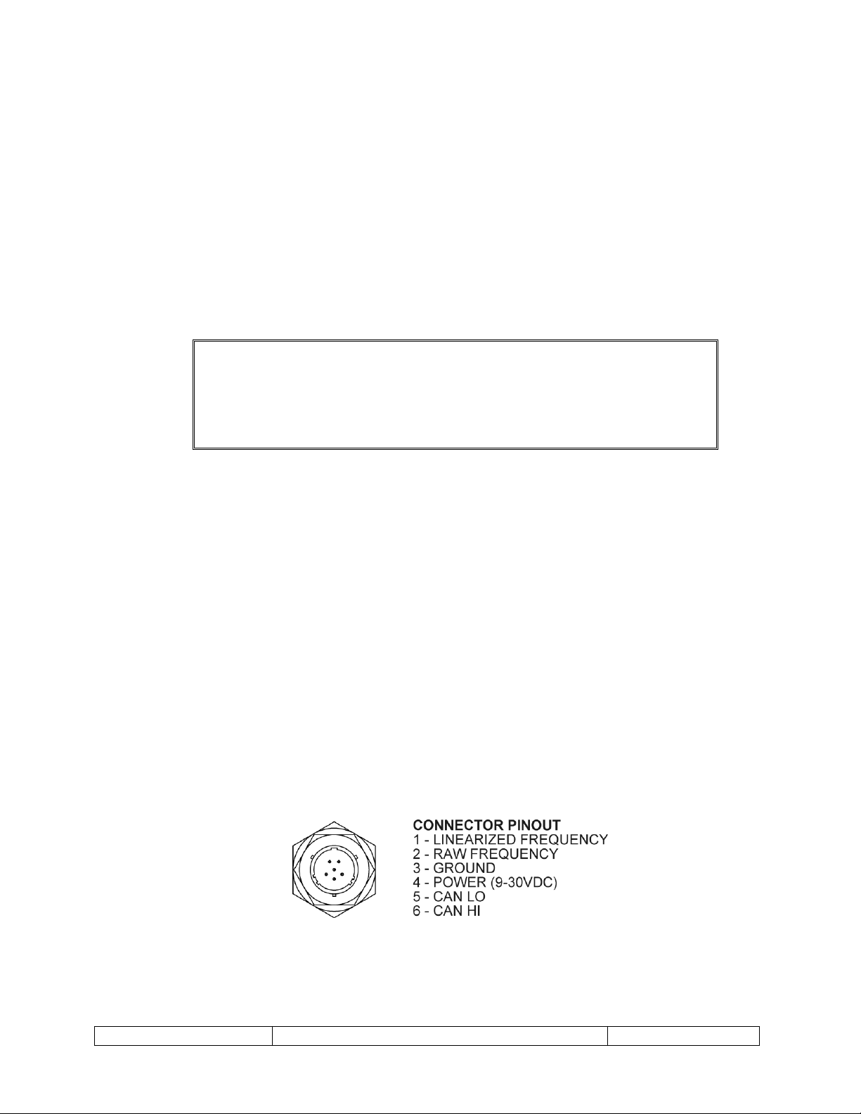
The connector pinout is shown in below Figure 1. The connector on the pickoff is a
commercial equivalent of MS27478Y8E35P. For package options “-5” and “-6” (flying
leads) see Figure 2.
SF-100828 Rev A
Figure 1 – MS Connector Pinout
Page 9

TM-100823, Rev A
microLinK CANbus Implementation Manual
Page 9
Figure 2 – Flying Leads Wire Designators
SF-100828 Rev A
Page 10

TM-100823, Rev A
microLinK CANbus Implementation Manual
Page 10
3 CANOPEN INFORMATION
3.1 Device Profile
The microLinK product follows the basic device profile specified in CiA 301. Additional
objects unique to the product are discussed in section 3.5. All objects are listed in EDS file
82-100951-xx.eds, where xx is the major revision number listed in object 0x1018sub3. For
example, if the major revision number is 1, then xx will be 01. Be sure that the EDS file
matches the microLinK revision.
3.2 Service Data Objects (SDO) Communication
Communication via Service Data Objects provides access to the objects listed in the
device dictionary. All of the objects listed may be queried and will respond with the data
stored in the object. Some of these objects are read only, some are read/write, and some
will respond as read only until the proper password is written to the Bootloader Object
(0x20FF), then are read/write.
The microLinK pickoff meets the requirements of the CANopen CiA 301 Application layer
and communication profile specification for SDOs. Please refer to this document for more
information on Service Data Objects.
3.3 Process Data Objects (PDO) Communication
Real time data transfer is provided via Process Data Objects. PDOs provide a lower
overhead communication method. The microLinK pickoff provides two PDO
transmissions, each of which contains two operating parameters. The first PDO provides
the volume rate and mass rate data. The second PDO provides raw frequency and
temperature data. The microLinK pickoff only supports timer-driven asynchronous
transmit PDOs.
The microLinK pickoff meets the requirements of the CANopen CiA 301 Application layer
and communication profile specification for PDOs. Please refer to this document for more
information on Process Data Objects.
3.4 Run Levels
The microLinK uses three run levels to protect data from accidental modification. SDO
data is readable at any run level, but may only be written if the current run level supports
writing for that object. The run level privileges are incremental, i.e. any object that is
writable at run level 1 is also writable at run level 2.
The run level scheme is intended to prevent accidental modification to SDO data. It is not
intended as a security scheme to prevent malicious changes to the SDO data.
Run level 0 is the default run level. The microLinK is set on power up or reset to this run
level. This run level protects most objects from accidental writing.
Run level 1 is user level. Certain objects that may need to be changed during operation
can be written to at this run level.
SF-100828 Rev A
Page 11

TM-100823, Rev A
microLinK CANbus Implementation Manual
Page 11
Description
Index
Run Level
0 1 2
Customer Name
0x2023sub1
X X X
Job Number
0x2023sub2
X X X
PO Number
0x2023sub3
X X X
Meter Model Number
0x2024sub1
X X X
Meter Tag Number
0x2024sub2
X X X
Electronic Model Number
0x2024sub3
X X X
Electronic Tag Number
0x2024sub4
X X X
Bootloader Object
0x20FF
X X X
Producer Heartbeat Time
0x2017
X X
PDO Inhibit Times
0x1800sub3,
0x1801sub3
X X
PDO Event Timers
0x1800sub5,
0x1801sub5
X X
Totalizers
0x2010sub1-4
X X
Frequency Information
Low Frequency Cutoff
Frequency Averaging Factor
Scaling Data
Volumetric or Mass Flow
Averaging Limit
0x2022sub1
0x2022sub4
0x2022sub5-8
0x2022sub9
0x2022subA
X X
Active Fluid
0x2042sub1
X X
Fluid Names
0x2042sub2-4
X X
Temperature Correction
0x2053
X X
External Temperature Control
0x2055
X X
Baud Rate
0x2109sub2
X X
Node ID
0x2109sub1
X X
Timebase
0x2021sub2
X
Meter Overspeed Frequency
0x2022sub2
X
Meter Serial Number
0x2025sub1
X
Electronic Serial Number
0x2025sub2
X
Programming Date
0x2026sub1
X
Technician Name
0x2026sub2
X
Calibration Curve Data (f/ curve)
0x2030
X
Fluid Viscosity Data
0x2041
X
Fluid Density Data
0x2040
X
COE
0x2052
X
Run level 2 is the pickoff configuration level. Objects such as calibration data that will not
be changed during normal operation are only writable at this run level.
Table 1 - Run Level Write Permissions
SF-100828 Rev A
Page 12

TM-100823, Rev A
microLinK CANbus Implementation Manual
Page 12
Description
Index
Run Level
0 1 2
Calibration Temperature
0x2054
X
Fault Temperature
0x2057
X
Data Units
0x2060
X
Index
0x1000
Object Name
Device Type
Data Type
UNSIGNED32
Access Type
RO | RO | RO
3.4.1 Changing run levels
The run level is changed by writing a password to object 0x20FF. The run level change is
persistent until another password is written to object 0x20FF or until the pickoff is reset.
Object 0x20FF is used for other functions such as putting the pickoff into bootloader
mode. This object is used for some factory-only functions and writing values other than
the specified passwords may cause erroneous operation of the pickoff.
Run Level 0 password = 0x0FF
Run Level 1 password = 0xC5EF
Run Level 2 password = 0xACC355
3.5 Object Dictionary
This section lists objects available for configuration and operation of the microLinK
pickoff. The read-write status for each object is shown as three choices. These choices are
listed in the following order run level 0 | run level 1 | run level 2. For example the
Producer Heartbeat Time in object 0x1017 shows RO | RW | RW for the Access
Type. This means that run level 0 has read-only permissions while run levels 1 and 2 have
read-write permissions.
3.5.1 Object 0x1000 – Device Type
This object specifies the device profile in effect for the unit. The microLinK pickoff does
not follow a standardized device profile and therefore is zero.
3.5.2 Object 0x1001 – Error Register
This object holds the errors for the device. The following error bits are supported by the
microLinK pickoff.
SF-100828 Rev A
Page 13

TM-100823, Rev A
microLinK CANbus Implementation Manual
Page 13
Table 2 - Error Register Bits (from CiA 301)
Bit
Meaning
Supported by
microLinK
0
Generic
Yes 1 Current
No 2 Voltage
No 3 Temperature
No 4 Communication Error
Yes 5 Device Profile Specific
No 6 Reserved (Always 0)
Always 0
7
Manufacturer Specific
Yes
Index
0x1001
Object Name
Error Register
Data Type
UNSIGNED8
Access Type
RO | RO | RO
Index
0x1002
Object Name
Manufacturer Status Register
Data Type
UNSIGNED32
Access Type
RO | RO | RO
If a bit is set to 1, the specified error has occurred.
The generic error is signaled at any error situation. The manufacturer specific error is set
with a:
Temperature sensor error
Viscosity error
Density error
3.5.3 Object 0x1002 – Manufacturer Status Register
This object will always return a 0x00.
Use of this register is reserved for later versions of firmware.
3.5.4 Object 0x1003 – Pre-Defined Error Field
This object contains a history of the errors that have occurred. Subindex 0 contains the
number of errors contained in the history. Writing to subindex 0 clears the history.
When an error occurs, information about the error is placed in the history in subindex 1,
and subindex 0 is incremented. When error information is placed into subindex 1, the
information that was in subindex 1 is shifted into subindex 2, the information that was
in subindex 2 is shifted into subindex 3, etc. If the error is cleared, the cleared error
information is placed in the history in subindex 1, and the subindexes are shifted the
same as if a new error had occurred.
SF-100828 Rev A
Page 14

TM-100823, Rev A
microLinK CANbus Implementation Manual
Page 14
The error history can provide additional information about an error. The following
Index
0x1003
Object Name
Pre-Defined Error Field
Data Type
ARRAY
Subindex
0
Object Name
Number of Errors
Data Type
UNSIGNED8
Access Type
RW | RW | RW
Subindex
8
Object Name
Error Field 8
Data Type
UNSIGNED32
Access Type
RO | RO | RO
Index
0x1008
Object Name
Manufacturer Device Name
Data Type
VISIBLE_STRING
Access Type
RO | RO | RO
Index
0x1009
Object Name
Manufacturer Device Name
Data Type
VISIBLE_STRING
Access Type
RO | RO | RO
information is added to the error history when a manufacturer specific error occurs.
0x00011001 Invalid Viscosity
0x00021001 Invalid Density
0x03000000 Invalid Viscosity or Density error cleared
0x????1002 Temperature Sensor Error (Where ???? is additional information
on the sensor fault)
0x03010000 Temperature Sensor Error cleared
0x00??1005 Watchdog Reset (Where ?? is additional startup information)
0x03040000 Watchdog Reset error cleared
…
3.5.5 Object 0x1008 – Manufacturer Device Name
This object holds the device name. For the microLinK product line, the entry is
microLinK.
3.5.6 Object 0x1009 – Manufacturer Hardware Version
This object holds the revision level of the main circuit board inside the pickoff. This value
is also available in object 0x2025sub4.
SF-100828 Rev A
Page 15

TM-100823, Rev A
microLinK CANbus Implementation Manual
Page 15
3.5.7 Object 0x100A – Manufacturer Software Version
Index
0x100A
Object Name
Manufacturer Software Version
Data Type
VISIBLE_STRING
Access Type
RO | RO | RO
Index
0x1017
Object Name
Producer Heartbeat Time
Data Type
UNSIGNED16
Access Type
RO | RW | RW
Model Number
Product Code
ULN-C-1-00-1
100721101
ULN-C-1-00-5
100721102
ULN-C-1-00-6
100721103
Index
0x1018
Object Name
Identity Object
Object Type
Record
This object holds the version of the software in the pickoff.
3.5.8 Object 0x1017 – Producer Heartbeat Time
This object holds the cycle time in milliseconds of the heartbeat generated by the
microLinK. Fractional values are not allowed.
3.5.9 Object 0x1018 – Identity Object
This object holds generic information about the device.
Vendor ID is the unique value of 0x032B, allocated to Flow Technology by the CiA
organization.
Product Code is the code assigned to the product from Flow Technology. This value
is a number representing the model number of the pickoff without the dashes. Table 3
below lists the product codes for the different model numbers.
Table 3 – Product Codes
Revision Number is a revision number for the microLinK product. It consists of a 16bit major revision and a 16-bit minor revision. If the CANopen behavior (EDS) changes,
the major revision is incremented. All other changes will cause the minor revision to
increment.
Serial Number is the serial number of the circuit board inside the pickoff. This is the
same value that appears in object 0x2025sub3.
SF-100828 Rev A
Page 16

TM-100823, Rev A
microLinK CANbus Implementation Manual
Page 16
Subindex
1
Object Name
Vendor ID
Data Type
UNSIGNED32
Access Type
RO | RO | RO
Subindex
2
Object Name
Product Code
Data Type
UNSIGNED32
Access Type
RO | RO | RO
Subindex
3
Object Name
Revision Number
Data Type
UNSIGNED32
Access Type
RO | RO | RO
Subindex
4
Object Name
Serial Number
Data Type
UNSIGNED32
Access Type
RO | RO | RO
Index
0x1800
Object Name
Transmit PDO Communication
Parameter 1
Object Type
Record
Subindex
1
Object Name
COB-ID
Data Type
UNSIGNED32
Access Type
RO | RO | RO
Subindex
2
Object Name
Transmission Type
Data Type
UNSIGNED8
Access Type
RO | RO | RO
3.5.10 Object 0x1800 – Transmit PDO Communication Parameter 1
This object holds information about the PDOs the device is able to transmit.
COB-ID is the COB-ID for the data being transmitted.
Transmission Type defines the transmission type of the PDO. Only Transmission
Type 254 is supported.
Inhibit Time is a minimum interval for PDO transmission. The value is defined as a
multiple of 100μs.
Event Timer is the number of milliseconds between transmissions. A value of 0 will
turn off the PDO transmissions.
SF-100828 Rev A
Page 17

TM-100823, Rev A
microLinK CANbus Implementation Manual
Page 17
Subindex
3
Object Name
Inhibit Time
Data Type
UNSIGNED16
Access Type
RO | RW | RW
Subindex
4
Object Name
Reserved
Data Type
N/A
Access Type
N/A
Subindex
5
Object Name
Event Timer
Data Type
UNSIGNED16
Access Type
RO | RW | RW
Index
0x1801
Object Name
Transmit PDO Communication
Parameter 2
Object Type
Record
Subindex
1
Object Name
COB-ID
Data Type
UNSIGNED32
Access Type
RO | RO | RO
Subindex
2
Object Name
Transmission Type
Data Type
UNSIGNED8
Access Type
RO | RO | RO
3.5.11 Object 0x1801 – Transmit PDO Communication Parameter 2
This object holds information about the PDOs the device is able to transmit. See the
previous section.
COB-ID is the object number for the data being transmitted.
Transmission Type defines the transmission/reception character of the PDO.
Inhibit Time is a minimum interval for PDO transmission. The value is defined as a
multiple of 100μs. The value is not allowed to be changed while the PDO exists.
Event Timer is the number of milliseconds between transmissions. A value of 0 will
turn off the PDO transmissions.
SF-100828 Rev A
Page 18

TM-100823, Rev A
microLinK CANbus Implementation Manual
Page 18
Subindex
3
Object Name
Inhibit Time
Data Type
UNSIGNED16
Access Type
RO | RW | RW
Subindex
4
Object Name
Reserved
Data Type
N/A
Access Type
N/A
Subindex
5
Object Name
Event Timer
Data Type
UNSIGNED16
Access Type
RO | RW | RW
Index
0x1A01
Object Name
TPDO Mapping Parameter 1
Object Type
Record
Subindex
1
Object Name
VolumeRatePDO
Data Type
UNSIGNED32
Access Type
RO | RO | RO
Subindex
2
Object Name
MassRatePDO
Data Type
UNSIGNED32
Access Type
RO | RO | RO
Index
0x1A00
Object Name
TPDO Mapping Parameter 2
Object Type
Record
Subindex
1
Object Name
RawFrequencyPDO
Data Type
UNSIGNED32
Access Type
RO | RO | RO
3.5.12 Object 0x1A00 – TPDO Mapping Parameter 1
This object holds the mapping for the PDOs the device is able to transmit.
3.5.13 Object 0x1A01 – TPDO Mapping Parameter 2
This object holds the mapping for the PDOs the device is able to transmit.
SF-100828 Rev A
Page 19

TM-100823, Rev A
microLinK CANbus Implementation Manual
Page 19
Subindex
2
Object Name
LiveTemperaturePDO
Data Type
UNSIGNED32
Access Type
RO | RO | RO
Index
0x2010
Object Name
Flow Totals
Object Type
Array
Subindex
1
Object Name
Volume Total 1
Data Type
REAL32
Access Type
RO | RW | RW
Subindex
2
Object Name
Volume Total 2
Data Type
REAL32
Access Type
RO | RW | RW
Subindex
3
Object Name
Mass Total 1
Data Type
REAL32
Access Type
RO | RW | RW
3.5.14 Object 0x2010 – Flow Totals
This object holds the total amount of volume and mass that has passed through the flow
meter since the last reset of the total. Each total can be individually reset by writing a
zero to that total. The total can also be preset to a specific value by writing the desired
preset value to the total. The total’s value is stored in EEPROM when power is removed
from the microLinK. Note that re-programming the unit with Visual LinK will reset all
totals to zero.
Volume Total 1 is the total volume of fluid since the last time the totalizers were
last reset. See 0x2060 for more information regarding unit identifiers.
Volume Total 2 is the total volume of fluid since the last time the totalizers were
last reset. See 0x2060 for more information regarding unit identifiers.
Mass Total 1 is the total mass of fluid since the last time the totalizers were last
reset. See 0x2060 for more information regarding unit identifiers.
Mass Total 2 is the total mass of fluid since the last time the totalizers were last
reset. See 0x2060 for more information regarding unit identifiers.
SF-100828 Rev A
Page 20

TM-100823, Rev A
microLinK CANbus Implementation Manual
Page 20
Subindex
4
Object Name
Mass Total 2
Data Type
REAL32
Access Type
RO | RW | RW
Index
0x2011
Object Name
Flow Rates
Object Type
Array
Subindex
1
Object Name
Volume Rate
Data Type
REAL32
Access Type
RO | RO | RO
Subindex
2
Object Name
Mass Rate
Data Type
REAL32
Access Type
RO | RO | RO
Index
0x2012
Object Name
Raw Frequency
Data Type
REAL32
Access Type
RO | RO | RO
3.5.15 Object 0x2011 – Flow Rates
This object holds the current flow rate values. See TM-100736 for more information on
how the flow rate values are calculated.
Volume Rate is the current volumetric flow rate. See 0x2060 for more information
regarding unit identifiers.
Mass Rate is the current mass flow rate. See 0x2060 for more information regarding
unit identifiers.
3.5.16 Object 0x2012 – Raw Frequency
This object holds the current raw flow meter frequency. This is a measured value.
3.5.17 Object 0x2013 – Live Temperature
This object holds the current fluid temperature. Note this value will either be from the
internal temperature sensor (measured value) or from object 0x2055sub2 depending on
the value of 0x2055sub1. See 0x2060 for more information regarding unit identifiers.
SF-100828 Rev A
Page 21

TM-100823, Rev A
microLinK CANbus Implementation Manual
Page 21
Index
0x2013
Object Name
Live Temperature
Data Type
REAL32
Access Type
RO | RO | RO
Index
0x2021
Object Name
Flow Constants
Object Type
Array
Subindex
1
Object Name
Reserved
Data Type
N/A
Access Type
N/A
Subindex
2
Object Name
TimeBase
Data Type
UNSIGNED32
Access Type
RO | RO | RW
Subindex
3
Object Name
Reserved
Data Type
N/A
Access Type
N/A
3.5.18 Object 0x2021 – Flow Constants
This object holds the information for the conversion of time units.
TimeBase value is the number of seconds in the current time unit. For example if the
current time unit is minutes, TimeBase will be 60. For hours, TimeBase will be 3600.
3.5.19 Object 0x2022 – Frequency Information
This object holds various parameters associated with measuring the frequency of the
rotor and generating the linearized output frequency.
Low Freq Cutoff is the lowest raw frequency the microLinK will use. All raw
(measured) frequencies below this value will be considered zero.
Meter Overspeed Freq sets the maximum allowed raw frequency of the flow
meter. If the raw frequency goes above this value the value in 0x2022sub3 is
incremented by one. This is not a cutoff. If the frequency measured by the microLinK
goes above this value, the raw frequency used is the measured frequency.
Meter Overspeeds is a counter for the number of time the raw frequency has
exceeded the value in 0x2022sub2.
SF-100828 Rev A
Page 22

TM-100823, Rev A
microLinK CANbus Implementation Manual
Page 22
Averaging Factor is used to average the incoming raw frequency as shown below.
1
)*(
ctorveragingFaFrequencyA
dFrequencyNewMeasurectorveragingFaFrequencyAquencyAverageFre
quencyAverageFre
Index
0x2022
Object Name
Frequency Information
Object Type
Array
Subindex
1
Object Name
Low Freq Cutoff
Data Type
REAL32
Access Type
RO | RW | RW
The higher the value, the slower the microLinK’s response to frequency change is.
Permissible values are from 0 to 250. See TM-100736 for more information regarding
this object.
Note: Averaging Factor values from 251 to 254 are used for extreme averaging.
251: Averaging Factor = 500
252: Averaging Factor = 1000
253: Averaging Factor = 1500
254: Averaging Factor = 2000
Min Scaling Freq is the frequency which corresponds to the minimum flow rate.
Frequency by definition cannot be negative.
Min Rate is the flow rate which corresponds to the Min Scaling Freq.
Max Scaling Freq is the frequency which represents the maximum flow rate.
Max Rate is the flow rate corresponding to the Max Scaling Freq.
Volumetric or Mass Flow determines if the linearized output frequency
represents volume or mass flow. It is set to 1 for volumetric flow rate and 2 for mass
flow rate. A value of 0 turns the linearized frequency output off.
Average Limit is used to increase the response time with a high Averaging Factor. A
very high value effectively disables the average limit. A value of less than one disables
the averaging factor. If the new measured frequency is greater than the Average
Frequency multiplied by the Average Limit (or less than the Average Frequency divided
by the Average Limit), the new measured frequency is put directly into Average
Frequency. See TM-100736 for more information regarding the Average Limit.
SF-100828 Rev A
Page 23

TM-100823, Rev A
microLinK CANbus Implementation Manual
Page 23
Subindex
2
Object Name
Meter Overspeed Freq
Data Type
REAL32
Access Type
RO | RO | RW
Subindex
3
Object Name
Meter Overspeeds
Data Type
UNSIGNED16
Access Type
RO | RO | RO
Subindex
4
Object Name
Averaging Factor
Data Type
UNSIGNED8
Access Type
RO | RW | RW
Subindex
5
Object Name
Min Scaling Freq
Data Type
REAL32
Access Type
RO | RW | RW
Subindex
6
Object Name
Min Rate
Data Type
REAL32
Access Type
RO | RW | RW
Subindex
7
Object Name
Max Scaling Freq
Data Type
REAL32
Access Type
RO | RW | RW
Subindex
8
Object Name
Max Rate
Data Type
REAL32
Access Type
RO | RW | RW
Subindex
9
Object Name
Volumetric or Mass Flow
Data Type
UNSIGNED8
Access Type
RO | RW | RW
Subindex
A
Object Name
Average Limit
Data Type
REAL32
Access Type
RO | RW | RW
3.5.20 Object 0x2023 – Customer Information
This object holds various pieces of customer information.
SF-100828 Rev A
Page 24

TM-100823, Rev A
microLinK CANbus Implementation Manual
Page 24
Customer Name is the name of the customer for which the product was initially built.
Index
0x2023
Object Name
Customer Information
Object Type
Array
Subindex
1
Object Name
Customer Name
Data Type
VISIBLE_STRING
Access Type
RW | RW | RW
Subindex
2
Object Name
Job Number
Data Type
VISIBLE_STRING
Access Type
RW | RW | RW
Subindex
3
Object Name
PO Number
Data Type
VISIBLE_STRING
Access Type
RW | RW | RW
This field must contain 30 characters. If the name is shorter than 30, additional
characters (e.g. spaces or nulls) must be added to the end.
Job Number is the sales order number on which the product was initially built. This
field must contain 20 characters. If the name is shorter than 20, additional characters
(e.g. spaces or nulls) must be added to the end.
PO Number is the purchase order on which the product was initially built. This field
must contain 20 characters. If the name is shorter than 20, additional characters (e.g.
spaces or nulls) must be added to the end.
3.5.21 Object 0x2024 – Model Numbers
This object holds the various model numbers for the unit.
Meter Model Number is the model number of the mating flow meter. This field
must contain 18 characters. If the name is shorter than 18, additional characters (e.g.
spaces or nulls) must be added to the end.
Meter Tag Number is the customer tag number of the mating flow meter. This field
must contain 18 characters. If the name is shorter than 18, additional characters (e.g.
spaces or nulls) must be added to the end.
Electronic Model Number is the model number of the microLinK pickoff. This
field must contain 18 characters. If the name is shorter than 18, additional characters
(e.g. spaces or nulls) must be added to the end.
SF-100828 Rev A
Page 25

TM-100823, Rev A
microLinK CANbus Implementation Manual
Page 25
Electronic Tag Number is the customer tag number of the microLinK pickoff.
Index
0x2024
Object Name
Model Numbers
Object Type
Array
Subindex
1
Object Name
Meter Model Number
Data Type
VISIBLE_STRING
Access Type
RW | RW | RW
Subindex
2
Object Name
Meter Tag Number
Data Type
VISIBLE_STRING
Access Type
RW | RW | RW
Subindex
3
Object Name
Electronic Model Number
Data Type
VISIBLE_STRING
Access Type
RW | RW | RW
Subindex
4
Object Name
Electronic Tag Number
Data Type
VISIBLE_STRING
Access Type
RW | RW | RW
This field must contain 18 characters. If the name is shorter than 18, additional
characters (e.g. spaces or nulls) must be added to the end.
3.5.22 Object 0x2025 – Serial Numbers
This object holds the various serial numbers for the unit.
Meter Serial Number is the serial number of the mating flow meter. This field
must contain 12 characters. If the name is shorter than 12, additional characters (e.g.
spaces or nulls) must be added to the end.
Electronic Serial Number is the serial number of the microLinK pickoff. This
field must contain 12 characters. If the name is shorter than 12, additional characters
(e.g. spacesor nulls) must be added to the end.
Board Serial Number is the serial number of the circuit board inside the pickoff.
This is the same value that appears in object 0x1018sub4.
Hardware Version is the revision level of the circuit board inside the pickoff.
SF-100828 Rev A
Page 26

TM-100823, Rev A
microLinK CANbus Implementation Manual
Page 26
Index
0x2025
Object Name
Serial Numbers
Object Type
Array
Subindex
1
Object Name
Meter Serial Number
Data Type
VISIBLE_STRING
Access Type
RO | RO | RW
Subindex
2
Object Name
Electronic Serial Number
Data Type
VISIBLE_STRING
Access Type
RO | RO | RW
Subindex
3
Object Name
Board Serial Number
Data Type
UNSIGNED32
Access Type
RO | RO | RO
Subindex
4
Object Name
Hardware Version
Data Type
VISIBLE_STRING
Access Type
RO | RO | RO
Index
0x2026
Object Name
Programming Information
Object Type
Array
Subindex
1
Object Name
Programming Date
Data Type
UNSIGNED32
Access Type
RO | RO | RW
Subindex
2
Object Name
Technician Name
Data Type
VISIBLE_STRING
Access Type
RO | RO | RW
3.5.23 Object 0x2026 – Programming and Calibration Information
This object holds information about the last time the pickoff was programmed.
Programming Date is the last date the pickoff was last programmed with Visual
LinK. The format of the date is such that April 25, 2012 is written as 20120425.
Technician Name is the name of the technician who did the programming. This field
must contain 12 characters. If the name is shorter than 12, additional characters (e.g.
spaces or nulls) must be added to the end.
SF-100828 Rev A
Page 27

TM-100823, Rev A
microLinK CANbus Implementation Manual
Page 27
Index
0x2030
Object Name
Curve Data
Object Type
Array
Subindex
1
Object Name
Freq/Visc 1
Data Type
UNSIGNED32
Access Type
RO | RO | RW
Subindex
2
Object Name
Kf 1
Data Type
UNSIGNED32
Access Type
RO | RO | RW
Subindex
3B
Object Name
Freq/Visc 30
Data Type
UNSIGNED32
Access Type
RO | RO | RW
Subindex
3C
Object Name
Kf 30
Data Type
UNSIGNED32
Access Type
RO | RO | RW
3.5.24 Object 0x2030 – Curve Data
This object holds the composite curve data pairs for the flow meter. There are 30 data
pairs in the object. The pairs are in ascending order by frequency over viscosity. If less
than 30 pairs are available for use, the last pair must be repeated for the remainder of
the table.
Freq/Visc [1|2|3|…|30] is the value for frequency divided by viscosity. The
units for freq/visc are Hz/cSt.
Kf [1|2|3|…|30] is the value for the K-Factor. The units for K-Factor are pulses per
volume. See 0x2060 for more information regarding unit identifiers.
…
3.5.25 Object 0x2040 – Density Data
This object holds the fluid density data pairs for the three different fluids. There are 20
data pairs for each of the three fluids in the object. The pairs are in ascending order by
temperature. If less than 20 pairs are available for use, the last pair must be repeated
for the remainder of each portion of the table.
SF-100828 Rev A
Page 28

TM-100823, Rev A
microLinK CANbus Implementation Manual
Page 28
T[1|2|3|…|20] is the value for temperature. See 0x2060 for more information
Index
0x2040
Object Name
Density Data
Object Type
Array
Subindex
1
Object Name
T1 Fluid 1
Data Type
REAL32
Access Type
RO | RO | RW
Subindex
2
Object Name
D1 Fluid 1
Data Type
REAL32
Access Type
RO | RO | RW
Subindex
27
Object Name
T20 Fluid 1
Data Type
REAL32
Access Type
RO | RO | RW
Subindex
28
Object Name
D20 Fluid 1
Data Type
REAL32
Access Type
RO | RO | RW
Subindex
29
Object Name
T1 Fluid 2
Data Type
REAL32
Access Type
RO | RO | RW
Subindex
2A
Object Name
D1 Fluid 2
Data Type
REAL32
Access Type
RO | RO | RW
Subindex
4F
Object Name
T20 Fluid 2
Data Type
REAL32
Access Type
RO | RO | RW
regarding unit identifiers.
D[1|2|3|…|20] is the value for density. See 0x2060 for more information regarding
unit identifiers.
…
…
SF-100828 Rev A
Page 29

TM-100823, Rev A
microLinK CANbus Implementation Manual
Page 29
Subindex
50
Object Name
D20 Fluid 2
Data Type
REAL32
Access Type
RO | RO | RW
Subindex
51
Object Name
T1 Fluid 3
Data Type
REAL32
Access Type
RO | RO | RW
Subindex
52
Object Name
D1 Fluid 3
Data Type
REAL32
Access Type
RO | RO | RW
Subindex
77
Object Name
T20 Fluid 3
Data Type
REAL32
Access Type
RO | RO | RW
Subindex
78
Object Name
D20 Fluid 3
Data Type
REAL32
Access Type
RO | RO | RW
Index
0x2041
Object Name
Viscosity Data
Object Type
Array
Subindex
1
Object Name
T1 Fluid 1
Data Type
REAL32
Access Type
RO | RO | RW
…
3.5.26 Object 0x2041 – Viscosity Data
This object holds the fluid viscosity data pairs for the three different fluids. There are 20
data pairs for each of the three fluids in the object. The pairs are in ascending order by
temperature. If less than 20 pairs are available for use, the last pair must be repeated
for the remainder of each portion of the table.
T[1|2|3|…|20] is the value for temperature. See 0x2060 for more information
regarding unit identifiers.
v[1|2|3|…|20] is the value for viscosity in cSt.
SF-100828 Rev A
Page 30

TM-100823, Rev A
microLinK CANbus Implementation Manual
Page 30
Subindex
2
Object Name
v1 Fluid 1
Data Type
REAL32
Access Type
RO | RO | RW
Subindex
27
Object Name
T20 Fluid 1
Data Type
REAL32
Access Type
RO | RO | RW
Subindex
28
Object Name
v20 Fluid 1
Data Type
REAL32
Access Type
RO | RO | RW
Subindex
29
Object Name
T1 Fluid 2
Data Type
REAL32
Access Type
RO | RO | RW
Subindex
2A
Object Name
v1 Fluid 2
Data Type
REAL32
Access Type
RO | RO | RW
Subindex
4F
Object Name
T20 Fluid 2
Data Type
REAL32
Access Type
RO | RO | RW
Subindex
50
Object Name
v20 Fluid 2
Data Type
REAL32
Access Type
RO | RO | RW
Subindex
51
Object Name
T1 Fluid 3
Data Type
REAL32
Access Type
RO | RO | RW
Subindex
52
Object Name
v1 Fluid 3
Data Type
REAL32
Access Type
RO | RO | RW
…
…
SF-100828 Rev A
Page 31

TM-100823, Rev A
microLinK CANbus Implementation Manual
Page 31
Subindex
77
Object Name
T20 Fluid 3
Data Type
REAL32
Access Type
RO | RO | RW
Subindex
78
Object Name
v20 Fluid 3
Data Type
REAL32
Access Type
RO | RO | RW
Index
0x2042
Object Name
Fluids
Object Type
DEFSTRUCT
Subindex
1
Object Name
Active Fluid
Data Type
UNSIGNED8
Access Type
RO | RW | RW
Subindex
2
Object Name
Fluid 1 Name
Data Type
VISIBLE_STRING
Access Type
RO | RW | RW
Subindex
3
Object Name
Fluid 2 Name
Data Type
VISIBLE_STRING
Access Type
RO | RW | RW
Subindex
4
Object Name
Fluid 3 Name
Data Type
VISIBLE_STRING
Access Type
RO | RW | RW
…
3.5.27 Object 0x2042 – Fluids
This object holds the active fluid number and the names for the three fluids.
Active Fluid lists the fluid number that is active. Valid entries are 1, 2, or 3.
Fluid [1|2|3|] Name is the name of the fluid. This field must contain 12
characters. If the name is shorter than 12, additional characters (e.g. spaces or nulls)
must be added to the end. The name of the fluid is informational only and has no effect
on the operation of the microLinK.
SF-100828 Rev A
Page 32

TM-100823, Rev A
microLinK CANbus Implementation Manual
Page 32
3.5.28 Object 0x2050 – Density
Index
0x2050
Object Name
Density
Data Type
REAL32
Access Type
RO | RO | RO
Index
0x2051
Object Name
Density
Data Type
REAL32
Access Type
RO | RO | RO
Index
0x2052
Object Name
COE
Data Type
REAL32
Access Type
RO | RO | RW
Index
0x2042
Object Name
Temperature Correction
Object Type
DEFSTRUCT
This object holds the current density as calculated from the live temperature reading in
object 0x2013, the active fluid listed in 0x2042sub1, and the fluid temperature-density
data in 0x2040. See 0x2060 for more information regarding unit identifiers.
3.5.29 Object 0x2051 – Viscosity
This object holds the current viscosity as calculated from the live temperature reading in
object 0x2013, the active fluid listed in 0x2042sub1, and the fluid temperature-viscosity
data in 0x2041. The units for this value are cSt.
3.5.30 Object 0x2052 – COE
This object holds the coefficient of expansion for the flow meter housing material. The
units for this value are in./in./°F or m/m/°C depending on the temperature units
specified in 0x2060sub6.
3.5.31 Object 0x2053 – Temperature Correction
This object holds the information regarding temperature correction. It is possible to
apply a slope and offset correction to the internal temperature measurement to achieve
better accuracy. The correction works as shown below.
Multiply is the value for M shown in the equation above. The default value is 1.0.
Add is the value for A shown in the equation above. The default value is 0.
SF-100828 Rev A
Page 33

TM-100823, Rev A
microLinK CANbus Implementation Manual
Page 33
Subindex
1
Object Name
Multiply
Data Type
REAL32
Access Type
RO | RW | RW
Subindex
2
Object Name
Add
Data Type
REAL32
Access Type
RO | RW | RW
Index
0x2054
Object Name
Calibration Temperature
Data Type
REAL32
Access Type
RO | RO | RW
Index
0x2055
Object Name
Temperature Source
Object Type
DEFSTRUCT
3.5.32 Object 0x2054 – Calibration Temperature
This object holds the temperature value at which that the flow meter was calibrated.
This value can also be referred to as the reference temperature or T0. It is used in the
Strouhal-Roshko correction factors. The units for this value are listed in 0x2060sub6.
3.5.33 Object 0x2055 –Temperature Source
This object holds the information specifying the temperature measurement source. The
microLinK pickoff has an integral temperature sensor to determine the fluid
temperature. Alternatively, the fluid temperature can be sensed using an external
temperature measurement device. The externally measured temperature can then be
placed in object 0x2055sub2.
Enable External Temperature is a flag to determine if an externally measured
temperature should be used for the fluid temperature. Valid entries are 0 (use integral
temperature sensor for the fluid temperature) or 1 (use the value in object 0x2055sub2
for the fluid temperature).
Fluid Temperature is the current externally measured temperature value. The
units for this value must match those listed in 0x2060sub6. Note that population of this
object is only available through SDO communication.
If Enable External Temperature is set to 1, the CAN master must acquire the
fluid temperature from an external device and then program the measured temperature
into the microLinK. This allows use of a specialized thermometer for more accurate fluid
temperature measurements.
SF-100828 Rev A
Page 34

TM-100823, Rev A
microLinK CANbus Implementation Manual
Page 34
Subindex
1
Object Name
Enable External Temperature
Data Type
UNSIGNED8
Access Type
RO | RW | RW
Subindex
2
Object Name
Fluid Temperature
Data Type
REAL32
Access Type
RO | RW | RW
Index
0x2057
Object Name
Fault Temperature
Data Type
REAL32
Access Type
RO | RO | RW
3.5.34 Object 0x2057 – Fault Temperature
This object holds the temperature value to be used if the integral temperature sensor
encounters a fault. The units for this value are listed in 0x2060sub6.
3.5.35 Object 0x2060 – Units
This object holds the various unit names for values stored.
Note: (except for 0x2060sub6) these entries do not have any effect on calculations for
operating parameters. They are strictly for user convenience. Use caution when
making changes to objects; values must have consistent units. It is highly
recommended that configuration changes be performed using Visual LinK.
Volume Flow Rate Units holds the unit name for volumetric flow. This field must
contain 10 characters. If the name is shorter than 10, additional characters (e.g. spaces
or nulls) must be added to the end. The name stored in this object is informational only.
Changing the name stored in this object has no effect on the microLinK’s operation. The
name stored in this object is set by Visual LinK based on the Accumulated Volume Units
and the Timebase choices.
Accumulated Volume Units holds the unit name for accumulated (total) volume.
This field must contain 10 characters. If the name is shorter than 10, additional
characters (e.g. spaces or nulls) must be added to the end. The name in this object is
informational only. Changing the name stored in this object has no effect on the
microLinK’s operation. The name in this object is used by Visual LinK to store the volume
units used in programming the microLinK. While changing the name in this object has no
effect on the microLinK operation, changing the name will prevent Visual LinK from
retrieving valid calibration data from the microLinK.
SF-100828 Rev A
Page 35

TM-100823, Rev A
microLinK CANbus Implementation Manual
Page 35
Mass Flow Rate Units holds the unit name for mass flow. This field must contain
Index
0x2060
Object Name
Data Units
Object Type
Array
Subindex
1
Object Name
Volume Flow Rate Units
Data Type
VISIBLE_STRING
Access Type
RO | RO | RW
Subindex
2
Object Name
Accumulated Volume Units
Data Type
VISIBLE_STRING
Access Type
RO | RO | RW
10 characters. If the name is shorter than 10, additional characters (e.g. spaces or nulls)
must be added to the end. The name stored in this object is informational only.
Changing the name stored in this object has no effect on the microLinK’s operation. The
name stored in this object is set by Visual LinK based on the Accumulated Mass Units
and the Timebase choices.
Accumulated Mass Units holds the unit name for accumulated (total) mass. This
field must contain 10 characters. If the name is shorter than 10, additional characters
(e.g. spaces or nulls) must be added to the end. The name in this object is informational
only. Changing the name stored in this object has no effect on the microLinK’s
operation. The name in this object is used by Visual LinK to store the volume units used
in programming the microLinK. While changing the name in this object has no effect on
the microLinK operation, changing the name will prevent Visual LinK from retrieving
valid calibration data from the microLinK.
Density Units holds the unit name for fluid density. This field must contain 10
characters. If the name is shorter than 10, additional characters (e.g. spaces or nulls)
must be added to the end. The name stored in this object is informational only.
Changing the name stored in this object has no effect on the microLinK’s operation. The
name stored in this object is set by Visual LinK based on the Accumulated Mass Units
and the Accumulated Volume Units choices.
Temperature Units holds the unit name for fluid temperature. This field must
contain 10 characters. If the name is shorter than 10, additional characters (e.g. spaces
or nulls) must be added to the end. The name in this object controls the units of the
integral temperature sensor in the microLinK. Note that changing these units does not
change the temperature values anywhere else in the microLinK configuration. Changing
the temperature units in this object without changing all of the viscosity and density
tables will result in invalid viscosities and densities being calculated and used by the
microLinK. For best results use Visual LinK to convert to all of the required values in the
microLinK to different temperature units.
SF-100828 Rev A
Page 36

TM-100823, Rev A
microLinK CANbus Implementation Manual
Page 36
Subindex
3
Object Name
Mass Flow Rate Units
Data Type
VISIBLE_STRING
Access Type
RO | RO | RW
Subindex
4
Object Name
Accumulated Mass Units
Data Type
VISIBLE_STRING
Access Type
RO | RO | RW
Subindex
5
Object Name
Density Units
Data Type
VISIBLE_STRING
Access Type
RO | RO | RW
Subindex
6
Object Name
Temperature Units
Data Type
VISIBLE_STRING
Access Type
RO | RO | RW
Index
0x20FF
Object Name
Boot Loader Entry
Data Type
UNSIGNED32
Access Type
RW | RW | RW
Index
0x2106
Object Name
Power On Counter
Data Type
UNSIGNED32
Access Type
RO | RO | RO
3.5.36 Object 0x20FF – Boot Load Entry
This object is the entry point for system passwords. Valid entries are:
0x0FF to set run level 0
0xC5EF to set run level 1
0xACC355 to set run level 2
3.5.37 Object 0x2106 – Power On Counter
This object holds the number of power on cycles since the last factory reset. This may be
useful in diagnosing power supply problems.
3.5.38 Object 0x2107 – Run Level
This object holds the current run level based on passwords entered in 0x20FF
SF-100828 Rev A
Page 37

TM-100823, Rev A
microLinK CANbus Implementation Manual
Page 37
Index
0x2107
Object Name
Run Level
Data Type
UNSIGNED8
Access Type
RO | RO | RO
Index
0x2108
Object Name
CANbus Active COM Parameters
Object Type
Array
Subindex
1
Object Name
CAN Node ID
Data Type
UNSIGNED8
Access Type
RO | RO | RO
Subindex
2
Object Name
CAN BitRate
Data Type
UNSIGNED8
Access Type
RO | RO | RO
3.5.39 Object 0x2108 – CANbus Active COM Parameters
This object holds CAN network information that is currently active.
CAN Node ID is the currently active node ID on the CAN network.
CAN BitRate is the currently active CAN network speed. Valid values are:
1 = 20kBit/s
2 – 50kBit/s
3 = 125kBit/s
4 – 250kBit/s
5 = 500kBit/s
6 – 800kBit/s
7 = 1000kBit/s
3.5.40 Object 0x2109 – CANbus Bootup COM Parameters
This object holds CAN network information that will be active after a power cycle.
CAN Node ID is the node ID on the CAN network after a power cycle.
CAN BitRate is the CAN network speed after a power cycle. Valid entries are:
1 = 20kBit/s
2 – 50kBit/s
3 = 125kBit/s
SF-100828 Rev A
Page 38

TM-100823, Rev A
microLinK CANbus Implementation Manual
Page 38
4 – 250kBit/s
Index
0x2108
Object Name
CANbus Bootup COM Parameters
Object Type
Array
Subindex
1
Object Name
CAN Node ID
Data Type
UNSIGNED8
Access Type
RO | RW | RW
Subindex
2
Object Name
CAN BitRate
Data Type
UNSIGNED8
Access Type
RO | RW | RW
5 = 500kBit/s
6 – 800kBit/s
7 = 1000kBit/s
SF-100828 Rev A
Page 39

TM-100823, Rev A
microLinK CANbus Implementation Manual
Page 39
Appendix A Model Number Break Down
ULN-C-1-00aaxx
aa Package Configuration
-1 = MS Connector
-5 = Flying Leads with NPT
-6 = Flying Leads without NPT
xxx Specials – Determined by FTI at time of order
SF-100828 Rev A
 Loading...