

Page 1
MC608A/B
Electromagnetic Transmitter
Installation, Operation and Maintenance Manual
TM-100467, Rev P
Page 2

TM-100467, Rev P
MC608A/B/P Transmitter Manual
Page 2
Thank you for selecting a Flow Technology, Inc. product for your flow measurement
application.
Virtually every major commercial, government, and scientific organization is making use of our
products, expertise and extensive technical support. This is a culmination of years of
refinement in our flow meter and calibrator designs, which has resulted in the technological
leadership in the flow measurements field that we enjoy.
We are proud of our quality products, our courteous service and welcome you, as a valued
customer, to our growing family.
Flow Technology Inc.
8930 South Beck Ave
Suite #107
Tempe, AZ 85284
Tel: +1 480 240 3400
Fax: +1 480 240 3401
www.ftimeters.com
SF-100834 Rev A
Page 3

TM-100467, Rev P
MC608A/B/P Transmitter Manual
Page 3
DATE
REVISION
ECO NUMBER
APPROVAL
3/30/2015
H
23714
R. Mann
3/10/2016
J
24189
R. Mann
4/21/2016
K
24255
R. Mann
8/8/16
L
24436
R. Mann
10/3/17
M
24917
R. Mann
11/1/17
N
24949
R. Mann
5/11/18
P
25160
R. Mann
The specifications contained in this manual are subject to change
without notice and any user of these specifications should verify from
the manufacturer that the specifications are currently in effect.
Otherwise, the manufacturer assumes no responsibility for the use of
specifications, which have been changed, and are no longer in effect.
TM-100467 REVISIONS
SF-100834 Rev A
Page 4

TM-100467, Rev P
MC608A/B/P Transmitter Manual
Page 4
PUBLISHED BY FLOW TECHNOLOGY, INC. – March, 2016
WARRANTY
Limited Warranty
Seller warrants that goods delivered hereunder will at delivery be free from defects in materials and workmanship
and will conform to seller's operating specifications. Seller makes no other warranties, express or implied, and
specifically makes NO WARRANTY OF MERCHANTABILITY OR FITNESS FOR A PARTICULAR PURPOSE.
Limitation of Liability
Seller's obligation under the warranty shall be limited to replacing or repairing at Seller's option, the defective
goods within twelve (12) months from the date of shipment, or eighteen (18) months from the date of shipment
for destination outside of the United States, provided that Buyer gives Seller proper notice of any defect or failure
and satisfactory proof thereof. Defective goods must be returned to Seller's plant or to a designated Seller's
service center for inspection. Buyer will prepay all freight charges to return any products to Seller's plant, or other
facility designated by Seller. Seller will deliver replacements for defective goods to Buyer freight prepaid. The
warranty on said replacements shall be limited to the unexpired portion of the original warranty. Goods returned
to Seller for which Seller provides replacement under the above warranty shall become the property of the Seller.
The limited warranty does not apply to failures caused by mishandling or misapplication. Seller's warranty
obligations shall not apply to any goods that (a) are normally consumed in operation or (b) have a normal life
inherently shorter than the warranty period stated herein. In the event that goods are altered or repaired by the
Buyer without prior written approval by the Seller, all warranties are void. Equipment and accessories not
manufactured by Seller are warranted only to the extent of and by the original manufacturer's warranty. Repair or
replacement goods furnished pursuant to the above warranty shall remain under warranty only for the unexpired
portion of the original warranty period.
Should Seller fail to manufacture or deliver goods other than standard products appearing in Seller's catalog,
Seller's exclusive liability and Buyer's exclusive remedy shall be release of the Buyer from the obligation to pay
purchase price therefore.
THE FORGOING WARRANTIES ARE IN LIEU OF ALL OTHER WARRANTIES WHETHER ORAL, WRITTEN, EXPRESSED,
IMPLIED OR STATUTORY. IMPLIED WARRANTIES OF FITNESS AND MERCHANTABILITY SHALL NOT APPLY SELLER'S
WARRANTY OBLIGATIONS AND BUYER'S REMEDIES THEREUNDER (EXCEPT AS TO TITLE) ARE SOLELY AND
EXCLUSIVELY AS STATED HEREIN. IN NO CASE WILL SELLER BE LIABLE FOR SPECIAL, INCIDENTAL OR
CONSEQUENTIAL DAMAGE.
The total liability of Seller (including its subcontractors) on any claim whether in contract, tort (including
negligence whether sole or concurrent) or otherwise, arising out of or connected with, or resulting from the
manufacture, sales, delivery, resale, repair, replacement or use of any goods or the furnishing of any service
hereunder shall not exceed the price allocable to the product or service or part thereof which gives rise to the
claim.
SF-100834 Rev A
Page 5

TM-100467, Rev P
MC608A/B/P Transmitter Manual
Page 5
TABLE OF CONTENTS
1 INTRODUCTION ................................................................................................................... 8
1.1 Scope ............................................................................................................................. 8
1.2 Purpose ......................................................................................................................... 8
1.3 Description .................................................................................................................... 8
2 INSTALLATION ..................................................................................................................... 9
2.1 Inspection ...................................................................................................................... 9
2.2 Mechanical Installation of the transmitter to the flow meter ..................................... 9
2.2.1 Compact (mounted on flow meter) ........................................................................ 9
2.2.2 Separate (remote mounted from flow meter) ..................................................... 10
2.2.3 Maximum cable length ......................................................................................... 11
2.2.4 Grounding ............................................................................................................. 11
2.3 Electrical Installation ................................................................................................... 11
2.3.1 MC608A/B terminal locations ............................................................................... 12
2.3.2 Remote mounted converter, without empty pipe detector ................................ 15
2.3.3 Powering the unit ................................................................................................. 17
2.3.4 Wiring of Pulse Output ......................................................................................... 17
2.3.5 Wiring of Frequency Output (only available on MC608A version) ...................... 19
2.3.6 Wiring of 4 – 20mA Analog Output ...................................................................... 19
2.3.7 Wiring of RS485 Output (only available on MC608A version) ............................. 21
2.3.8 Wiring of Programmable Output ......................................................................... 21
2.3.9 Wiring of Programmable Input ............................................................................ 23
2.3.10 Output Notes ........................................................................................................ 23
3 PROGRAMMING THE MC608 CONVERTER ....................................................................... 23
3.1 Programming Overview .............................................................................................. 23
3.2 Converter Passwords .................................................................................................. 24
3.3 Activating MC608B ...................................................................................................... 24
3.4 MC608 Configuration via PC Using MC608 Programming Software .......................... 24
3.4.1 Initial Connection .................................................................................................. 24
3.4.2 Parameter Configuration ...................................................................................... 26
3.4.3 Read Configuration ............................................................................................... 27
3.4.4 Filter Configuration ............................................................................................... 28
3.4.5 Data Logger ........................................................................................................... 29
3.5 MC608 Configuration via the Local Display ................................................................ 30
3.5.1 Overview ............................................................................................................... 30
3.5.2 Data to be Displayed ............................................................................................. 32
3.5.3 Options .................................................................................................................. 33
3.5.4 Counters ................................................................................................................ 33
3.5.5 Parameters ............................................................................................................ 34
3.5.6 I/O ......................................................................................................................... 35
3.5.7 Other ..................................................................................................................... 36
3.5.8 Memory ................................................................................................................. 37
SF-100834 Rev A
Page 6

TM-100467, Rev P
MC608A/B/P Transmitter Manual
Page 6
4 SPECIFICATIONS ................................................................................................................ 38
5 TROUBLESHOOTING .......................................................................................................... 40
6 ALARM MESSAGES ............................................................................................................ 41
APPENDIX A COOLANT FLOW METER TRANSMITTER (MC608P) ........................................ 42
APPENDIX B MODBUS INPUT REGISTERS - FUNCTION CODE 04 ......................................... 43
APPENDIX C MODBUS HOLDING REGISTER FUNCTION CODES 03 & 16 ............................. 44
APPENDIX D VOLUME AND TIME BASE UNITS CHARTS ....................................................... 46
APPENDIX E EXAMPLES ....................................................................................................... 47
SF-100834 Rev A
Page 7

TM-100467, Rev P
MC608A/B/P Transmitter Manual
Page 7
LIST OF FIGURES
Figure 1 – MC608A – Mains Powered Unit ..................................................................................... 9
Figure 2 – MC608B – Battery Powered Unit ................................................................................... 9
Figure 3 – Remote mounting ........................................................................................................ 10
Figure 4 – Cable length vs. conductivity ....................................................................................... 11
Figure 5- High voltage: 90 – 264 Vac (PCBA up to version 6-2) .................................................... 12
Figure 6 – Low voltage: 12 – 24 VDC/Vac (PCBA up to version 6-2) ............................................. 13
Figure 7- Low and high voltage (PCBA version 6-3) ...................................................................... 14
Figure 8- Low and high voltage (PCBA from version 6-4) ............................................................. 15
Figure 9 – Remote mounted wiring .............................................................................................. 16
Figure 10 – Clean contact pulse output ........................................................................................ 17
Figure 11 – Active 5 – 20 VDC pulse output ................................................................................. 18
Figure 12 – Active self-powered from version 6-3 ....................................................................... 18
Figure 13 – Frequency output ....................................................................................................... 19
Figure 14 – Loop 4 – 20 mA output .............................................................................................. 19
Figure 15 – Active 4 – 20 mA output ............................................................................................ 20
Figure 16 – Active 4 – 20 mA output ............................................................................................ 20
Figure 17 – RS485 communication ............................................................................................... 21
Figure 18 – Clean contact programmable output ........................................................................ 21
Figure 19 – Active 24 V self-powered programmable output ...................................................... 22
Figure 20 – Active 1-30V programmable output .......................................................................... 22
Figure 21 – Programmable input .................................................................................................. 23
Figure 22 – Main Screen ............................................................................................................... 25
Figure 23 – Parameters Screen ..................................................................................................... 26
Figure 24 – Read Screen ................................................................................................................ 27
Figure 25 – Filter Screen ............................................................................................................... 28
Figure 26 – Data Logger Screen .................................................................................................... 29
Figure 27 – Chart Display Screen .................................................................................................. 30
Figure 28 – Display Overview ........................................................................................................ 32
SF-100834 Rev A
Page 8

TM-100467, Rev P
MC608A/B/P Transmitter Manual
Page 8
1 INTRODUCTION
1.1 Scope
This manual provides information and guidance for personnel responsible for the installation,
operation, and maintenance of the MC608A/B Electromagnetic Flow Meter Transmitter
supplied by Flow Technology, Inc.
1.2 Purpose
The contents of this manual are for general information and to describe the operational
characteristics of the MC608A/B transmitter. This manual does not include instructions for
special application or factory repair.
1.3 Description
An Electromagnetic Flow Meter works off the principal of Faraday’s Law. In this
application of the principal the flow meter creates an electromagnetic field perpendicular
to the fluid flowing through the meter housing. An electromotive force (voltage) is
generated in a conductive medium when it passed through a magnetic field. The voltage
created is directly proportional to the density of the magnetic field and the velocity of the
conductive medium. Since the conductive medium is the liquid whose flow is to be
measured, and the length between the electrodes and the electromagnetic field strength
is known, therefore the signal generated is proportional to the velocity of the liquid in the
pipe.
In order for this technology to operate correctly the fluid to be measured does need to be
conductive. The minimum fluid conductivity required is 5 µS/cm for most fluids and 20
µS/cm for DI water.
The electromagnetic flow meters are composed of:
The sensor that must be mounted between two portions of pipe by flanges, threaded
joints, or triclamp fittings.
The converter which drives the sensor and displays or transmits data.
The MC 608A/B converter is provided in a cylindrical aluminum instrument enclosure and
can be interfaced to all Flow Technology magnetic flow meters. It can be mounted directly
on top of the flow meter or remote from the flow meter connected through a pair of
cables, whose maximum length depends on the conductivity of the liquid.
The flow meter Ka and Kb coefficients are established during the factory flow meter
calibration. These factors are normally programmed into the MC 608A/B converter at the
factory prior to shipment, however the key pad of the converter allows the user to enter
or modify these coefficients. This key pad also allows the user to set the full scale flow
rate, define the scaled pulse output, adjust alarm set points, and adjust dosage volume.
SF-100834 Rev A
Page 9
TM-100467, Rev P
MC608A/B/P Transmitter Manual
Page 9
The MC608 is available in two main versions:
MC608A – Mains powered 90…264Vac or 12/24 Vac/dc
MC608B – Battery powered or 12/24Vac/dc
2 INSTALLATION
2.1 Inspection
Verify that all parts listed on the packing list are included with your shipment. Note that
there may be more than one package for your shipment. Please check the factory set up
sheet and verify the meter size, full scale flow rate, and analog/pulse output are set up as
required.
2.2 Mechanical Installation of the transmitter to the flow meter
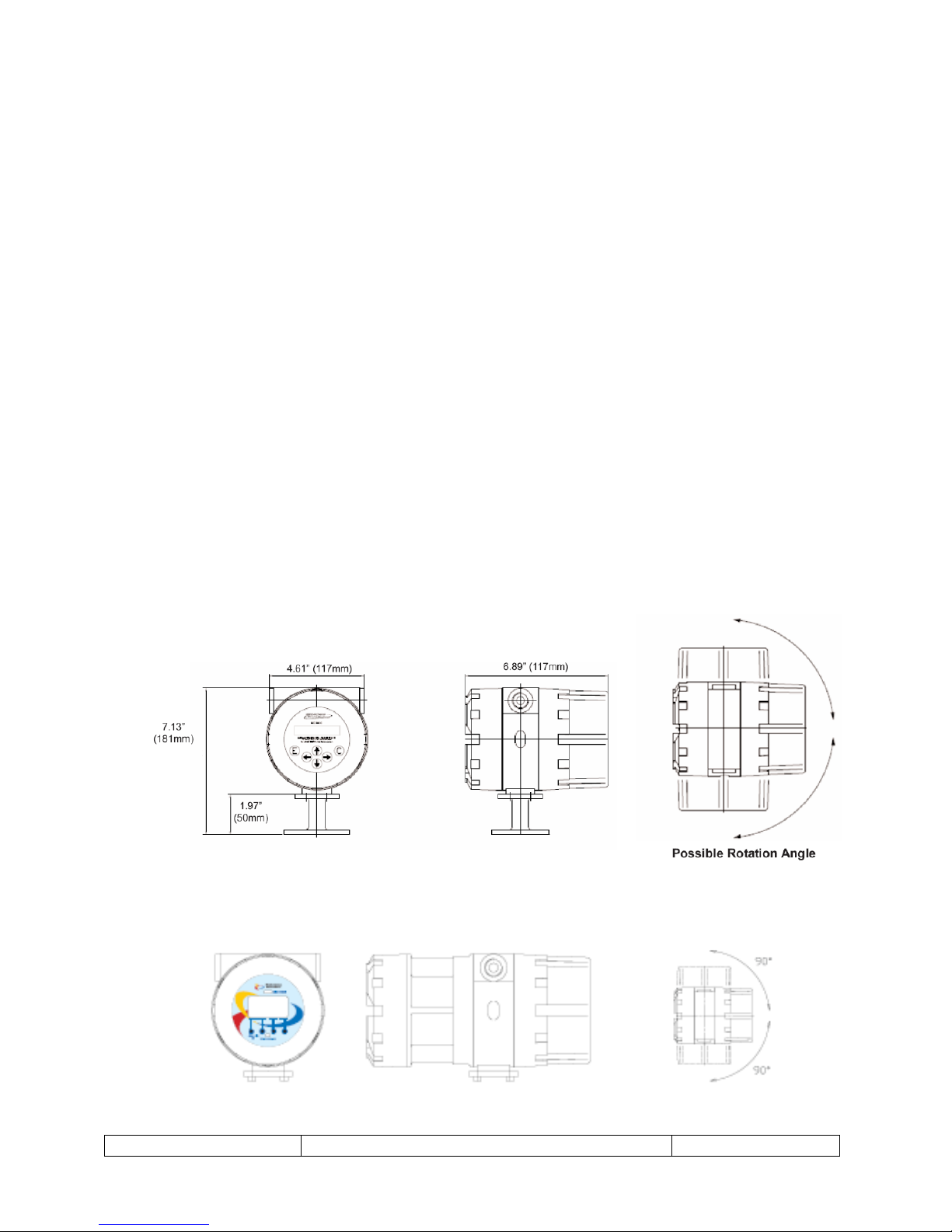
2.2.1 Compact (mounted on flow meter)
The MC 608A/B converter is supplied mounted directly to the flow meter junction box.
In this configuration all interconnection wiring between the flow meter sensor and the
converter have been completed at the factory. Upon flow meter installation, external
wiring for power input and signal outputs will need to be completed. For optimum
installation flexibility the converter display is capable of rotating up to 180˚.
Figure 1 – MC608A – Mains Powered Unit
Figure 2 – MC608B – Battery Powered Unit
SF-100834 Rev A
Page 10
TM-100467, Rev P
MC608A/B/P Transmitter Manual
Page 10
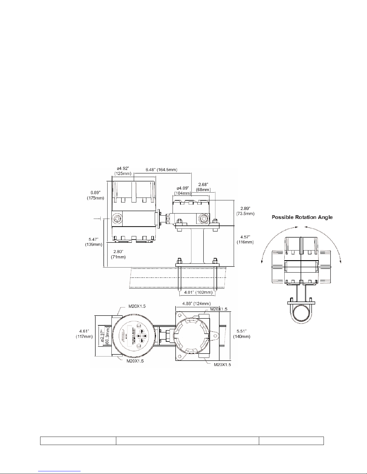
2.2.2 Separate (remote mounted from flow meter)
The MC 608A and MC 608B converters can be mounted up to a maximum of 328 feet
(100 meters) and 98 feet (30 meters) respectively from the flow meter, dependent on
fluid conductivity. When supplied for remote mounting, the flow meter can optionally
be purchased with various cable lengths for interconnection to the converter. This
interconnection cable can be supplied attached to and resin sealed in the flow meter
junction box or the cables can be supplied separately and attached and sealed in the
field. For optimum installation flexibility the converter display is capable of rotating up
to 180˚.
Figure 3 – Remote mounting
SF-100834 Rev A
Page 11
TM-100467, Rev P
MC608A/B/P Transmitter Manual
Page 11
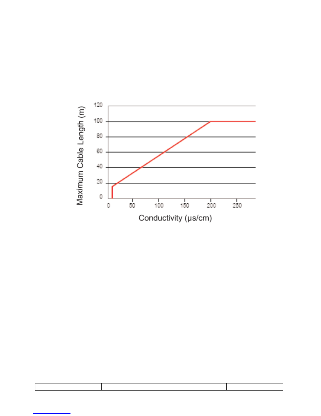
2.2.3 Maximum cable length
When the converter is to be mounted remote from the flow meter, the maximum cable
distance is limited by the conductivity of the fluid to be measured. The maximum
distance is 328 feet (100 meters). Below is a chart to determine maximum cable length
based on the installation operating conditions.
Figure 4 – Cable length vs. conductivity
2.2.4 Grounding
The sensor and converter must be properly grounded to earth potential for the system
to operate correctly. Earth potential is the reference parameter for the flow meter and
without proper grounding issues with zero offset, or flow indication at zero flow will
occur. The sensors and converters all have earth grounding points that can be used to
insure a direct contact with earth ground.
The Flow Technology electromagnetic flow meters are equipment with a third ground
electrode that eliminates the need for grounding rings when installing the flow meter in
insulating piping.
2.3 Electrical Installation
This section provides the professional installer with information for connecting the
MC608A/B to the user's system.
SF-100834 Rev A
Page 12
TM-100467, Rev P
MC608A/B/P Transmitter Manual
Page 12
Verify that the power is off before connecting or servicing!
Electrical connection of the device must be carried out by properly trained
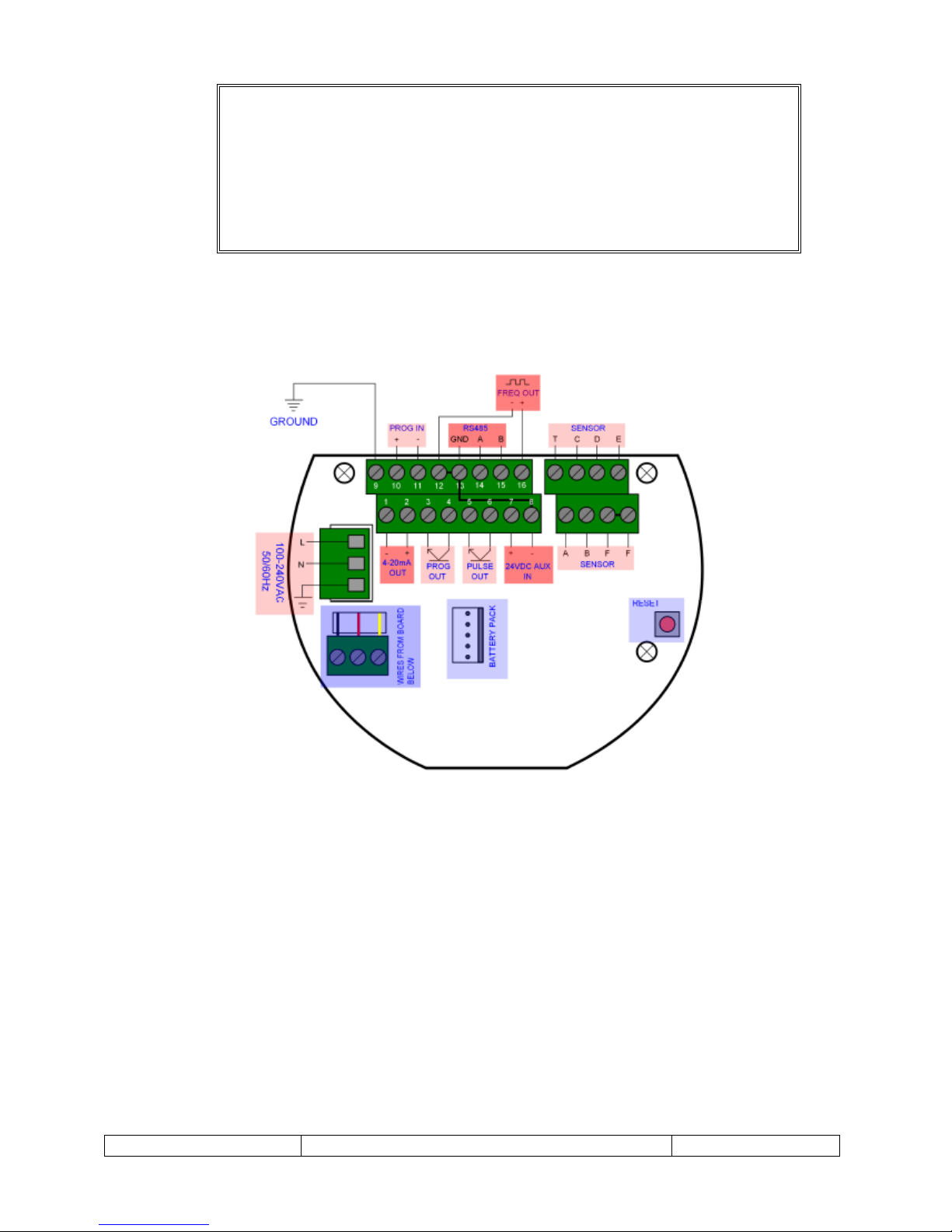
2.3.1 MC608A/B terminal locations
Figure 5- High voltage: 90 – 264 Vac (PCBA up to version 6-2)
WARNING:
personnel!
SF-100834 Rev A
Page 13
TM-100467, Rev P
MC608A/B/P Transmitter Manual
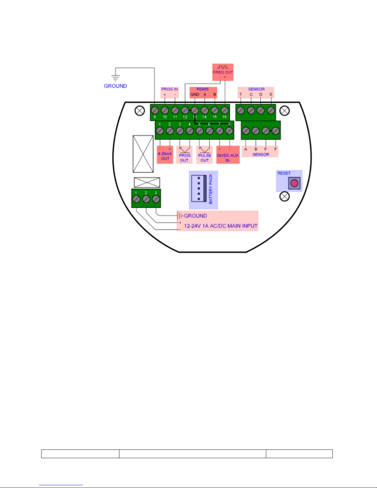
Page 13
Figure 6 – Low voltage: 12 – 24 VDC/Vac (PCBA up to version 6-2)
SF-100834 Rev A
Page 14
TM-100467, Rev P
MC608A/B/P Transmitter Manual
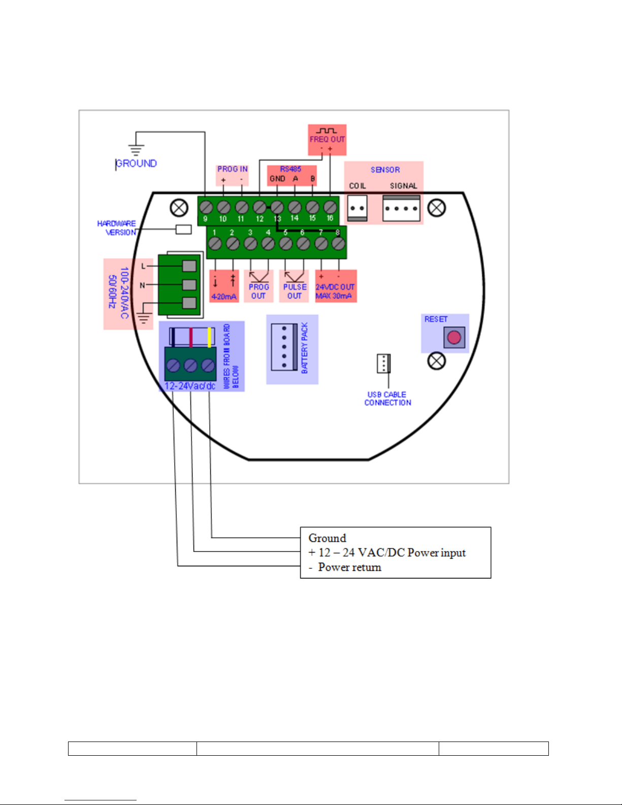
Page 14
Figure 7- Low and high voltage (PCBA version 6-3)
SF-100834 Rev A
Page 15
TM-100467, Rev P
MC608A/B/P Transmitter Manual
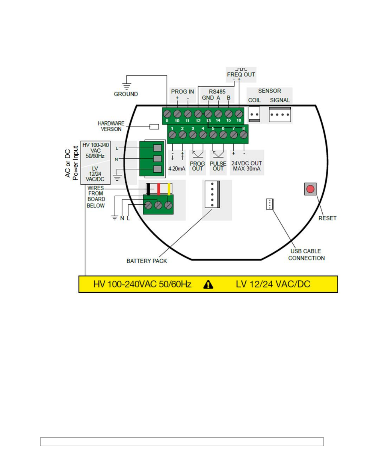
Page 15
Figure 8- Low and high voltage (PCBA from version 6-4)
Note: Line (L) and Neutral (N) terminals are not polarity sensitive when used with DC
power.
2.3.2 Remote mounted converter, without empty pipe detector
The remote mounted version of the MC 608A/B converter is supplied with an auxiliary
junction box where cables, C012 and C013 from the flow meter junction box will need to
be connected. The converter is normally supplied scaled for a specific flow meter. Please
check the program sheet supplied with the equipment to ensure the converter is
connected to the proper flow meter. Cables C012 and C013 are supplied with metal
ends and identifying letters. Refer to the diagram below for correct terminal location.
SF-100834 Rev A
Page 16

TM-100467, Rev P
MC608A/B/P Transmitter Manual
Page 16
Figure 9 – Remote mounted wiring
SF-100834 Rev A
Page 17

TM-100467, Rev P
MC608A/B/P Transmitter Manual
Page 17
2.3.3 Powering the unit
MC608A: 90 to 264 Vac, or 12 to 24 VAC/Vac
MC608B: Battery powered by lithium battery pack, or 12 to 24 VDC
2.3.4 Wiring of Pulse Output
Clean contact (MC608A/B)
The device connected (PLC/external pulse meter) supplies its digital input with the
required voltage to detect the pluses. The MC608 acts as a digital switch. (Maximum
voltage: 30VDC, 50mA maximum current)
Figure 10 – Clean contact pulse output
Active 5-20 VDC (MC608A/B)
The device connected (PLC/external pulse meter) is a passive digital input that accepts
the voltage supplied to it by the external supply system used. (Maximum voltage 5 – 30
VDC, maximum current 50mA)
SF-100834 Rev A
Page 18

TM-100467, Rev P
MC608A/B/P Transmitter Manual
Page 18
Figure 11 – Active 5 – 20 VDC pulse output
Active 24V self-powered (MC608A/B from version 6-3)
The device connected ((PLC/external pulse meter) is a passive digital input that accepts
a 24V voltage level. It must not provide any additional voltage. The internal power
supply 24 VDC is used to provide the necessary voltage. (Maximum voltage 24VDC,
maximum current 30mA).
Figure 12 – Active self-powered from version 6-3
SF-100834 Rev A
Page 19

TM-100467, Rev P
MC608A/B/P Transmitter Manual
Page 19
2.3.5 Wiring of Frequency Output (only available on MC608A version)
Figure 13 – Frequency output
2.3.6 Wiring of 4 – 20mA Analog Output
Loop powered (MC608 version 6-3 and later)
The connected 4-20mA receiver is a loop powered model, powering the current loop
itself.
Figure 14 – Loop 4 – 20 mA output
SF-100834 Rev A
Page 20

TM-100467, Rev P
MC608A/B/P Transmitter Manual
Page 20
Active (MC608 version 6-3 and later)
The connected 4-20mA receiver is a passive milliamp-meter; the internal MC608 24 VDC
power supply must be connected as shown. (24VDC loop voltage of 24 VDC, maximum
impedance of 800 ohm)
Figure 15 – Active 4 – 20 mA output
Active (MC608 version 6-1 and 6-2)
The connected 4-20mA receiver is a passive milliamp meter; the internal MC608 24 VDC
power supply is internally connected. (24VDC loop voltage of 24 VDC, maximum
impedance of 800 ohm.)
Figure 16 – Active 4 – 20 mA output
SF-100834 Rev A
Page 21

TM-100467, Rev P
MC608A/B/P Transmitter Manual
Page 21
2.3.7 Wiring of RS485 Output (only available on MC608A version)
Figure 17 – RS485 communication
Note: The MC608 transmitter is not supplied with a PC to RS485 converter. If
communication with the transmitter is require an aftermarket USB or RS232 to RS485
converter will be required.
2.3.8 Wiring of Programmable Output
Clean contact (MC608A/B)
The device connected provides its digital input with the required voltage to detect the
logic level. The MC608 acts as a digital switch. (Maximum voltage: 30 VDC, 50mA
maximum current)
Figure 18 – Clean contact programmable output
SF-100834 Rev A
Page 22

TM-100467, Rev P
MC608A/B/P Transmitter Manual
Page 22
Active 24V self-powered (MC608 version 6-3 and later)
The device is connected to a passive input that accepts a digital voltage equal to 24 V. It
must not provide any additional voltage.
The internal power supply 24 VDC is used to provide the necessary voltage. (Voltage
24V, maximum current 30mA)
Figure 19 – Active 24 V self-powered programmable output
Active 5-30V (MC608A/B)
The connected device is a passive digital input that accepts the voltage level provided by
the external power supply. (Voltage 5-30V, maximum current 50mA)
Figure 20 – Active 1-30V programmable output
SF-100834 Rev A
Page 23

TM-100467, Rev P
MC608A/B/P Transmitter Manual
Page 23
2.3.9 Wiring of Programmable Input
Figure 21 – Programmable input
2.3.10 Output Notes
1) Connect only one output at a time with internal power supply. The maximum current
on terminals 7 and 8 is 30 mA.
2) The battery powered MC608B is only equipped with a pulse output and the 4-20mA
output in loop power mode.
3 PROGRAMMING THE MC608 CONVERTER
3.1 Programming Overview
SF-100834 Rev A
Page 24

TM-100467, Rev P
MC608A/B/P Transmitter Manual
Page 24
The configuration of the MC608 can be performed in three different ways:
1. Through the 4 push buttons located on the front mask of the converter, accessed by
unscrewing the front panel glass
2. Via PC through the RS485 MODBUS output and the configuration software program
supplied by FTI. A USB or RS232 to RS485 converter is not supplied with the MC608
converter.
3. Via PC through the IrDA port located on the front of the converter on top of the display
and the configuration software program.
3.2 Converter Passwords
The converter is built with three different levels of protection. Passwords can be
modified.
Level I: 608111
Level II: 709222
Level III: 231042
3.3 Activating MC608B
Under normal operation the MC608B is operating in “sleep mode”. Sleep mode conserves
battery life while continuing to functionally operate the unit.
To wake the unit for programming or reading the values on the display, swipe the
supplied magnet (black plastic housing in conduit opening) vertically on the front mask
near the word “activate”.
3.4 MC608 Configuration via PC Using MC608 Programming Software
3.4.1 Initial Connection
Use a USB adapter for direct communication to a PC or an IrDA interface unit.
Install the MC608 software and connect the unit to the PC and turn it on with the
magnet (for MC608B), select RS485 or IrDA communication and press on the CONNECT
button (see below screen shot of the MC608 program).
SF-100834 Rev A
Page 25

TM-100467, Rev P
MC608A/B/P Transmitter Manual
Page 25
Figure 22 – Main Screen
With the MC608 correctly connected the configuration parameters can now be read and
modified. There are 5 menu screens:
1. PARAMETERS
2. READ
3. FILTERS
4. DATALog
5. CHART
SF-100834 Rev A
Page 26

TM-100467, Rev P
MC608A/B/P Transmitter Manual
Page 26
3.4.2 Parameter Configuration
Figure 23 – Parameters Screen
Technical units define:
The time base of measurement (seconds, minutes, hours, days)
Flow Rate Volume defines the volumetric rate units of measure (Gals, Liters, Cubic
meters, barrels etc.)
Counters Volume defines the volumetric unit of measure for the counters/totalizers.
The I/O section defines:
Pulses volume TU – unit of measure for the pulse & frequency outputs.
Pulse volume – defines the volume per unit pulse.
Pulse width
FS Frequency defined the output frequency corresponding to full scale flow rate.
The maximum frequency 10,000Hz.
Mode AUX3 – programmable output used for high/low alarm or reverse flow.
Ing. Prog. – programmable input used for reset of partial totals.
SF-100834 Rev A
Page 27

TM-100467, Rev P
MC608A/B/P Transmitter Manual
Page 27
The Alarm section defines:
Min Flow Rate Alarm. Defines the % of full scale flow such that if the flow rate falls
below this set point an alarm will be activated.
Max Flow Rate Alarm. Defines the % of full scale flow such that if the flow rate
exceeds this set point an alarm will be activated.
The LCD section defines:
Display contrast
Backlight intensity
How long the display will remain active.
The DataLogger section defines:
The logging interval. This can be set from 4 seconds to 16 minutes.
3.4.3 Read Configuration
On the “READ” configuration Tab the user can view the instantaneous flow rate and
view the counters/totalizers. Only the “PARTIAL” totals can be reset to zero by pressing
the respective zero button.
Figure 24 – Read Screen
SF-100834 Rev A
Page 28

TM-100467, Rev P
MC608A/B/P Transmitter Manual
Page 28
3.4.4 Filter Configuration
Figure 25 – Filter Screen
The following filters can be configured:
Damping. Increasing damping increases the stability of the displayed value through
Peak Cut: A peak cut off value can be set as a percentage of the full scale flow rate.
Low Flow Cut Off. A low flow cut off value can be set as a percentage of the full
Filter Bypass. Enter a value as percentage of full scale so that any instantaneous
For example, in the case that this parameter has a value of 50%
SF-100834 Rev A
increased averaging; the larger the number the higher the damping.
If there are peaks in the flow rate measurement, their value will be limited to the
value expressed. For example, by setting the value at 10%, any instantaneous spikes
greater than 10% of the full scale value will be limited not to exceed the 10% value.
scale flow rate. If the actual flow rate of the liquid is less than the low flow cut off
value, then the instrument will display 0.
step changes greater than the set value will bypass the digital filter and display the
actual flow. The filter bypass can be useful to speed the response of the meter to
large changes in flow rate such as opening or closing valves and starting pumps.
Page 29

TM-100467, Rev P
MC608A/B/P Transmitter Manual
Page 29
IF: The flow rate varies 50% more than the previous value.
THEN: The flow rate shown will reflect the actual step change
IF: The flow step change is less than 50% of the full scale value
THEN: The digital filter will be applied and the flow rate shown will slowly reach the
actual value.
Measurement Average. This option increases the stability of the reading by
enlarging the actual measurement filter.
3.4.5 Data Logger
The data logger that was configured on the PARAMETERS tab displays: Date, time,
counter, instantaneous flow rate, temperature and battery condition.
Figure 26 – Data Logger Screen
To read and download the data from the memory of the flow meter select the START
and END row to read the data. The “Get Last Log” will load the last available log.
Press the READ Log button to download the data,
SF-100834 Rev A
Page 30

TM-100467, Rev P
MC608A/B/P Transmitter Manual
Page 30
Press SAVE CSV to save the data to your PC in CSV format.
Press “Reset Data Log” button to erase the memory of the converter.
After reading the data, the data is displayed graphically by going to the CHART tab, see
picture below:
Figure 27 – Chart Display Screen
3.5 MC608 Configuration via the Local Display
3.5.1 Overview
The MC608 can be configured using the 4 push buttons located on the front mask of the
converter: To access unscrew the front cover.
The programming menu is simply accessed by pressing the Menu button. The menu has
been divided into the following groups:
Options
SF-100834 Rev A
Page 31

TM-100467, Rev P
MC608A/B/P Transmitter Manual
Page 31
Counters
Parameters
I/O
Others
Memory
Follow the chart below for an overview of the available functions.
SF-100834 Rev A
Page 32

TM-100467, Rev P
MC608A/B/P Transmitter Manual
Page 32
3.5.2 Data to be Displayed
The display is divided into 3 mil areas.
The top area shows the symbols for status information, together with the indication on
the duration of the battery (MC608B), or power indication (MC608A), as well as the
alarm symbols and instantaneous reading of the flow rate.
The central area shows a linear graph of the flow rate shown in percentage on the full
scale flow rate.
The area at the bottom can be selected by the customer and the possible options are:
o T+ total positive counter
o P+ partial positive counter
o T- total negative counter
o P- partial negative counter
o Date and time
To select the required value simply click on the button corresponding to the arrow and
make your selection, or select Menu ˃ Options ˃ View ˃ Options ˃ Last row.
Figure 28 – Display Overview
SF-100834 Rev A
Page 33

TM-100467, Rev P
MC608A/B/P Transmitter Manual
Page 33
3.5.3 Options
3.5.3.1 Technical Units
Flow rate volume: Select the volume technical unit for the instantaneous flow rate
Flow time base: Select the time base for the instantaneous flow rate.
Counter volume: Select the volume technical unit for the counters
Pulse volume: Select the volume unit for the pulses.
3.5.3.2 Measurement Frequency
Measuring time. If operating in battery powered mode, select the measuring time
of the system between 16 and 120 seconds.
Note: The factory setting is 32 seconds. Any reduction of the factor will affect
battery life when using MC608B in battery mode.
3.5.3.3 Display
LCD Backlight Level. Increase or decrease the level of the backlight.
Backlight off. Increase or decrease shut off time of the backlight of the display.
LCD contrast. Modify the contrast of the display.
Note: Any modification of the display can affect battery life when using the MC608B
in battery mode.
3.5.3.4 View Options
Defines the default display information with selection between:
o T+ total positive counter
o P+ partial positive counter
o T- total negative counter
o P- Partial negative counter
o Date & time
3.5.3.5 Language
The following languages may be selected:
o English
o Spanish
o Portuguese
o Italian
3.5.4 Counters
Four different counters are available in the MC608 converter. Two positive counters,
and two negative counters. Only partial counters can be set to zero.
SF-100834 Rev A
Page 34

TM-100467, Rev P
MC608A/B/P Transmitter Manual
Page 34
3.5.5 Parameters
3.5.5.1 Ka Setup
KA is the main calibration factor of the flow meter – this location allows the user to
modify the calibration factor if required.
Note: Only authorized personnel should change the Ka factor. The Ka factor must be
the same as the flow meter sensor. Check the Ka factor on the flow meter name
plate.
3.5.5.2 Diameter Setup
This location allows the user to set the diameter of the flow meter.
3.5.5.3 Filter Setup
Flow cutoff. A low flow cut off value can be set as a percentage of the full scale flow
rate. If the actual flow rate of the liquid is less than the low flow cut off value, then
the instrument will display 0.
Damping. Increasing damping increases the stability of the displayed value through
increased averaging; the larger the number the higher the damping.
Peak Cut: A peak cut off value can be set as a percentage of the full scale flow rate.
If there are peaks in the flow rate measurement, their value will be limited to the
value expressed. For example, by setting the value at 10%, any instantaneous spikes
greater than 10% of the full scale value will be limited not to exceed the 10% value.
Filter Bypass. Enter a value as percentage of full scale so that any instantaneous
step changes greater than the set value will bypass the digital filter and display the
actual flow. The filter bypass can be useful to speed the response of the meter to
large changes in flow rate such as opening or closing valves and starting pumps.
For example, in the case that this parameter has a value of 50%
IF: The flow rate varies 50% more than the previous value.
THEN: The flow rate shown will reflect the actual step change
IF: The flow step change is less than 50% of the full scale value
THEN: The digital filter will be applied and the flow rate shown will slowly reach
the actual value.
Measurement Average. This option increases the stability of the reading by
enlarging the actual measurement filter. To increase the stability, increase the value
in this sub-menu.
3.5.5.4 Sensor Offset
Displays the zero offset of the flow meter
SF-100834 Rev A
Page 35

TM-100467, Rev P
MC608A/B/P Transmitter Manual
Page 35
3.5.5.5 Zero Finder
This setting is used to perform the instrument zero calibration. Before performing
the zero calibration ensure that:
o The sensor is full of liquid
o The liquid is perfectly stationary
o The sensor has the correct electrical ground
3.5.5.6 Flow Rate Alarms
Max flow: Set the maximum value of the flow rate as a percentage of the full scale
value. The factor default setting is “disabled”. The max flow threshold by be set
from 5% to 200% of the full scale value. Setting this parameter to 200% disables this
function.
Min flow: Set the minimum value of the flow rate as a percentage of the full scale
value. The factor default setting is “disabled”. The min flow threshold by be set
from 1% to 5% of the full scale value. Setting this parameter to 1% disables this
function
3.5.6 I/O
3.5.6.1 Pulse Out
Pulse Quantity
Define the pulse significance i.e. volume / unit pulse. Note: pulse volume and
duration settings differ between transmitter models MC608A and MC608B
- MC608A (powered version) Parameter calculation.
Vp = volume per pulse expressed in liters
Tp = Pulse width expressed in seconds
Q = flow rate in liters / second
For a given pulse width (Tp): Vp > Qmax*2Tp
For a given volume per pulse (Vp): Tp < Vp/2Qmax
- MC608B (battery version) Parameter calculation.
For a given pulse width (Tp): Vp > Qmax*20Tp
For a given volume per pulse (Vp): Tp < Vp/20Qmax
Pulse time on
o Select the “on” time duration of the pulse on a range between 1 and 1999 ms.
Reverse flow (off/on)
SF-100834 Rev A
Page 36

TM-100467, Rev P
MC608A/B/P Transmitter Manual
Page 36
o Acting on this function, in the case of negative flow, the pulses will be
enabled/disabled.
Note: High pulse output frequencies and “on” times longer than 100 ms will
adversely affect battery life.
3.5.6.2 Frequency Output
Full scale frequency: Set the maximum frequency corresponding to the full scale
flow rate value. The selectable range is 100Hz to 10KHz.
3.5.6.3 Program Output
The programmable status output can be set to:
o Enable/disable
o Reverse flow
o Max flow alarm
o Min flow alarm
o Batching
o Excitation failure
o Empty Pipe
3.5.6.4 Program Input
The programmable input can be set to:
o External partial positive total zeroing
o External partial negative total zeroing
o External partial positive and negative total
3.5.7 Other
3.5.7.1 System Info
Displays the system information. These values cannot be modified by the end user
3.5.7.2 Time/Date
Shows the date, time, motherboard temperature, battery condition for the MC608B
battery powered unit.
3.5.7.3 Graph
Displays the graph of measured flow rate.
3.5.7.4 Simulation
The MC608 has a built in flow simulator to verify and adjust the pulse output to any
connected device.
Note: When using the flow simulation, the counters will not increase in value.
SF-100834 Rev A
Page 37

TM-100467, Rev P
MC608A/B/P Transmitter Manual
Page 37
3.5.7.5 Communication
Baud rate. Allows the adjustment of the RS485 baud-rate between the range 2400
and 115,700 bps.
MODBUS address. Allows the adjustment of the MODBUS communication address
between 1 and 255.
3.5.8 Memory
3.5.8.1 Load User Copy
Allows to load customized settings
3.5.8.2 Save User Copy
Allows to save customized settings
3.5.8.3 Load Factory Settings
Allows to load factory settings
3.5.8.4 Data Logger
Show last row: Displays last information logged. Date, time, counter, instantaneous
flow rate, temperature, battery condition.
3.5.8.5 Full Erase
Erases the memory of the converter
3.5.8.6 Log Interval
Defines logging interval. 1 minute minimum / maximum 120 minutes
SF-100834 Rev A
Page 38

TM-100467, Rev P
MC608A/B/P Transmitter Manual
Page 38
4 SPECIFICATIONS
Parameter
Specification
Converter Installation
Compact or remote versions
MC608A up to 100 meters from sensor
MC608B up to 30 meters from sensor
Converter Case
Aluminum epoxy painted IP68 rated to 1.5 meters, with front
window in toughened glass. Note: Coolant version (MC608P) is
IP66 rated.
Electrical Connections
Cable glands, plastic, M20x1.5
Connection Cables
Supplied by FTI
Power Supply
MC608A
90…264Vac
12/24 Vac/dc
MC608B
Battery powered supply or 12/24Vac/dc
Expected life T=0/50°C – Internal battery pack 3-6 years;
internal and external battery pack 6-10 years
Inputs / Outputs
Active analog 4-20mA
Digital pulse output maximum 1000Hz duty cycle max 50%
Programmable digital output
Digital pulse output active frequency 0…10kHz (requires
external 24VDC)
All outputs are optically isolated
Pulse output maximum capacity +/- 30VDC 50mA
Serial Communication
MODBUS RTU interface on RS485
IrDA interface for communicating with laptop or hand held
device.
Temperature Range
Ambient: -20°C to 80°C (-4°F to 176°F)
Storage: -30°C to 80°C (-22°F to 176°F)
Accuracy
0.20% of reading value (over calibrated range)
Repeatability
0.10% of reading value
Sampling Frequency
Programmable 5, 3, 1, 1/15, 1/30, 1/60, 1/120, 1/240, 1/480 Hz
Measuring Stability Time
3 seconds
Display
Graphic LCD – 128x64 pixels, 50x25mm visual area
Programmable backlighting
Simultaneous display of rate, totals, status flags
Programmable display content
SF-100834 Rev A
Page 39

TM-100467, Rev P
MC608A/B/P Transmitter Manual
Page 39
Parameter
Specification
Programming
With push buttons on display PCB
By PC with dedicated software via RS485 MODBUS RTU
communication protocol.
By Irda interface with laptop or hand held device
Units of Measure
Settable for individual counters, flow indication and pulse o/p
USgal, bbl, oz, gal, ft3, in3, m3,hl, dal, l, dl, cl, ml
Reference Time
Selectable time units: s, m, h, days
Process Data Logger
4MB flash memory, 200,000 lines of data (one line includes:
instant flow, 2 counters, date, time, PCB temperature).
Diagnostic Data Logger
64Kb EEPROM, 2000 lines of data (one line includes: date, time,
PCB temperature, error codes, user actions with changes made).
Not programmable and tamper/reset proof.
Electrical Conductivity
5uS/cm, 20uS/cm minimum for DI water
Recommended Velocity
-10 to 10 m/s
Approvals
MC 608 A/B meets all the requirements established by the
EC directives.
Electromagnetic compatibility: Directive 2004/108/EC,
Harmonized standards EN 61326-1:2006; EN 55011:2009;
EN61000-3 (2/3); EN 61000-4 (2/3/4/5/6/8/11)
Low voltage directive: Directive 2006/95/EC
SF-100834 Rev A
Page 40

TM-100467, Rev P
MC608A/B/P Transmitter Manual
Page 40
5 TROUBLESHOOTING
Symptom
Possible Remedies
Converter is showing a flow rate with no flow.
1) Check if the sensor and liquid are
correctly grounded.
2) Check that the sensor is full of fluid.
3) Electrical conductivity of the fluid is too
low or is not compatible with the material
used for the sensor electrodes.
4) Perform manual zero finder. (Menu –
Parameters, sub menu – zero finder)
5) Check value of low flow cut off.
Flow Reading is highly unstable.
1) Check if the sensor and liquid are
correctly grounded.
2) There is air in the pipe. Avoid bubbles by
selecting a more suitable position for the
sensor.
3) Set filters as follows:
Set Damping to 150
Reduce Peak Cut filter
Increase Bypass filter
External pulse totalizer shows results different
from what is expected.
1) Test the output with the internal flow
simulator and the converter pulse counter
system simulating a flow rate with System
– Simulator.
The display is off and does not turn on.
1) Check to insure supply voltage is
available.
2) Check that supply voltage matches the
name plate on the converter.
3) If the unit is a MC608B battery powered
unit, check the battery life and replace as
needed.
Liquid is flowing in pipe, but there is no
display,
1) Reduce the low flow cut off filter (factory
setting is 2% of the full scale)
SF-100834 Rev A
Page 41

TM-100467, Rev P
MC608A/B/P Transmitter Manual
Page 41
6 ALARM MESSAGES
Alarm Message
Possible Cause and Solutions
Excitation failure
1) Incorrect cable connections.
2) Sensor damaged. Damaged lining or
electrodes. Possible infiltration of liquid
inside the sensor.
3) Converter damaged.
Recommend performing a test on the
sensor circuit between coils A – B: 50 – 250
Ohm.
Measurement error
Check for correct installation of sensor.
With pipe full between a or B and ground ˃
100MOhm.
Empty Pipe
This message is displayed with sensors that
have 4 electrodes. Indicates the alarm of
empty pipe, or partially empty.
If the alarm is indicating the pipe is
partially full when you are sure it is full, go
to:
Main Menu, Parameters, Empty Pipe Th.
Move the slide bar toward the “F” and
press “test”. The alarm should be
removed.
Pulse accumulation
1) Pulse frequency incorrect
Change the volume and/or pulse duration
settings.
Supply voltage
1) Supply voltage out of operating range
2) Converter damaged
Check the power supply network.
Data logger full
Download the data to a PC and erase the
memory of the converter.
SF-100834 Rev A
Page 42

TM-100467, Rev P
MC608A/B/P Transmitter Manual
Page 42
Appendix A Coolant Flow Meter Transmitter (MC608P)
The EL4000 series coolant meters have a unique transmitter configuration and enclosure. The
flow meter and transmitter come prewired with six meters of cable and a cable interconnection
a short distance from the flow meter. The transmitter enclosure is light weight plastic which can
be panel or wall mounted. The wiring and programming of the coolant transmitter (MC608P) is
the same as the MC608A version defined in this manual. Dimensional information for the
transmitter housing is provided below.
SF-100834 Rev A
Page 43

TM-100467, Rev P
MC608A/B/P Transmitter Manual
Page 43
Appendix B Modbus Input Registers - Function Code 04
MODBUS
REGISTER
MODBUS
ADDRESS
Num.
Bytes
Data
Type
Description
DATA TYPE
Access
(Read/Write)
3:0001
0000
4
FLOAT
Instantaneous measurement fluid velocity in m/s
m/s
R
3:0003
0002
4
FLOAT
Instantaneous measurement flow rate in m3/s
m3/s
R
3:0005
0004
4
FLOAT
Instantaneous measurement flow rate in kg/s
kg/s
R
3:0007
0006
4
FLOAT
Counter total positive in m3
m3
R
3:0009
0008
4
FLOAT
Counter total negative in m3
m3
R
3:0011
0010
4
FLOAT
Counter partial positive in m3
m3
R
3:0013
0012
4
FLOAT
Counter partial negative in m3
m3
R
3:0015
0014
4
FLOAT
Specific weight set for mass counters in kg/m3
kg/m3
R
3:0017
0016
4
FLOAT
Counter total positive in kg
kg
R
3:0019
0018
4
FLOAT
Counter total negative in kg
kg
R
3:0021
0020
4
FLOAT
Counter partial positive in kg
kg
R
3:0023
0022
4
FLOAT
Counter partial negative in kg
kg
R
3:0025
0024
2
INT16
Index volume unit current flow rate
See volume units table
R
3:0026
0025
2
INT16
Index volume unit current time flow rate
See time units table
R
3:0027
0026
4
FLOAT
Measure instantaneous fluid flow in the units set
Reg-0024 / reg-0025
R
3:0029
0028
2
INT16
Index volume unit counter current set
See volume units table
R
3:0030
0029
4
FLOAT
Counter total positive in the current volume unit
reg-0028
R
3:0032
0031
4
FLOAT
Counter total negative in the current volume unit
reg-0028
R
3:0034
0033
4
FLOAT
Counter partial positive in the current volume unit
reg-0028
R
3:0036
0035
4
FLOAT
Counter partial negative in the current volume
unit
reg-0028
R
3:0038
0037
4
FLOAT
Pulse volume in m3
m3
R
3:0040
0039
2
INT16
Pulse volume in the current volume unit
See volume units table
R
3:0041
0040
4
FLOAT
Pulse volume in the set volume unit
reg-0039
R
3:0043
0042
4
FLOAT
PCB temperature
°C/°F
R
3:0047
0046
2
INT16
Sampling Frequency
0: Continuous *
1: Battery *
2: Any
3: Continuous
4: Seconds
R
3:0048
0047
2
INT16
Current year
YY
R
3:0049
0048
2
INT16
Current month
MM
R
3:0050
0049
2
INT16
Current day
DD
R
3:0051
0050
2
INT16
Hours
hh
R
3:0052
0051
2
INT16
Minutes
mm
R
3:0054
0053
4
FLOAT
Full scale (FS) in the current volume unit *
reg-0024/reg-0025
R
3:0056
0055
4
FLOAT
Actual flow rate % on the FS *
%
R
FC04 Read Input Registers (read-only variables)
(*)FW version 3.00 and later
SF-100834 Rev A
Page 44

TM-100467, Rev P
MC608A/B/P Transmitter Manual
Page 44
Appendix C Modbus Holding Register Function Codes 03 & 16
MODBUS
REGISTER
MODBUS
ADDRESS
Num.
Bytes
Data
Type
Description
DATA TYPE
Access
(Read/Write)
CMD16 (*)
4:1002
1001
2
UINT
Firmware version FW
0207hex=2.07
R
4:1003
1002
2
UINT
Hardware version HW
0501hex=5.01
R
4:1004
1003
2
UINT
Baudrate (TIA-485)
Default 9600
R
4:1005
1004
2
BYTE
Device Modbus 1-255
Default 1
R
4:1006
1005
2
BOOL
Format FLOAT on Modbus
0=FLOAT (default)
1=Reverse FLOAT
R/W
4:1011
1010
2
BYTE
Reserved
Reserved
R/W
4:1012
1011
2
UINT
Reserved
Reserved
R/W
4:1020
1019
8
ASCII
Converter model
8 digits - ex.: “MC 608B”
R
4:1024
1023
10
ASCII
Converter’s part number
Factory value (9 digits)
R
4:1029
1028
4
ULONG
Converter’s serial number
Progressive production number
R
4:1031
1030
12
UINT
Coupled sensor model
12 digits - ex.: “MUT1100J”
R
4:1037
1036
10
ASCII
Sensor’s part number
Factory value (9 digits)
R
4:1042
1041
2
UINT
Coupled sensor’s diameter
Diameter (1 - 4000) mm
R
4:1043
1042
2
BYTE
Empty pipe
1=available; 0=not available
R
4:1045
1044
20
BYTE
Note
Internal references
R
4:1055
1054
4
FLOAT
Full scale m3/h
Referent value alarms/display
R/W
4:1061
1060
2
BYTE
Percentage back light level display
0 - 100 %
R/W
4:1062
1061
2
BYTE
Time-out back light display
0 - 30 second
>30 always on
R/W
4:1063
1062
2
BYTE
LCD contrast
24 - 50
R/W
4:1064
1063
2
BYTE
Language display
0=English
1=Italian
2=Spanish
3=Portuguese
4=French *
R/W
4:1065
1064
2
BYTE
Set last line of the display
0=Total positive counters;
1=Partial positive counters;
2= Total negative counters;
3=Partial negative counters;
4=Date; *
5 = Exp; *
R/W
4:1066
1065
2
BYTE
Flow rate volume
See volume units table
R/W
4:1067
1066
2
BYTE
Time base flow rate time
See time units table
R/W
4:1068
1067
2
BYTE
Totalizers volume
See volume units table
R/W
4:1069
1068
2
UINT
Liquid specific weight value *
kg/m3
R/W
4:1070
1069
2
BYTE
Temperature units *
0 = °C
1 = °F
R/W
4:1071
1070
2
BYTE
Visualized pulses on display
See volume units table
R/W
4:1072
1071
4
FLOAT
Pulse volume in ml
Value x 0.1
* Value
R/W
4:1074
1073
2
UINT
Pulses time ON
(value +1) x 0.5 mS
* 1 - 1999 mS (def 10)
R/W
FC03 – Read Holding Register
FC16 – Write Holding Register
SF-100834 Rev A
Page 45

TM-100467, Rev P
MC608A/B/P Transmitter Manual
Page 45
4:1077
1076
2
BYTE
Pulses/frequency output Mode *
0= Out pulses + Out Freq :
PWM
1 = Only frequency Out
R/W
4:1078
1077
2
BYTE
Enable pulses also with negative flow *
0 = Off
1= On
R/W
4:1081
1080
2
BYTE
Programmable input setup
0=Disabled
1=Set zero P2=Set zero P+
3=Set zero P+ e P-
R/W
4:1082
1081
2
BYTE
Programmable output setup
0=Disabled
1=Reverse flow
2= Max flow threshold
3= Min flow threshold
4= Max/min threshold
5= Dosage *
6 = Excitation failure *
7 = Empty pipe alarm *
R/W
4:1083
1082
2
UINT
Frequency out full scale
100 - 10000 Hz
R/W
4:1084
1083
2
BYTE
Programmable output logic *
0 = Norm. Open
1 = Norm. Closed
R/W
4:1085
1084
4
FLOAT
Dosage volume *
1 - 1000000 (TU Counters)
R/W
4:1101
1100
2
UINT
Damping Filter (average number of
samples visualized) **
5 - 500
1 – 500 *
R/W
4:1102
1101
2
BYTE
Percentage cut-off
0 - 50 % FS (def 2%)
R/W
4:1103
1102
2
BYTE
Percentage by-pass filter
2 - 95 % FS ( def 10%)
R/W
4:1104
1103
2
BYTE
Percentage peak-cut
1 - 25 % FS ( def 5%)
R/W
4:1105
1104
2
BYTE
Line frequency 50hz/60Hz
50Hz , 60Hz
R/W
4:1106
1105
2
UINT
Average filter
1 - **Damping
R/W
4:1111
1110
2
BYTE
Flow rate alarm (MAX) on the FS
5% - 100%
*(MIN + 5%) - 100%
255 = OFF
R/W
4:1112
1111
2
BYTE
Flow rate alarm (MIN) on the FS
1% - (MAX – 5%)
*0% - (MAX – 5%)
255 = OFF
R/W
4:1132
1131
2
BYTE
Datalogger sampling frequency
Value (1 - 240) x 4 sec
* 1 - 120 minutes
R/W
(*) FW version 3.00 and later
FS = Full scale
SF-100834 Rev A
Page 46

TM-100467, Rev P
MC608A/B/P Transmitter Manual
Page 46
Appendix D Volume and Time Base Units Charts
Volume Units
1 2 3 4 5 6 7 8 9
10
11
12
13
ml
cl
dl l dal
hl
m3
Ml
in3
ft3
gal
bbl
oz
Time Units
1 2 3
4
/s
/min
/h
/GG
SF-100834 Rev A
Page 47

TM-100467, Rev P
MC608A/B/P Transmitter Manual
Page 47
Appendix E Examples
address
function
register word 03EDhex
data count word 0001hex
CRC 16 word
data start
address HI
data start
address LOW
data BYTE
count HI
data BYTE count
LOW
CRC LOW
CRC HI
Device ID (1-255)
03
03h
EDh
00 1 CRC16
address
function
data BYTE
count
register 00AFhex word value
CRC 16 word
data BYTE
HI
data BYTE LOW
CRC LOW
CRC HI
Device ID
03 2 00
0=FLOAT
1=FLOAT reverse
CRC16
address
function
register word
03EDhex
data count word
0001hex
data BYTE
count
register 00AFhex word
value
CRC 16 word
data
start
address
HI
data
start
address
LOW
data
BYTE
count
HI
data
BYTE
count
LOW
data
BYTE HI
data BYTE LOW
CRC
LOW
CRC HI
Device ID
(1-255)
16
03h
EDh
00
01h
2h
00
0=FLOAT
1=FLOAT
reverse
CRC16
address
function
register word 03EDhex
data count word 0001hex
CRC 16 word
data start
address HI
data start
address
LOW
data BYTE
count HI
data BYTE
count LOW
CRC
LOW
CRC HI
Device ID
16
03h
EDh
00
01h
CRC16
Address 1005 - FLOAT ON MODBUS FORMAT
This setting inverts the order of the two words making up the 32-bit FLOAT and allows you to read and write data
as FLOAT or FLOAT reverse
Address 1005=03EDh Reading required description
Query chart
Read response explanation
Response example chart
Write request description
Query chart
Write response explanation
Response example chart
SF-100834 Rev A
Page 48

TM-100467, Rev P
MC608A/B/P Transmitter Manual
Page 48
Example R/W BYTE Register
address
function
register word 03F2hex
data count word 0001hex
CRC 16 word
data start
address HI
data start
address LOW
data BYTE
count HI
data BYTE count
LOW
CRC LOW
CRC HI
Device ID (1-255)
03
03h
F2h
00 1 CRC16
address
function
data BYTE
count
register 03F2hex word value
CRC 16 word
data BYTE HI
data BYTE LOW
CRC LOW
CRC HI
Device ID
03 2 00
20 - 240 s
CRC16
address
function
register word
03F2hex
data count word
0001hex
data BYTE
count
register 03F2hex word
value
CRC 16 word
data
start
address
HI
data
start
address
LOW
data
BYTE
count
HI
data
BYTE
count
LOW
data
BYTE HI
data BYTE
LOW
CRC
LOW
CRC HI
Device ID
(1-255)
16
03h
F2h
00
01h
2h
00
20 - 240 s
CRC16
address
function
register word 03F2hex
data count word 0001hex
CRC 16 word
data start
address HI
data start
address
LOW
data BYTE
count HI
data BYTE
count LOW
CRC
LOW
CRC HI
Device ID
16
03h
F2h
00
01h
CRC16
Address 1010 – AUTOMATIC POWER OFF TIME (batteries)
This value represents the time (in seconds) of the automatic power-off, exclusively for the version with battery
power supply
Address 1010=03F2h Read request description
Query chart
Write request description
Response example chart
Write request description
Query chart
Write request description
Response example chart
SF-100834 Rev A
Page 49

TM-100467, Rev P
MC608A/B/P Transmitter Manual
Page 49
Example R/W Unit Register
address
function
register word 0411hex
data count word 0001hex
CRC 16 word
data start
address HI
data start
address LOW
data BYTE
count HI
data BYTE count
LOW
CRC
LOW
CRC HI
Device ID (1-255)
03
04h
11h
00 1 CRC16
address
function
data BYTE
count
register 0411hex word value
CRC 16 word
data BYTE HI
data BYTE LOW
CRC LOW
CRC HI
Device ID
03 2 1 - 4000 mm
CRC16
address
function
register word
0411hex
data count word
0001hex
data BYTE
count
register 0411hex word
value
CRC 16 word
data
start
address
HI
data
start
address
LOW
data
BYTE
count
HI
data
BYTE
count
LOW
data
BYTE HI
data BYTE
LOW
CRC LOW
CRC HI
Device ID
(1-255)
16
04h
11h
00
01h
2h
1 - 4000 mm
CRC16
address
function
register word 0411hex
data count word 0001hex
CRC 16 word
data start
address HI
data start
address
LOW
data BYTE
count HI
data BYTE
count LOW
CRC
LOW
CRC HI
Device ID
16
04h
11h
00
01h
CRC16
Address 1041 – SETTING THE COUPLED SENSOR DIAMETER
This value indicates the diameter of the coupled sensor in mm
Address 1041=0411hRead request description
Query chart
Read request description
Response example chart
Write request description
Query chart
Write request description
Response example chart
SF-100834 Rev A
Page 50

TM-100467, Rev P
MC608A/B/P Transmitter Manual
Page 50
Example R/W FLOAT Register
address
function
register word 041Ehex
data count word 0001hex
CRC 16 word
data start
address HI
data start
address LOW
data BYTE
count HI
data BYTE count
LOW
CRC
LOW
CRC HI
Device ID (1-255)
03
04h
1Eh
00 2 CRC16
address
function
data BYTE
count
register 041Ehex word
value
register 041Fhex word
value
CRC 16 word
data BYTE HI
data BYTE
LOW
data BYTE HI
data BYTE
LOW
CRC LOW
CRC HI
Device ID
03
4
word LOW
word HI (FLOAT reverse)
word HI
word LOW (FLOAT reverse)
CRC16
address
function
register word
041Ehex
data count
word 0002hex
data
BYTE
coun
t
register 041Ehex
word value
register 041Fhex
word value
CRC 16
word
data
start
address
HI
data start
address
LOW
data
BYTE
count
HI
data
BYTE
count
LOW
data
BYTE
HI
data
BYTE
LOW
data
BYTE
HI
data
BYTE
LOW
CRC
LO
W
CRC
HI
Device ID
(1-255)
16
04h
1Eh
00
02h
4h
word LOW
word HI (FLOAT
reverse)
word HI
word LOW (FLOAT
reverse)
CRC16
address
function
register word 041Ehex
data count word 0002hex
CRC 16 word
data start
address HI
data start
address
LOW
data BYTE
count HI
data BYTE
count LOW
CRC LOW
CRC HI
Device ID
16
04h
1Eh
00
02h
CRC16
Address 1054 – FULL SCALE m3/h
The purpose of this function is to set the FS full scale (always expressed in m3/h), to which all the settings relative
to the latter will make reference.
Address 1054=041EhRead request description
Query chart
Read request description
Response example chart
Write request description
Query chart
Write request description
Response example chart
SF-100834 Rev A
 Loading...