

Page 1

4250 EAST BROADWAY ROAD PHOENIX, ARIZONA 85040 U.S.A.
TELEPHONE (602) 437-1315 FAX (602) 437-4459
FT SERIES
TURBINE FLOWMETERS
and
Maintenance Manual
SERIAL NUMBER_________________________________
The specifications contained in this
manual are subject to change without
notice and any user of these specifications
should verify from the manufacturer that
the specifications are currently in effect.
Otherwise, the manufacturer assumes no
responsibility for the use of specifications
that have been changed and are no longer
in effect.
Installation, Operation
FT SERIES
TURBINE FLOWMETERS
Installation, Operation
and
Maintenance Manual
TM-86675 REV. U
PUBLISHED BY FLOW TECHNOLOGY, INC. – April 2004
Page 2

Thank you for selecting a FLOW TECHNOLOGY, INC. product for your flow measurement
application.
Virtually every major commercial, government, and scientific organization is making use of our
products, expertise and extensive technical support. This is a culmination of years of refinement in our
flowmeter and calibrator designs, which has resulted in the technological leadership in the flow
measurements field, which we enjoy.
We are proud of our quality products, our courteous service and welcome you, as a valued customer, to
our growing family.
i
Page 3

WARRANTY
Limited Warranty. Seller warrants that
goods delivered hereunder will at delivery be
free from defects in materials and
workmanship and will conform to seller's
operating specifications. Seller makes no
other warranties, express or implied, and
specifically makes NO WARRANTY OF
MERCHANTABILITY OR FITNESS FOR
A PARTICULAR PURPOSE.
Limitation of Liability.
under the warranty shall be limited to
replacing or repairing at Seller's option, the
defective goods within twelve (12) months
from the date of shipment, or eighteen (18)
months from the date of shipment for
destination outside of the United States,
provided that Buyer gives Seller proper
notice of any defect or failure and
satisfactory proof thereof. Defective goods
must be returned to Seller's plant or to a
designated Seller's service center for
inspection. Buyer will prepay all freight
charges to return any products to Seller's
plant, or other facility designated by Seller.
Seller will deliver replacements for defective
goods to Buyer freight prepaid. The
warranty on said replacements shall be
limited to the unexpired portion of the
original warranty. Goods returned to Seller
for which Seller provides replacement under
the above warranty shall become the
property of the Seller.
The limited warranty does not apply to
failures caused by mishandling or
misapplication. Seller's warranty obligations
shall not apply to any goods, which (a) are
normally consumed in operation or (b) have
a normal life inherently shorter than the
warranty period stated herein.
Seller's obligation
In the event that goods are altered or repaired
by the Buyer without prior written approval by
the Seller, all warranties are void. Equipment
and accessories not manufactured by Seller are
warranted only to the extent of and by the
original manufacturer's warranty. Repair or
replacement goods furnished pursuant to the
above warranty shall remain under warranty
only for the unexpired portion of the original
warranty period.
Should Seller fail to manufacture or deliver
goods other than standard products appearing
in Seller's catalog, Seller's exclusive liability
and Buyer's exclusive remedy shall be release
of the Buyer from the obligation to pay
purchase price therefor.
THE FORGOING WARRANTIES ARE IN
LIEU OF ALL OTHER WARRANTIES
WHETHER ORAL, WRITTEN, EXPRESSED,
IMPLIED OR STATUTORY. IMPLIED
WARRANTIES OF FITNESS AND
MERCHANTABILITY SHALL NOT APPLY
SELLER'S WARRANTY OBLIGATIONS AND
BUYER'S REMEDIES THEREUNDER
(EXCEPT AS TO TITLE) ARE SOLELY AND
EXCLUSIVELY AS STATED HEREIN. IN
NO CASE WILL SELLER BE LIABLE FOR
SPECIAL, INCIDENTAL OR
CONSEQUENTIAL DAMAGE.
The total liability of Seller (including its
subcontractors) on any claim whether in
contract, tort (including negligence whether
sole or concurrent) or otherwise, arising out of
or connected with, or resulting from the
manufacture, sales, delivery, resale, repair,
replacement or use of any goods or the
furnishing of any service hereunder shall not
exceed the price allocable to the product or
service or part thereof which gives rise to the
claim.
ii
Page 4

TM-86675
REVISIONS
DATE REVISION ECO NUMBER APPROVAL
A
B
C
D
E
12/22/92 F 10950 T. Roy
07/20/95 G 11278 M. Wusterbarth
06/13/96 H 12451 T. Roy
03/11/97 J 12724, 12744,12752 E. Knowles
08/20/97 K 13001 E. Knowles
02/09/97 L 13195 E. Knowles
06/13/98 M 13319 E. Knowles
05/03/99 N 14098 T Roy
3/11/02 P 15677 J Blasius
11/14/02 R 16185 J Blasius
5/8/03 S 16532 J Blasius
7/21/03 T 16700 J Blasius
4/5/04 U 17286 J Blasius
iii
Page 5

TABLE OF CONTENTS
SECTION TITLE PAGE
1.0 INTRODUCTION 1
2.0 STANDARD LINE FLOWMETER 1
3.0 INSPECTION UPON RECEIPT 2
4.0 MECHANICAL CONNECTIONS 2
4.1 FLOW CONDITIONING 2
4.2 FLOW PULSATIONS 3
4.3 PURGING 3
4.4 INSTALLATION RECOMMENDATION 3
4.5 ORIENTATION AND CALIBRATION 3
4.6 FILTRATION 4
4.7 TORQUE REQUIREMENTS 4
5.0 PICKOFFS 4
5.1 INSTALLATION 4
5.2 EXPLOSION PROOF HOUSINGS 5
5.2.1 PICKOFF INSTALLATION SOCKETS 5
5.3 MAGNETIC PICKOFF 5
5.4 RF PICKOFF 6
6.0 ELECTRICAL CONNECTIONS 6
6.1 CONNECTIONS 6
6.2 CONNECTION CABLE 6
6.3 GROUNDING CONSIDERATIONS 6
6.4 SIGNAL PROCESSING 7
7.0 BIDIRECTIONAL FLOWMETERS 7
8.0 OPERATION 8
8.1 OVER RANGE 8
8.2 UNDER RANGE 8
8.3 TURBINE FLOWMETER LIQUID CHARACTERISTICS 8
8.3.1 INTRODUCTION 8
8.3.2 STANDARD CALIBRATION 8
8.3.3 SINGLE VISCOSITY CALIBRATIONS 9
8.3.4 MULTIPLE VISCOSITY CALIBRATIONS 9
8.4 TURBINE FLOWMETER GAS CHARACTERISTICS 9
8.4.1 INTRODUCTION 9
8.4.2 AIR CALIBRATION 10
8.4.3 SINGLE PRESSURE CALIBRATION 10
8.4.4 MULTIPLE PRESSURE CALIBRATIONS 11
9.0 SPECIFICATIONS AND OPTIONS 11
9.1 END FITTINGS 13
iv
Page 6

TABLE OF CONTENTS (Continued)
SECTION TITLE PAGE
9.2 CALIBRATION 13
9.3 CONSTRUCTION MATERIALS 14
9.4 BEARINGS 14
9.5 PICKOFFS 15
10.0 PERIODIC MAINTENANCE 21
10.1 INSPECTION CLEANING AND STORAGE 21
10.2 REMOVING INTERNALS 22
10.3 GENERAL HANDLING TECHNIQUES 23
10.4 BALL BEARING REPLACEMENT 24
10.4.1 LIQUID FT4-8, AND GAS FT-10, FT-12 25
10.4.2 LIQUID FT6-8, FT8-8, FT-08, FT-10, FT-12, FT-16, FT-20,
FT-24
GAS FT2-8, FT4-8, FT6-8, FT8-8, FT-08, FT-10, FT-12, FT-16,
FT-20, FT-24
10.4.3 LIQUID AND GAS FT-32 26
10.4.4 LIQUID AND GAS FT-40, FT-48, FT-64 27
10.4.5 LIQUID AND GAS FT-96 28
10.4.6 LIQUID AND GAS FT128 29
10.4.7 LIQUID AND GAS FT192 30
10.5 JOURNAL BEARING REPLACEMENT 31
10.5.0.1 REPLACEMENT KITS 31
10.5.0.2 SELF-LUBRICATING BEARINGS 31
10.5.0.3 CARBIDE AND CERAMIC 31
10.5.1 FT-24 AND SMALLER GRAPHITE 32
10.5.2 FT-24 AND SMALLER CERAMIC AND TUNSTEN CARBIDE 33
10.5.3 FT-32 GRAPHITE 34
10.5.4 FT-32 CERAMIC AND TUNGSTEN CARBIDE 35
10.5.5 FT-40, FT48, FT64 CERAMIC AND TUNGSTEN CARBIDE 36
10.5.6 FT-96, FT128 TUNGSTEN CARBIDE 37
10.5.7 FT-192 TUNGSTEN CARBIDE 38
11.0 TROUBLESHOOTING GUIDE 39
12.0 PARTS LIST 44
25
v
Page 7

TABLE OF CONTENTS (TABLES GUIDE)
TABLE # TABLE TITLE PAGE
TABLE 1 TORQUE REQUIREMENTS 4
TABLE 2 FT SERIES FLOWMETER MODEL NUMBERING SYSTEM 12
TABLE 3 BEARING APPLICATION GUIDE 15
TABLE 4 LIQUID SERVICE BALL BEARING 16
TABLE 5 LIQUID SERVICE JOURNAL BEARING 17
TABLE 6 GAS SERVICE BALL BEARING H CODE 18
TABLE 7 GAS SERVICE BALL BEARING A CODE 19
TABLE 8 METER READS HIGH 39
TABLE 9 METER READS LOW 40
TABLE 10 ZERO OUTPUT 41
TABLE 11 INTERMITTENT OPERATION 42
TABLE 12 NON-REPEAT METER OUTPUT 43
TABLE 13 CONSTANT NON-ZERO OUTPUT 44
TABLE 14 LIQUID SERVICE FLOWMETER PARTS LIST FT4-8, FT6-8 45
TABLE 15 LIQUID SERVICE FLOWMETER PARTS LIST FT8-8, FT-08 46
TABLE 16 LIQUID SERVICE FLOWMETER PARTS LIST FT-10, FT-12 47
TABLE 17 LIQUID SERVICE FLOWMETER PARTS LIST FT-16, FT-20 48
TABLE 18 LIQUID SERVICE FLOWMETER PARTS LIST FT-24, FT-32 49
TABLE 19 LIQUID SERVICE FLOWMETER PARTS LIST FT-40, FT-48 50
TABLE 20 LIQUID SERVICE FLOWMETER PARTS LIST FT-64, FT-96 51
TABLE 21 LIQUID SERVICE FLOWMETER PARTS LIST FT-128, FT-192 52
TABLE 22 GAS SERVICE FLOWMETER PARTS LIST (CODE H) FT2-8, FT4-8 53
TABLE 23 GAS SERVICE FLOWMETER PARTS LIST (CODE H) FT6-8, FT8-8 54
TABLE 24 GAS SERVICE FLOWMETER PARTS LIST (CODE H) FT-08 55
TABLE 25 GAS SERVICE FLOWMETER PARTS LIST (CODE H) FT-10, FT-12 56
TABLE 26 GAS SERVICE FLOWMETER PARTS LIST (CODE H) FT-16, FT-20 57
TABLE 27 GAS SERVICE FLOWMETER PARTS LIST (CODE H) FT-24, FT-32 58
TABLE 28 GAS SERVICE FLOWMETER PARTS LIST (CODE H) FT-40, FT-48 59
TABLE 29 GAS SERVICE FLOWMETER PARTS LIST (CODE H) FT-64 60
TABLE 30 GAS SERVICE FLOWMETER PARTS LIST (CODE A) FT2-8, FT4-8 61
TABLE 31 GAS SERVICE FLOWMETER PARTS LIST (CODE A) FT6-8, FT8-8 62
TABLE 32 GAS SERVICE FLOWMETER PARTS LIST (CODE A) FT-08 63
TABLE 33 GAS SERVICE FLOWMETER PARTS LIST (CODE A) FT-10, FT-12 64
TABLE 34 GAS SERVICE FLOWMETER PARTS LIST (CODE A) FT-16, FT-20 65
TABLE 35 GAS SERVICE FLOWMETER PARTS LIST (CODE A) FT-24, FT-32 66
TABLE 36 GAS SERVICE FLOWMETER PARTS LIST (CODE A) FT-40, FT-48 67
TABLE 37 GAS SERVICE FLOWMETER PARTS LIST (CODE A) FT-64, FT-96 68
vi
Page 8

TABLE OF CONTENTS (FIGURES GUIDE)
FIGURE # TITLE PAGE
FIGURE 1 FLOWMETER BASIC PARTS 1
FIGURE 2 3-VALVE BYPASS MANIFOLD PIPE SCHEMATIC 2
FIGURE 3 PICKOFF INSTALLATION SOCKETS 5
FIGURE 4 DIMENSIONS 20
FIGURE 5 BEARING SEATING 23
FIGURE 6 ILLUSTRATED PARTS BREAKDOWN 69
FIGURE 7 LIQUID AND GAS BEARING (CODE A) FT2-8, FT4-8 70
FIGURE 8 LIQUID AND GAS BEARING (CODE A) FT6-8, FT8-8, FT-08 70
FIGURE 9 GAS BEARING (CODE H) FT2-8, FT8-8, FT6-8, FT8-8 FT-08 71
FIGURE 10 LIQUID AND GAS BEARING (CODE A) FT-10, THRU FT-24 71
FIGURE 11 GAS BEARING (CODE H) FT-10, FT-12 72
FIGURE 12 GAS BEARING (CODE H) FT-16, FT-20, FT-24 72
FIGURE 13 LIQUID AND GAS BEARING (CODE A) AND GAS (CODE H)
FT-32
FIGURE 14 LIQUID BEARING (CODE A) AND GAS (CODE A & H) FT-32,
FT-40, FT-48, FT-64
FIGURE 15 LIQUID AND GAS BEARING (CODE A) FT-96 74
FIGURE 16 LIQUID AND GAS BEARING (CODE A) FT-128 74
FIGURE 17 LIQUID AND GAS BEARING (CODE A) FT-192 75
FIGURE 18 LIQUID BEARING (CODE G & D) FT4-8 THRU FT-08 75
FIGURE 19 LIQUID BEARING (CODE G & D) FT-32 76
FIGURE 20 LIQUID BEARING (CODE E) FT4-8 THRU FT-08 76
FIGURE 21 LIQUID BEARING (CODE E) FT-16, FT-20, FT-24 77
FIGURE 22 LIQUID BEARING (CODE G & D) FT-32 77
FIGURE 23 LIQUID BEARING (CODE E) FT-32 78
FIGURE 24 LIQUID BEARING (CODE G & D) FT-40, FT-48, FT-64 78
FIGURE 25 LIQUID BEARING (CODE G & D) FT-96 79
FIGURE 26 LIQUID BEARING (CODE G & D) FT-128 79
FIGURE 27 LIQUID BEARING (CODE G & D) FT-192 80
73
73
vii
Page 9
1.0 INTRODUCTION
This manual provides information and guidance for the installation, operation and maintenance of the
Standard Line Turbine Flowmeters, manufactured by Flow Technology, Inc., Phoenix, Arizona.
2.0 STANDARD LINE FLOWMETER
The Flow Technology, Inc. Standard Line Turbine Flowmeter is a volumetric flow measuring
instrument. The flow sensing element is a freely suspended, bladed rotor positioned axially in the flow
stream with the flowing fluid pushing against the blades. The rotational speed of the rotor is
proportional to the velocity of the fluid. Since the flow passage is fixed, the turbine rotors rotational
speed is also a true representation of the volume of fluid flowing through the flowmeter. The rotation of
the turbine rotor generates electrical pulses in the pickoff that is attached to the flowmeter housing in
close proximity to the turning rotor. Each one of these pulses represents a discrete volume of fluid. The
frequency or pulse repetition rate represents the volumetric flow rate and the accumulated pulse total
represents the total volume measured. Meters provided for liquid applications are not interchangeable
with meters provided for gas applications. All requests for information concerning a specific meter
should contain the flowmeter model number and the flowmeter serial number.
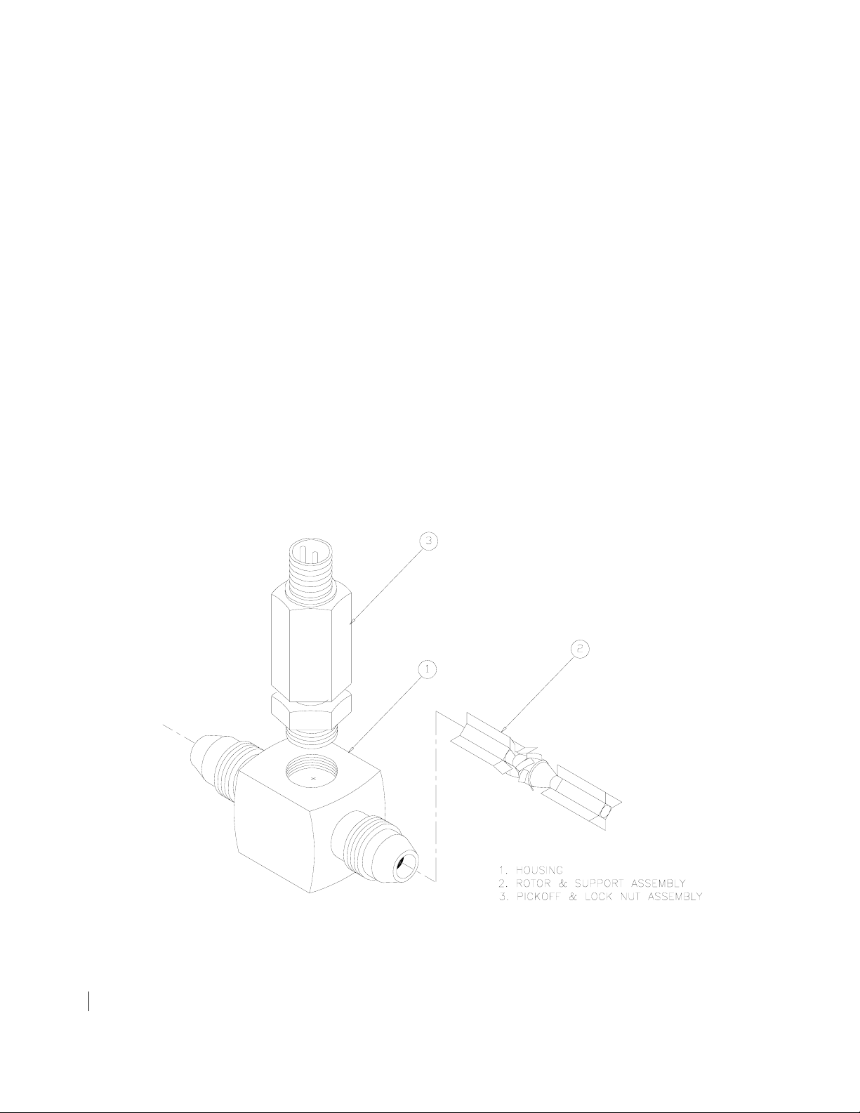
The Standard Line Flowmeter consists of 3 basic assemblies. (See Figure 1)
Figure 1. Flowmeter Basic Parts
TM-86675 1
Page 10
3.0 INSPECTION UPON RECEIPT
The flowmeter should be unpacked carefully and inspected to verify that no damage occurred during
shipment. Make certain that the internal parts are clean and free from packing materials or debris.
C A U T I O N
The flowmeter is a precision instrument and
may be damaged if pressurized air
is used for cleaning the flowmeter or for
checking the rotation of the rotor.
4.0 MECHANICAL CONNECTIONS
4.1 Flow Conditioning
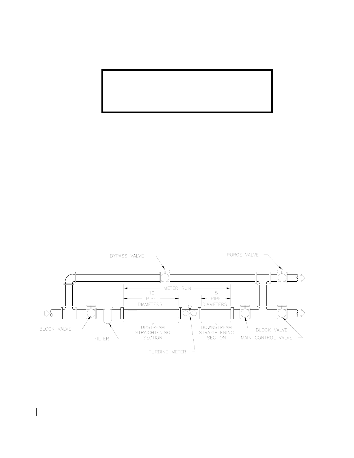
The turbine flowmeter is sensitive to velocity profile disturbances in the flow stream. For optimizing the
velocity profile it is recommended that a straight run of constant diameter piping with length of at least
10 diameters upstream of the meter and at least 5 diameters downstream be provided. (See Figure 2) The
upstream section should have straightening vanes or other flow conditioners. The presence of major
flow disturbance generators such as pumps, valves or elbows may require longer straight sections. If
swirl is present in the line ahead of the flowmeter installation, a longer straight section or additional
flow conditioning may be required. Flow Technology, Inc. provides an array of innovative state of the
art flow conditioners.
Figure 2. 3-Valve Bypass Manifold Pipe Schematic
TM-86675 2
Page 11

4.2 Flow Pulsations
Piping and system components should be arranged to minimize pulsations entering the turbine meter.
Pulsations may cause the meter to read high, and excessive pulsations may cause permanent bearing
damage. Pulsations should be kept below 10% of the current flow rate at the meter location.
C A U T I O N
Pressure should be built up gradually at start-up to avoid possible damage by
over-speeding the rotor. Any severe water hammering from improper start-up or
flow surges during operation must be avoided to prevent over-speeding, shaft or
rotor blade breakage.
NOTE
Water hammering is a term used during start-up (introducing fluid into the
piping) to describe a high velocity flow impact on the turbine rotor. This must be
avoided to prevent damage to the mechanical parts.
4.3 Purging
All flow lines in the meter system should be purged prior to installation of the meter. This will remove
pipe dope, metal shavings, slag and debris that may damage the turbine meter. Control valves should be
located downstream from the turbine meter. (See Figure 2) System start-ups with upstream control
valves in an unfilled system can result in a hydraulic shock on the meter, causing damage and a change
in calibration in liquid systems, or can cause over speed conditions in gas meter systems.
4.4 Installation Recommendation
For liquid flowmeters, it is recommended that the flowmeter be installed so that it remains full of fluid
when the flow ceases. When the flowmeter is left installed in a line that is temporarily out of service and
has been partially or fully drained, severe bearing corrosion may occur. The type and corrosiveness of
the fluid being metered, the type of bearing used in the flowmeter and the length of time the line will be
out of service are factors which may affect the life and operation of the flowmeters. If it is economically
feasible and conditions permit, the flowmeter should be removed, cleaned and stored when there is any
doubt about the fluid level in the line during these out-of-service periods. See section 10.1 inspection
cleaning and storage.
4.5 Orientation and Calibration
The orientation of the turbine flowmeter will influence the nature of the load on the rotor bearings, and
thus, the performance of the meter at low flow rates. For optimum accuracy a turbine meter should be
installed in the same orientation in which it was calibrated. Standard calibration orientation is with the
meter axis horizontal.
TM-86675 3
Page 12
4.6 Filtration
A filter should be installed upstream of the flowmeter. (See Figure 2) For 1/2 inch flowmeters, a 10
micron nominal filter should be used; for 3/4 inch and 1 inch flowmeters, a 20 micron nominal filter
should be installed; for flowmeters 1-1/2 inch in diameter or larger, a 50 micron filter is recommended.
4.7 Torque Requirements
The following table provides the recommended torques in pound-feet for tightening MS-33656 flaredtube end fittings:
TABLE 1
TORQUE REQUIREMENTS
POUND-FEET
SIZE ALUMINUM TUBING STEEL TUBING
MIN. MAX. MIN. MAX.
½” 19 21 37 40
5/8” 27 30 54 58
¾” 35 40 75 85
1” 41 58 100 116
1-1/4” 66 75 126 140
1-1/2” 66 75 158 175
2” 150 166 221 245
5.0 PICKOFFS
5.1 Installation
Pickoffs should bottom in the well of the flowmeter housing but should only be finger tightened to
approximately 4 lb-in (4500 gm-cm max) to prevent distortion of the coil housing. The pickoff is
secured in position by tightening the lock nut to approximately 25 lb-in (30000 gm-cm). The pickoff is
removed by loosening the hex lock nut and unscrewing the pickoff from the housing.
C A U T I O N
Meter pressure ratings are established with a pickoff
installed. Do not operate a flowmeter under pressure
without a pickoff installed.
5.2 Explosion Proof Housings
Flowmeters with explosion proof housings may have the pickoff installed inside a short section of
conduit pipe (spud) that is welded to the housing. Since the spud is longer than the pickoff, the pickoff
cannot be finger tightened directly and an alternate method must be used to install the pickoff. A
modified 11/16-inch deep socket is required to screw the pickoff into the housing and a modified 13/16inch deep socket is used to tighten the lock nut.
TM-86675 4
Page 13
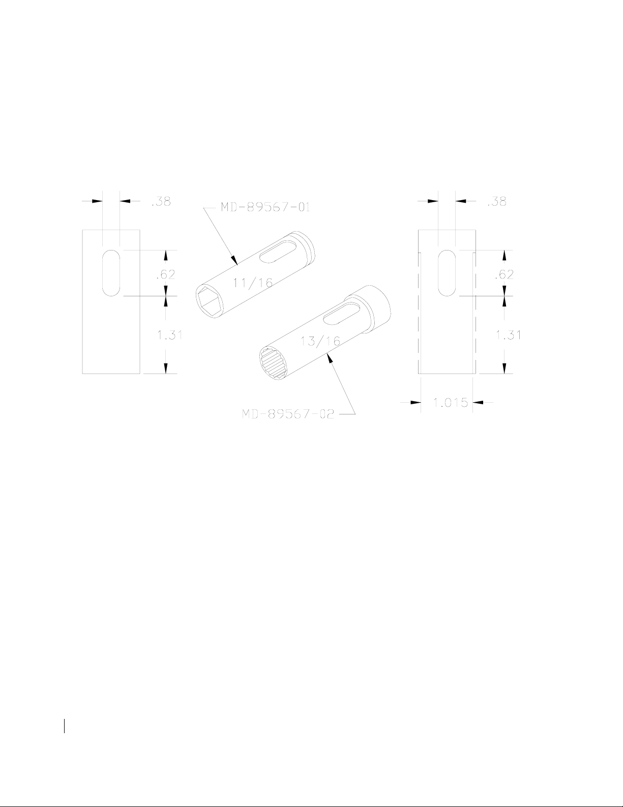
5.2.1 Pickoff Installation Sockets
Modify a standard 11/16-inch deep socket with an elongated 3/8-inch hole as shown in Figure 3. This
socket will fit the pickoff and allow easy feed through of the lead terminals without damaging the leads.
Modify a standard 13/16-inch deep socket with an elongated hole. (See Figure 3) Cut the outside
diameter of the socket to 1.015 inches as shown to permit the socket to tighten the lock nut inside the
conduit without damaging the pickoff leads.
Figure 3. Pickoff Installation Sockets
5.3 Magnetic Pickoff
The magnetic pickoff output is a low level signal that ranges from 10 mV to several volts peak-to-peak.
A pulse amplifier may be needed to convert the pickoff low level signal to a 10 V peak-to-peak pulse
signal suitable for process instrumentation. Typical resistance of magnetic pickoffs are 2275 Ω ± 20%.
5.4 RF Pickoff
The modulated carrier (RF) pickoff must be installed with an appropriate amplifier (consult factory).
The amplifier is needed to convert the modulated carrier signal to a 10 V peak-to-peak pulse signal
suitable for process instrumentation. Typical resistance of modulated carrier pickoffs is 10 Ω ± 10%.
TM-86675 5
Page 14

6.0 ELECTRICAL CONNECTIONS
6.1 Connections
Standard pickoffs are available with a two-contact type MS3102A-10SL-4P connector or with threaded
body and pigtail connectors.
6.2 Connection Cable
The connecting cable between the flowmeter and the electronic instrumentation should be a two
conductor, 22 AWG, shielded and twisted cable with a vinyl jacket (Belden 8761 or equivalent). The
cable should not be installed in a conduit or tray containing power lines, or close to strong
electromagnetic sources such as electric lines, electric motors, transformers, welding machines, or high
voltage lines. These sources may induce transient electrical noise in the coil and cause false pulse
signals. Connections from standard pickoffs are not polarized and may be connected in either position.
For non-standard pickoffs please refer to manufacturer's specifications.
6.3 Grounding Considerations
The shield of the cable is to be grounded at only one point in accordance with the instruction of the
display instrument. Flow Technology, Inc. display instruments specify where the shield is to be
grounded.
TM-86675 6
Page 15

6.4 Signal Processing
An electronic signal conditioning circuit is required to either convert the frequency output of the
flowmeter into a visual presentation on a display or to provide process control signals. Flow
Technology, Inc. manufactures a complete line of electronic packages, which include rate and total
displays, rate converters and microprocessor based units for linearization and temperature / pressure
compensation.
Pickoff Connector Specifications
Standard 2 Pin MS Non-polarized Pins
27-31386 3 Pin MS Pins: A = Coil B = Coil C = N/C
Inductance = 0.350 mh ± 10 % Resistance = 3.5 ohms ± 10 %
Amplified Pickoffs
27-94057
Pick-off w/RTD
RF 27-62730
Mag 27-62731
3 Pin MS
Wire Leads
4 Pin MS
Wire Leads
Pins: A = Power B = Ground C = Pulse
Red = Power Black = Ground White = Pulse
Input Power = 8 to 32 VDC @ 10 ma
Output = 0 to 5 VDC Pulse
Output Impedance = 2.2 K ohms
Mag Amp: Frequency Range = 10 Hz to 10 KHz
Input Sensitivity = 20 MV p-p
RF Amp: Frequency Range = 10 to 3200 Hz
Oscillator Carrier Frequency = 45 KHz
Pins: A=Coil B=Coil Non-polarized
C= RTD high D= RTD low & RTD compensation
Leads: White= Coil Non-polarized
Red= RTD high Black= RTD low & RTD compensation
RTD= 100 Ohm Platinum
7.0 BIDIRECTIONAL FLOWMETERS
Turbine flowmeters can be configured to measure flow in both directions and provide direction-sensing
capability. This is accomplished by adding a second pickoff located with respect to the first pickoff in
such a way as to achieve a 90-phase shift. The location of the pickoffs are determined by the number of
blades on the rotor.
TM-86675 7
Page 16

8.0 OPERATION
8.1 Over Range
In general, turbine flowmeters remain quite linear when they are over ranged, and may not provide any
indication that the instrument is being misused. However, the pressure drop will become excessive and
over speeding of the bearings could cause permanent damage. Bearings may also be damaged by
excessive downstream thrust load. The probability of an over speed condition for a liquid meter usually
occurs during system start up when there is still air in the lines. Air should be bled carefully from the
lines before high flow range is established. The flow rate or output frequency should be monitored to
insure maximum capability is not exceeded. Flow Technologies’s specifications should be consulted for
specific maximum operating flow rates. See tables 4,5,6 and 7. Under extreme conditions, the maximum
operating flow rates can be exceeded for brief periods of time without meter damage. Following are the
maximum allowable over range capabilities:
Bearing Type Liquid Gas
Ball 50% 10%
Pivot 10% 10%
Journal 50% N/A
8.2 Under Range
When used below the minimum specified range, turbine meters may become very non-linear. The
repeatability of the meter may also be reduced due to bearing and magnetic pickoff drag.
8.3 Liquid Turbine Flowmeter Characteristics
8.3.1 Introduction
Optimum performance of a turbine meter system depends upon a valid calibration as well as the correct
selection of supporting equipment. The rotational speed of a turbine rotor depends upon fluid properties
as well as the fluid velocity. The most significant fluid property for a liquid meter is the kinematic
viscosity. As liquid viscosity increases, the slip of the turbine rotor due to viscous drag is increased, and
the rotational speed and hence pick-off frequency is decreased. Due to these effects, the kinematic
viscosity of the calibration fluid should approximate the service conditions as closely as possible.
8.3.2 Standard Calibration
Standard liquid calibrations at FTI are done with MIL-C-7024 Type II solvent or water at room
temperature. The viscosity of these fluids is approximately 1.25 and 1 centistokes respectively. The
standard calibration consists of 10 data points distributed over the normal 10:1 range of the flowmeter.
If viscosities or flow ranges other than these are required, they must be specified.
TM-86675 8
Page 17

8.3.3 Single Viscosity Calibration
If the flowmeter is to be used at a viscosity other than the standard calibration viscosities, an oil blend
calibration should be done on the meter to simulate the operating conditions. The calibration curve
produced will represent the flowmeter’s output characteristics for that specific viscosity. If the
flowmeter is used with liquids having viscosities greater than 3 centistokes, the linearity of the K-factor
will be reduced.
8.3.4 Multiple Viscosity Calibrations
If the viscosity is changing due to varying temperature in the system, the performance characteristics
over a range the viscosities can be established. This is done by performing multiple calibrations at
different viscosities to cover the range of interest. The K-factor of the meter is then plotted as a function
of Hz/v. The K-factor is the number of pulses generated by a flowmeter for every unit volume of fluid
passing through it. Hz is the output frequency of the meter and v is the kinematic viscosity of the fluid in
centistokes. The plot of K vs. Hz/v is commonly referred to as a universal viscosity curve. The data is
plotted in this manner because all points fall on a single smooth curve. To obtain a useful curve,
calibration points for calibrations at several viscosities are required. By observing the output frequency
of the flowmeter and obtaining the viscosity or temperature of the fluid, the value of Hz/v can be
calculated. Using the universal viscosity curve, the value of K corresponding to the known value of Hz/v
can be determined. With the K-factor known, the flow through the meter can be determined from the
expression:
Hz (60)
GPM =
K - factor
8.4 Gas Turbine Flowmeter Characteristics
8.4.1 Introduction
Accurate performance of gas turbine flowmeters depend on a valid calibration that simulates the
conditions the meter will operate in. Changes in the pressure and temperature of a gas directly affect the
density and kinematic viscosity of the fluid. These changing fluid properties affect the performance of
gas flowmeters in much the same way as liquid flowmeters.
TM-86675 9
Page 18

Due to the nature of gasses to be compressed, the volume of gas measured is dependent on the pressure
and temperature as established by Boyle's Law and Charles' Law. Using these relationships, the actual
volume of gas measured can be related to a standard set of conditions that provide useful technical data.
The standard conditions for pressure and temperature used at Flow Technology, Inc. are 14.7 pounds per
square inch absolute (PSIA) and 520 degrees Rankine (60 degrees Fahrenheit) respectively. For proper
conversions, the absolute measurement for pressure and temperature must be used.
The following equation is used to convert the actual volumetric flow rate (QA) in Actual Cubic Feet per
Minute (ACFM) to the equivalent standard flow rate (QS) in Standard Cubic Feet per Minute (SCFM).
P
Q
= Q A ( ---- ) ( ---- )
S
P
T S
A
T A
S
Where:
QS = Standard flow rate in SCFM
QA = Actual measured flow rate in ACFM
PA = Actual measured pressure at pressure tap on meter (PSIA)
PS = Standard Pressure (14.7 PSIA)
TA = Actual measured temperature downstream of meter ( R)
TS = Standard temperature (520 R)
8.4.2 Air Calibration
Gas calibrations at FTI are done using air at ambient conditions. These conditions are typically 14.2
PSIA and 72 F. The standard calibration consists of 10 data points distributed over the normal 10:1
range of the flowmeter. If conditions or flow ranges other than these are required, they must be
specified.
8.4.3 Single Pressure Calibrations
If the flowmeter is to be used at conditions that vary significantly from the standard calibration, a
calibration at equivalent conditions should be performed to simulate the actual operating conditions.
The calibration curve produced will represent the flowmeter's output characteristics for the specified gas
at the actual operating conditions.
TM-86675 10
Page 19

8.4.4 Multiple Pressure Calibrations
Performance characteristics over a range of pressures can be established for operating conditions where
the temperature and pressure are changing. This is done by performing multiple calibrations at different
pressures to cover the range of interest. The information obtained is then plotted on a curve of K-factor
verses Hz/v where the K-factor is the pulses per unit volume generated by the flowmeter and the Hz/v is
the frequency output of the flowmeter divided by the kinematic viscosity of the fluid. The procedure is
similar to liquid meters using the universal viscosity curve. By reading the output frequency of the
flowmeter during operation and dividing it by the kinematic viscosity of the fluid being used, the
volumetric flow rate can be determined by reading the K-factor from the universal viscosity curve and
calculating the flow rate:
Hz (60)
CFM =
K - factor
Electronic instrumentation is available that can be programmed with the universal viscosity curve and
setup with pressure and temperature transducers that will automatically make these calculations and read
out the corrected flow rate.
9.0 SPECIFICATIONS AND OPTIONS
Table 2 shows the complete model numbering system for the FT series flowmeters. The sections that
follow describe the contents of Table 2 in detail.
Tables 3 thru 7 describe the different bearings and their applications.
TM-86675 11
Page 20

TABLE 2
FT MODEL NUMBERING SYSTEM
FT _ _ _ _ _ _ _ _ _ _ __ _ _ _ _ _
BASE MODEL
2-8 Through 192
( 1/2" Through 12" )
END FITTINGS
Refer to Section 9.1
CALIBRATION
Refer to Section 9.2
NON STANDARD UNITS
U = To signify required units of measure
other than GPM or ACFM
R = To signify special calibration flow range
other than normal 10:1 or extended range
B = to signify both changes in units and
special flow range
SERVICE
L = Liquid
G = Gas
P = Gas with pressure tap
CONSTRUCTION MATERIALS
Refer to Section 9.3
BEARINGS
A = Ball Bearing
D = Carbide Journal
E = Graphite Journal
G = Ceramic Journal
H = Ball Bearing Self Lubricating (FT64 & smaller gas meters)
Refer to Section 9.4
PICKOFFS
Refer to Section 9.5
SPECIAL CODE
Special meter configurations will not be addressed in this manual
please contact the factory for a description of the special code.
TM-86675 12
Page 21

9.1 End Fittings
AE = AN (or MS) external straight
BE = British Standard external pipe threads 1/2" to 4"
NE = NPT external threads, 1/2" to 6"
HB = Hose Barb
WF = Wafer type serrated surface
C1 = 150# Raised Face Flange
C2 = 300# Raised Face Flange
C3 = 600# Raised Face Flange
C4 = 900# Raised Face Flange
C5 = 1500# Raised Face Flange
C6 = 2500# Raised Face Flange
J1 = 150# Ring Joint Flange
J2 = 300# Ring Joint Flange
J3 = 600# Ring Joint Flange
J4 = 900# Ring Joint Flange
J5 = 1500# Ring Joint Flange
J6 = 2500# Ring Joint Flange
D1 = DIN Flange PN16
D2 = DIN Flange PN40
D3 = DIN Flange PN100
D4 = DIN Flange PN160
D5 = DIN Flange PN250
D6 = DIN Flange PN400
9.2 Calibration
KA = 3 Point, K-factor average, in Air
KW = 3 Point, K-factor average, in Water
KS = 3 Point, K-factor average, in Solvent
KB = 3 Point, K-factor average, in Oil Blend
NA = 10 Point, normal 10:1 range, in Air
NW = 10 Point, normal 10:1 range, in Water
NS = 10 Point, normal 10:1 range, in Solvent
NB = 10 Point, normal 10:1 range, in Oil blend
XA = 10 Point, extended range, in Air
XW = 10 Point, extended range, in Water
XS = 10 Point, extended range, in Solvent
XB = 10 Point, extended range, in Oil blend
TA = 20 Point, normal 10:1 range, in Air
TW = 20 Point, normal 10:1 range, in Water
TS = 20 Point, normal 10:1 range, in Solvent
TB = 20 Point, normal 10:1 range, in Oil blend
YA = 20 Point, extended range, in Air
YW = 20 Point, extended range, in Water
TM-86675 13
Page 22

YS = 20 Point, extended range, in Solvent
YB = 20 Point, extended range, in Oil blend
GA = 30 Point, extended range, in Air
GW = 30 Point, extended range, in Water
GS = 30 Point, extended range, in Solvent
GB = 30 Point, extended range, in Oil blend
U2 = Universal Viscosity Curve, 2 viscosities
U3 = Universal Viscosity Curve, 3 viscosities
R1 = Reynolds # Calibration, 10 Point 1 Pressure
R2 = Reynolds # Calibration, 10 Point 2 Pressure
R3 = Reynolds # Calibration, 10 Point 3 Pressure
E1 = Reynolds # Calibration, 20 Point 1 Pressure
E2 = Reynolds # Calibration, 20 Point 2 Pressure
E3 = Reynolds # Calibration, 20 Point 3 Pressure
LW = 10 Point 10:1 Range, in Water, Premium linearity
LS = 10 Point 10:1 Range, in Solvent, Premium linearity
BA = Bidirectional, 1 Pickoff, 10 points each direction, Air
BW = Bidirectional, 1 Pickoff, 10 points each direction, Water
BS = Bidirectional, 1 Pickoff, 10 points each direction, Solvent
BB = Bidirectional, 1 Pickoff, 10 points each direction, Oil blend
CA = Bidirectional, 2 Pickoff, 10 points each direction, Air
CW = Bidirectional, 2 Pickoff, 10 points each direction, Water
CS = Bidirectional, 2 Pickoff, 10 points each direction, Solvent
CB = Bidirectional, 2 Pickoff, 10 points each direction, Oil blend
9.3 Construction Materials
C = 304 Housing, 430F Rotor
D = 304 Housing, 17-4 Rotor
E = 316 Housing, 430F Rotor
G = 316 Housing, 316 Rotor
H = 316 Housing, 17-4 Rotor
N = Hast C Housing, Hast C Rotor
Q = PVC Housing, PVC Rotor
R = Monel 400 Housing, Monel 400 Rotor
T = Carp 20 Housing, Carp 20 Rotor
9.4 Bearing Code
A = 440C Ball Bearings.
D = Carbide Journal - Carbide Shaft and Bearing.
E = Graphite Journal - 316 SST Shaft and Graphite Bearing
G = Ceramic Journal - Ceramic Shaft and Bearings
H = 440C Ball Bearings. (Polymer retainer )
TM-86675 14
Page 23

Table 3
BEARING APPLICATION GUIDE
CODE BEARING TYPE SERVICE BEARING
TEMPERATURE
RATING
A BALL LIQUID OR GAS -450° F TO 300° F 440C SST
MATERIAL
D CARBIDE
JOURNAL
E GRAPHITE
JOURNAL
G CERAMIC
JOURNAL
H BALL LIQUID OR GAS -450° F TO 300° F 440C SST POLYMER
LIQUID UP TO 1200° F C-2 CARBIDE
LIQUID UP TO 500° F 316 SHAFT GRAPH. BRG.
LIQUID UP TO 1200° F ALUMINUM BASED
CERAMIC
RETAINER
Meter temperature rating may be limited by the pickoff temperature rating
9.5 Pickoffs
-1 = RF MS Connector 400 ° F, 27-31199-101
-2 = MAG MS connector 400° F, 27-30880-101
-3 = MAG Explosion Proof 400° F, 27-30880-102 leads / 27-30931-102 EP
-5 = RF Explosion Proof 400° F, 27-31199-102 leads / 27-31949-101 EP
-6 = MAG MS connector 750°F, 27-80666-104
-7 = MAG Explosion Proof 750° F, 27-80666-104 MS / 27-82333-102 EP
-8 = RF MS Cox Equivalent 400° F, 27-84097-102
-9 = RF MS 5/8 Thd. 400° F, 27-84097-101
S8 = RF F & P 400° F, 27-31386-101
-L = RF MS connector 750° F, 27-88628-102
-M = RF Explosion Proof 750° F, 27-88826-103
-Y = RF Explosion Proof (CSA) 400° F, 27-13869-101
-Z = MAG Explosion Proof (CSA) 400° F, 27-13868-101
-U = MAG MS (Factory Mutual) 400° F, 27-32400-101
-X = RF MS (Factory Mutual) 300° F, 27-32404-101
PP = MAG Leads (Factory Mutual) 400
° F, 27-32400-103
SS = RF Leads (Factory Mutual 300° F, 27-32404-103
TT = MAG Explosion Proof (Factory Mutual) 400° F, 27-32400-102
XX = RF Explosion Proof (Factory Mutual) 300
A1 = RF MS Amplified 230
° F, 27-61313-104
° F, 27-32404-102
A2 = MAG MS Amplified 230° F, 27-61313-101
A3 = MAG Explosion Proof 230
° F, 27-61313-102
A4 = MAG Leads Amplified 230° F, 27-61313-103
A5 = RF Explosion Proof Amplified 230
A6 = RF Leads Amplified 230
° F, 27-61313-106
° F, 27-61313-105
TM-86675 15
Page 24

TABLE 4
LIQUID SERVICE - BALL BEARING
MODEL
FT4-8 .25-2.5 .03-3 .1-3 48000 2000
FT6-8 .5-5 .05-5 .12-5 25000 2100
FT8-8 .75-7.5 .08-8 .16-8 16000 2000
FT-08 1-10 .1-10 .2-10 12000 2000
FT-10 1.25 - 12.5 .15-15 .3-15 9600 2000
FT-12 2-20 .25-25 .5-25 5400 1800
FT-16 5-50 .6-60 1-60 2400 2000
FT-20 9-90 1-100 1-100 1300 1950
STD RANGE
10:1 (GPM)
RF & MAG
PICKOFF
EXTENDED
RANGE
(GPM)
RF
PICKOFF
EXTENDED
RANGE
(GPM)
MAG
PICKOFF
NOMINAL
K FACTOR
PULSE/
GALLON
MAX
FREQ.
(HZ)
FT-24 15-150 1.6-160 2.5-160 600 1500
FT-32 22-225 2.5-250 3.5-250 350 1300
FT-40 40-400 4.5-450 5.0-450 180 1200
FT-48 65-650 N/A 7.5-750 75 812
FT-64 125-1250 N/A 15-1500 30 625
FT-96 300-3000 N/A 50-3500 28 1400
FT128 550-5500 N/A 60-6000 14 1300
FT160 850-8500 N/A 100-10000 8.5 1200
FT192 1200-12000 N/A 1500-15000 5.0 1000
Notes:
1. Repeatability
2. Linearity = ± .5% of reading except as noted. Values are valid for viscosities of 3 centistokes or less
based on standard 10:1 range.
3. RF Pickoff not applicable for meter sizes FT-48 and larger.
4. Linearity = ± .75% of reading for FT4-8 and FT6-8 when high temp mag pickoff is used.
5. Premium linearity available over select ranges consult factory.
= ± .05%
TM-86675 16
Page 25

TABLE 5
LIQUID SERVICE - JOURNAL BEARING
MODEL
FT4-8 .25-2.5 .1-3.0 .12-3.0 48000 2000
FT6-8 .5-5.0 .15-5.0 .2-5.0 25000 2000
FT8-8 .75-7.5 .2-8.0 .25-8.0 16000 2000
FT-08 1.0-10.0 .25-10 .3-10 12000 2000
FT-10 1.25 - 12.5 .3-15 .4-15 9600 2000
FT-12 2-20 .5-25 .5-25 6000 2000
FT-16 5-50 1.0-60 1.0-60 2400 2000
FT-20 9-90 1.0-100 1.5-100 1300 1950
STD RANGE
10:1 (GPM)
RF & MAG
PICKOFF
EXTENDED
RANGE
(GPM)
RF
PICKOFF
EXTENDED
RANGE
(GPM)
MAG
PICKOFF
NOMINAL
K FACTOR
PULSE/
GALLON
MAX
FREQ.
(HZ)
FT-24 15-150 1.6-160 2.5-160 600 1500
FT-32 22-220 2.5-250 3.5-250 350 1300
FT-40 40-400 4.5-450 5.0-450 180 1200
FT-48 65-650 N/A 7.5-750 75 812
FT-64 125-1250 N/A 15-1500 30 625
FT-96 300-3000 N/A 50-3500 28 1400
FT128 550-5500 N/A 60-6000 14 1300
FT160 850-8500 N/A 100-10000 8.5 1200
FT192 1200-12000 N/A 150-15000 5.0 1000
Notes:
1. Repeatability = +/- .1% for FT-12 and smaller, +/- .05% for FT-16 and larger.
2. Linearity = +/- .5% of reading except as noted.
Values are valid for viscosities of 3 centistokes or less based upon standard 10:1 range.
3. Linearity is +/- 2% of reading for FT4-8.
4. Linearity is +/- .75% of reading for FT6-8 when high temp mag pickoff is used
5. Premium linearity available over select ranges consult factory.
6. RF pickoff not applicable for meter sizes FT-48 and larger.
TM-86675 17
Page 26

TABLE 6
GAS SERVICE - BALL BEARING “H” CODE
MODEL
FT2-8 .1-1.0 .09-1.25 N/A 114000 1900
FT4-8 .25-2.5 .2-3.0 N/A 40800 1700
FT6-8 .5-5.0 .25-5.0 .4-5.0 24000 2000
FT8-8 .75-7.5 .4-8.0 .5-8.0 16000 2000
FT-08 1.0-10.0 .5-10 .75-10 12000 2000
FT-10 1.25 - 12.5 .6-15 1-15 9600 2000
FT-12 2-20 1-25 1.5-25 6000 2000
FT-16 5-50 1.5-60 2.5-60 2400 2000
STD RANGE
10:1 (ACFM)
RF & MAG
PICKOFF
EXTENDED
RANGE
(ACFM)
RF
PICKOFF
EXTENDED
RANGE
(ACFM)
MAG
PICKOFF
NOMINAL
K FACTOR
PULSE / ACF
MAX
FREQ.
(HZ)
FT-20 9-90 2.5-100 5-100 1300 1950
FT-24 15-150 4-160 6-160 600 1500
FT-32 22-220 5-250 8-250 350 1300
FT-40 40-400 9-450 10-450 180 1200
FT-48 65-650 N/A 15-750 75 812
FT-64 125-1250 N/A 30-1500 30 625
Notes:
1. Gas service - Air @ 14.7 PSIA and 60 F.
2. Repeatability = +/- .1%.
3. Linearity = +/- 1.0% of full scale based on standard 10:1 range.
4. MAG Pickoff not applicable for FT2-8.
5. MAG Pickoff range is .35 - 2.5 ACFM for FT4-8.
6. Linearity for FT2-8 is 4% of full scale, repeatability is +/- .5%.
7. Linearity for FT4-8 is 3% of full scale, repeatability is +/- .3%.
8. Linearity for FT6-8 is 1.5% of full scale, repeatability is +/- .15%.
9. RF Pickoff not applicable for meter sizes FT-48 and larger.
TM-86675 18
Page 27

TABLE 7
GAS SERVICE - BALL BEARING “A” CODE
MODEL
FT2-8 .1-1.0 .09-1.25 N/A 93000 1550
FT4-8 .25-2.5 .2-3.0 N/A 45000 2000
FT6-8 .5-5.0 .25-5.0 .4-5.0 24000 2000
FT8-8 .75-7.5 .4-8.0 .5-8.0 16000 2000
FT-08 1.0-10.0 .5-10 .75-10 12000 2000
FT-10 1.25 - 12.5 .6-15 1-15 9600 2000
FT-12 2-20 1-25 1.5-25 6000 2000
FT-16 5-50 1.5-60 2.5-60 2400 2000
STD RANGE
10:1 (ACFM)
RF & MAG
PICKOFF
EXTENDED
RANGE
(ACFM)
RF
PICKOFF
EXTENDED
RANGE
(ACFM)
MAG
PICKOFF
NOMINAL
K FACTOR
PULSE / ACF
MAX
FREQ.
(HZ)
FT-20 9-90 2.5-100 5-100 1300 1950
FT-24 15-150 4-160 6-160 600 1500
FT-32 22-220 5-250 8-250 350 1300
FT-40 40-400 9-450 10-450 180 1200
FT-48 65-650 N/A 15-750 75 812
FT-64 125-1250 N/A 30-1500 30 625
FT-96 300-3000 N/A 70-3500 9.0 467
FT128 550-5500 N/A 120-6000 4.0 325
FT160 850-8500 N/A 200-10000 2.0 240
FT192 1200-12000 N/A 300-15000 1.0 167
Notes:
1. Gas service - Air @ 14.7 PSIA and 60 F.
2. Repeatability = +/- .1%.
3. Linearity = +/- 1.0% of full scale based on standard 10:1 range.
4. MAG Pickoff not applicable for FT2-8.
5. MAG Pickoff range is .35 - 2.5 ACFM for FT4-8.
6. Linearity for FT2-8 is 4% of full scale.
7. RF Pickoff not applicable for meter sizes FT-48 and larger.
TM-86675 19
Page 28

NOTE: 1” NPT enclosure connection is standard on FT-16
and larger wafer meters. Meters smaller than FT-16 will
have pickoff connection only.
Figure 1
MODEL
NO.
PREFIX
FT2-8
FT4-8
FT6-8
FT8-8
FT-08
FT-10
FT-12
FT-16
FT-20
FT-24
FT-32
FT-40
FT-48
FT-64
FT-96
FT128
FT160
FT192
NOMINAL
END
FITTING
(INCH)
½
½
½
½
½
¾
¾
1
1 ¼
1 ½
2
2 ½
3
4
6
8
10
12
150 #
A B
5.00
5.00
5.00
5.00
5.00
5.50
5.50
5.50
6.00
6.00
6.50
7.00
10.00
12.00
14.00
16.00
20.00
24.00
Figure 4. Dimensions
WAFER – STANDARD LINE
MODEL
NO.PREFIX
NOMINAL END
FITTING (INCH)
A B
FT2-8 1/2 1.88 1.38
FT4-8 1/2 1.88 1.38
FT6-8 1/2 1.88 1.38
FT8-8 1/2 1.88 1.38
FT-08 1/2 1.88 1.38
FT-10 3/4 1.94 1.69
FT-12 3/4 1.94 1.69
FT-16 1 2.50 2.00
FT-20 1 1/4 2.50 2.50
FT-24 1 1/2 2.50 2.88
FT-32 2 3.00 3.63
FT-40 2 1/2 5.25 4.13
FT-48 3 5.75 5.00
FT-64 4 5.00 6.18
FT-96 6 6.13 8.50
3.50
3.50
3.50
3.50
3.50
3.88
3.88
4.25
4.63
5.00
6.00
7.00
7.50
9.00
11.00
13.50
16.00
19.00
300 #
A B
5.00
3.75
5.00
3.75
5.00
3.75
5.00
3.75
5.00
3.75
5.50
4.63
5.50
4.63
5.50
4.88
6.00
5.25
6.00
6.13
6.50
6.50
7.00
7.50
10.00
8.25
12.00
10.00
14.00
12.50
16.00
15.00
20.00
17.50
24.00
20.50
600 #
A B
5.00
3.75
5.00
3.75
5.00
3.75
5.00
3.75
5.00
3.75
5.50
4.63
5.50
4.63
5.50
4.88
6.00
5.25
6.00
6.13
6.50
6.50
9.00
7.50
10.00
8.25
12.00
10.75
14.00
14.00
16.00
16.50
20.00
20.00
24.00
22.00
900 #
A B
7.00
4.75
7.00
4.75
7.00
4.75
7.00
4.75
7.00
4.75
5.50
5.13
7.00
5.13
8.00
5.88
8.00
6.25
9.00
7.00
9.00
8.50
9.00
9.63
10.00
9.50
12.00
11.50
14.00
15.00
16.00
18.50
20.00
21.50
24.00
24.00
1500 #
A B
7.00
4.75
7.00
4.75
7.00
4.75
7.00
4.75
7.00
4.75
5.50
5.13
7.00
5.13
8.00
5.88
8.00
6.25
9.00
7.00
9.00
8.50
9.00
9.63
10.00
10.50
12.00
12.25
14.00
15.50
16.00
19.00
20.00
23.00
24.00
26.50
2500 #
A B
7.00
5.25
7.00
5.25
7.00
5.25
7.00
5.25
7.00
5.25
7.00
5.50
7.00
5.50
8.00
6.25
8.00
7.25
9.00
8.00
9.00
9.25
10.00
10.50
10.00
12.00
12.25
14.00
14.00
19.00
16.00
21.75
20.00
26.50
24.00
30.00
TM-86675 20
Page 29

10.0 PERIODIC MAINTENANCE
Maintenance of the Standard Line Flowmeter consists of periodic inspections to insure that the internal
parts have not suffered any corrosion or incrustation by measuring fluid. Should the assembly be
damaged, it should be returned to the factory for exchange or repair.
10.1 Inspection Cleaning and Storage
For inspection and cleaning of internal parts, the rotor and support assembly may be withdrawn from the
housing. The rotor support assembly and the housing may be cleaned with appropriate solvent or
alcohol. If liquid flowmeters are to be stored or out of service for an extended period, it should be
dipped in a light rust proofing preservative or machine oil and capped. Gas flowmeters should be
cleaned and capped to prevent dust or foreign materials.
C A U T I O N
Service for some fluids may require special
cleaning procedures before installation.
Please consult fluid manufacturer and/or
use industry accepted procedures.
One of the largest single sources of poor turbine meter performance is foreign material buildup on
bearings whether they are journal type or ball type. It is recommended that whenever possible, the
turbine meter be thoroughly flushed with an appropriate solvent immediately after use. The solvent
should be chemically neutral, and highly volatile so that complete drying can take place soon after the
flushing operation. Some appropriate solvents would be ethyl alcohol or stoddard solvent.
All turbine flowmeters include some type of bearing for supporting its rotor. The standard line
flowmeter is normally equipped with ball bearings, but journal bearings fabricated of tungsten carbide,
ceramic, epoxy impregnated graphite and other non-metallic materials are also available. If the bearings
in the flowmeter become damaged or worn, the meter should be sent to the factory for bearing
replacement. If this is not possible, a bearing replacement kit is available for most models. All bearings
are not field replaceable. Consult the factory and describe the particular flowmeter before ordering a
bearing replacement kit.
TM-86675 21
Page 30

10.2 Removing Internals
There are several variations of the basic turbine flowmeter design. This section will explain the general
procedure for disassembling Flow Technology, Inc. turbine flowmeters. Refer to the following sections
for detailed instructions on disassembly of specific flowmeters.
CAUTION
Observe flow direction markings carefully. Some of the internal parts are symmetrical
and may fit and function forward and reverse. The calibration will shift due to variations
in the rotor blade edges and the degree of bend in the support trim tabs if installed
incorrectly.
Before removing the housing retaining ring note the orientation of the retaining ring, the
hook on the retaining ring prevents the support/spacer from spinning.
1. Familiarize yourself with the figure applicable to your model before proceeding.
2. Remove the upstream retaining ring, note the orientation.
3. Insert a plastic rod into the downstream end of the meter and gently press against the
downstream support. Select a large enough rod so that it cannot accidentally slip past
the support vanes and impact the rotor. Gently slide the internal assembly out of the
housing being careful not to drop any of the internal parts as they clear the housing.
Maintain compression between the supports to insure that the internals remain
assembled until you have noted the flow direction markings on the supports and the
rotor.
4. Locate the flow direction of the supports and the rotor. The downstream side of the
rotor will have two small marks which are typically hand scribed on the hub. If the
marks are not clear, remark the rotor to assure correct re-assembly. If you use a
marking pen or pencil, be aware that your markings may be removed during cleaning.
5. Spin the rotor slowly, and note any signs of scoring, wobble, damaged or bent blades.
Replace the rotor if it shows any signs of damage.
Important: Do not straighten the tabs
are trim tabs used to improve meter performance. Altering the tab angle will
cause a shift in the K-factor.
6. Clean or replace parts as necessary.
7. Reverse procedure to reinstall. Insure that the flow direction arrow on the internals
match the flow direction arrow on the housing when the internals are reinstalled.
on the support adjacent to the rotor. These
TM-86675 22
Page 31

10.3 General Handling Techniques
1. All work with bearings should be done in a clean, dry, dust and static free area.
2. Consider all foreign materials to be abrasive, corrosive or otherwise destructive.
3. Verify that the shaft and rotor have been cleaned and are free of oil, contamination and
burrs.
4. Keep all bearings in their original unopened packages until ready for installation.
Remove the bearings from their protective packages one at a time, as required.
5. The bearings should be handled with tweezers or other special non-magnetic tools.
6. Never touch high precision bearings with fingers unprotected by finger cots or lint free
gloves.
7. Seat the bearing squarely and apply even pressure to the race making contact. ( See
Figure 5 )
8. When installing a bearing in the rotor apply pressure to the outer race.
9. When installing a bearing onto a shaft, apply pressure to the inner race.
10. Never transfer force between the outer and inner races, or damage could result and
cause increased friction, increased torque, and shortened bearing life.
11. Shock or impact techniques
should never be used to seat
the bearing.
12. Installing the small retaining
rings requires a quality pair
of sharp tweezers and good
dexterity. The bearing
retaining rings are under
spring tension and can easily
shoot out while removing or
installing. Wear eye
protection.
Figure 5. Bearing Seating
TM-86675 23
Page 32

10.4 Ball Bearing Replacement
Ball bearings may be replaced in the field by the customer without significantly changing the flowmeter
performance, provided the downstream orientation of the rotor is maintained. Complete replacement sets
of calibrated internals are also available.
10.4.1 Ball Bearing Replacement For:
Liquid Models: FT4-8
Gas Models Bearing Code H: FT-10; FT-12
Refer to Figures 7, 11
1. Remove the retaining ring (2) from either end of the flowmeter housing, note the orientation.
2. Gently slide the flowmeter rotor support assembly out of the housing, being careful
not to drop any of the internal parts as they clear the housing.
3. Remove the downstream support (6) and the cone (7A) from the shaft (7B). Note on
the FT4-8 flanged meters there is an upstream and downstream spacer (8) between the
support (6) and the retaining ring (2).
4. Note that the rotor (7C) is marked on the downstream side with two lines on the rotor
hub.
5. Gently slide the rotor assembly from the shaft (7B).
6. Slide both bearings (10) and the bearing spacer (11) out of the rotor hub (7C).
7. Verify the retaining ring (9) is in good condition and seated in the center of the rotor.
8. Reverse steps 1 through 5 for re-assembly. Insure the flow direction arrow on the
internals match the flow direction arrow on the housing when the internals are
reinstalled. Insure the rotor (7C) is properly oriented with markings on the
downstream side.
TM-86675 24
Page 33

10.4.2 Ball Bearing Replacement For:
Liquid Models FT6-8; FT8-8; FT-08; FT-10; FT-12; FT-16; FT-20; FT-24
Gas Models
Bearing Code A & H:
Gas Models
Bearing Code A:
Refer to Figure 7, 8, 9, 10 & 12
1. Remove the retaining ring (2) from either end of the flowmeter housing, note the orientation.
2. Gently slide the flowmeter rotor support assembly out of the housing, being careful
not to drop any of the internal parts as they clear the housing.
3. Remove the downstream support (6) and cone (7A) from the shaft (7B). Note on the
flanged FT2-8 thru FT-08 meters there is an upstream and downstream spacer (8)
between the support (6) and the retaining ring (2).
4. Note that the rotor (7C) is marked on the downstream side with two lines on the rotor
hub.
5. Gently slide the rotor assembly from the shaft.
6. Remove the retaining ring (9) from the marked side of the rotor (7C) and slide both
bearings (10) and bearing spacer (11) out of the rotor hub.
Note: No bearing spacers (11) are present on liquid meter sizes FT6-8 through
FT-08. Gas meter models FT2-8 through FT-08 with bearing code H have only
one bearing and no spacer.
7. Install the two new ball bearings (10), spacer (11) as required, and retaining ring (9)
into rotor hub (7C).
8. Reverse steps 1 through 5 for re-assembly. Insure that the flow direction arrow on the
internals match the flow direction arrow on the housing when the internals are
reinstalled. Insure the rotor (7C) is properly oriented with markings on the downstream
side.
FT2-8; FT4-8; FT6-8; FT8-8; FT-08; FT-16; FT-20; FT-24
FT-10; FT-12
TM-86675 25
Page 34

10.4.3 Ball Bearing Replacement For:
Models (Liquid and Gas)
Bearing Code A & H
Refer to Figure 13
1. Remove the retaining ring (2) from either end of the flowmeter housing, note the orientation.
2. Gently slide the complete set of internals out of the housing, being careful not to drop
any of the internal parts as they clear the housing.
3. Remove support (6) from the shaft (7B).
4. Note that the rotor (7C) is marked on the downstream side with two lines on the rotor
hub.
5. Gently slide the rotor assembly from the shaft (7B).
6. Remove the retaining ring (9) from the marked side of the rotor (7C) and slide both
bearings (10) and bearing spacer (11) out of the rotor hub.
7. Install the two new ball bearings (10), spacer (11) and retaining ring (9) into the rotor
hub.
8. Reverse steps 1 through 5 for re-assembly. Insure that the flow direction arrow on the
internals matches the flow direction arrow on the housing when the internals are
reinstalled. Insure the rotor (7C) is properly oriented with markings on the
downstream side.
FT-32
TM-86675 26
Page 35

10.4.4 Ball Bearing Replacement For:
Models (Liquid and Gas)
Bearing Code A & H
Refer to Figure 14
1. Remove the retaining ring (5) from the upstream end of the flowmeter housing (1).
2. Gently slide the complete set of internals out of the housing, being careful not to drop
any of the internal parts as they clear the housing.
3. Remove one of the self-locking nuts (3), from one end of the shaft (7).
4. Remove support (4), cone (8), and spacer (11) or (9) from the shaft (7). Note wider
spacer (9) is on the downstream side.
5. Note that the rotor (6) is marked on the downstream side with two lines on the rotor
hub.
6. Gently slide the rotor assembly (6) and sleeve (14) from the shaft (7).
7. Remove the retaining ring (10) from the marked side of the rotor (6) and slide both
ball bearings (13) and bearing spacer (12) out of the rotor hub.
8. Install the two new ball bearings (13), spacer (12) and retaining ring (10) into the rotor
hub. Slide sleeve (14) back into the inside diameter of the ball bearings (13).
9. Reverse steps 1 through 6 for re-assembly. Insure that the flow direction arrow on the
internals matches the flow direction arrow on the housing when the internals are
reinstalled. Insure the rotor (6) is properly oriented with markings on the downstream
side.
FT-40; FT-48; FT-64
TM-86675 27
Page 36

10.4.5 Ball Bearing Replacement For:
Model Liquid & Gas
Bearing Code A:
Refer to Figure 15
1. Remove the retaining ring (5) from the upstream end of the flowmeter housing (1).
2. Remove the self-locking nut (3) and washer (15) from the upstream end of the shaft (7).
3. Remove the upstream support (4), cone (8) and spacer (11) from the shaft (7).
4. Gently pull the shaft (7) out from the downstream end of the housing (1) until it
passes through the rotor assembly (6).
5. Gently remove the rotor assembly (6) and sleeve (14) from the upstream end of the
housing (1).
6. Note that the slots on the outside ring of the rotor (6) are on the downstream side.
7. Remove the bearing retaining ring (10) from the downstream side of the rotor (6)
and slide both ball bearings (13) and the center spacer (12) out of the rotor hub.
8. Install the new ball bearings (13) and spacer (12) in the rotor hub (6) and secure
with bearing retaining ring (10).
9. Slide the rotor assembly (6) and sleeve (14) onto the shaft (7), for rotors with rings
make sure the teeth are facing downstream.
10. Slide the spacer (11), cone (8), upstream support assembly (4), and washer (15)
onto the shaft (7).
11. Tighten the self-locking nut (3) on the upstream end of the shaft (7).
12. Install the retaining ring (5) in the housing.
FT-96
TM-86675 28
Page 37

10.4.6 Ball Bearing Replacement For:
Model Liquid & Gas
Bearing Code A:
Refer to Figure 16
1. Remove the retaining ring (5) from the upstream end of the flowmeter housing (1).
2. Remove the self-locking nut (3) and washer (15) from the upstream end of the shaft (7).
3. Remove the upstream support (4), cone (8) and spacer (9) from the shaft (7).
4. Gently pull the shaft (7) out from the downstream end of the housing (1) until it
passes through the rotor assembly (6).
5. Gently remove the rotor assembly (6) from the upstream end of the housing (1).
6. Note that the slots on the outside ring of the rotor (6) are on the downstream side.
7. Remove the bearing retaining ring (10) from the downstream side of the rotor (6)
and slide both ball bearings (13) and the center spacer (12) out of the rotor hub.
8. Install the new ball bearings (13) and spacer (12) in the rotor hub (6) and secure
with bearing retaining ring (10).
9. Slide the rotor assembly (6) onto the shaft (7), making sure the teeth on the ring are
on the downstream side.
10. Slide the spacer (9), cone (8), upstream support assembly (4), and washer (15) onto
the shaft (7).
11. Tighten the self-locking nut (3) on the upstream end of the shaft (7).
12. Install the retaining ring (5) in the housing.
FT-128
TM-86675 29
Page 38

10.4.7 Ball Bearing Replacement For:
Model Liquid & Gas
Bearing Code A:
Refer to Figure 17
1. Remove the retaining ring (5) from the upstream end of the flowmeter housing (1).
2. Remove the self-locking nut (3) from the upstream end of the shaft (7).
3. Remove the upstream support assembly (4) and spacer (11) from the shaft (7).
4. Gently pull the shaft (7) out from the downstream end of the housing (1) until it
passes through the rotor assembly (6).
5. Gently remove the rotor assembly (6) and sleeve (14) from the upstream end of the
housing (1).
6. Note that the slots on the outside ring of the rotor (6) are on the downstream side.
7. Remove the bearing retaining ring (10) from the downstream side of the rotor (6)
and slide both ball bearings (13), the center spacer (12), wave spring (16), and
spacers (17) out of the rotor hub.
8. Install the new ball bearings (13), spacer (12), wave spring (16) and spacers (17) in
the rotor hub (6) and secure with bearing retaining ring (6).
9. Slide the rotor assembly (6) and sleeve (14) onto the shaft (7), making sure the teeth
on the ring are on the downstream side.
10. Slide the spacer (11) and upstream support assembly (4) onto the shaft (7).
11. Tighten the self-locking nut (3) on the upstream end of the shaft (7).
12. Install the retaining ring (5) in the housing.
FT-192
TM-86675 30
Page 39

10.5 Journal Bearing Replacement
Flow Technology, Inc. has bearing replacement kits available for turbine flowmeters equipped with
journal bearings. The use of a replacement kit will allow the customer to repair the flowmeter in the
field. To maintain accuracy it is necessary that the meter be recalibrated or the entire internal assembly
be replaced with a compete set of calibrated internals. Journal bearings have the same basic design as
their ball bearing counterparts, however, instead of removable ball bearings with spacers and retaining
rings, the journal bearings are pressed into the rotor and utilize a special cone (or washer) for a thrust
surface. The procedure for removing and inserting the internal assembly from the flowmeter housing is
the same for journal and ball bearing flowmeters.
10.5.0.1 Replacement Kits
The part numbers for replacement rotating assembly kits can be obtained from the parts list in this
manual. Complete sets of calibrated internals are available and strongly recommended over replacing
only the rotating assembly. Complete calibrated internals can be ordered by specifying the flowmeter
model and serial number.
10.5.0.2 Self-Lubricating Bearings
For epoxy impregnated graphite and non-metallic (Teflon, Torlon, etc.) journal bearings, the
replacement kit consists of a journal bearing, rotor and shaft assembly (includes a sleeve on FT-32) that
replaces the existing rotor subassembly. The rotor, journal bearing, and shaft comprise a factory
matched set of components designed for a specific flowmeter.
10.5.0.3 Carbide and Ceramic
The replacement kits for tungsten carbide or ceramic journal bearings on the FT-24 and smaller meters
consist of a journal bearing, shaft, rotor and cone assembly. The upstream and downstream cones have
carbide or ceramic thrust washers installed. These are factory-matched components. Replacement
rotating assembly kits are not available for FT-32 meters. Contact factory for replacement of complete
internals. The replacement kits for tungsten carbide and ceramic journal bearings for FT-40 and larger
meters consist of a journal bearing, rotor, sleeve and thrust washers. These are factory-matched
components.
TM-86675 31
Page 40

10.5.1 Journal Bearing Replacement For:
Model: FT-24 and smaller
Journal Material: Graphite (and other self-lubricating materials)
Refer to Figures 20 and 21
1. Remove the retaining ring (2) from the upstream end of the housing (1), note the orientation.
2. Gently slide the flowmeter rotor support assembly out of the housing being careful not
to drop any of the internal parts as they clear the housing. FT4-8 thru FT-08 will have
support spacers.
3. Remove the upstream support (6) and cone assembly (15A) from the shaft (15B). This
is a close tolerance fit and may require twisting the supports to free the shaft.
4. Remove shaft (15B) and rotor assembly (15C) from the downstream support (6) and
cone assembly (15A).
5. Install the new rotor (15C) and journal bearing assembly (15D) into the downstream
support (6) and cone assembly (15A). Observe the downstream marking on the rotor.
The flange of the journal bearing marks the downstream side of the rotor on the FT-16
and larger.
6. Install the upstream support (6) and cone assembly (15A) on the new rotor assembly.
7. Install the completed assembly into the flowmeter housing by inserting the downstream
support in accordance with the flow direction arrow on the housing.
8. Install the upstream retaining ring (2) (same orientation before removing) and check to make sure
that the rotor (15C) rotates in the housing.
TM-86675 32
Page 41

10.5.2 Journal Bearing Replacement For:
Model: FT-24 and smaller
Journal Material: Ceramic and Tungsten Carbide
Refer to Figures 18 and 19
1. Remove the retainer ring (2) from the upstream end of the housing (1), note the orientation.
2. Gently slide the flowmeter rotor support assembly out of the housing, being careful
not to drop any of the internal parts as they clear the housing. FT4-8 thru FT-08 will
have support spacers.
3. Remove both support (6) and cone assemblies (7A) from the shaft (7B). This is a close
tolerance fit and may require twisting the supports to free the shaft.
4. Install cone assemblies (7A) into both supports (6).
5. Install rotor (7C) and journal bearing assembly (7D) in the downstream support (6)
and cone assemblies (7A).
6. Install upstream support (6) and cone assemblies (7A) on the new rotor assembly
(7C).
7. Install the completed assembly into the flowmeter housing by inserting the downstream
support in accordance with the flow direction arrow on the housing.
8. Install the upstream retaining ring (2) (same orientation before removing) and check to make sure
that the rotor (7C) rotates in the housing.
TM-86675 33
Page 42

10.5.3 Journal Bearing Replacement For:
Model: FT-32
Journal Material: Graphite (and other self-lubricating materials)
Refer to Figure 23
1. Remove the retaining ring (2) from the upstream end of the housing (1), note the orientation.
2. Gently slide the complete set of internals out of the housing, being careful not to drop
any of the internal parts as they clear the housing.
3. Remove the upstream support (6) from the shaft (14).
4. Remove the rotor assembly (15C) from the shaft (14).
5. Install rotor (15C) and journal bearing assembly (15D) on the shaft (14). Observe the
downstream marking on the rotor. The flange of the journal bearing (15D) marks the
downstream side of the rotor.
6. Install the support (6) on the shaft (14).
7. Install the completed assembly into the flowmeter housing by inserting the downstream
support in accordance with the flow direction arrow on the housing.
8. Install the upstream retaining ring (2) (same orientation before removing) and check to make sure
that the rotor (15C) rotates in the housing.
TM-86675 34
Page 43

10.5.4 Journal Bearing Replacement For:
Model: FT-32
Journal Material: Ceramic or Tungsten Carbide
Refer to Figure 22
1. Remove the retaining ring (2) from the upstream end of the housing (1), note the orientation.
2. Gently slide the complete set of internals out of the housing, being careful not to drop
any of the internal parts as they clear the housing.
3. Remove the upstream support (6) from the shaft (14).
4. Remove the rotor assembly (16C) from the shaft (14).
5. Install rotor (16C) and journal bearing assembly (16D) on the shaft (14). Observe the
downstream marking on the rotor.
6. Install the support (6) on the shaft (14).
7. Install the completed assembly into the flowmeter housing by inserting the downstream
support in accordance with the flow direction arrow on the housing.
8. Install the upstream retaining ring (2) (same orientation before removing) and check to make sure
that the rotor (16C) rotates in the housing.
TM-86675 35
Page 44

10.5.5 Journal Bearing Replacement For
Model: FT-40; FT-48; and FT64
Journal Material: Ceramic and Tungsten Carbide
Refer to Figure 24
1. Remove the retaining ring (5) from the upstream end of the housing (1).
2. Gently slide the complete set of internals out of the housing, being careful not to
drop any of the internal parts as they clear the housing.
3. Remove one of the self-locking nuts (3) from the end of the shaft (7).
4. Remove the upstream support (4) and cone (8) from the shaft (7).
5. Remove the sleeve (10), thrust washers (9), bearing (11) and rotor (6) from the
shaft.
6. Install rotor (6), journal bearing (11), thrust washers (9), and sleeve (10) on the
shaft against the downstream support (4) and cone (8). Observe the downstream
marking on the rotor. Insure that the groove on the thrust washers face the bearing.
7. Install the upstream support (4) and cone (8) on the shaft against the new rotor
assembly (6).
8. Tighten the self-locking nuts (3) on the end of the shaft (7).
9. Install the completed assembly into the flowmeter housing by inserting the
downstream support in accordance with the flow direction arrow on the housing.
10. Install the retaining ring (5) and check to make sure that the rotor (6) rotates in the
housing.
TM-86675 36
Page 45

10.5.6 Journal Bearing Replacement For:
Model: FT-96; and FT-128
Journal Material: Tungsten Carbide
Refer to Figures 25 and 26
1. Remove the retaining ring (5) from the upstream end of the flowmeter housing
(1).
2. Remove the self locking nut (3) and washer (15) from the upstream end of the
shaft (7).
3. Remove the upstream support (4), cone (8) and thrust washer (9) from the shaft
(7).
4. Gently pull the shaft (7) out from the downstream end of the housing (1) until it
passes through the rotor assembly (6).
5. Gently remove the rotor assembly (6), sleeve (10), and downstream thrust washer
(9) from the upstream end of the housing (1).
6. Note that the slots on the outside ring of the rotor (6) are on the downstream side.
7. Install rotor (6), journal bearing (11), thrust washers (9) and sleeve (10) on the
shaft against the downstream support (4) and cone (8). Insure the groove on the
thrust washers face the bearing.
8. Slide the support (4), cone (8) and washer (15) onto the shaft.
9. Tighten the self-locking nuts (3) on the end of the shaft (7).
10. Install the retaining ring (5) and check to make sure that the rotor (6) rotates in the
housing.
TM-86675 37
Page 46

10.5.7 Journal Bearing Replacement For:
Model: FT-192
Journal Material: Tungsten Carbide
Refer to Figure 27
1. Remove the retaining ring (5) from the upstream end of the flowmeter housing (1).
2. Remove the self-locking nut (3) from the upstream end of the shaft (7).
3. Remove the upstream support assembly (4) and thrust washer (9) from the shaft
(7).
4. Gently pull the shaft (7) out from the downstream end of the housing (1) until it
passes through the rotor assembly (6).
5. Gently remove the rotor assembly (6), sleeve (10), and thrust washer (9) from the
upstream end of the housing (1).
6. Note that the slots on the outside ring of the rotor (6) are on the downstream side.
7. Install rotor (6), journal bearing (11), spacer (9), thrust washer (9) and sleeve (10),
on the shaft against the downstream support assembly (4). Insure the groove on the
thrust washers face the bearing.
8. Slide the support assembly (4) onto the shaft (7).
9. Tighten the self-locking nuts (3) on the end of the shaft (7).
10. Install the retaining ring (5) and check to make sure that the rotor (6) rotates in the
housing.
TM-86675 38
Page 47

11.0 TROUBLESHOOTING GUIDE
The following guide shows some of the common problems that may occur during the operation of
turbine flowmeters. Various causes are given for each problem including a description of the cause and
the corrective action to be taken.
TABLE 8
Meter Reads High
Probable Cause Corrective Action
Line not full of fluid, gas
jetting through meter (liquid meter only).
Cavitation, fluid vaporizes as it slips over rotor blades
(liquid meter only).
Cavitation of the fluid as it passes through the meter.
Meter installed backwards. Check to see if the flow direction arrow on the
Internals installed backwards. Verify internals are installed properly.
Meter installed in different orientation than when
calibrated.
Flowmeter is not mated to proper electronics. Check data sheets and assemble system correctly.
Operating fluid has a different kinematic viscosity
than the original calibration.
Electronics picking up noise.
A.C. signals override flowmeter signals and are
detected as pulses.
Flange gasket is protruding in to flow stream creating
jetting.
Foreign material upstream or in flowmeter creating
jetting.
Input line to flowmeter has a much smaller opening
than meter, creating jetting.
Swirl in flow stream created by valves, line geometry,
fittings and insufficient flow straightening causing
rotor to have artificially high frequency.
Diagnostic equipment used to check the turbine meter
is incorrect.
Fill and bleed system.
Check for insufficient backpressure and insure that
the flow rate is throttled down stream of the meter.
Increase static pressure of system if it is safe and
feasible.
flowmeter is aligned with the direction of flow.
Insure meter is installed in horizontal position unless
otherwise specified on data sheet.
Recalibrate meter at correct kinematic viscosity.
Separate power cables from signal cables and check
for noise signal of sufficient amplitude to be
mistaken as a flowmeter signal.
Check for improper connection of ground shield.
Shield to be connected at only one end of system.
Correctly align gasket.
Remove material, install manufactures recommended
filtration.
Check input line connections and size per
manufacturer recommendations.
Check the geometry of the line, install appropriate
flow straighteners.
Check calibration and accuracy of diagnostic
equipment used to check turbine flowmeter.
TM-86675 39
Page 48

TABLE 9
Meter Reads Low
Probable Cause Corrective Action
Corroded or worn bearings. Replace bearings.
Bearing misapplication. Use proper bearings.
Improper flowmeter assembly after installing
Check for proper internal component assembly.
bearing kit.
Fluid contamination. Clean internals and check location, size and condition
of filter and/or replace fluid.
Meter installed backwards. Check to see if the flow direction arrow on the
flowmeter is aligned with the direction of flow.
Internals installed backwards. Verify internals are installed properly.
Meter installed in different orientation than
calibration.
Insure meter is installed in horizontal position unless
otherwise specified on data sheet.
Gasket intrudes into line and blocks flow. Reposition gasket.
Bent rotor blades. Visually inspect and replace rotor if necessary.
Fluid pulsations. Provide damping in the system.
Shift in fluid viscosity. Insure the operating condition remains equivalent with
the calibration conditions. If the viscosity cannot be
stabilized contact the factory for additional information.
Swirl in flow stream created by valves, line
geometry, fittings and insufficient flow
Check the geometry of the line, install appropriate flow
straighteners.
straightening causing rotor to have
artificially low frequency.
Electronics not detecting some pulses. Adjust amplifier gain.
A.C. signals override flowmeter signals and
are detected as pulses.
Check for A.C. signals that override flowmeter signals.
Insure signal and power cables are not run together.
Flowmeter is not mated to proper electronics. Check data sheets and assemble system correctly.
Loose pickoff. Verify that the pickoff bottoms in the housing and
secure locknut.
Improper hook-up of cable shield. Check for improper connection of ground shield. Shield
to be connected at only one end of system.
TM-86675 40
Page 49

TABLE 10
Zero Output
Probable Cause Corrective Action
Pickoff not connected or not properly
installed.
Check connection between pickoff and amplifier or
readout. Verify that the pickoff bottoms in the housing
and secure locknut.
Pickoff defective.
Impedance mismatch.
Perform resistance test on pickoff. Insure that amplifier
has been matched to flowmeter. Some amplifiers
require tuning for non-standard pickoffs. Verify proper
type of amplifier is used.
System temperature above meter rating. Insure the fluid temperature is not above the
operational temperature of the meter.
Amplifier overheated. Insure that the temperature range of the amplifier is not
exceeded.
Flowmeter and readout device are not
connected properly.
Check wiring connections of system and verify
connections are correctly installed.
Broken wire in system. Check continuity of interconnecting wires between
components.
Excessive distance from flowmeter to
readout device.
Check distance between pickoff and amplifier.
Distance should not exceed 300 feet for magnetic
pickoffs and 30 feet for RF pickoffs.
Flowmeter rotor locked and will not turn. Disassemble flowmeter and inspect for debris lodged
in rotor. Inspect for damaged bearings or other internal
components.
Flow rate below minimum required for
meter operation.
Check flowmeter and electronic data sheet for low
cutoff frequency.
No flow in system. Check for closed valves in system or a by-pass valve in
an open position.
TM-86675 41
Page 50

TABLE 11
Intermittent Operation
Probable Cause Corrective Action
Loose electrical connections. Check and tighten connections.
Improperly seated pickoff. Verify that pickoff is bottomed and retighten lock nut.
Intermittent electromagnetic noise. Separate power cables from signal cables and check for
noise signal of sufficient amplitude to be mistaken as a
flowmeter signal.
Electronic malfunction. Troubleshoot electronics. Consult electronics manual.
Fluid temperature exceeds range of pickoff. Replace with high temperature pickoff or reduce
operating temperature.
Ambient temperature exceeds range of
electronics.
Bearings are worn, broken or contaminated. Replace bearings and recalibrate meter. Provide
Uneven flow, flow surging or pulsating. Increase system backpressure or provide damping.
Relocate the electronics to reduce temperature to an
acceptable level.
appropriate filtration.
TM-86675 42
Page 51

TABLE 12
Non-repeatable Meter Output
Probable Cause Corrective Action
Bearings have become worn, damaged or
corroded.
Replace bearings as necessary and recalibrate meter.
Check for appropriate filtration and material / fluid
compatibility.
Internals have become contaminated
with foreign material.
Clean or replace meter internals including supports,
cones, rotor and/or bearings and recalibrate meter. Check
for appropriate filtration as necessary.
Damaged internals. Replace internals and recalibrate meter.
Line not full of fluid - bubbles or froth
present
Check plumbing for source of bubbles or froth and
correct. Bleed line of foreign gas.
(Liquid meters only).
Cavitation of the fluid as it passes
through the meter
(Liquid meters only).
Check for insufficient backpressure and insure the flow
rate is throttled down stream of the meter. Increase static
pressure of the system if it is safe and feasible.
Shift in fluid viscosity. Insure the operating condition remains equivalent to the
calibration conditions. If viscosity cannot be stabilized,
contact the factory for additional information.
Internals not properly secured. Inspect retaining rings for proper seating. Inspect bore for
signs of scoring. Reseat retaining ring(s) and/or replace
internals if necessary.
Piping configuration changed. Insure the operational piping configuration is the same as
that with which the meter was calibrated. If not,
recalibrate meter with the new piping configuration.
Intermittent operation. Intermittent operation will cause non-repeatable meter
output. Refer to the trouble shooting section on
intermittent operation.
TM-86675 43
Page 52

TABLE 13
Constant Non-Zero Output
Probable Cause Corrective Action
Improper oscillation of amplifier
circuit.
Pickoff and amplifier mismatch, replace with
compatible component.
Electronics picking up noise. Separate power cables from signal cables and check for
noise signal of sufficient amplitude to be mistaken as a
flowmeter signal.
Improper wiring. Check for appropriate wiring configuration and
connections.
Electronic malfunction. See electronic manual troubleshooting guide to correct
problem.
12.0 PARTS LIST
The following pages contain a detailed listing of the turbine flowmeter parts referenced in this manual.
For non-standard material, please consult factory for part numbers. Information from the list must be
used when contacting the factory for repairs, ordering spare parts or for questions in reference to the
turbine flowmeters.
Unless otherwise noted refer to Figure 6, Illustrated Parts Breakdown, for visual identification of the
various components of the flowmeters.
TM-86675 44
Page 53

TABLE 14
Liquid Service Turbine Flowmeter Parts List
ITEM DESCRIPTION QTY FT 4-8 FT6-8
Refer to: FIGURE 6 FIGURE 6
1 Housing, Flowmeter 1
a. MS 13-30837-03 13-30514-04
b. NPT 13-31314-46 13-31314-16
c. Flanged #150 ANSI
Flanged #300 ANSI
d. Wafer 13-82869-03 13-82869-06
2 Retaining Ring 2 57-11235-01 57-31648-02
3 Locknut, Pickoff 1 46-10036-01 46-10036-01
4 Connector, W/Boot, MS Pickoff 1 15-89515-101 15-89515-101
6 Supports 2
a. MS 54-11702-44 54-11702-43
b. NPT 54-11702-44 54-11702-43
c. Flanged 54-11702-44 54-11702-43
d. Wafer 54-11702-81 54-80956-06
Refer to: FIGURE 18 FIGURE 18
7 Rotating Assembly (brg code G) 1 53-84897-102 53-84922-103
Refer to: FIGURE 7 FIGURE 8
7 Rotating Assembly (brg code A) 1 53-84921-101 53-84922-101
13-85778-101
13-85778-102
13-85779-101
13-85779-102
7A Cones 2 55-11703-14 5511703-01
7B Shaft 1 52-11234-03 52-10907-14
Rotor Assembly (brg code A) 1 53-84442-101 53-30896-102
7C Rotor 1 53-84219-01 53-31166-14
9,10,11 Ball Bearing Replacement Kit 1 86-17413-102 86-17414-101
8* Spacers, Support 2 41-84900-01 41-84900-02
* FT4-8 and FT6-8 flanged meters require support spacers between the retaining rings and rotor supports to
properly position rotor in housing. Refer to Figures 7, 8 and 18.
TM-86675 45
Page 54

TABLE 15
Liquid Service Turbine Flowmeter Parts List
ITEM DESCRIPTION QTY FT 8-8 FT-08
Refer to: FIGURE 6 FIGURE 6
1 Housing, Flowmeter 1
a. MS 13-30514-06 13-31219-02
b. NPT 13-31314-36 13-31314-26
c. Flanged #150 ANSI
Flanged #300 ANSI
d. Wafer 13-82869-09 13-82869-12
2 Retaining Ring 2 57-31648-01 57-31648-03
3 Locknut, Pickoff 1 46-10036-01 46-10036-01
4 Connector, W/Boot, MS Pickoff 1 15-89515-101 15-89515-101
6 Supports 2
a. MS 54-11702-40 54-11702-41
b. NPT 54-11702-40 54-11702-41
c. Flanged 54-11702-40 54-11702-41
d. Wafer 54-80956-05 54-80956-04
Refer to: FIGURE 18 FIGURE 18
7 Rotating Assembly (brg code G) 1 53-89860-103 53-89911-101
Refer to: FIGURE 8 FIGURE 8
7 Rotating Assembly (brg code A) 1 53-89860-101 53-84924-101
13-85780-101
13-85780-102
13-85781-101
13-85781-102
7A Cones 2 55-11703-01 5511703-01
7B Shaft 1 52-11907-14 52-10907-14
Rotor Assembly (brg code A) 1 53-30896-124 53-30896-105
7C Rotor 1 53-31677-04 53-31166-08
9,10,11 Ball Bearing Replacement Kit 1 86-17414-101 86-17414-101
8* Spacers, Support 2 53-84900-03 53-84900-04
* FT8-8 and FT-08 flanged meters require support spacers between the retaining rings and rotor
supports
to properly position rotor in housing. Refer to Figures 8 and 18.
TM-86675 46
Page 55

TABLE 16
Liquid Service Turbine Flowmeter Parts List
ITEM DESCRIPTION QTY FT-10 FT-12
Refer to: FIGURE 6 FIGURE 6
1 Housing, Flowmeter 1
a. MS 13-30884-02 13-30877-02
b. NPT 13-51275-02 13-51044-03
c. Flanged #150 ANSI
Flanged #300 ANSI
d. Wafer 13-82869-15 13-82869-18
2 Retaining Ring 2 57-11728-03 57-11728-03
3 Locknut, Pickoff 1 46-10036-01 46-10036-01
4 Connector, W/Boot, MS Pickoff 1 15-89515-101 15-89515-101
6 Supports 2
a. MS 54-31660-04 54-31333-08
b. NPT 54-31660-04 54-31333-08
c. Flanged 54-31660-04 54-31333-08
d. Wafer 54-31660-09 54-31333-13
Refer to: FIGURE 19 FIGURE 19
7 Rotating Assembly (brg code G) 1 53-89860-104 53-88123-108
Refer to: FIGURE 10 FIGURE 10
7 Rotating Assembly (brg code A) 1 53-84925-101 53-84926-104
13-85782-101
13-85782-102
13-85783-101
13-85783-102
7A Cones 2 55-31334-02 55-31334-02
7B Shaft 1 52-10182-09 52-10182-09
Rotor Assembly (brg code A) 1 53-30888-101 53-30895-111
7C Rotor 1 53-31167-02 53-31168-25
9,10,11 Ball Bearing Replacement Kit 1 86-17415-101 86-17415-101
TM-86675 47
Page 56

TABLE 17
Liquid Service Turbine Flowmeter Parts List
ITEM DESCRIPTION QTY FT-16 FT-20
Refer to: FIGURE 6 FIGURE 6
1 Housing, Flowmeter 1
a. MS 13-80024-02 13-80023-02
b. NPT 13-80024-04 13-80023-04
c. Flanged #150 ANSI
Flanged #300 ANSI
d. Wafer 13-82869-21 13-82869-24
2 Retaining Ring 2 57-31920-05 57-31920-06
3 Locknut, Pickoff 1 46-10036-01 46-10036-01
4 Connector, W/Boot, MS Pickoff 1 15-89515-101 15-89515-101
6 Supports 2
a. MS 54-31194-20 54-31623-10
b. NPT 54-31194-20 54-31623-10
c. Flanged 54-31194-20 54-31623-10
d. Wafer 54-31194-21 54-31623-11
Refer to: FIGURE 19 FIGURE 19
7 Rotating Assembly (brg code G) 1 53-89860-105 53-89860-106
Refer to: FIGURE 10 FIGURE 10
7 Rotating Assembly (brg code A) 1 53-84927-101 53-89860-107
13-88335-01
13-85784-102
13-85785-101
13-85785-102
7A Cones 2 55-11710-02 55-11710-02
7B Shaft 1 52-13152-1-13 52-13152-1-13
Rotor Assembly (brg code A) 1 53-30023-101 53-30947-102
7C Rotor 1 53-31169-15 53-31170-01
9,10,11 Ball Bearing Replacement Kit 1 86-17416-101 86-17416-101
TM-86675 48
Page 57

TABLE 18
Liquid Service Turbine Flowmeter Parts List
ITEM DESCRIPTION QTY FT-24 FT-32
Refer to: FIGURE 6 FIGURE 6
1 Housing, Flowmeter 1
a. MS 13-51892-02 13-51871-02
b. NPT 13-51930-02 13-51870-03
c. Flanged #150 ANSI
Flanged #300 ANSI
d. Wafer 13-82869-27 13-82869-30
2 Retaining Ring 2 57-31920-03 57-31920-04
3 Locknut, Pickoff 1 46-10036-01 46-10036-01
4 Connector, W/Boot, MS Pickoff 1 15-89515-101 15-89515-101
6* Supports 2
a. MS 54-51931-06 54-80972-01 *
b. NPT 54-51931-06 54-80972-01 *
c. Flanged 54-51931-06 54-80972-01 *
d. Wafer 54-84031-01 54-85603-102
Refer to: FIGURE 19 FIGURE 22
7 Rotating Assembly (brg code G) 1 53-89860-108 N/A
Refer to: FIGURE 10 FIGURE 13
7 Rotating Assembly (brg code A) 1 53-84929-101 N/A
13-85786-101
13-85786-102
13-85787-101
13-85787-102
7 Cones 2 55-11820-04 N/A
7* Shaft 1 52-13152-2-17 52-13152-2-17 *
Rotor Assembly (brg code A) 1 53-30037-101 53-61031-101 *
7C Rotor 1 53-31171-13 53-31172-10
9,10,11 Ball Bearing Replacement Kit 1 86-17417-103 86-17417-101
* For FT-32 meters with S/N 3202339 and up.
For FT-32 meters with S/N below 3202339 consult factory.
TM-86675 49
Page 58

TABLE 19
Liquid Service Turbine Flowmeter Parts List
ITEM DESCRIPTION QTY FT-40 FT-48
Refer to: FIGURE 6 FIGURE 6
1 Housing, Flowmeter 1
a. MS 13-86223-01 N/A
b. NPT 13-85738-101 13-85754-101
c. Flanged #150 ANSI
Flanged #300 ANSI
d. Wafer 13-82869-50 13-82869-49
2 Retaining Ring 1 57-13038-225 57-13038-287
3 Locknut, Pickoff 1 46-10036-01 46-10036-01
4 Connector, W/Boot, MS Pickoff 1 15-89515-101 15-89515-101
6 Supports 2
a. MS 54-85632-101 N/A
b. NPT 54-85632-101 54-85753-101
c. Flanged 54-85632-101 54-85753-101
d. Wafer 54-85632-102 54-85753-102
Refer to: FIGURE 14 FIGURE 14
8 Cones 2 55-85631-01 55-85750-01
7 Shaft 1 52-85122-02 52-85122-04
Rotor Assembly (brg code A) 1 53-85744-101 53-61457-106
13-85788-101
13-85788-102
13-85789-101
13-85789-102
6 Rotor 1 53-85739-01 53-85135-01
10,12,13 Ball Bearing Replacement Kit 1 86-17418-102 86-17418-102
TM-86675 50
Page 59

TABLE 20
Liquid Service Turbine Flowmeter Parts List
ITEM DESCRIPTION QTY FT-64 FT-96
Refer to: FIGURE 6 FIGURE 6
1 Housing, Flowmeter 1
a. MS N/A N/A
b. NPT 13-85798-101 13-82281-101
c. Flanged #150 ANSI
Flanged #300 ANSI
d. Wafer 13-82869-39 13-82869-48
2 Retaining Ring 1 57-13038-400 57-13038-600
3 Locknut, Pickoff 1 46-10036-01 46-10036-01
4 Connector, W/Boot, MS Pickoff 1 15-89515-101 15-89515-101
6 Supports 2
a. MS N/A N/A
b. NPT 54-86099-101 54-85430-101
c. Flanged 54-86099-101 54-85430-101
d. Wafer 54-80539-103 54-32162-103
Refer to: FIGURE 14 FIGURE 15
8 Cones 2 55-86100-01 55-85428-01
7 Shaft 1 52-85122-04 52-85424-01
Rotor Assembly (brg code A) 1 53-85159-101 53-60838-101
13-85790-101
13-85790-102
13-85792-101
13-85792-102
6 Rotor 1 53-85152-01 53-89957-01
10,12,13 Ball Bearing Replacement Kit 1 86-17418-102 86-17506-101
TM-86675 51
Page 60

TABLE 21
Liquid Service Turbine Flowmeters Parts List
ITEM DESCRIPTION QTY FT-128 FT-192
Refer to: FIGURE 6 FIGURE 6
1 Housing, Flowmeter 1
a. MS N/A N/A
b. NPT N/A N/A
c. Flanged #150 ANSI 13-85793-101 13-85795-111
d. Wafer N/A N/A
2 Retaining Ring 1 57-13038-800 57-85796-01
3 Locknut, Pickoff 1 46-10036-01 46-10036-01
4 Connector, W/Boot, MS Pickoff 1 15-89515-101 15-89515-101
6 Supports 2
a. MS N/A N/A
b. NPT N/A N/A
c. Flanged 54-85383-101 54-80015-101
d. Wafer N/A N/A
Refer to: FIGURE 16 FIGURE 17
8 Cones 2 55-85378-01 N/A
7 Shaft 1 52-85377-01 52-80025-01
Rotor Assembly (brg code A) 1 Consult Factory Consult Factory
6 Rotor 1 53-80008-107 53-80008-102
10,12,13 Ball Bearing Replacement Kit 1 86-60125-101 86-61507-101
TM-86675 52
Page 61

TABLE 22
Gas Service Turbine Flowmeters Parts List Bearing Code H
ITEM DESCRIPTION QTY FT 2-8 FT4-8
Refer to: FIGURE 6 FIGURE 6
1 Housing, Flowmeter 1
a. MS 13-86374-115 13-86374-115
b. NPT 13-86374-116 13-86374-116
c. Flanged #150 ANSI
Flanged #300 ANSI
d. Wafer 13-86374-154 13-86374-154
2 Retaining Ring 2 57-31648-03 57-31648-03
3 Locknut, Pickoff 1 46-10036-01 46-10036-01
4 Connector, W/Boot, MS Pickoff 1 15-89515-101 15-89515-101
6 Supports 2
a. MS 54-61232-01 54-61232-01
b. NPT 54-61232-01 54-61232-01
c. Flanged 54-61232-01 54-61232-01
d. Wafer 54-61232-04 54-61232-04
Refer to: FIGURE 9 FIGURE 9
7 Rotating Assembly, (brg code H) 1 53-61462-101 53-61462-102
7A Cones 2 55-61231-01 55-61231-01
7B Shaft 1 52-10182-05 52-10182-05
13-86374-117
13-86374-185
13-86374-117
13-86374-185
Rotor Assembly (brg code H) 1 53-30896-127 53-30896-129
7C Rotor 1 53-61245-03 53-61245-08
9,10 Ball Bearing Replacement Kit 1 86-17414-103 86-17414-103
8* Spacer support 2 41-84900-04 41-84900-04
* FT2-8 and FT4-8 flanged meters require support spacers between retaining rings and rotor
supports to properly position rotor in housing. Refer to Figure 9.
TM-86675 53
Page 62

TABLE 23
Gas Service Turbine Flowmeters Parts List Bearing Code H
ITEM DESCRIPTION QTY FT 6-8 FT 8-8
Refer to: FIGURE 6 FIGURE 6
1 Housing, Flowmeter 1
a. MS 13-86374-115 13-86374-115
b. NPT 13-86374-116 13-86374-116
c. Flanged #150 ANSI
Flanged #300 ANSI
d. Wafer 13-86374-154 13-86374-154
2 Retaining Ring 2 57-31648-03 57-31648-03
3 Locknut, Pickoff 1 46-10036-01 46-10036-01
4 Connector, W/Boot, MS Pickoff 1 15-89515-101 15-89515-101
6 Supports 2
a. MS 54-61232-01 54-61232-01
b. NPT 54-61232-01 54-61232-01
c. Flanged 54-61232-01 54-61232-01
d. Wafer 54-61232-04 54-61232-04
Refer to: FIGURE 9 FIGURE 9
7 Rotating Assembly, (brg code H) 1 53-61462-103 53-61462-104
7A Cones 2 55-61231-01 55-61231-01
7B Shaft 1 52-10182-05 52-10182-05
13-86374-117
13-86374-185
13-86374-117
13-86374-185
Rotor Assembly (brg code H) 1 53-30896-131 53-30896-133
7C Rotor 1 53-61245-02 53-61245-01
9,10 Ball Bearing Replacement Kit 1 86-17414-103 86-17414-103
8* Spacers, support * 2 41-84900-04 41-84900-04
* FT6-8 and FT8-8 flanged meters require support spacers between retaining rings and rotor
supports to properly position rotor in housing. Refer to Figure 9.
TM-86675 54
Page 63

TABLE 24
Gas Service Turbine Flowmeters Parts List Bearing Code H
ITEM DESCRIPTION QTY FT-08
Refer to: FIGURE 6
1 Housing, Flowmeter 1
a. MS 13-86374-115
b. NPT 13-86374-116
c. Flanged #150 ANSI
Flanged #300 ANSI
d. Wafer 13-86374-154
2 Retaining Ring 2 57-31648-03
3 Locknut, Pickoff 1 46-10036-01
4 Connector, W/Boot, MS Pickoff 1 15-89515-101
6 Supports 2
a. MS 54-61232-01
b. NPT 54-61232-01
c. Flanged 54-61232-01
d. Wafer 54-61232-04
Refer to: FIGURE 9
7 Rotating Assembly, (brg code H) 1 53-61462-105
7A Cones 2 55-61231-01
7B Shaft 1 52-10182-05
13-86374-117
13-86374-185
Rotor Assembly (brg code H) 1 53-30896-135
7C Rotor 1 53-61245-04
9,10 Ball Bearing Replacement Kit 1 86-17414-103
8* Spacers, support * 2 41-84900-04
* FT-08 flanged meters require support spacers between retaining rings and rotor supports to
properly position rotor in housing. Refer to Figure 9.
TM-86675 55
Page 64

TABLE 25
Gas Service Turbine Flowmeters Parts List Bearing Code H
ITEM DESCRIPTION QTY FT-10 FT-12
Refer to: FIGURE 6 FIGURE 6
1 Housing, Flowmeter 1
a. MS 13-86374-118 13-86374-121
b. NPT 13-86374-119 13-86374-122
c. Flanged #150 ANSI
Flanged #300 ANSI
d. Wafer 13-86374-155 13-86374-156
2 Retaining Ring 2 57-11728-03 57-11728-03
3 Locknut, Pickoff 1 46-10036-01 46-10036-01
4 Connector, W/Boot, MS Pickoff 1 15-89515-101 15-89515-101
6 Supports 2
a. MS 54-31660-04 54-31333-08
b. NPT 54-31660-04 54-31333-08
c. Flanged 54-31660-04 54-31333-08
d. Wafer 54-31660-09 54-31333-13
Refer to: FIGURE 11 FIGURE 11
7 Rotating Assembly, (brg code H) 1 53-61462-106 53-61462-107
7A Cones 2 55-31334-05 55-31334-05
7B Shaft 1 52-10182-09 52-10182-09
13-86374-120
13-86374-190
13-86374-123
13-86374-195
Rotor Assembly (brg code H) 1 53-30888-104 53-30895-113
7C Rotor 1 53-31167-08 53-31168-29
9,10,11 Ball Bearing Replacement Kit 1 86-17415-104 86-17415-104
TM-86675 56
Page 65

TABLE 26
Gas Service Turbine Flowmeters Parts List Bearing Code H
ITEM DESCRIPTION QTY FT-16 FT-20
Refer to: FIGURE 6 FIGURE 6
1 Housing, Flowmeter 1
a. MS 13-86374-124 13-86374-127
b. NPT 13-86374-125 13-86374-128
c. Flanged #150 ANSI
Flanged #300 ANSI
d. Wafer 13-86374-157 13-86374-158
2 Retaining Ring 2 57-13038-90 57-13038-100
3 Locknut, Pickoff 1 46-10036-01 46-10036-01
4 Connector, W/Boot, MS Pickoff 1 15-89515-101 15-89515-101
6 Supports 2
a. MS 54-31194-20 54-31623-10
b. NPT 54-31194-20 54-31623-10
c. Flanged 54-31194-20 54-31623-10
d. Wafer 54-31194-21 54-31623-11
Refer to: FIGURE 12 FIGURE 12
7 Rotating Assembly, (brg code H) 1 53-61462-108 53-61462-109
7A Cones 2 55-11710-02 55-11710-02
7B Shaft 1 52-13152-1-13 52-13152-1-13
13-86374-126
13-86374-200
13-86374-129
13-86374-205
Rotor Assembly (brg code H) 1 53-61457-103 53-61457-104
7C Rotor 1 53-31169-22 53-31170-05
9,10,11 Ball Bearing Replacement Kit 1 86-17416-103 86-17416-103
TM-86675 57
Page 66

TABLE 27
Gas Service Turbine Flowmeters Parts List Bearing Code H
ITEM DESCRIPTION QTY FT-24 FT-32
Refer to: FIGURE 6 FIGURE 6
1 Housing, Flowmeter 1
a. MS 13-86374-130 13-86374-133
b. NPT 13-86374-131 13-86374-134
c. Flanged #150 ANSI
Flanged #300 ANSI
d. Wafer 13-86374-159 13-86374-160
2 Retaining Ring 2 57-31920-03 57-31920-04
3 Locknut, Pickoff 1 46-10036-01 46-10036-01
4 Connector, W/Boot, MS Pickoff 1 15-89515-101 15-89515-101
6 Supports 2
a. MS 54-51931-06 54-80972-01 *
b. NPT 54-51931-06 54-80972-01 *
c. Flanged 54-51931-06 54-80972-01 *
d. Wafer 54-84031-01 54-85603-102
Refer to: FIGURE 12 FIGURE 13
7 Rotating Assembly, (brg code H) 1 53-61462-110 N/A
7A Cones 2 55-11820-04 N/A
7B Shaft 1 52-13152-2-17 52-13152-2-17
13-86374-132
13-86374-210
13-86374-135
13-86374-215
Rotor Assembly (brg code H) 1 53-61457-105 53-61021-103
7C Rotor 1 53-31171-18 53-31172-18
9,10,11 Ball Bearing Replacement Kit 1 86-17417-105 86-17417-105
* For FT-32 meters with S/N 3202339 and up. FT-32 meters with S/N below 3202339 consult
factory.
TM-86675 58
Page 67

TABLE 28
Gas Service Turbine Flowmeters Parts List Bearing Code H
ITEM DESCRIPTION QTY FT-40 FT-48
Refer to: FIGURE 6 FIGURE 6
1 Housing, Flowmeter 1
a. MS 13-86374-136 N/A
b. NPT 13-86374-137 13-86374-139
c. Flanged #150 ANSI
Flanged #300 ANSI
13-86374-138
13-86374-226
13-86374-140
13-86374-226
d. Wafer 13-86374-161 13-86374-162
2 Retaining Ring 1 57-13038-225 57-13038-287
3 Locknut, Pickoff 1 46-10036-01 46-10036-01
4 Connector, W/Boot, MS Pickoff 1 15-89515-101 15-89515-101
6 Supports 2
a. MS 54-85632-101 54-85753-101
b. NPT 54-85632-101 54-85753-101
c. Flanged 54-85632-101 54-85753-101
d. Wafer 54-85632-102 54-85753-102
Refer to: FIGURE 14 FIGURE 14
8 Cones 2 55-85631-01 55-85750-01
7 Shaft 1 52-85122-02 52-85122-04
Rotor Assembly (brg code H) 1 53-61457-107 53-61457-108
6 Rotor 1 53-85741-01 53-85136-01
9,10,11 Ball Bearing Replacement Kit 1 86-17418-105 86-17419-102
TM-86675 59
Page 68

TABLE 29
Gas Service Turbine Flowmeters Parts List Bearing Code H
ITEM DESCRIPTION QTY FT-64
Refer to: FIGURE 6
1 Housing, Flowmeter 1
a. MS N/A
b. NPT 13-86374-141
c. Flanged #150 ANSI
Flanged #300 ANSI
13-86374-142
13-86374-248
d. Wafer 13-86374-163
2 Retaining Ring 1 57-13038-387
3 Locknut, Pickoff 1 46-10036-01
4 Connector, W/Boot, MS Pickoff 1 15-89515-101
6 Supports 2
a. MS 54-86099-101
b. NPT 54-86099-101
c. Flanged 54-86099-101
d. Wafer 54-80539-103
Refer to: FIGURE 14
8 Cones 2 55-86100-01
7 Shaft 1 52-85122-04
Rotor Assembly (brg code H) 1 53-61457-110
6 Rotor 1 53-85153-01
10,12,13 Ball Bearing Replacement Kit 1 86-17419-102
TM-86675 60
Page 69

TABLE 30
Gas Service Turbine Flowmeters Parts List Bearing Code A
ITEM DESCRIPTION QTY FT2-8 FT4-8
Refer to: FIGURE 6 FIGURE 6
1 Housing, Flowmeter 1
a. MS 13-30837-03 13-30837-03
b. NPT 13-31314-46 13-31314-46
c. Flanged #150 ANSI
Flanged #300 ANSI
d. Wafer 13-82869-03 13-82869-03
2 Retaining Ring 2 57-11235-01 57-11235-01
3 Locknut, Pickoff 1 46-10036-01 46-10036-01
4 Connector, W/Boot, MS Pickoff 1 15-89515-101 15-89515-101
6 Supports 2
a. MS 54-11702-44 54-11702-44
b. NPT 54-11702-44 54-11702-44
c. Flanged 54-11702-44 54-11702-44
d. Wafer 54-11702-81 54-11702-81
Refer to: FIGURE 7 FIGURE 7
7 Rotating Assembly, (brg code A) 1 53-60076-101 53-84921-102
7A Cones 2 55-11703-14 55-11703-14
7B Shaft 1 52-11234-03 52-11234-03
13-85778-101
13-85778-102
13-85778-101
13-85778-102
Rotor Assembly (brg code A) 1 53-61457-101 53-61457-102
7C Rotor 1 53-84219-11 53-84219-02
9,10 Ball Bearing Replacement Kit 1 86-17413-102 86-17413-102
8* Spacers, support 2 41-84900-01 41-84900-01
* FT2-8 and FT4-8 flanged meters require support spacers between retaining rings and rotor
supports to properly position rotor in housing. Refer to Figure 7 .
TM-86675 61
Page 70

TABLE 31
Gas Service Turbine Flowmeters Parts List Bearing Code A
ITEM DESCRIPTION QTY FT 6-8 FT 8-8
Refer to: FIGURE 6 FIGURE 6
1 Housing, Flowmeter 1
a. MS 13-30514-04 13-30514-06
b. NPT 13-31314-16 13-31314-26
c. Flanged #150 ANSI
Flanged #300 ANSI
d. Wafer 13-82869-06 13-82869-06
2 Retaining Ring 2 57-31648-01 57-31648-02
3 Locknut, Pickoff 1 46-10036-01 46-10036-01
4 Connector, W/Boot, MS Pickoff 1 15-89515-101 15-89515-101
6 Supports 2
a. MS 54-11702-43 54-11702-40
b. NPT 54-11702-43 54-11702-40
c. Flanged 54-11702-43 54-11702-40
d. Wafer 54-80956-06 54-80956-05
Refer to: FIGURE 8 FIGURE 8
7 Rotating Assembly, (brg code A) 1 53-84922-102 53-89860-112
7A Cones 2 55-11703-01 55-11703-01
7B Shaft 1 52-10907-14 52-10907-14
13-85779-101
13-85779-102
13-85780-101
13-85780-102
Rotor Assembly (brg code A) 1 53-30896-119 53-30896-109
7C Rotor 1 53-31166-35 53-31677-09
9,10 Ball Bearing Replacement Kit 1 86-17414-101 86-17414-101
8* Spacers, support 2 41-84900-02 41-84900-03
* FT6-8 and FT8-8 and flanged meters require support spacers between retaining rings and rotor
supports to properly position rotor in housing. Refer to Figure 8.
TM-86675 62
Page 71

TABLE 32
Gas Service Turbine Flowmeters Parts List Bearing Code A
ITEM DESCRIPTION QTY FT-08
Refer to: FIGURE 6
1 Housing, Flowmeter 1
a. MS 13-31219-02
b. NPT 13-31314-36
c. Flanged #150 ANSI
Flanged #300 ANSI
d. Wafer 13-82869-12
2 Retaining Ring 2 57-31648-03
3 Locknut, Pickoff 1 46-10036-01
4 Connector, W/Boot, MS Pickoff 1 15-89515-101
6 Supports 2
a. MS 54-11702-41
b. NPT 54-11702-41
c. Flanged 54-11702-41
d. Wafer 54-80956-04
Refer to: FIGURE 8
7 Rotating Assembly, (brg code A) 1 53-84924-102
7A Cones 2 55-11703-01
7B Shaft 1 52-10909-14
13-85781-101
13-85781-102
Rotor Assembly (brg code A) 1 53-30896-110
7C Rotor 1 53-31166-22
9,10 Ball Bearing Replacement Kit 1 86-17414-101
8* Spacers, support 2 41-84900-04
* FT-08 flanged meters require support spacers between retaining rings and rotor supports to
properly position rotor in housing. Refer to Figure 8.
TM-86675 63
Page 72

TABLE 33
Gas Service Turbine Flowmeters Parts List Bearing Code A
ITEM DESCRIPTION QTY FT-10 FT-12
Refer to: FIGURE 6 FIGURE 6
1 Housing, Flowmeter 1
a. MS 13-30884-02 13-30877-02
b. NPT 13-51275-02 13-51044-03
c. Flanged #150 ANSI
Flanged #300 ANSI
d. Wafer 13-82869-15 13-82869-18
2 Retaining Ring 2 57-11728-03 57-11728-03
3 Locknut, Pickoff 1 46-10036-01 46-10036-01
4 Connector, W/Boot, MS Pickoff 1 15-89515-101 15-89515-101
6 Supports 2
a. MS 54-31660-04 54-31333-08
b. NPT 54-31660-04 54-31333-08
c. Flanged 54-31660-04 54-31333-08
d. Wafer 54-31660-09 54-31333-13
Refer to: FIGURE 10 FIGURE 10
7 Rotating Assembly, (brg code A) 1 53-89860-113 53-89860-114
7A Cones 2 55-31334-02 55-31334-02
7B Shaft 1 52-10182-09 52-10182-09
13-85782-101
13-85782-102
13-85783-101
13-85783-102
Rotor Assembly (brg code A) 1 53-30888-102 53-30895-102
7C Rotor 1 53-31167-03 53-31168-12
9,10,11 Ball Bearing Replacement Kit 1 86-17415-101 86-17415-101
TM-86675 64
Page 73

TABLE 34
Gas Service Turbine Flowmeters Parts List Bearing Code A
ITEM DESCRIPTION QTY FT-16 FT-20
Refer to: FIGURE 6 FIGURE 6
1 Housing, Flowmeter 1
a. MS 13-80024-02 13-80023-02
b. NPT 13-80024-04 13-80023-04
c. Flanged #150 ANSI
Flanged #300 ANSI
13-88335-01
13-85784-102
13-85785-101
13-85785-102
d. Wafer 13-82869-21 13-82869-24
2 Retaining Ring 2 57-31920-05 57-31920-06
3 Locknut, Pickoff 1 46-10036-01 46-10036-01
4 Connector, W/Boot, MS Pickoff 1 15-89515-101 15-89515-101
6 Supports 2
a. MS 54-31194-20 54-31623-10
b. NPT 54-31194-20 54-31623-10
c. Flanged 54-31194-20 54-31623-10
d. Wafer 54-31194-21 54-31623-11
Refer to: FIGURE 10 FIGURE 10
7 Rotating Assembly, (brg code A) 1 53-84927-102 53-89860-115
7A Cones 2 55-11710-02 55-11710-02
7B Shaft 1 52-13152-1-13 52-13152-1-13
Rotor Assembly (brg code A) 1 53-30023-105 53-30947-103
7C Rotor 1 53-31169-22 53-31170-05
9,10,11 Ball Bearing Replacement Kit 1 86-17416-101 86-17416-101
TM-86675 65
Page 74

TABLE 35
Gas Service Turbine Flowmeters Parts List Bearing Code A
ITEM DESCRIPTION QTY FT-24 FT-32
Refer to: FIGURE 6 FIGURE 6
1 Housing, Flowmeter 1
a. MS 13-51892-02 13-51871-02
b. NPT 13-51930-02 13-51870-03
c. Flanged #150 ANSI
Flanged #300 ANSI
d. Wafer 13-82869-27 13-82869-30
2 Retaining Ring 2 57-31920-03 57-31920-04
3 Locknut, Pickoff 1 46-10036-01 46-10036-01
4 Connector, W/Boot, MS Pickoff 1 15-89515-101 15-89515-101
6* Supports 2
a. MS 54-51931-06 54-80972-01 *
b. NPT 54-51931-06 54-80972-01 *
c. Flanged 54-51931-06 54-80972-01 *
d. Wafer 54-84030-01 54-85603-102
Refer to: FIGURE 10 FIGURE 13
7 Rotating Assembly, (brg code A) 1 53-84929-102 N/A
7A Cones 2 55-11820-04 N/A
7B Shaft 1 52-13152-2-17 52-13152-3-21
13-85786-101
13-85786-102
13-85787-101
13-85787-102
Rotor Assembly (brg code A) 1 53-30037-102 53-61021-102
7C Rotor 1 53-31171-18 53-31172-18
9,10,11 Ball Bearing Replacement kit 1 86-17417-103 86-17417-103
* For FT-32 meters with S/N 3202339 and up. FT-32 meters with S/N below 3202339 consult
factory.
TM-86675 66
Page 75

TABLE 36
Gas Service Turbine Flowmeters Parts List Bearing Code A
ITEM DESCRIPTION QTY FT-40 FT-48
Refer to: FIGURE 6 FIGURE 6
1 Housing, Flowmeter 1
a. MS 13-86223-01 N/A
b. NPT 13-85738-101 13-85754-101
c. Flanged #150 ANSI
Flanged #300 ANSI
d. Wafer 13-82869-50 13-82869-49
2 Retaining Ring 1 57-13038-225 57-13038-287
3 Locknut, Pickoff 1 46-10036-01 46-10036-01
4 Connector, W/Boot, MS Pickoff 1 15-89515-101 15-89515-101
6 Supports 2
a. MS 54-85632-101 54-85753-101
b. NPT 54-85632-101 54-85753-101
c. Flanged 54-85632-101 54-85753-101
d. Wafer 54-85632-102 54-85753-102
Refer to: FIGURE 14 FIGURE 14
8 Cones 2 55-85631-01 55-85750-01
7 Shaft 1 52-85122-02 52-85122-04
Rotor Assembly (brg code A) 1 53-85744-102 53-61457-111
13-85788-101
13-85788-102
13-85789-101
13-85789-102
6 Rotor 1 53-85741-01 53-85136-01
10,12,13 Ball Bearing Replacement kit 1 86-17418-102 86-17419-101
TM-86675 67
Page 76

TABLE 37
Gas Service Turbine Flowmeters Parts List Bearing Code A
ITEM DESCRIPTION QTY FT-64 FT-96
Refer to: FIGURE 6 FIGURE 6
1 Housing, Flowmeter 1
a. MS N/A N/A
b. NPT 13-85798-101 13-82281-101
c. Flanged #150 ANSI
Flanged #300 ANSI
13-85790-101
13-85790-102
13-85792-101
13-85792-102
d. Wafer 13-82869-39 13-82869-48
2 Retaining Ring 1 57-13038-387 57-13038-600
3 Locknut, Pickoff 1 46-10036-01 46-10036-01
4 Connector, W/Boot, MS Pickoff 1 15-89515-101 15-89515-101
6 Supports 2
a. MS 54-86099-101 N/A
b. NPT 54-86099-101 54-85430-101
c. Flanged 54-86099-101 54-85430-101
d. Wafer 54-80539-103 54-32162-103
Refer to: FIGURE 14 FIGURE 15
8 Cones 2 55-86100-01 55-85428-01
7 Shaft 1 52-85122-04 52-85424-01
Rotor Assembly (brg code A) 1 53-61457-109 Consult Factory
6 Rotor 1 53-85153-01 53-51432-112
10,12,13 Ball Bearing Replacement kit 1 86-17418-102 86-17506-101
TM-86675 68
Page 77

TM-86675 69
Page 78

TM-86675 70
Page 79

TM-86675 71
Page 80

TM-86675 72
Page 81

TM-86675 73
Page 82

TM-86675 74
Page 83

TM-86675 75
Page 84

TM-86675 76
Page 85

TM-86675 77
Page 86

TM-86675 78
Page 87

TM-86675 79
Page 88

TM-86675 80
 Loading...