

Page 1

User’s Guide :
Command
Line
Interface
Page 2

Third Edition (August, 1997)
Copyright
FlowPoint provides this publication “as is” without warranty of any kind, either express or implied,
including, but not limited to, the implied warranties of merchantability or fitness for a particular
purpose.
All rights reserved. No part of this book may be reproduced in any form or by any means without
written permission from FlowPoint.
Changes are periodically made to the information in this book. They will be incorporated in
subsequent editions. FlowPoint may make improvements and/or changes in the product described in
this publication at any time.
© Copyright 1995,1996,1997 FlowPoint
Trademarks
FlowPoint is a trademark of FlowPoint Corporation.
All other trademarks and registered trademarks mentioned in this manual are the sole property of their
respective companies.
180 Knowles Drive, Suite 100
Los Gatos, California 95030
Telephone: (408) 364-8300
Fax: (408) 364-8301
Email: info@flowpoint.com
ii
Page 3

Software License Agreement and Warranties
License Agreement
This product contains certain Software (computer programs, firmware and media) the use of which are subject to
this license agreement. If you do not agree with all the terms, you must return this product, all manuals and
documentation, and proof of payments, to the place you obtained them for a full refund within 30 days of first
acquiring this product. Your written approval is not prerequisite to the validity or enforceability of this
agreement and no solicitation of any such written approval by or on behalf of FlowPoint shall be construed as an
inference to the contrary.
License and Term
FlowPoint and any applicable sublicensors grant to you a non-exclusive, non-transferable license to use the
FlowPoint software programs and related documentation in this package (collectively referred to as the
“Software”) on one licensed router. If the FlowPoint product that you acquired is an upgrade, then the terms and
conditions of this agreement apply equally to the upgraded product. Any attempted sublicense, assignment,
rental, sale or other transfer of the Software or the rights or obligations of this Agreement without the prior
written consent of FlowPoint shall be null and void. You agree not to export or re-export this product without
prior authorization from the U.S. and other applicable government authorities. This License will automatically
terminate without notice to you if you fail to comply with its terms. This Agreement will be covered by the laws
of the State of California.
The Software and documentation are copyrighted. You may make copies of the Software only for backup and
archival purposes. Unauthorized copying, reverse engineering, decompiling, disassembling, and creating
derivative works based on the Software are prohibited. Title to the Software is not transferred to you by this
license. Ownership and title to the Software and to the actual contents of this package, including the copy of the
Software and the media on which it is stored and the associated documentation are retained by FlowPoint and/or
its licensors.
U.S. Government End Users. The [Licensed Product] is a “commercial item,” as that term is defined at 48 C.F.R.
2.101 (OCT 1995), consisting of “commercial computer software” and “commercial computer software
documentation,” as such terms are used in 48 C.F.R. 12.212 (SEPT 1995) and is provided to the U.S.
Government only as a commercial end item. Consistent with 48 C.F.R. 12.212 and 48 C.F.R. 227.7202-1 through
227.7202-4 (JUNE 1995), all U.S. Government End Users acquire the [Licensed Product] with only those rights
set forth herein.
iii
Page 4

Limited Warranty on Media and Damages Disclaimer
FlowPoint or its distributors or resellers will repair or replace free of charge any defective recording medium on
which the Software is recorded if the medium is returned to FlowPoint or its distributor or reseller within ninety
(90) days after the purchase of License for the Software. This warranty does NOT cover defects due to accident,
or abuse occurring after your receipt of the Software. THIS WARRANTY GIVES YOU SPECIFIC LEGAL
RIGHTS AND YOU MAY ALSO HAVE OTHER RIGHTS WHICH MAY VARY FROM STATE TO STATE.
Software Limitations
FlowPoint does not warrant that the Software will be free from error or will meet your specific requirements.
You assume complete responsibility for decisions made or actions taken based on information obtained using the
Software. Any statements made concerning the utility of the Software are not to be construed as unexpressed or
implied warranties.
FLOWPOINT SHALL NOT BE RESPONSIBLE OR LIABLE WITH RESPECT TO ANY SUBJECT MATTER
OF THIS SOFTWARE LICENSE AGREEMENT, THE HARDWARE, OR THE AGREEMENTS OF WHICH
THEY ARE A PART OR ANY MEDIA ATTACHMENT, PRODUCT ORDER, SCHEDULE OR TERMS OR
CONDITIONS RELATED THERETO UNDER ANY CONTRACT, NEGLIGENCE, STRICT LIABILITY OR
OTHER THEORY: A) FOR LOSS OR INACCURACY OF DATA OR (EXCEPT FOR RETURN OF AMOUNTS
PAID TO FLOWPOINT THEREFORE), COST OF PROCUREMENT OF SUBSTITUTE GOODS, SERVICES,
OR TECHNOLOGY, B) FOR ANY INDIRECT, INCIDENTAL OR CONSEQUENTIAL DAMAGES
INCLUDING BUT NOT LIMITED TO LOSS OF REVENUES AND LOSS OF PROFITS; HOWEVER
CAUSED, WHETHER FOR BREACH OF WARRANTY, BREACH OF CONTRACT, REPUDIATION OF
CONTRACT, NEGLIGENCE OR OTHERWISE.
NEITHER FLOWPOINT NOR ANY OF ITS REPRESENTATIVES, DISTRIBUTORS OR OTHER RESELLERS
MAKES OR PASSES ON ANY WARRANTY OR REPRESENTATION ON BEHALF OF FLOWPOINT’S
THIRD PARTY SUPPLIERS.
Post Warranty Services
Contact FlowPoint for information regarding post-warranty hardware and software services.
iv
Page 5

Preface
About This Book
The FlowPoint Router User’s Guide: Command Line Interface contains information on the syntax and
use of the Command Line Interface. It provides the steps and basic information needed to configure
the FlowPoint Router software, Release 2.0.4, and troubleshoot problems using the Command Line
Interface. Configuration of network connections, bridging, routing, and security features are
described. The book also provides more detailed information about the system’s bridging, routing,
addressing, and security operation.
This book is intended for small and home office users, remote office users, and other networking
professionals who are installing and maintaining bridged and routed networks.
How This Book is Organized
This user’s guide is intended to help you configure and manage the FlowPoint Router using the
Command Line Interface. The guide assumes that you have read the information about the FlowPoint
Router, installed the hardware using the Getting Started Guide, and reviewed the planning section in
that manual. The guide is divided into seven parts:
· Introduction
Describes the features of the Command Line Interface
· Advanced Topics
Contains additional information on topics such as interoperability, routing and bridging
operation, PAP/CHAP security negotiation, bandwidth management, protocol conformance,
and the file system.
· Planning for Router Configuration
Provides information unique to configuration using the Command Line Interface including
tables for collecting required information
· Configuring FlowPoint Router Software
Describes how to configure the FlowPoint Router using the Command Line Interface
· Command Line Interface Reference
Describes the syntax of each command and the results when the command is entered.
· Managing the Router
Describes SNMP management capabilities, TELNET support and how to upgrade the system
software, backup and restore configuration files, and recover FLASH memory
· Troubleshooting
Describes problem symptoms and provides suggestions for locating the source of errors. A
list of time-stamped system messages is provided.
References
FlowPoint 100/128 User Guide, P/N 222-00165-01
v
Page 6

Contains an overview of the FlowPoint 100 Router’s software and hardware features and details
on hardware installation and software configuration using the Windows-based Configuration
Manager.
FlowPoint 200 Getting Started Guide, P/N 222-14000
Contains an overview of the FlowPoint 200 Router’s software and hardware features and details
on hardware installation and software configuration using the Windows-based Configuration
Manager.
Typographic Conventions
The following figure summarizes the conventions used in this guide:
Item Type Face Example
Words defined in glossary,
book titles, figure captions,
command reference
Italics Refer to Installing the Hardware
system name name
parameters.
Keywords in command
Bold
Example: save isdn
reference instructions
Examples showing you
what to type and what is
Mono-spaced font Enter the following command:
remote setMaxLine 2 rm1
displayed on the terminal.
File names Upper case Copy file CFGMGR.EXE
vi
Page 7

Table of Contents
Introduction 1
Chapter 1. Advanced Topics 2
Interoperability 2
Routing 2
Bridging 3
Bridging and Routing Operation 4
Bridging and Routing Configuration Settings 4
Point-To-Point Protocol (PPP) 6
PAP/CHAP Security Authentication 7
Security Configuration Settings 7
Authentication Process 8
Bandwidth-On-Demand 10
Bandwidth-on-Demand Configuration Settings 10
Protocol Conformance 11
Point-to-Point Protocol Standards 11
IP Routing 11
IPX Routing 11
System Files 12
Chapter 2. Planning for Router Configuration 15
Advanced Command Line Interface Features 15
Bridging Filtering 15
ISDN Subaddressing 15
Unique System Passwords 16
Analog Services 16
CallerID Security 17
Call Management 18
Network Information Tables 19
Sample Configuration 22
Chapter 3. Configuring FlowPoint Router Software 27
Configuration Overview 27
Basic Configuration 29
Step 1. Log into the Target Router 29
Step 2. Set Target System Settings 29
Step 3. Set Target System ISDN Settings 30
Step 4. Set Target System Ethernet LAN Addressing 32
Step 5. Add Remote Routers into Remote Router Database 34
Step 6. Configure DialUp Link Information 35
Step 7. Configure Bandwidth Management 36
Step 8. Set Up Security 37
Step 9. Set Up TCP/IP Routing 38
Step 10. Set Up NetWare IPX Routing 41
Step 11. Set Up Bridging 45
Step 12. Configure Analog Settings 46
Step 13. Save the Configuration 48
Step 14. Reboot the Router 48
Step 15. Verify the Router Configuration 49
Step 16. Logout 51
Special Features 52
Configure IP Firewall, Bridging Filtering 52
Configure CallerID Security 53
Configure Call Management 53
vii
Page 8

Configuring DHCP (Dynamic Host Configuration Protocol) 54
Chapter 4. Command Line Interface Reference 64
Command Line Interface Conventions 64
System Level Commands 66
Router Configuration Commands 73
Target Router System Configuration Commands (SYSTEM) 73
Target Router ISDN Configuration Settings (ISDN) 78
Target Router Ethernet LAN Bridging and Routing (ETH) 83
Target Router Analog Services (POTS) 89
Remote Router Access Configuration (REMOTE) 92
Dynamic Host Configuration Protocol (DHCP) 110
Bridging Filtering Commands (FILTER BR) 119
Save Configuration Commands (SAVE) 121
Erase Configuration Commands (ERASE) 123
File System Commands 125
Chapter 5. Managing the Router 129
Simple Network Management Protocol (SNMP) 129
TELNET Remote Access 129
Client TFTP Facility 130
Software Boot Options 130
Manual Boot Mode 130
Booting from the Network 131
Other Manual Boot Options 132
Software Kernel Upgrades 133
Booting and Upgrading from the LAN 133
Upgrading from the ISDN Line 134
Backup and Restore Configuration Files 135
FLASH Memory Recovery Procedures 136
Chapter 6. Troubleshooting Software Problems 137
Problems and Recommendations 137
1. Login password is invalid 137
2. IP routing problems 137
3. ISDN problems 138
4. Bridging problems 140
5. IPX routing problems 141
6. No dial tone 141
7. Remote router won’t dial 142
8. Cannot receive analog calls 142
9. Funny dial tone 142
10. Cannot access router via Telnet 142
11. Cannot download software 142
How to Obtain Technical Support 143
System Messages 144
Time-Stamped Messages 145
ISDN Q.931 Cause Values 150
History Log 152
Appendix A. Network Information Worksheets 153
viii
Page 9

ix
Page 10

Page 11

Introduction
Basic and advanced configuration of the FlowPoint Router 100 software, Release 2.0.4, can be
performed using two methods:
• The Command Line Interface (described in this document)
• The Microsoft® Windows™-based Configuration Manager (featuring an easy-to-use, point-and-
click GUI interface).
However, this document concerns itself solely with the Command Line Interface method and covers
the following basic configuration topics:
• Setting of names, passwords, telephone numbers, and link parameters
• Management of bandwidth
• Configuration of specific details within a protocol, such as IP or IPX addresses and IP protocol
controls
• Activation of basic bridging and routing protocols
• Enabling of the Internet firewall filter with IP routing
The Command Line Interface also provides the following advanced features:
• Manage the router’s file system
• Set bridging filters
• Configure ISDN subaddressing
• Configure analog services
• Issue online status commands
• Monitor error messages
• Set RIP options
How to access the Command Line Interface
You can access the Command Line Interface from:
• A terminal session running under Windows
• The terminal window from the Configuration Manager
• An ASCII terminal
• A TELNET session (for remote access)
NOTE 1: To use the Command Line Interface, the PC or ASCII terminal is connected to the Console
port. This connection and the required communications settings are described in Step 1 under
Installing the FlowPoint Router in the Getting Started Guide.
NOTE 2: To access the terminal window from within the Configuration Manager, click on Tools and
Terminal Window. The menu selection Commands provides shortcuts to most of the commands
described in this manual. These shortcuts will substantially reduce the amount of typing.
1 Throughout this manual, the FlowPoint Router is also called the router.
Introduction
1
Page 12

Chapter 1. Advanced Topics
This chapter provides information on advanced topics useful to network administrators. Refer to the
appropriate FlowPoint Getting Started Guide for a general overview of the FlowPoint Router basic
features.
Interoperability
The FlowPoint Router uses industry-wide standards to ensure compatibility with routers and
equipment from other vendors. To interoperate, the router supports standard protocols on the physical
level, data link level, frame type or encapsulation method and network level. For two systems to
communicate directly, they must use the same protocol at each level and negotiate options within the
protocol.
The physical protocol level includes hardware and electrical signaling characteristics. This support is
provided by the FlowPoint Router Ethernet, ISDN BRI, and RS232 asynchronous modem hardware
interfaces (depending on the router model).
The data link protocol level defines the transmission of data packets between two systems over the
LAN or WAN physical link. The FlowPoint Router supports 802.3 Media Access Control layer for
CSMA/CD Ethernet and ISDN Q.921 LAPD for ISDN.
The frame type or encapsulation method defines a way to run multiple network-level protocols over a
single LAN or WAN link. The router supports synchronous Point-to-Point Protocol (PPP) for WANs
and 802.2 for LANs.
Routing
The network protocol provides a way to route user data from source to destination over different LAN
and WAN links. Routing relies on routing address tables to determine the best path for each packet to
take.
The routing tables can be seeded; i.e., addresses for remote destinations are placed in the table along
with path details and the associated costs (path latency).
The routing tables are also built dynamically; i.e., the location of remote stations, hosts and networks
are updated from broadcast packet information.
Routing helps to increase network capacity by localizing traffic on LAN segments. It also provides
security by isolating traffic on segmented LANs. Routing extends the reach of networks beyond the
limits of each LAN segment.
Numerous network protocols have evolved and within each protocol are associated protocols for
routing, error handling, network management, etc. The following chart displays the networking and
associated protocols supported by the router.
2 FlowPoint’s User’s Guide: Command Line Interface
Page 13

Network Protocol Associated Protocol Description
Internet Protocol (IP)
Internet Packet
Exchange (IPX)
* Used only during a network boot
** IPX-RIP is a different protocol from IP-RIP and includes time delays
Routing Information
Protocol (RIP)
Address Resolution
Protocol (ARP)
Reverse Address
Resolution Protocol
(RARP)*
Internetwork Control
Message Protocol
(ICMP)
Simple Network
Management Protocol
(SNMP)
Routing Information
Protocol (RIP)**
Service Advertising
Protocol (SAP)
Protocol used to maintain a map of the network
Maps IP addresses to datalink addresses
Maps data link addresses to IP addresses
Diagnostic and error reporting/recovery
Network Management
Protocol used to maintain a map of the network
Distributes information about service names and
addresses
Most of the router’s operation on each protocol level is transparent to you as a user. Some functions
are influenced by configuration parameters and these are described in greater detail in the following
sections.
Bridging
Bridging connects two or more LANs together so that all devices share the same logical LAN segment
and network number. The MAC layer header contains source and destination addresses used to
transfer frames. An address table is dynamically built and updated with the location of devices when
the frames are received. Transparent bridging allows locally connected devices to send frames to all
devices as if they are local.
Bridging allows frames to be sent to all destinations regardless of the network protocols used. It
allows protocols that cannot be routed (such as NETBIOS) to be forwarded and allows optimizing
internetwork capacity by localizing traffic on LAN segments. A bridge extends the physical reach of
networks beyond the limits of each LAN segment. Bridging can increase network security with
filtering.
The FlowPoint Router bridging support includes the IEEE 802.1D standard for LAN to LAN bridging
and the Spanning Tree Protocol for interoperability with other vendor’s bridge/routers. Bridging is
provided over PPP as well as adjacent LAN ports.
Most of the router’s bridging operation is transparent to you. Some functions are influenced by
configuration parameters and these are described in greater detail in the following sections.
Advanced Topics
3
Page 14

Bridging and Routing Operation
The FlowPoint Router can operate as a bridge, as a router, or as both (sometimes called a brouter).
• The router will operate as a router for network protocols that are supported.
• The router will operate as a bridge for protocols that are not supported for routing.
• Routing takes precedence over bridging; i.e., when routing is active, the router uses the packet’s
protocol address information to route the packet.
• If the protocol is not supported, the router will use the MAC address information to forward the
packet.
Operation of the FlowPoint Router is influenced by routing and bridging controls and filters set during
router configuration as well as automatic spoofing and filtering performed by the router. For example,
general IP or IPX routing, and routing or bridging from specific remote routers are controls set during
the configuration process. Spoofing and filtering, which minimize the number of packets that flow
across the WAN, are performed automatically by the router. For example, RIP routing packets and
certain NetBEUI packets are spoofed even if only bridging is enabled.
Bridging and Routing Configuration Settings
The FlowPoint Router can be configured to perform general routing and bridging while allowing you
to set specific controls.
One remote router is designated the outbound default bridging destination. All outbound bridging
traffic, with an unknown destination, is sent to the default bridging destination. Bridging from
specific remote routers can be controlled by enabling/disabling bridging from individual remote
routers.
Routing is performed to all remote routers entered into the remote router database. All routing can be
enabled/disabled with a system-wide control.
The following charts describe the operational characteristics of the router, based on configuration
settings.
IP/IPX Routing ON Bridging To/From Remote Router OFF
Data Packets Carried IP (TCP, UDP), IPX
Operational Characteristics Basic IP, IPX connectivity
Dial-Up Link Impact IP, IPX data will initiate dial-up and maintain link. IP-RIP, IPX-RIP, SAP,
Watchdog and Serialization packets will not cause dial-up or a link to be
maintained.
Typical Usage When only IP/IPX traffic is to be routed and all other traffic is to be ignored.
The most easily controlled configuration. For IP, used for Internet access.
4 FlowPoint’s User’s Guide: Command Line Interface
Page 15

IP/IPX Routing ON Bridging To/From Remote Router ON
Data Packets Carried IP/IPX routed; all other packets bridged
Operational Characteristics IP/IPX routing and allows other protocols, such as NetBEUI (that can’t be
routed), to be bridged.
Dial-Up Link Impact* All packets will initiate dial-up and link will be maintained except for IP-RIP
routing packets, ARP packets, IP-RIP, SAP, Watchdog and Serialization
packets, spanning tree and NetBEUI ‘keep alive’ broadcast packets.
Typical Usage When only IP/IPX traffic is to be routed but some non-routed protocol is
required. Used for client/server configurations.
* Dial-out only occurs to default bridge destination
IP/IPX Routing OFF Bridging To/From Remote Router ON
Data Packets Carried All packets bridged
Operational Characteristics Allows protocols, such as NetBEUI (that can’t be routed) to be bridged.
Dial-Up Link Impact * All packets will initiate dial-up and link will be maintained, except for IP-RIP
routing packets, ARP packets to the local subnetwork (including the target
system), IPX-RIP, SAP, Watchdog and Serialization packets, spanning tree
and NetBEUI ‘keep alive’ broadcast packets.
Typical Usage Peer-to-peer bridging and when the remote end supports only bridging.
* Dial-out only occurs to default bridge destination.
Advanced Topics
5
Page 16

Point-To-Point Protocol (PPP)
PPP is an industry standard WAN protocol for transporting multi-protocol datagrams over point-topoint connections. PPP defines a set of protocols, such as security and network protocols, that can be
negotiated over the connection. PPP includes the following protocols:
• Link Control Protocol (LCP) to negotiate PPP; i.e., establish, configure and test the data-link
connection.
• Network Control Protocols (NCPs), such as:
TCP/IP routing Internet Protocol Control Protocol (IPCP)
IPX routing Control Protocol (IPXCP)
Bridge Control Protocol (BNCP)
• Security Protocols including PAP and CHAP.
A more detailed description of the router’s implementation of some of these protocols follows. A list
of PPP protocol conformance is included in the section Protocol Conformance.
6 FlowPoint’s User’s Guide: Command Line Interface
Page 17
PAP/CHAP Security Authentication
Password Authentication Protocol (PAP) and Challenge Handshake Authentication Protocol under
PPP are supported by the FlowPoint Router.
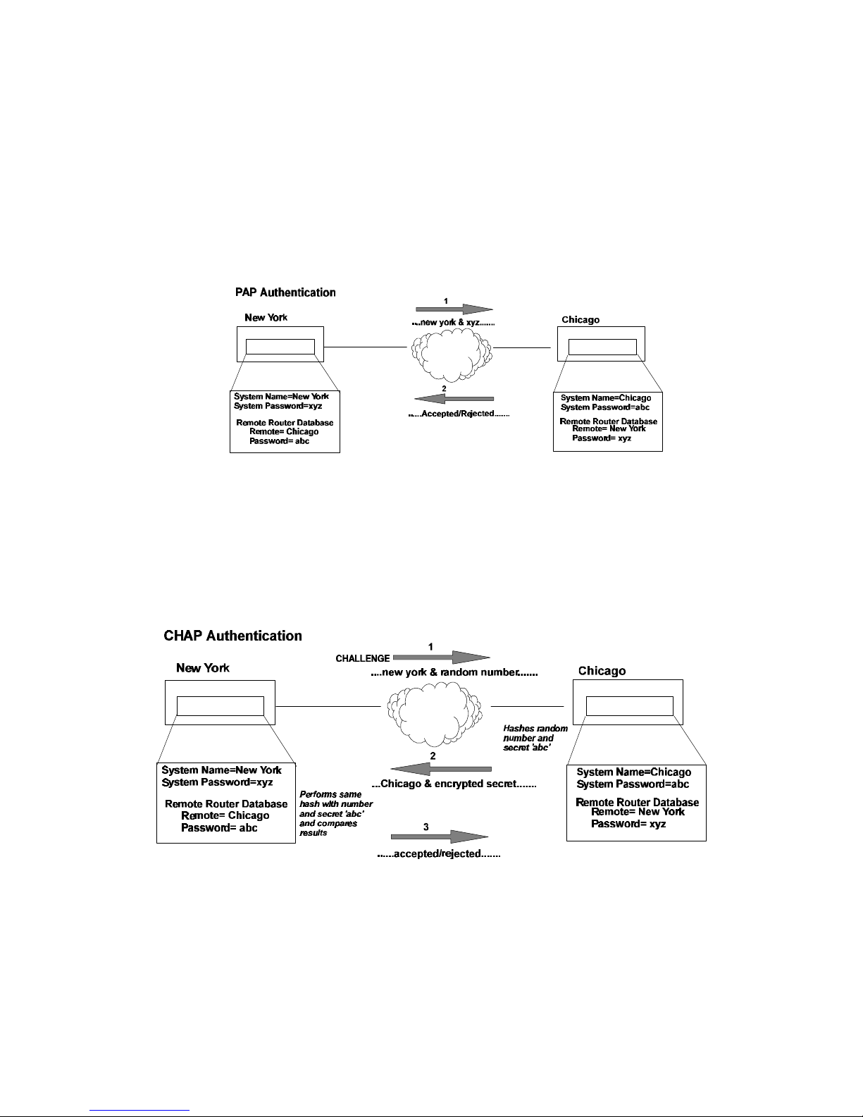
PAP provides verification of passwords between routers using a 2-way handshake. One router (peer)
sends the system name and password to the other router. Then the other router (known as the
authenticator) checks the peer’s password against the configured remote router’s password and returns
acknowledgment.
CHAP is more secure than PAP as unencrypted passwords are not sent across the network. CHAP
uses a 3-way handshake. One router (known as the authenticator) challenges the other router (known
as the peer) by generating a random number and sending it along with the system name. The peer
then applies a one-way hash algorithm to the random number and returns this encrypted information
along with the system name. The authenticator then runs the same algorithm and compares the result
with the expected value. This authentication method depends upon a password or secret known only
to both ends.
Security Configuration Settings
The FlowPoint Router has one default system password used to access any remote router. This ‘system
authentication password’ is utilized by remote sites to authenticate the local site. The router also
allows you to assign a unique ‘system override password’ used only when dialing out to a specific
remote router for authentication by that remote site. Each remote router entered in the remote router
Advanced Topics
7
Page 18
database has a password used when the remote site attempts to gain access to the local router. This
‘remote authentication password’ is utilized by the router to authenticate the remote site.
Each remote router entered in the remote router database also has a minimum security level, known as
the ‘remote authentication protocol’, that must be negotiated before the remote router gains access to
the local router. In addition, a system-wide control, ‘system authentication protocol’, is available for
overriding the minimum security level in the entire remote router database.
Authentication Process
The authentication process occurs regardless of whether a remote router has dialed in or the local
router is dialing out, and even if the remote end does not request authentication. It is a bi-directional
process, where each end can authenticate the other using the protocol of its choice (provided the other
end supports it).
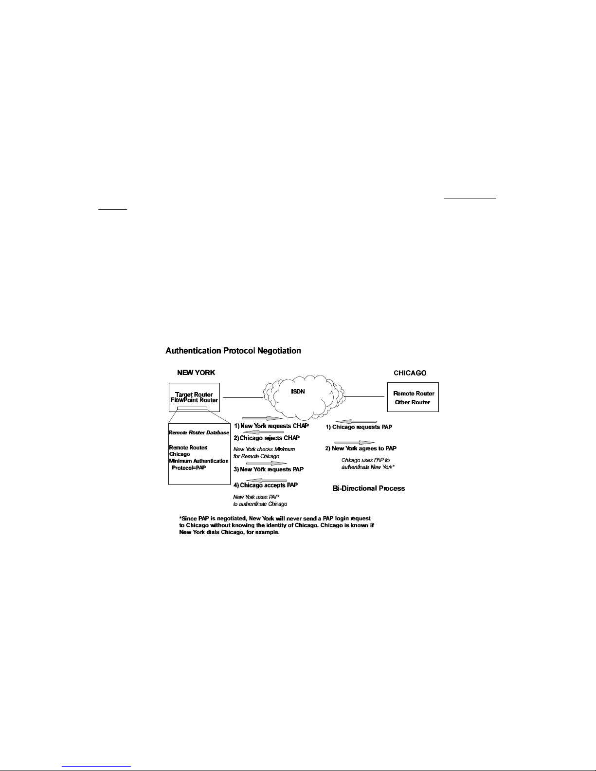
During link negotiation (LCP), each side of the link negotiates what protocol is to be used for
authentication during the connection. If both the system and the remote router have PAP
authentication, then PAP authentication is negotiated. Otherwise, the FlowPoint Router always
requests CHAP authentication first; if refused, PAP will be negotiated. If the remote end does not
accept either PAP or CHAP, the link is dropped; i.e., the FlowPoint Router does not communicate
without a minimum security level. On the other hand, the router will accept any authentication
scheme required by the remote node, including no authentication at all.
The following diagram illustrates the bi-directional negotiation that occurs between router New York
and router Chicago.
During the authentication phase, each side of the link can request authentication using the method
they negotiated during LCP.
For CHAP, the router issues a CHAP challenge request to the remote side. The challenge includes the
system name and random number. The remote end, using a hash algorithm associated with CHAP,
transforms the name and number into a response value. When the remote end returns the challenge
response, the router can validate the response challenge value using the entry in the remote router
database. If the response is invalid, the call is disconnected. If the other end negotiated CHAP, the
remote end can, similarly, request authentication from the router. The router uses its system name and
secret to respond to CHAP challenge.
8 FlowPoint’s User’s Guide: Command Line Interface
Page 19

For PAP, when a PAP login request is received from the remote end, the router checks the remote
router PAP security using the remote router database. If the remote router is not in the remote router
database or the remote router password is invalid, the call is disconnected. If the router and password
are valid, the router acknowledges the PAP login request.
If PAP was negotiated by the remote end for the remote-side authentication, the router will issue PAP
login requests only if it knows the identity of the remote end. The identity is known if the call was
initiated from the router or the remote end returned a successful CHAP challenge response. For
security reasons, the router will never identify itself using PAP without first knowing the identity of
the remote router.
If PAP was negotiated by the remote end for the local side of the authentication process and the
minimum security level is CHAP, as configured in the remote router database, the link is dropped for a
security violation.
Advanced Topics
9
Page 20

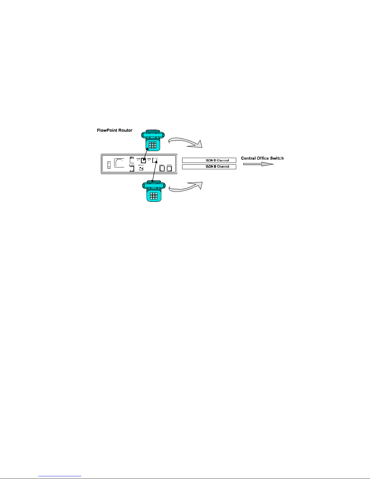
Bandwidth-On-Demand
Bandwidth-on-Demand enables bandwidth management of up to two ISDN
B-channels as the traffic load increases or decreases. This feature optimizes the use of dial-up WAN
resources ensuring that a channel is used only when needed and released as soon as it is no longer
required.
The Multi-Link Protocol for PPP (MLP) is used to implement this feature. MLP allows two Bchannels to be bundled together to provide 128KB of data transmission capacity.
Bandwidth-on-Demand Configuration Settings
This feature is controlled by five configuration settings: Maximum and Minimum Links, Bandwidth
Threshold, Fallback Interval2 and Bandwidth Management Direction. These settings are defined for
each remote site.
When traffic is sent or received, one or two channels can be used for the data transmission. The
configuration setting, maximum links, determines whether a maximum of one or two B-channels are
available for remote transmission. Minimum links determines whether one B-channel is permanently
allocated for the remote site connection or a channel is only allocated when needed.
Initially a call is activated on one B-channel. When bandwidth utilization reaches the bandwidth
threshold, the second B-channel is activated (if maximum links has been set to 2). Both channels are
utilized until the bandwidth utilization drops below the threshold after a fallback interval. The
fallback interval, in seconds, ensures that channels are not disconnected if traffic drops off for a small
interval while overall traffic continues to be heavy.
When two channels are utilized and traffic decreases to the point that one channel can be released, the
first channel acquired is released. Releasing this channel rather than the more recently acquired
channel may result in some cost savings since the first interval of ISDN access time tends to be the
most costly.
The technique used to calculate bandwidth utilization is a sliding window or moving average. Traffic
volume is sampled once per second and a moving average is computed by assigning a weight of 20%
to the last sample and a weight of 80% to the last average. After five seconds, no dependency is left
on previous traffic. Using a moving average technique, the bandwidth utilization average does not
drop off or spike upwards steeply if traffic decreases or increases during a few second interval (bursty
traffic, for example). This ensures an efficient management of link resources.
Bandwidth management can be applied to incoming, outgoing or both directions of traffic between the
router and the remote site.
2 This configuration setting is fixed at five seconds.
10 FlowPoint’s User’s Guide: Command Line Interface
Page 21

Protocol Conformance
Point-to-Point Protocol Standards
The implementation of PPP in the FlowPoint Router conforms to RFCs designed to address
performance, authentication, and multi-protocol encapsulation. The following RFCs are supported:
RFC 1661 PPP
Compression Control Protocol (CCP) Not yet an RFC, March 1994
draft being implemented
RFC 1990 Multi-Link Protocol (MLP)
RFC 1974 Stac LZS compression protocol
RFC 1962 PPP Compression Control Protocol (CCP)
RFC 1332 IP Control Protocol (IPCP)
RFC 1552 Novell IPX Control Protocol (IPXCP)
RFC 1220 Bridging Control Protocol (BNCP)
RFC 1334 Password & Challenge Authentication Protocols (PAP,
CHAP)
RFC 1144 Compressing TCP/IP headers (Van Jacobson)
RFC 1058 Routing Information Protocol
RFC 1723 RIP Version 2
For compression the STAC® Electronics Stacker LZS™ Compression Protocol is used in a manner
consistent with the February 1996 usage document.
IP Routing
IP routing support, conformant with RFC 791, provides the ability to process TCP/IP frames at the
network layer for routing. IP routing support includes the Routing Interface Protocol (RIP),
conformant with RFC 1058 (RIPv.1).
IPX Routing
IPX routing conforms to the Novell® NetWare™ IPX Router Development Guide, Version 1.10.
Advanced Topics
11
Page 22

System Files
The router’s file system is a DOS-compatible file system. The following list describes the contents of
the file system:
• SYSTEM.CNF Configuration files containing:
DOD Remote Router Database
SYS System Settings: name, message, authentication
method and passwords
ETH Ethernet LAN Configuration settings
POTS POTS Configuration data
• ISDN.DAT ISDN Settings files containing:
SPIDs
DNs
switch type
• DHCP.DAT DHCP files
• FILTER.DATBridge filters
• KERNEL.FP1 Router system software. (FP1 for the FlowPoint 100, FP5
for the FlowPoint 200)
• ETH.DEF These two files are used by manufacturing to set default Ethernet address or
ISDN.DEF switch types.
• UK.FAC For POTS routers: used to confiured different ring codes
Any file contained within the system may be retrieved or replaced using the TFTP protocol.
Specifically, configuration files and the operating system upgrades can be updated. Only one copy for
the router software is allowed in the router’s FLASH memory. Refer to Chapter 5. Managing the
Router or the Getting Started Guide for details on software upgrades, booting router software, copying
configuration files and restoring router software to FLASH.
12 FlowPoint’s User’s Guide: Command Line Interface
Page 23

Advanced Topics
13
Page 24

Page 25
Chapter 2. Planning for Router Configuration
Chapter 3 of the FlowPoint Getting Started Guide describes the configuration process and
terminology, and the information that you need to collect before configuring the router. This chapter
assumes that you have read the planning chapter in the Getting Started Guide, collected the network
information and drawn diagrams of your network. If you are configuring the router using the
Command Line Interface, planning is similar to the process described for the Configuration Manager
with very few exceptions.
The Command Line Interface has some additional features you may wish to use. Also, planning tables
(and worksheets) are included here but they refer to the commands used to configure the features
rather than the Configuration Manager menu selections.
Advanced Command Line Interface Features
Bridging Filtering
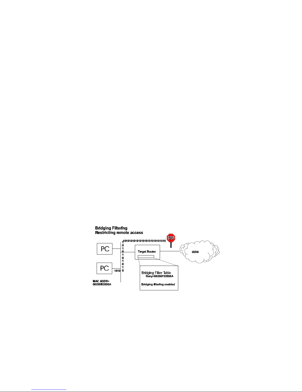
You can control the flow of packets across the router using bridging filtering. Bridging filtering lets
you ‘deny’ or ‘allow’ packets to cross the network based on position and hexadecimal content within
the packet. This enables you to restrict or forward messages with a specified address, protocol or data
content. Common uses are to prevent access to remote networks, control unauthorized access to the
local network and limit unnecessary traffic.
For example, it might be necessary to restrict remote access for specific users on the local network. In
this case, bridging filters are defined using the local MAC address for each user to be restricted. Each
bridging filter is specified as a ‘deny’ filter based on the MAC address and position of the address
within the packet. Deny filtering mode is then enabled to initiate bridge filtering. Every packet with
one of the MAC addresses would not be bridged across the router until the deny filtering mode was
disabled.
Similarly, protocol filtering can be used to prevent a specific protocol from being bridged. In this case,
the protocol id field in a packet is used to deny or allow a packet. You can also restrict, for example,
the bridging of specific broadcast packets.
ISDN Subaddressing
ISDN subaddressing enables ISDN devices connected on an S/T interface to be addressed uniquely by
an address or identifier. Subaddressing information is passed between ISDN peers during call set-up
of ISDN connections and is used to target communications to a specific ISDN device (similar to a
Planning for Router Configuration
15
Page 26
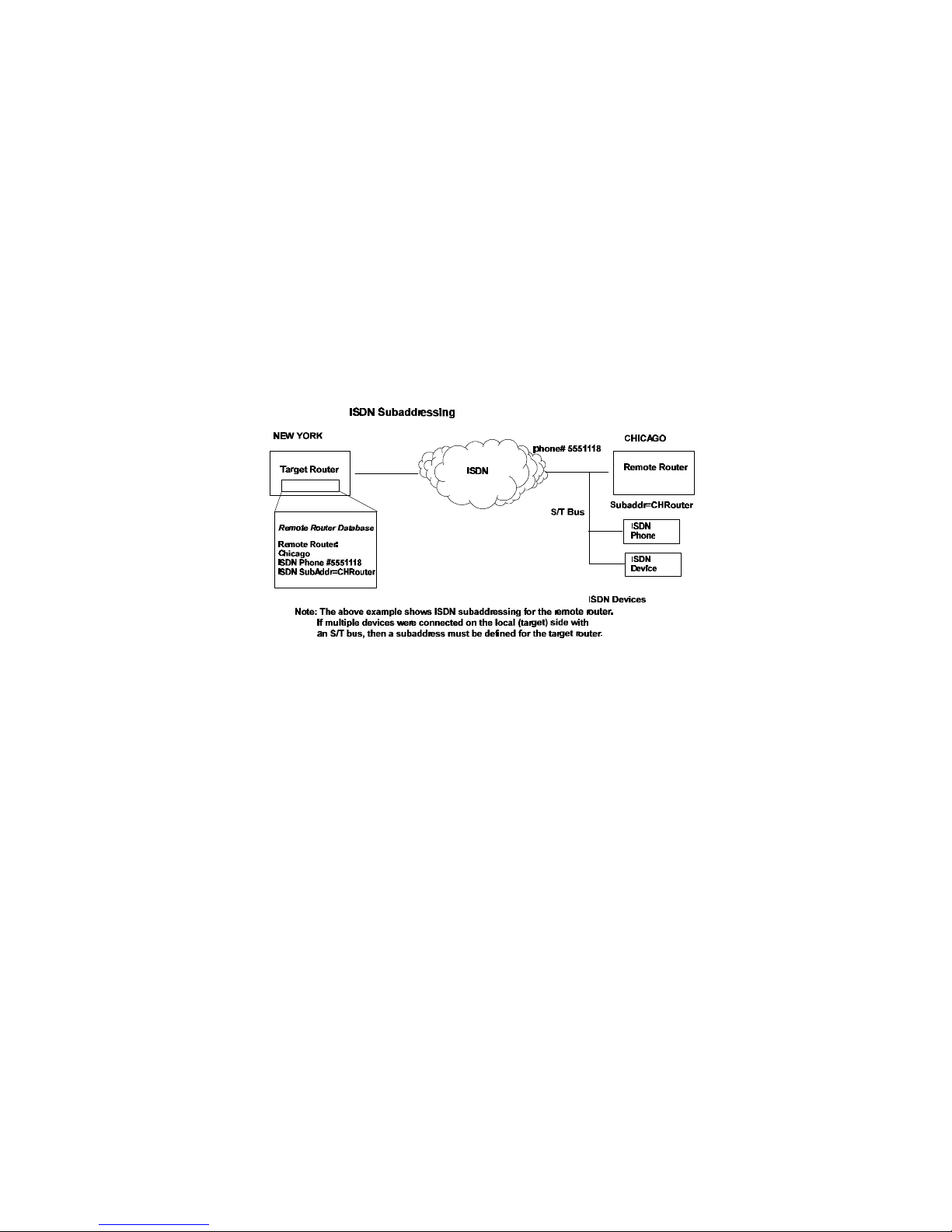
multi-point leased line capability). Subaddressing allows you to have one telephone number for the
ISDN equipment and provides an alternative to having a unique telephone number for each ISDN
device. Subaddressing can be used whether one or more devices are connected to an S/T interface.
ISDN Subaddressing Configuration Settings
ISDN subaddressing configuration involves setting a subaddress for the local router and/or
subaddresses for the remote routers. The subaddresses can be user-defined or network service access
points (NSAPs), a format defined by the international standard Q.931.
Each device on an S/T interface ‘sees’ the subaddress with the incoming transmission, but only the
addressed device processes the packet. If a subaddress has been defined for the FlowPoint Router, only
transmissions that have a correct subaddress will be accepted, and a subaddress must be sent. If
subaddressing is not defined and a transmission is received with a subaddress, the call is ignored.
Note that the FlowPoint Router will never clear a call if subaddressing is incorrect; the call will be
ignored.
Unique System Passwords
As described in the section Security Configuration Settings in Chapter 1. Advanced Topics, you can
specify a unique system override password for a remote router. This ‘system override password’ is
used instead of the general system password only when dialing out to a specific remote router. This
allows you to set a unique CHAP or PAP authentication password for authentication of the local site by
the remote site only when the router dials out to that remote site. A common use would be to set a
password assigned to you by Internet Service Providers. Similarly, the system name of the local router
can be overridden when dialing out to a specific remote (system setoursysname).
Analog Services
The router’s analog services allow for attaching analog telephones, fax machines and/or modem
equipment to the POTS interfaces. This support lets you specify how phone numbers are associated
with the POTS interfaces, whether the POTS interfaces can be used for dialing as well as for
answering and whether voice calls have priority over data calls.
POTS Interfaces and Telephone Numbers
Your ISDN service provider has given you one or more telephone numbers that other locations or
persons can dial to access the router. When you have attached analog devices, you need to associate
these telephone numbers with the POTS interfaces so that an incoming voice call can be assigned to
the correct analog port.
16 FlowPoint’s User’s Guide: Command Line Interface
Page 27
If you have a North American central office switch and have configured two SPIDS/DNs, the default
configuration is DN1 is associated with POTS interface 1 and DN2 is associated with POTS interface
Otherwise, the default configuration is an incoming call will ring on all available devices attached to
the POTS interfaces. An outgoing call will use any available B-channel.
You may wish to assign telephone numbers to distinct analog devices. You can configure these
numbers into the target router’s system settings and then associate a unique telephone number with
each POTS interface. You also have the option of assigning a telephone number to both POTS
interfaces.
Directory Phone Number 555-1111
Directory Phone Number 555-1112
Analog Service Mode
You can designate a POTS interface to answer incoming calls and /or for dialing out. The default
configuration sets both answer and dial mode for the two POTS interfaces.
Call Preemption
Call preemption allows you to give voice calls priority over data calls. Call preemption means a
voice call (depending on the configuration options) will cause a disconnect of a data call on an ISDN
B-channel. The default configuration is for both incoming and outgoing voice calls to preempt data.
You can specify that incoming and/or outgoing voice calls preempt data calls or that no preemption
occurs unless two data channels are in use to the same destination. A ‘no preemption’ configuration
ensures that a data connection is maintained on at least one channel.
In all cases, a voice call will preempt one data channel if two channels are in use to the same
destination. If preemption is designated for outbound calls and an outbound voice call is initiated
while two data channels are in use to different destinations, the router will randomly select a Bchannel to disconnect the data call. If preemption is designated for inbound calls and an inbound
voice call comes in while two data channels are in use to different destinations, the router will also
randomly select the line to preempt.
Call preemption does not occur on incoming calls unless a person picks up the phone or the analog
equipment answers the call.
An incoming voice call may not always be forwarded from the central office if two B-channels are
already in use for data calls. You must subscribe to a service called ‘Additional Call Offering’ for the
voice call to be forwarded to the router.
CallerID Security
CallerID is an additional security feature on data calls supported by the router. CallerID allows you to
verify phone numbers of the remote routers when calls come in to the local router. This feature is
Planning for Router Configuration
17
Page 28

system-wide and you must configure the phone numbers from which a remote router can call. Any
calls from other numbers will be rejected. The allowable phone numbers must be obtained from the
remote locations or your network administrator.
Call Management
The router supports call management features that allow you to control ISDN line usage charges on
data calls.
Dial-Back
Dial-Back lets you force the router to reject an incoming call from another router and dial that router
back. You can use this feature to cause ISDN phone charge billing to the local router. Dial-Back can
be enabled, disabled or enabled such that Dial-Backs occur only if called by the remote router first.
When Dial-Back is configured, the local router’s call delay timer setting must allow for disconnect and
dial back; the defaults (30 seconds for the U.S. and 90 seconds for Europe, Japan) or longer should be
acceptable and Caller ID must be enabled.
PPP CallBack
PPP CallBack is a negotiated feature between routers. The local router requests that the remote router
disconnect and call the local router back. If accepted, this feature results in ISDN phone charge
billing to the remote router. You must obtain from your network administrator or the remote location,
details on what the remote end needs for this feature. The router can send a phone number, a phone
number in E164 format, or a name. When CallBack is configured, the remote router’s call delay timer
setting must allow for disconnect and call back.
With PPP CallBack, two phone calls are actually placed; Dial-Back may be cheaper to use.
Data as Voice
The “Data as Voice” feature causes data calls to be sent as voice calls over the ISDN service in the
U.S. and may result in reduced line charges. You can configure a system-wide feature that allows you
to receive data calls as voice calls and you will not be able to use the POTS interface for incoming
voice calls. You can also cause data calls to be sent as voice calls to a specific remote router.
Warning: This feature must be used with care. Both ends of the connection must agree to configure
calls in this manner and the feature may not work depending on the central office service.
18 FlowPoint’s User’s Guide: Command Line Interface
Page 29

Network Information Tables
The following tables list the items you need to define or obtain to configure the router. This
information was described and illustrated on network information diagrams in the Getting Started
Guide. The unique Command Line Interface features are highlighted in bold text. Worksheets are
provided in Appendix A so that you can enter details about your target router and remote routers. The
worksheets show the commands associated with setting the features.
IMPORTANT NOTE: To configure the target router, you need to fill out one Target Router chart
for the target router and one Remote Router chart for each remote router to be entered into the remote
router database. If you are setting up both ends of the network, you will need a mirror image of the
information listed below for configuring the router on the other end of the ISDN link.
TARGET ROUTER (SOHO)
Target
Router
Settings
System
Settings
Item Description
Router Name
Name used to identify this router; sent to other routers during
PAP/CHAP security authentication
ISDN Settings
Analog
Interface
Settings
Message
Authentication
Protocol
Dial Authentication
Password/Secret
CallerID
Data as Voice
ISDN Line Numbers
(supplied by the
service provider, if
applicable)
Type of telco switch
Subaddress (if used)
POTS Phone Numbers
Answer/Dial Mode
Message saved in the router to be read by a system administrator
(optional)
Force PAP or CHAP authentication protocol
This router’s password used for authentication when the router
dials out to other routers or is challenged
Caller ID on or off
Receive Data as Voice Calls
SPIDs and Directory Numbers for one or two ISDN B-Channels
on this router
NTT Nippon Telegraph/Telephone
KDD Kokusai Denshin Denwa Co. AT&T 5ESS w/Custom
Software Northern Telecom DMS-100
NI1 National ISDN 1
NET3 European ISDN
NET3SW Swiss-variant ISDN
HDS64 64Kb permanent connection
HDS128 128Kb permanent connection
ISDN Subaddress for the router
Assign ISDN Phone Numbers for POTS interfaces
Answer, Dial or Both
Call Preemption
Control
Planning for Router Configuration
IN/OUT/BOTH/NONE for POTS interfaces
On or Off
19
Page 30

Ethernet IP
Settings
Ethernet IP Address
and Subnet Mask
LAN gateway address
Address and Subnet Mask for Ethernet Port Connection
Ethernet LAN IP
TCP/IP routing to all destinations On or Off
Routing On/Off
Ethernet LAN IP
Internet Firewall On or Off
Internet Firewall
Ethernet IPX
Settings
Ethernet LAN IP
Options
Ethernet IPX Address
and frame type
Ethernet LAN IPX
Transmit/Receive RIP packets/routes and advertise as default
route
Network Number for Ethernet LAN connection
IPX routing to all destinations On or Off
Routing ON/OFF
Bridging
Bridging Filters Bridging Filters to deny or allow
Filters
REMOTE ROUTER (HQ) - IN REMOTE ROUTER DATABASE
Remote Router
Item Description
Settings
Dial Up Settings
Bandwidth
ISDN Phone Numbers,
SubAddress
Disconnect Timer
Maximum Links
ISDN Phone Numbers for one or two B-Channel(s), ISDN
Subaddress
Disconnect Line on Inactivity
Maximum links (up to 2 ISDN lines)
Management
Minimum Links
Minimum links (up to max links)
Security
Call
Management
Threshold
Bandwidth Direction
Minimum
Authentication Protocol
Password/Secret
Unique system override
password
CallerID phone numbers
Dial-Back
PPP CallBack
Data as Voice
% threshold to access second channel
Management on IN|OUT|BOTH
PAP|CHAP|NONE minimum protocol required for remote
router
Remote router’s password used for authentication of target
router
Password used by remote router for authentication of target
router
Phone numbers to validate on incoming calls
Disconnect and dial the remote router back ON|OFF|ONLY
Request call back when calling remote router
Send data as a voice call
20 FlowPoint’s User’s Guide: Command Line Interface
Page 31

TCP/IP Routing
IP Address, Subnet
Mask, and Metric
IP Address, Subnet Mask of remote network/station beyond the
remote router and route efficiency metric
Remote Router WAN IP
Addr/Subnet Mask *
Target WAN IP Address
and Subnet Mask *
IP RIP options
NetWare IPX
Routing
IPX Routes: Network
Number, Hop Count and
Ticks
IPX SAPs: Server Name,
Network Number, Node
Number, Socket Number
Server Type, Hop Count
WAN Network Number
Bridging
Default Destination
Remote MAC
address(es)
Bridging On/Off
Spanning Tree Protocol
* Used only in PPP numbered mode of addressing
IP Address and Subnet Mask of the Remote Router
IP Address and Subnet Mask of the local end of the WAN link
Transmit/receive RIP, default routes
IPX Network Number, Hop Count and Ticks for stations/nodes
beyond the remote router. Hop count is number of routers to
pass through and ticks is time delay (in 1/18 sec)
Information defining application services available on
stations/nodes beyond the remote router
Network Number for the WAN link between target and remote
router
Default outbound destination
Remote bridging addresses to seed bridging table
Enable/Disable bridging
Use Spanning Tree Protocol
Planning for Router Configuration
21
Page 32

Sample Configuration
A sample configuration of a hypothetical network is provided in this section. The following diagram
depicts a small office (SOHO) accessing a central site (HQ) via an ISDN link. The small office also
has access to the Internet through an Internet Service Provider (ISP), using a password specifically for
the ISP. An analog telephone and a fax machine are attached to the router and voice calls have
priority over data calls. Two distinct numbers are associated with the POTS interfaces.
The small office and central site have IP routing with a Class B addressing scheme, and IPX routing.
Bandwidth-on-demand is configured for accessing central site HQ. A maximum of one line is
configured for calling the ISP (though two different phone numbers are defined for use). Network
information worksheets and the actual commands show configuration of router SOHO at the small
office.
SAMPLE NETWORK DIAGRAM
Small Office SOHO (Target Router)
Internet Service Provider ISP Central Site HQ
22 FlowPoint’s User’s Guide: Command Line Interface
Page 33

TARGET ROUTER: SOHO
Command Item Setting
system name Router Name
system msg Message
system authen Dial Authentication Protocol
forced
system passwd Dial Authentication
Password/Secret
system callerid CallerID On/Off
system dataasvoice Receive Data as Voice
isdn set spids ISDN SPID#1
ISDN SPID#2
isdn set dn ISDN Directory Number #1
ISDN Directory Number #2
isdn set switch ISDN Switch Type
isdn set subaddr ISDN Subaddress
pots add ISDN POTS1
ISDN POTS2
pots set line Answer/Dial Mode
pots set preempt Call Preemption On/Off
pots ena/disable Analog Service On/Off
eth ip addr Ethernet IP Address and Subnet
Mask
eth ip ena/dis TCP/IP Routing On/Off
eth ip options Ethernet LAN IP Options
eth ip firewall Ethernet IP Internet Firewall
On/Off
eth ipx addr Ethernet IPX Address
eth ipx ena/dis NetWare IPX Routing On/Off
filter br Bridging Filtering offsets and
hex numbers
SOHO
Configured_Mar_1996
Default (None)
SOHOpasswd
Default (Off)
Default (Off)
ISDN SPID1 0555100001
ISDN SPID2 0555300001
DN1 5551000
DN2 5553000
DMS-100
Not Used
Defaults
Default (Both)
Default (Both)
Default (On)
128.1.129.1 255.255.255.0
IP Routing On
Defaults
Internet Firewall On
456
IPX Routing On
None
Planning for Router Configuration
23
Page 34

REMOTE ROUTER: HQ (Central Site)
Command Item Setting
setPhone
ISDN Phone #1 ISDN
Phone #2
5552000
5554000
setSubAddr
setTimer
setMax(Min)Line
setBWThresh
setBod
setAuthen
setPasswd
setOurSysName
setOurPasswd
addCallerID
setDialBack
setPPPCallBack
setDataAsVoice
addIpRoute Remote Network’s IP Addresses,
setIpOptions IP RIP protocol options
setSrcIpAddr
setRmtIpAddr
addIpxRoute IPX Routes: Network Number,
addIpxSap IPX SAPs: Server Name,
setIpxAddr Remote WAN IPX addr
addBridge Default Bridging Destination (*)
ena/disBridge Bridging On/Off
setBrOptions Spanning Tree Protocol
ISDN Subaddress
Disconnect Timer
Min/Max Links
Bandwidth Threshold
Bandwidth Direction
PAP | CHAP | NONE
Remote Router’s Password/Secret
System Name Override
System Password Override
CallerID Phone Numbers
Dial-Back On/Off/Only
PPP CallBack On/Off
Send Data as Voice
Subnet Masks, and Metrics
Remote WAN IP Address and
Subnet Mask**
Source WAN IP Address and
Subnet Mask**
Hop Count, Ticks
Network#, Node#, Socket#
Server Type and Hop Count
or Remote MAC address(es)
** PPP addressing Numbered Mode only
None
Default (60 seconds)
Defaults 0/2
75%
Input and Output
CHAP
HQpasswd
Default (None)
Default (None)
None
Default (Off)
Default (Off)
Default (Off)
128.1.0.0 255.255.0.0 1
Defaults
Not required
Not required
1001 2 4
SERV312_FP 1001 00:00:00:00:00:01 451 4 2
789
HQ Default Bridging Destination (*)
Bridging ON
Default (Off)
REMOTE ROUTER: ISP (Internet Service Provider)
Command Item Setting
24 FlowPoint’s User’s Guide: Command Line Interface
Page 35

setPhone
ISDN Phone #1
ISDN Phone #2
5551115
5551116
setSubAddr
setTimer
setMax(Min)Line
setBWThresh
setBod
setAuthen
setPasswd
setOurSysName
setOurPasswd
addCallerID
setDialBack
setPPPCallBack
setDataAsVoice
addIpRoute Remote Network’s IP Addresses,
setIpOptions IP RIP protocol options
setSrcIpAddr
setRmtIpAddr
addIpxRoute IPX Routes: Network Numbers,
addIpxSap IPX SAPs: Server Name,
setIpxAddr Remote WAN IPX addr
addBridge Default Bridging Destination or
ena/disBridge Bridging On/Off
setBrOptions Spanning Tree Protocol
ISDN Subaddress
Disconnect Timer
Max/Min Links
Bandwidth Threshold
Bandwidth Direction
PAP | CHAP | NONE
Remote Router’s Password/Secret
System Name Override
System Password Override
CallerID Phone Numbers
Dial-Back On/Off/Only
PPP CallBack On/Off
Send Data as Voice
Subnet Masks, and Metrics
Remote WAN IP Address and
Subnet Mask**
Source WAN IP Address and
Subnet Mask**
Hop Count, Ticks
Network#, Node#, Socket# Server
Type and Hop Count
Remote MAC address(es)
** PPP addressing Numbered Mode only
None
Default (60 seconds)
Default (1/0)
Default (0%)
Input and Output
PAP
ISPpasswd
(username)
f1xypst
None
Default (Off)
Default (Off)
Default (Off)
0.0.0.0 255.255.255.255 1
Defaults
Not required
Not required
Not required
Not required
Not required
Not required
Bridging OFF
No
Planning for Router Configuration
25
Page 36

Configuration Commands for SOHO Target Router
login admin
system admin newpass
system name SOHO
system msg configured_mar_1996
system passwd SOHOpasswd
system list
save sys
isdn set switch dms100
isdn set spids 0555100001 0555300001
isdn set dn 5551000 5553000
isdn list
save isdn
pots list
eth ip addr 128.1.129.1 255.255.255.0
eth ip ena
eth ipx addr 456
eth ipx ena
eth list
save eth
remote add HQ
remote setPhone isdn 1 5552000 HQ
remote setPhone isdn 2 5554000 HQ
remote setMaxLine 2 HQ
remote setBWThresh 75 HQ
remote setAuthen chap HQ
remote setPasswd HQpasswd HQ
remote addIpRoute 128.1.1.0 255.255.0.0 1 HQ
remote addIpxRoute 1001 2 4 HQ
remote addIpxSap SERV312_FP 1001 00:00:00:00:00:01 451 4 1 HQ
remote setIpxAddr 789 HQ
remote addBridge * HQ
remote enaBridge HQ
remote list HQ
remote add ISP
remote setPhone isdn 1 5551115 ISP
remote setPhone isdn 2 5551116 ISP
remote setTimer 60 ISP
remote setPasswd ISPpasswd ISP
remote setOurPasswd f1xypst ISP
remote addIpRoute 0.0.0.0 255.255.255.255 1 ISP
remote list isp
save
reboot
ifs
isdn list
iproutes
ipxroutes
remote list
26 FlowPoint’s User’s Guide: Command Line Interface
Page 37

Chapter 3. Configuring FlowPoint Router Software
The Command Line Interface is available to you at all times after you have installed the router
hardware, connected a PC with a terminal emulation session (or ASCII terminal), and powered the
unit on. This section assumes that you have successfully followed the instructions in Chapter 1.
Installing FlowPoint Router Hardware in the Getting Started Guide. If you intend to use the
Command Line Interface through the Configuration Manager, it is assumed that you have installed the
Configuration Manager software and can access the terminal window.
Configuration Overview
You can configure all of the basic features (steps 1 through 16), save the entire router configuration
directly into FLASH memory, reboot the router and then verify the configuration.
You can then configure the optional special features, save those settings, reboot and then test each
function.
Using the Command Line Interface, you will execute the following steps:
Basic Configuration
1. Log into the router
2. Configure the router’s system name, optional message and
dial authentication password
3. Specify the router’s ISDN line settings
4. Configure the router’s Ethernet LAN IP/IPX addresses
5. Add remote router(s) to the Remote Router Database
6. Configure dial-up link information
7. Configure bandwidth management
8. Set up security
9. Set up IP routing
10. Set up IPX routing
11. Set up bridging
12. Configure analog settings
13. Save the configuration
14. Reboot the router
15. Verify the router’s configuration
16. Logout
Configuring FlowPoint Router Software
27
Page 38

Optional Special Features
• Configure the Ethernet Firewall and/or bridging filtering
• Configure CallerID security
• Configure call management
NOTE 1: Each setting you specify results in a dynamic update of the router’s configuration, but some
changes will not alter the active configuration until you save and reboot the router.
If you change any of the following settings, you must reboot the router for the changes to take
effect:
• Ethernet LAN: Ethernet IP or IPX Address, TCP/IP Routing, IPX Routing
• Bridging: Bridging default destination, Filters
• Remote Router: TCP/IP Route Addresses, IPX Routes, IPX SAPs and Bridging control, enable,
disable or add remote routers
Refer to Chapter 4. Command Line Interface Reference for usage conventions and a complete
description of the commands mentioned in this chapter.
28 FlowPoint’s User’s Guide: Command Line Interface
Page 39

Basic Configuration
Step 1. Log into the Target Router
Log in with the following command:
login password
where password is an administration password. The default password is admin. The password can
be reset using the system admin command.
The login password is required if you intend to modify the router’s configuration settings. This
security feature prohibits unauthorized write access to the router’s configuration. If you do not log in
with the write enable login password, you are prevented from issuing any command that changes the
router’s configuration and from rebooting the router. You will receive the message ‘command not
authorized’.
Step 2. Set Target System Settings
Now enter information about the target router you are configuring and adding to your network. This
information includes the system administration password, system name, optional message and dial
authentication password.
Set the System Administration Password
If you want to change the login password from the default admin, enter the following command:
system admin password
where password is the new administration password.
Set the System Name
The system name is required. This name is sent to other routers during authentication. Set the name
of the target router using the command:
system name name
where name is a case-sensitive character string used to identify the router. Space characters are not
allowed within the name; you may use underscore characters instead. (The system name is a ‘word’
when exchanged with PAP/CHAP. If you type anything after system name, the characters will be
taken as the new name. If you wish to present a different name to each remote router, use the
command:
remote setOurSysName name remoteName
Configuring FlowPoint Router Software
29
Page 40

Set a System Message
You may enter an optional message which is saved in the router. The message is useful for specifying,
for example, the name of the person configuring this router and the last changes made. Enter the
command:
system msg msg
where msg is a character string. Space characters are not allowed within the message; you may use
underscore characters instead. If you do not enter a message following system msg, the current
message is displayed (underscores are converted to spaces.)
Set the Dial Authentication Password
The target router’s dial authentication password is used for authentication when the target router dials
out to other routers or is challenged by them. To set the password, enter:
system passwd password
where password is a case-sensitive character string. A new password overrides the previous one set.
Existing passwords cannot be displayed. If you wish to set a unique password used only when the
router dials to a specific remote router, you must also use the command:
remote setOurSysName name remoteName
To list the system settings, enter the command system list
The following is typical output from this command:
GENERAL INFORMATION FOR <HQ>
System started on.................... 11/15/1996 at 11:26
Authentication override.............. NONE
IP address translation............... none
Caller ID Security selected.......... none
Receive Data Call as Voice........... no
BOOTP/DHCP Relay address............. 192.84.210.101
System message: Configured October 1996
If you are satisfied with the system settings, save them to FLASH memory, with the command:
save sys
Step 3. Set Target System ISDN Settings
CAUTION: For U.S. routers only
You MUST configure the ISDN System Settings parameters FIRST, before plugging in the ISDN
line. Failure to do so will cause the Central Office switch to behave erratically for some time.
Set ISDN Switch Type
If the router supports ISDN, you must enter ISDN line information. Specify the telephone switch type
your ISDN service provider is using with the following command:
isdn set switch switchType
30 FlowPoint’s User’s Guide: Command Line Interface
Page 41

where switchType is one of the following:
NTT Nippon Telegraph and Telephone (NTT)
KDD Kokusai Denshin Denwa., Ltd.
5ESS AT&T 5ESS w/Custom Software
DMS100 Northern Telecom DMS-100
NI1 National ISDN-1-compliant switches
NET3 European ISDN/ETSI
NET3SW Swiss NET3 variant
HSD64 64Kb permanent connection
HSD128 128Kb permanent connection
Set SPIDs and Directory Numbers
The service provider may assign to you none, one, or two SPIDs and/or DNs for identifying the ISDN
line and devices. This varies by service provider and country. Refer to Appendix D. ISDN BRI Line
Ordering and Configuration in the Getting Started Guide for more information.
SPIDS: Enter ISDN Service Provider IDs (SPIDS) with the following command:
isdn set spids spid#1 spid#2
where spid#1 is the first or only SPID number and spid#2 is the second SPID number. One
ISDN SPID may be assigned for each B-channel of the ISDN BRI line, one SPID may be assigned for
both channels, or SPID numbers may not be provided at all.
DNs: Enter directory numbers corresponding to the ISDN B-channels with the following command:
isdn set dn dn#1 dn#2
where dn#1 is the first or only directory number and dn#2 is the second directory number. One
ISDN directory number may be assigned for each B-channel of the ISDN BRI line, one directory
number may be assigned for both channels, or directory numbers may not be provided at all. The
SPID may be the Directory Number extended with additional digits.
Set Subaddressing
You can assign a subaddress to the router that lets remote routers uniquely identify this ISDN device
during call set-up. Use the command:
isdn set subaddr u|n <string>
where u refers to a user defined subaddress and n refers to the international standard NSAP address.
Refer to the command reference section for more details on the syntax.
Allow or exclude outgoing and/or incoming data calls
You can decide whether to allow or lock out data calls. This feature is particularly useful if your
router is configured to bridge and you want to ensure that no data calls are made or received by your
POTS lines. Use the command:
isdn set DataCallsAllowed <option> [YES|NO]
Refer to the command reference section for more details on the syntax.
Configuring FlowPoint Router Software
31
Page 42

Save, Reboot, and List ISDN settings
Save the ISDN settings to FLASH memory with the command:
save isdn
Do not power down immediately after the save command. First type the command sync to
synchronize the file system with the disk cache.
Then reboot the router with the command: reboot
The router will go through POST and reboot the router software. Note that whenever you reboot the
router, you must log in again if you wish to change the router’s configuration.
NOTE: If you do not save the configuration to FLASH, the configuration is lost upon reboot or
power down of the router.
Connect ISDN line and check ISDN status
Now that the reboot has been completed, it is safe to connect the ISDN line to the router.
To list all the current ISDN settings and check status, enter the command:
isdn list
You should receive results similar to the following:
# isdn list
DSL 0 is Idle
Switch type is Northern DMS-100
ISDN Outgoing data calls allowed: yes
ISDN Incoming data Calls allowed: yes
Retry failed calls every 30 seconds
CES: 1: 4083648318/3648318 TEI 77 assigned
CES: 2: 4083648319/3648319 TEI 78 assigned
ISDN/2 Idle ces=0 cid=-1 not assigned
ISDN/3 Idle ces=0 cid=-1 not assigned
Step 4. Set Target System Ethernet LAN Addressing
You will now initialize the router’s Ethernet LAN IP address or the Ethernet LAN IPX network
number if you use IPX routing. If you are configuring the router at the office headquarters and then
installing the router at a branch office, use the Ethernet LAN addressing of the LAN at the branch
office. If you intend to test the router at the host site first, enter the LAN address of the host site. If
you change the addresses, you must perform a Save and Reboot as shown in later steps.
Initialize Ethernet IP address
Enter the command:
eth ip addr x.x.x.x y.y.y.y
where x.x.x.x is the IP address and y.y.y.y is the subnet mask for the router’s Ethernet LAN
connection. No checking is performed on the addresses.
The command eth list lists the settings for the Ethernet LAN IP address and subnet mask as well
as the port number. The command also lists routing and bridging status. Following is a sample of the
results of this command:
32 FlowPoint’s User’s Guide: Command Line Interface
Page 43

# eth list
ETHERNET INFORMATION FOR <ETHERNET/0>
Hardware MAC address................. 00:20:6F:02:4B:41
Bridging enabled..................... no
IP Routing enabled................... no
LinkShare default IP Address......... 0.0.0.0
Firewall filter enabled ........... yes
Process IP RIP packets received.... yes
Send IP RIP to the LAN............. no
Advertise me as the default router. no
Receive default route using RIP.... yes
IP address/subnet mask........ 128.1.129.1/255.255.255.0
IP static default gateway............ none
IPX Routing enabled.................. no
External network number............ 00000123
Frame type......................... 802.3
Eth list is a useful command to verify that the router’s LAN IP address and subnet mask are set
correctly.
Note that firewall filtering, sending and receiving RIP packets, advertising the default route and
receiving the default route are set on.
NOTE 1: The preceding response shows you that, at present, bridging is disabled and routing from the
LAN is enabled. This is the initial status when you install the router
NOTE 2: If another router on the local LAN has been specified as the default router, you should
disable the router from advertising itself as the default router. To do this, enter:
eth ip options avdfr off
Enable Ethernet IP Routing
At this point you can enable IP routing, save the configuration, and reboot the router to test the
router’s local IP connectivity and the ISDN line configuration.
Otherwise, you can continue on to initialize the IPX LAN address for IPX routing as described on
page 34or add remote routers as described in Step 5 on page 34. To enable IP routing, enter the
following command:
eth ip ena
Save the information to FLASH memory:
save eth
Then reboot the router with reboot
Note: If you do not save the configuration to FLASH, the configuration is lost upon reboot or
power down of the router.
You can verify IP connectivity by running a PING (an IP echo facility) to the target router.
Also verify that the ISDN line is in standby status. Enter the isdn list command or use the
command ifs to list the status of all interfaces. You should receive a response similar to the
following:
# ifs
Interface Speed In% Out% Protocol State Connection
ETHERNET/0 10mb 0%/0% 0%/0% (Ethernet) OPENED
ISDN/3 0 b (HDLC/PPP) STANDBY
ISDN/2 0 b (HDLC/PPP) STANDBY
ISDN-D/0 16kb 0%/0% 0%/0% (HDLC/LAPD OPENED
Configuring FlowPoint Router Software
33
Page 44

CONSOLE/0 9600 b 0%/0% 0%/0% (TTY) OPENED
Initialize Ethernet IPX address
If you intend for the router to perform IPX routing, you need to set the Ethernet IPX address. Enter the
command:
eth ipx addr network#
where network# is the external Network Number for the LAN segment that the router is on. No
checking is performed on the network number.
You may also need to set the frame type, which is the encapsulation method used to send multiple
network-level protocols over the LAN or WAN link. The default frame type is 802.2. If you need to
change the frame type, enter the command:
eth ipx frame type
where type is the encapsulation method (802.2, 802.3, or dix).
Verify that you have entered your parameters correctly with the following command eth list.
This command lists the settings for the Ethernet LAN address as well as other Ethernet LAN
information including routing and bridging status. Following is a sample of the results of this
command:
# eth list
ETHERNET INFORMATION FOR <ETHERNET/0>
Hardware MAC address................. 00:20:6F:02:4E:A0
Bridging enabled..................... yes
IP Routing enabled................... yes
Firewall filter enabled ........... yes
Send IP RIP to the LAN............. rip-1 compatible
Advertise me as default router... no
Process IP RIP packets received.... rip-1 compatible
Receive default route by RIP..... yes
RIP Multicast address................ none
IP address/subnet mask............... 128.1.129.1/255.255.255.0
IP LinkShare default address......... none
IP static default gateway............ none
IPX Routing enabled.................. yes
External network number............ 00000456
Frame type......................... 802.2
Save the Ethernet LAN configuration to FLASH memory with save eth.
Verify that the ISDN line is in standby status. Enter the isdn list command or use the command ifs to
list the status of all interfaces.
Step 5. Add Remote Routers into Remote Router Database
You must now enter all the remote routers to which this router may connect into the remote router
database and specify details about ISDN lines, bandwidth management, security, bridging, and
routing. You can add a new remote router to the database, modify router information that you have
already entered or delete a router.
It is recommended that you enter information for one or two remote routers, verify your settings and
then test access to these remote sites. Then add other routers to the remote router database.
34 FlowPoint’s User’s Guide: Command Line Interface
Page 45

Add a New Remote Router
To add an entry for a remote router into the remote router database, enter the following command:
remote add routerName
Once you add a router entry, you can enter all additional data about the remote router.
Modify/Delete a Remote Router Database Entry
If you need to modify any information about the remote router, re-enter the appropriate command with
the correct information. If you wish to delete the router entry, enter:
remote del routerName
Enable/Disable a Remote Router Database Entry
You can enable or disable the remote router entry. This lets you enable communications to the remote
router when you are ready and disable if the configuration is incomplete or incorrect. Use the
following command:
remote enable routerName
remote disable routerName
NOTE: The routing information defined for <routerName> is still in effect when the entry is disabled
until you save and reboot. However, no calls will be made to that remote router.
Step 6. Configure DialUp Link Information
Set Remote Router Telephone Numbers
To set ISDN phone numbers for the remote router, enter:
remote setPhone isdn index phone# remoteName
Specify 1 or 2 for index indicating the first or second ISDN B-channel, respectively, and enter the
corresponding ISDN phone number. (ISDN telephone numbers can contain the numbers 0-9 and the
characters * and #.)
After you have entered the phone numbers, verify your settings with the following command:
remote listPhone remoteName
Following is an example of the results of this command:
# remote listPhone HQ
PHONE NUMBER(s) FOR <HQ>
1. ISDN telephone number, speed auto 5552000
2. ISDN telephone number, speed auto 5554000
Set Remote Router Subaddress
You can specify a remote subaddress to allow the router to uniquely identify the remote ISDN device.
This should be used only if the remote device supports subaddressing. Use the command:
remote setsubaddr u|n subaddr remoteName
The format of the subaddress is described in the command reference section.
Configuring FlowPoint Router Software
35
Page 46

Set Disconnect Timer Value
You can alter default settings of the disconnect timer value. The disconnect timer lets you minimize
dial-up costs by forcing a disconnect of the ISDN line after periods of inactivity. The default
disconnect timer value is 60 seconds. To change the value, enter the following command:
remote setTimer timerValue remoteName
where timerValue is a number (in seconds). The router will disconnect the ISDN link after the
number of seconds has passed since the last data transmission.
NOTE: If you use zero (0), the link will be disconnected before it comes up.
Step 7. Configure Bandwidth Management
Bandwidth-on-demand lets you optimize the use of the two ISDN B-channels to accommodate
variation in traffic flow. You will need to observe the data traffic flow from/to your site over time to
determine the most effective settings for each of the control parameters.
Set Maximum Links
To enable bandwidth-on-demand management, you need to assign two ISDN B-channels to be
available for use on one connection. The maximum links parameter lets you specify the maximum
number of ISDN B-channels used on the same connection. Enter the command:
remote setMaxLine maxLine# remoteName
where maxLine# is 1 or 2. The default for an ISDN link is to have one B-channel available for use.
If you specify 2, the router can utilize up to two channels for data traffic on one connection.
Set Minimum Links
The default is to assign a B-channel only when data traffic occurs (minimum links = 0). You may,
though, choose to have a number of B-channels (up to the maximum links) permanently reserved for a
remote router connection. If you wish to reserve B-channels, enter the command:
remote setMinLine 0|1|2 remoteName
Set Bandwidth Threshold
If you have specified a maximum of two B-channels, you can now also set the bandwidth threshold
and direction control. The bandwidth threshold determines when a second B-channel is assigned to
accommodate increased traffic (or released on decreased traffic). Set the threshold using the following
command:
remote setBWThresh threshold remoteName
where threshold is a percentage from 0 to 100. The default is 0%, meaning that the second Bchannel (up to the maximum links) will be used immediately.
36 FlowPoint’s User’s Guide: Command Line Interface
Page 47

Set Direction Control
Bandwidth-on-demand can apply to inbound, outbound, or both inbound and outbound traffic. Specify
the direction of traffic to be managed by issuing the command:
remote setBod IN|OUT|BOTH remoteName
The default is to have bandwidth-on-demand on both inbound and outbound traffic.
Step 8. Set Up Security
You must specify the remote router’s authentication protocol and password used by the target router
when communicating with the remote router.
Set Remote Router’s Authentication Protocol
The authentication protocol is the minimum security level that the target router must use with the
remote router and this level is checked during security negotiation. The FlowPoint Router will always
attempt to negotiate the highest level of security possible (CHAP). The router will not accept a
negotiated security level less than this minimum authentication method.
Remember that authentication is a bi-directional process, where each end can authenticate the other
using the protocol of its choice (provided the other end supports it.) The parameter in the remote
router database is used for the local side of the authentication process. It is the minimum security level
used by the target router when challenging or authenticating the remote router.
To set the remote router’s authentication protocol, enter the following command:
remote setAuthen protocol remoteName
where protocol is PAP, CHAP or NONE. The default is PAP.
Set Remote Router’s Authentication Password
The remote router’s authentication password is used for validation when the remote router dials in or
is challenged by the target router. The default is no password. Enter or change the remote router’s
password with the following command:
remote setPasswd password remoteName
Set Unique System Name and Password for Local Router
The local router uses its system name and system password as its identity when connecting to all
remote routers. If the local router needs to present a different identity to each remote that it connects
to, then use these commands. They will override the system name and password when connecting to
the specified remote. This is useful, for example, when an Internet Service Provider assigns you a
password or you want to set a password different from the system password when calling a remote
Configuring FlowPoint Router Software
37
Page 48

location. (The default system password is used for authentication of the local router by the remote site
in all other cases.) Refer to the section Unique System Passwords on page 17.
To set a unique password, enter:
remote setOurSysName password remoteName remote setOurPasswd password
remoteName
Step 9. Set Up TCP/IP Routing
TCP/IP Routing is established by entering all remote routers in the remote router database to which
this router will connect. For each remote router, you enter addresses for the networks and stations that
may be accessed beyond the remote router. You may set a local and/or remote WAN IP address for the
WAN link. You will define a default route and set IP (RIP) protocol options. After specifying the
route addressing, you then enable IP routing across the Ethernet LAN. Be sure to review the section
TCP/IP Routing in the planning chapter in the Getting Started Guide. If you do not plan to configure
TCP/IP Routing, go to step 10.
Add TCP/IP Route Addresses
When IP traffic is for networks and stations beyond a remote router, the target router’s routing table
can be statically seeded. Static seeding ensures that the target router dials out to the appropriate
remote router. After the link is established, RIP update packets will dynamically add to the target
router’s routing table. Seeding the routing table is not necessary when a target router never dials out;
it will discover remote networks and stations beyond the calling router as soon as RIP updates arrive
(provided the remote router supports RIP and RIP packets are allowed to flow on the WAN link).
One default route is designated in the routing table for all traffic that cannot be directed to other
specific routes. Enter a distinct default route for a remote router if the target router will be placing
calls to that remote router.
To seed the routing table with TCP/IP route addresses of stations or networks connected beyond a
remote router, enter for each TCP/IP route address:
remote addIpRoute ipNet ipNetMask hops remoteName
ipNet is the IP address of the network/station,
ipNetMask is the network mask,
hops is a number between 1 and 15 that represents the perceived cost in reaching the remote network
or station.
You can list the routes that you have added by entering:
remote listIpRoute remoteName
A sample response from this command is:
# remote listIPRoute HQ
IP INFORMATION FOR <HQ>
Send IP RIP to this dest............. no
Receive IP RIP from this dest........ no
Send IP default route if known....... no
Receive IP default route using RIP... no
Keep this IP destination private..... yes
Total IP remote routes............... 1 128.1.0.0/255.255.0.0/1
38 FlowPoint’s User’s Guide: Command Line Interface
Page 49

The IP route shown is the default route. Other examples of IP routes are listed in the command
reference section.
Set Local and Remote WAN IP Addresses
You can specify a Remote WAN IP address and/or a Target WAN IP address for the WAN connection
to the remote router depending on IP address negotiation under PPP.
Unnumbered mode: If the remote router supports unnumbered mode, the Remote and Target WAN IP
addresses do not need to be specified.
Numbered mode: For numbered mode, consider the capabilities of the remote router as well as your
requirements. Specify a Remote WAN IP Address if the remote router does not support IP address
negotiation under PPP (i.e., does not have a pre-assigned IP address). Specify a Target WAN IP
Address if the target router must be on the same subnetwork as the remote router.
Specify the Target (Src) or Remote (Rmt) WAN IP Address and Subnet Masks for the remote router
using the following commands:
remote setSrcIPAddr ipAddr ipNetMask remoteName
remote setRmtIpAddr ipAddr ipNetMask remoteName
Set IP (RIP) Protocol Controls
You can configure the router to send and receive RIP packet information to and from, respectively, the
remote router. This means that the local site will ‘learn’ all about the routes beyond the remote router
and the remote router will ‘learn’ all about the local site’s routes. You may not want this to occur in
some cases. For example, if you are connecting to a site outside of your company, such as the Internet,
you may want to keep knowledge about your local site’s routes private.
The default is to not send or receive IP RIP packets. If RIP packets are not allowed to flow on the
WAN link, you must use the remote addiproute command to configure static routes for this
WAN link. You can also advertise the local site’s existence. The default is to keep the local site’s
existence private.
If you wish to allow sending or receiving RIP packets or default routes, or advertise the local site’s
existence, use the following command:
remote setipoptions option [ON|OFF] remoteName
where option is:
rxrip Receive IP RIP packets from the remote destination
rxrip1 Receive and process RIP-1 packets only
rxrip2 Receive and process RIP-2 packet only
rxdef Receive the remote site’s default route
txrip Send IP RIP packets to the remote destination
txrip1 Send RIP-1 packets only
txrip2 Send RIP-2 packets only
Configuring FlowPoint Router Software
39
Page 50

txdef Send the local site’s default route
private Keep the local site’s existence private
List Database Remote Router Entries
After you have entered the remote router, check the information in the remote router database with the
following command:
remote list routerName
A sample response from this command is:
# remote list
INFORMATION FOR <HQ>
Status............................... enabled
Disconnect timeout (in seconds)...... 59
Min/max channels..................... 0/1
Interface in use..................... ISDN
Authentication....................... enabled
Authentication level required........ CHAP
Bandwidth management criteria........ both
Utilization threshhold............... 30%
1. ISDN telephone number, speed auto 5551000
2. ISDN telephone number, speed auto 5553000
Dial Back.............................off
Request PPP Call Back.................no
Place ISDN Data Call as Voice Call....no
Source IP address/subnet mask........ 0.0.0.0/0.0.0.0
Remote IP address/subnet mask........ 0.0.0.0/0.0.0.0
Send IP RIP to this dest............. no
Receive IP RIP from this dest........ no
Send IP default route if known....... no
Receive IP default route using RIP... no
Keep this IP destination private..... yes
Total IP remote routes............... 1
172.16.100.0/255.255.255.0/1
IPX network number................... 00000789
Total IPX remote routes.............. 1
98765432/1/4
Total IPX SAPs....................... 0
Bridging enabled..................... no
Exchange spanning tree with dest... no
Mac addresses bridged.............. none
To list all remote routers, enter remote list without a specific router name.
Save and Test IP Routing Configuration
After you have verified that the remote router information is correct for each remote router, you can
save the information to FLASH memory with the following command:
save dod
At this point, you can reboot the router and test the routing configuration. (Be sure Ethernet LAN IP
routing is enabled.)
Warning: If you do not save the configuration to FLASH, the configuration is lost upon reboot or
power down of the router.
40 FlowPoint’s User’s Guide: Command Line Interface
Page 51

To test the routing configuration and the WAN link to the remote router, use the following command:
call routerName
To verify IP routes, ping each remote station. When you enter the ping command from a station on
the local Ethernet LAN, the router will dial out to the remote router using the ISDN link.
You can check the status of the ISDN link and channel activity
by entering the isdn list command:
Example:
# isdn list
DSL 0 is Idle
Switch type is Northern DMS-100ISDN
Outgoing data calls allowed: yes
ISDN Incoming data Calls allowed: yes
Retry failed calls every 30 seconds
CES: 1: 055100001/5551000 TEI 77 assigned
CES: 2: 055300001/5553000 TEI 78 assigned
If the ping is unsuccessful, verify the TCP/IP route addresses, ISDN line information, security
protocols and passwords, routing status and cables.
You may also want to test access to both B-channels of the ISDN link. Initiate a communication (file
transfer, for example) to two different remote routers concurrently.
Step 10. Set Up NetWare IPX Routing
IPX Routing Concepts
Issue the ifs command to verify that the line is opened or in another
appropriate state:
Example:
> ifs
Interface Speed In% Out% Protocol State
Connection
ETHERNET/0 10mb 0%/0% 0%/0% (Ethernet) OPENED
ISDN/3 0 b (HDLC/PPP) STANDBY
ISDN/2 64kb 83%/83% 3%/3% (HDLC/PPP) OPENED to HQ
ISDN-D/0 16kb 0%/0% 0%/0% (HDLC/LAPD)OPENED
CONSOLE/0 9600 b 0%/0% 0%/0% (TTY) OPENED
IPX Routing is established by entering all remote routers in the remote router database to which this
router will connect. For each remote router, you enter network addresses and services that may be
accessed beyond the remote router. You also enter a network number for the WAN link. After
specifying the route addressing and services, you then enable IPX routing across the Ethernet LAN. If
you do not wish to configure IPX Routing, go to Step 11. Set Up Bridging on page 51.
When IPX traffic is for network segments and servers beyond the remote router, the target router’s
routing information table must be statically seeded. Static seeding ensures that the target router dials
out to the appropriate remote router. After the link is established, RIP broadcast packets will
dynamically add to the target router’s routing table. Seeding the routing table is not necessary when a
target router never dials out; it will discover remote networks beyond the calling router as soon as RIP
updates arrive (provided the remote router supports RIP). However, for watchdog spoofing to work,
the remote IPX routes for network segments and servers should be defined.
Steps to Configure IPX Routing
Configuring your router for IPX routing can be rather tricky. The following section will guide you
through the configuration process for IPX routing. Remember that the elements of ISDN, dialing, and
PPP Authentication must be completed before attempting the IPX routing configuration. The full
router configuration for simple IPX routing includes the following elements:
− Local ISDN
Configuring FlowPoint Router Software
41
Page 52

− Dialing
− PPP Authentication
− IPX routing (this section)
42 FlowPoint’s User’s Guide: Command Line Interface
Page 53

112233
4455667788
99
Enable IPX routing
Ex: 123
Ex: SERVER2
Ex: 2002
router
22
1
2
STEP 1: Collect Network Information for the Target (Local) Router
This diagram addresses the configuration for the TARGET router. This router has only Novell
clients on its LAN. The remote side of the ISDN link has all of the file and print services.
Enter the needed network information in the blank boxes of the diagram. Then match the boxes
numbers with the numbers in the Command Table below to configure the target router for IPX.
IPX Frame Type
Ex: 802.2
3
External Network #
(Local ‘Wire’ address)
System Name of remote
router
Ex: ipx_server
SAP info
4
Server Name
Server Type
Ex: 4
Socket #
Ex: 451
Novell Client
Workstation
Novell Client
Workstation
Novell Client
Workstation
Command Table
These commands are used to configure the Target (client-side) router (ipx_client in our example).
Login with the password admin.
eth ipx ena
eth ipx addr 123
eth ipx frame 802.2
remote add ipx_server
remote setipxaddr 456 ipx_server
remote addipxsap SERVER2 2002 00:00:00:00:00:01 0451 4 1
ipx_server
remote addipxroute 2002 1 4 ipx_server
save
reboot
6
IPX Router
(TARGET Router)
Name: “ipx_client”
ISDN
WAN Network #
IPX Router
(REMOTE Router)
Name: “ipx_server”
Ex: 456
Novell file
server
Route to server
7
through the remote
5
Save new settings
8
Reboot the router
9
IPX Commands with examples
Note: The Remote (server side) router (called “ipx_server” in our example) must be configured
with an IPX route to the Target (client side) router’s external network # (see ).
Ref #
Enable IPX Routing
2 Set the local ‘wire’ address
3 Set the Frame Type
4 Add a connection name
5 Set the WAN network #
(common to both sides)
6 Add a file server (SAP)
7 Add a route to the server
8 Save your settings
9 Reboot for changes to take
effect
Comments
Node #
Ex: 00:00:00:00:00:01
Internal Network #
Configuring FlowPoint Router Software
43
Page 54

STEP 2: Review your settings
the remote is
Commands used to review your
IPX configuration:
− eth list
− − remote list
− − ipxsaps
> eth list
ETHERNET INFORMATION FOR <ETHERNET/0>
Hardware MAC address................. 00:20:6F:02:4C:35
Bridging enabled..................... no
IP Routing enabled................... no
Firewall filter enabled ........... yes
Process IP RIP packets received.... yes
Send IP RIP to the LAN............. yes
Advertise me as the default router. Yes
Receive default route using RIP.... yes
IP address/subnet mask............... 192.84.210.123/255.255.255.0
IP static default gateway............ none
IPX Routing enabled.................. yes
External network number............ 00000123
Frame type......................... 802.2
> remote list
INFORMATION FOR <ipx_server >
Status............................... enabled
Disconnect timeout (in seconds)...... 60
Min/max channels..................... 0/1
Interface in use..................... ISDN
Authentication needed................ PAP
Bandwidth management criteria........ both
Utilization threshhold............... 0%
Dial Back.............................off
Request PPP Call Back.................no
Place ISDN Data Call as Voice Call....no
1. ISDN telephone number, speed auto 5551000
2. ISDN telephone number, speed auto 5552000
Source IP address/subnet mask........ 0.0.0.0/0.0.0.0
Remote IP address/subnet mask........ 0.0.0.0/0.0.0.0
Send IP RIP to this dest............. no
Receive IP RIP from this dest........ no
Send IP default route if known....... no
Receive IP default route using RIP... no
Keep this IP destination private..... yes
Total IP remote routes............... 0
IPX network number................... 00000456
Total IPX remote routes.............. 1
00002002/1/4
Total IPX SAPs....................... 1
SERVER2 00002002 00:00:00:00:00:01 0451 0004 1
Bridging enabled..................... no
Exchange spanning tree with dest... no
Mac addresses bridged.............. none
7
Commands used to set and
modify your IPX Settings:
eth ipx ena
eth ipx dis
1
eth ipx addr <Ethernet network number>
2
Ex: eth ip addr 123
eth ipx frame [802.2 | 802.3 | DIX]
3
Ex: eth ip frame 802.2
remote add <remote name>
4
Ex: remote add ipx_server
Make sure that
remote setipxaddr <WAN network #> <remote name>
5
Ex: remote setipxaddr 456 ipx_server
remote addipxroute <IPX net #> <hops> <ticks> <remote name>
Ex: remote addipxroute 2002 1 4 ipx_server
> ipxsaps
Service Name Type Node number Network Skt Hops
SERVER2 4 000000000001:00002002:0451 1
remote addipxsap <server name> <Internal IPX net #> <IPX
node address> <socket> <server type> <hops> <remote
name>
6
Ex: remote addipxsap SERVER2 2002
0:00:00:00:00:01
451 4 2 ipx_server
Page 55

Step 11. Set Up Bridging
Bridging is established by entering all remote routers in the remote router database to which this
router will bridge traffic. The target router can bridge traffic to/from each remote router. Bridging
initially defaults to ‘off’. If you wish the router to bridge traffic to/from a remote router, you must
enable bridging on.
You must also specify one remote router as the default bridging destination for outbound bridging if
the target router is to dial out. All packets, with an unknown destination, are bridged to this default
bridging destination if IP and IPX routing are disabled. If IP Routing and/or IPX routing is enabled,
bridging to this destination occurs only on packets that are not routed.
Set Default Bridging Destination
Specify a default bridging destination with the following command:
remote addBridge * remoteName
The * indicates that all addresses on the LAN are bridged to the remote router. (This command does
not enable bridging.) As a learning bridge, additional remote destinations will be added to the
bridging table. You may also seed the bridging table in the router with remote destinations for
individual MAC addresses by specifying a MAC address instead of * in the command.
Use Spanning Tree Protocol
This feature allows the router to check for bridging loops and communicate with other sites that
support the protocol. If a remote site does support STP, you can turn the protocol on with the
command:
remote setbroptions stp [ON|OFF] remoteName
The STP defaults to off when bridging over the ISDN WAN. This eliminates a period of about 40
seconds during which the ISDN lines are dialed and no user traffic is forwarded, while the Spanning
Tree Protocol checks for and eliminates loops in the network topology. If you choose to leave STP off,
this assumes that no pair of nodes on the larger network, made by joining all the local LANs that can
dial each other, can be connected by more than one path. This assumption usually holds true for
telecommuters and many branch office situations. If there is a possibility of redundant paths between
nodes, the Spanning Tree Protocol should be turned on when dialing a site where such a loop
possibility exists.
Enable Bridging
After you have set the bridging capability, enable bridging with the following command:
remote enaBridge remoteName
Check your bridging configuration with the command:
remote listBridge remoteName
Following is a sample of the results of this command:
# remote listbridge HQ
BRIDGING INFORMATION FOR <HQ>
Bridging enabled................... yes
Exchange spanning tree with dest... no
Configuring FlowPoint Router Software
45
Page 56

Mac addresses bridged.............. all
Save and Test the Bridging Configuration
After you have verified that the remote router bridging information is correct, save the bridging
information, reboot the router, and test the bridging configuration. Remember only one remote router
can be configured as the default outbound bridging destination.
Save the remote router configuration to FLASH memorywith save dod.
Reboot the router to activate the bridging configuration with reboot.
Warning: If you do not save the configuration to FLASH, the configuration is lost upon reboot or
power down of the router.
You can test your configuration and the WAN link to the remote router, by using the following
command:
call routerName
You can test the bridging configuration by using any application on a locally LAN-attached system
that accesses a server or disk on the remote network beyond the remote router. When you access the
remote network/station, the router will dial out to the remote router using the ISDN link.
If the access is unsuccessful, verify:
Default bridging destination
ISDN line information
Security protocols and passwords
Bridging status
If you have configured the router for both routing and bridging (and have not tested this
configuration), test concurrent routing and bridging. Enable both routing and bridging as described in
previous steps. Be sure to specifically use the remote destination for bridging by accessing a
network/station beyond that remote router. Access a remote network/station using Ping to test IP
Routing.
Step 12. Configure Analog Settings
If you have attached analog devices to model FP 112 or FP 122, you need to configure the target
router’s POTS interfaces, including associated phone numbers, answer/dial mode and call preemption.
Otherwise, skip to step 13.
Default Configuration:
• Both POTS interfaces configured for both answer and dial mode.
• Voice calls will automatically preempt data calls and the POTS interfaces are enabled.
• If you have a North American central office switch and have configured two SPIDS/DNs, DN1 is
associated with POTS interface 1 and DN2 is associated with POTS interface 2. Otherwise, the
default configuration is for an incoming call to ring on all available devices attached to the POTS
interfaces.
• An outgoing call will use any available B-channel.
Associate Phone Numbers with POTS Interfaces
If you wish to associate specific phone numbers (that have been assigned to you by the ISDN service
provider) with a POTS interface, use the following command:
46 FlowPoint’s User’s Guide: Command Line Interface
Page 57

pots add pots# phone#
where pots# is either 1 or 2 and phone# is the associated phone number (or the least significant
digits of the phone number). When you receive an incoming call for the specific phone number, the
call will go to the matched POTS interface. An outgoing calls will use any available phone line.
If you want a phone number to be associated with both POTS interfaces, specify all instead of
pots#.
If you wish to delete or disassociate a phone number with a POTS interface, use the pots del
command.
Set POTS Interface Mode
You can set a POTS interface so that it can only answer a phone call, only dial a phone number or be
used for both answer and dial. Set the mode with the following command:
pots set line pots# answer|dial|both
If you want to set the same mode for both POTS interfaces, specify all instead of pots#.
Set POTS Interface Call Preemption
You can set a POTS interface to support call preemption in order to give a voice call priority over a
data call. Set the mode with the following command:
pots set preempt pots# in|out|both|none
In, out, both: Call preemption will occur on data traffic when a voice call occurs inbound, outbound
or both directions, if you specify in, out, or both, respectively.
None: If you specify none, call preemption will occur only when two data channels are in use to the
same destination.
All: If you want call preemption to apply to both POTS interface, specify all instead of pots#.
The POTS interfaces default to the enabled state. If you wish to disable or re-enable the interfaces,
use the pots ena(dis)able command:
After you have specified the answer/dial mode, call preemption and associated phone numbers, list the
POTS configuration with the following command:
pots list
# pots list
pots(1).................ENABLED state...............AVAILABLE FOR
USE
answer/dial mode....both preempt.............incoming/outgoing
if preempt, auto....incoming/outgoing
last call attempt...outgoing
last incoming call unknown
last outgoing call unknown
last local phone number used unknown
pots(2).................ENABLED state...............AVAILABLE FOR
USE
answer/dial mode....both preempt.............incoming/outgoing
if preempt, auto....incoming/outgoing
last call attempt...outgoing
last incoming call unknown
last outgoing call unknown
Configuring FlowPoint Router Software
47
Page 58

last local phone number used unknown
Save and Test POTS configuration
After you have verified that the POTS information is correct, save the POTS configuration with the
command:
save pots
Warning: If you do not save the configuration to FLASH, the configuration is lost upon reboot or
power down of the router.
You can now test the POTS configuration or continue on to the next step. To test the POTS
configuration, use the attached analog phone to dial out to a remote phone number and call attached
analog devices from another phone.
Refer to Step 15. Verify the Router Configuration. The ifs command shows the status of the ISDN
channel used for the voice call.
# ifs
Interface Speed In% Out% Protocol State Connection
ETHERNET/0 10mb 0%/0% 0%/0% (Ethernet) OPENED
ISDN/3 0 b (VOICE) CONNECTED pots(1) call to #5553333
ISDN/2 64kb 83%/83% 3%/3% (HDLC/PPP) OPENED HQ
ISDN-D/0 16kb 0%/0% 0%/0% (HDLC/LAPD) OPENED
CONSOLE/0 9600b 0%/0% 0%/0% (TTY) OPENED
Step 13. Save the Configuration
When you have completed all modifications to the router’s configuration, you can save the entire
configuration to FLASH memory using the save command. (If you have performed a save during
each step of the configuration process, this step is unnecessary.) Any settings that you have modified
will be permanently stored in the router’s configuration. Any settings you have not modified will be
unchanged or default if this is your first configuration.
Warning: If you do not save the configuration to FLASH, the configuration is lost upon reboot or
power down of the router.
Step 14. Reboot the Router
After storing the configuration, enter the reboot command.
48 FlowPoint’s User’s Guide: Command Line Interface
Page 59

Step 15. Verify the Router Configuration
After saving the entire configuration and rebooting, test the ISDN line configuration, the POTS
configuration, IP and/or IPX routing and bridging. Repeat any tests that you have performed in earlier
steps.
Test ISDN Line
• You can test the ISDN line and configuration settings with the call remoteName command. The
call command causes the target router to dial and connect to the remote router specified in the
command.
• If you cannot connect to the remote router, issue the ifs command to check ISDN channel status. If
ISDN channels are not in “standby” or “opened” mode, verify:
the target router’s ISDN configuration
SPIDs and DNs
the telephone company provisioning
the associated equipment (NT1, etc.)
cabling
• If the ISDN line is operational, check the remote router’s telephone numbers and link parameters.
• Be sure the security authentication method and password that you configured matches the remote
router.
Error messages will notify you if you have a security configuration error or SPIDs/DNs negotiation
error. Refer to Chapter 6. Troubleshooting Software Problems for more details.
Test IP Routing
Test IP Routing over the Local Ethernet LAN
• Use the TCP/IP Ping command or similar method to contact the configured target router specifying
the Ethernet LAN IP address.
• If you cannot contact the router, verify that: the Ethernet IP address and subnet mask are correct and
check cable connections and pinning.
• Be sure that you have saved and rebooted after setting the IP address.
• Also, check Network TCP/IP properties under Windows 95 or that you have a TCP/IP driver installed
under Windows 3.1.
Test IP Routing To a Remote Destination
• Using the TCP/IP Ping command, contact a remote router from a local LAN-connected PC. When
you enter the ping command, the router will dial out to the remote router using the ISDN line.
• Verify that you configured valid remote and local (source) WAN IP addresses, if required.
• Use the iproutes command to check the contents of the IP routing table and that you have
specified a default route as well.
Test Routing From a Remote Destination
Have a remote router contact the target router using a similar method and verify both ISDN Bchannels.
Test TCP/IP Routes
• Contact a station, subnetwork or host on the network beyond a remote router to verify the TCP/IP route
addresses entered in the remote router database.
Configuring FlowPoint Router Software
49
Page 60

• Verify that you configured correct static IP routes.
• Use the iproutes command to check the contents of the IP routing table.
Test Bridging to a Remote Destination
Use any application from a local LAN-attached station that accesses a server or disk on the remote
network beyond the remote router. If you cannot access the server:
• Verify that you have specified a default destination remote router
• Make sure that you have enabled bridging to the remote router
• Check that bridging filtering does not restrict access from the local station
Test IPX Routing
One way to test IPX Routing is to check for access to servers on the remote LAN. Under Windows
use the “NetWare Connections” selection provided with NetWare User Tools. Under DOS use the
command “pconsole” or go to the login drive (usually F:) and type login. Select the printer server
and verify that the server you have defined is listed. When you attempt to access the server, the router
will dial out to the remote router using the ISDN line.
If you cannot access the remote server:
• Check that the local Ethernet LAN IPX network number is correct.
• Verify that the WAN link network number is the same as the remote WAN link network number.
• Check cable connections and pinning.
• Verify that the IPX Routes and IPX SAPs you have specified are correct and
• List the contents of the routing and services tables using the ipxroutes and ipxsaps commands,
respectively.
• Be sure the security authentication method and password that you configured matches the remote
router.
Error messages will notify you if you have a security configuration error or ISDN SPIDs/DNs
negotiation error. Refer to Chapter 6. Troubleshooting Software Problems for more details.
Test Analog Services
• It is recommended that you first test voice calls when no data calls are active.
• Be sure to check that you have a valid ISDN configuration, including SPIDs (if required) and central
office switch setup.
•• Verify that the ISDN link is operational with the isdn list command.
Test Outbound Voice Calls
You can test the POTS configuration by dialing any remote phone number from the attached analog
telephone. The default configuration is dial mode and call preemption on both POTS interfaces.
With an operational ISDN link, you should get a dial tone when picking up the handset. If you do not
get a dial tone, use the pots list command to verify that dial mode is configured and that you have
enabled the POTS interface..
You may not get a dial-tone if a channel is temporarily unavailable (when the router cannot preempt
or the other POTS line is currently dialing).
Test Inbound Voice Calls
50 FlowPoint’s User’s Guide: Command Line Interface
Page 61

You can test inbound voice calls to the POTS interfaces by dialing the associated phone numbers from
another phone. The default configuration is answer mode and call preemption on both POTS
interfaces.
If you do not get through, check that answer (or both) mode is configured for the specified POTS
interface and that the POTS interface is enabled. If both channels are in use, check for call
preemption on inbound calls. Enter the command pots list to verify the current POTS
configuration.
If both data channels are active, you must also have subscribed to ‘Additional Call Offering’ through
the phone company.
If you try to use one phone to call the other phone, make sure that your ISDN service is configured for
two voice calls.
Step 16. Logout
After all configuration changes have been made and saved, the router has been rebooted and testing is
complete, enter:
logout
to reinstate administrative security on the router. Note that after a reboot, you are required to log in
again if you wish to make any modifications to the configuration.
Configuring FlowPoint Router Software
51
Page 62

Special Features
Configure IP Firewall, Bridging Filtering
Enable/Disable Internet Firewall Filtering
The router supports IP Internet Firewall Filtering to prevent unauthorized access to your system and
network resources from the Internet. This filter discards packets received from the WAN which have
a source IP address recognized as a local LAN address. You can set Internet Firewall Filtering using
the command:
eth ip firewall on|off|list
The Internet Firewall defaults to ‘on’ during initial configuration and is active only when Ethernet
LAN IP routing is on. As described earlier, Ethernet LAN IP routing is controlled by the commands:
eth ip enable
eth ip disable
Therefore, at initial configuration, you need only enable IP routing to activate the Internet Firewall
Filter. If you do not wish the router to perform IP Internet Firewall Filtering while IP routing, you
must turn the Firewall Filter ‘off’. Remember to save and reboot if you alter IP routing status.
Configure Bridging Filtering
Bridging filtering allows you to control the packets transferred across the router. This feature can be
used to enhance security or improve performance. Filtering occurs based on matched patterns within
the packet at a specified offset. Two filtering modes are available. Deny mode will discard any packet
matched to the deny filters in the filter database and let all other packets pass. Allow mode will only
pass the packets that match the allow filters in the filter database and discard all others. Up to 40
allow filters or 40 deny filters can be activated from the filter database.
You enter the filters, including the pattern, offset and filter mode, into a filter database. If you intend
to restrict specific stations or subnetworks from bridging, then add the filters with a ‘deny’
designation. Then enable filtering for deny. If you wish to allow only specific stations or subnetworks
to bridge, then add the filters with an ‘allow’ designation and enable filtering for ‘allow’. Add each
filter with the following command:
filter br add pos dataPattern deny|allow
where pos is the byte offset within a packet (number from 0-127) to a dataPattern (a hex
number up to 6 bytes). This data and offset number can be used to identify an address, protocol id or
data content. After you have entered all of the filters, verify your entries with the following command:
filter br list
If you have entered an incorrect filter, delete the filter using the filter br del command. When
you are satisfied with the filter list, save the filtering database with the filter br save command.
You must reboot the router to load the filtering database. Then enable bridging filtering with the
following command:
filter br use none|deny|allow
Test the filtering configuration by accessing a remote destination identified in the filter.
52 FlowPoint’s User’s Guide: Command Line Interface
Page 63

Configure CallerID Security
Define CallerID Phone Numbers and Enable
CallerID allows you to verify phone numbers of the remote routers when calls come in to the local
router. You configure the phone numbers from which a specific remote router can call and enable or
disable this feature system-wide. Any calls from other numbers will be rejected. To specify the
unique numbers for the remote router, use the command:
remote addCaller isdn phone# remoteName
NOTE: the configured phone numbers must contain the actual digits passed through the switch.
Then enable/disable the CallerID feature with the command:
system CallerID isdn ON|OFF
Save the system settings and remote router database configuration. Then test CallerID. If the call is
rejected by the local router, check the message displayed on the console for the actual digits received
and reconfigure with the correct number. Display the status of CallerID using the system list
command, and the remote list command for the remote router.
Configure Call Management
The router supports call management features that allow you to control ISDN line usage charges.
Dial-Back and PPP CallBack control whether the local or remote router are charged for the call. The
“data as voice” feature allows data calls to be billed as voice calls (U.S. only) which may reduce line
charges.
Configure Dial-Back
Dial-Back lets you force the router to reject an incoming call from another router and dial that router
back. You can use this feature to cause ISDN phone charge billing to the local router. Dial-Back can
be enabled, disabled or enabled such that Dial-Backs occur only if called by the remote router first. To
add Dial-Back to a remote router, use the command:
remote setdialBack ON|OFF|ONLY remoteName
When Dial-Back is configured, the local router’s call delay timer setting must allow for disconnect and
dial back; the defaults (30 seconds for the U.S. and 90 seconds for Europe, Japan) or longer should be
acceptable. If you need to alter the timer setting, use the command isdn set call delay.
Configure PPP CallBack
PPP CallBack causes the local router to request that a remote router disconnect and call the local
router back. This feature results in ISDN phone charge billing to the remote router if the remote
router accepts. You must specify any information obtained from the network administrator that is
required by the remote end. To set PPP CallBack (with PPP user authentication), enter the command:
remote setPPPCallBack remoteName
If necessary, you can specify that a phone number, a phone number in E164 format, or a name is sent
to the remote router. Refer to the command reference for a complete description of the syntax.
When CallBack is configured, the remote router’s call delay timer setting must allow for disconnect
and call back.
Configuring FlowPoint Router Software
53
Page 64

Configure Data as Voice
The “Data as Voice” feature causes data calls to be sent as voice calls over the ISDN service in the
U.S. and may result in reduced line charges. You can configure a system-wide feature that allows you
to receive data calls as voice calls. If you use this feature, all incoming voice calls will then be
processed as data; i.e., you will not be able to use the POTS interface for incoming voice calls. Use the
following command:
system dataAsVoice ON|OFF
You can also cause data calls to a remote router to be sent as voice calls. Use the following command:
remote setDataAsVoice ON|OFF remoteName
Save the system settings and remote router database configuration. Then test call management.
Display configuration status using the system list command, and the remote list command
for the remote router.
Warning: This feature must be used with care. Both ends of the connection must agree to configure
calls in this manner and the feature may not work depending on the central office service.
Configuring DHCP (Dynamic Host Configuration Protocol)
The FlowPoint 128 router supports DHCP and acts as the DHCP server. DHCP is a service that
allocates IP addresses automatically to any DHCP client (any device attached to your network such as
your PC) requesting an IP address.
DHCP is used to acquire IP addresses and options (such as the subnet mask, DNS, gateway, etc.)
automatically. On the practical level, acquiring these initialization parameters with DHCP translates
into avoiding the more involved router/PC manual initialization process (reconfiguration of router
and/or PC addresses to be in the same network).
To configure DHCP for a network, the network administrator defines a range of valid IP addresses to
be used in the subnetwork as well as options and other parameters. Once DHCP is configured for the
network, each DHCP client (your PC for example) can easily request an IP address from the pool of
valid IP addresses. The DHCP client will learn part or all of the network parameters automatically. IP
addresses and options assigned to a client are collectively called the lease. The lease is only valid for a
certain period of time and is automatically renewed by the client.
FlowPoint Internet Quick Start configurator does a basic configuration of the DHCP server by
asking for some common options.
Note 1: The TCP/IP stack has to be installed on the PCs for DHCP to work.
Note 2: In Windows, DHCP is enabled by selecting it on your PC (under Settings, Control Panel,
Network, and TCP/IP in Configuration).
This section describes how to configure DHCP using the Command Line Interface. Please refer to
Chapter 4 for a complete listing of the DHCP commands. Configuring DHCP can be a complex
process; this section is therefore intended for network managers.
DHCP administration and configuration can be divided into the following parts:
• Manipulating subnetworks and explicit client leases
• Setting option values
54 FlowPoint’s User’s Guide: Command Line Interface
Page 65

• BootP
• Defining option types
• Other information
To save the DHCP configuration or changes to FLASH in the router, be sure to use the command:
dhcp save
Manipulating subnetworks and explicit client leases
The manipulation of subnetworks and client leases is divided into the following parts:
A) Enabling/disabling a subnetwork or a client lease
B) Adding subnetworks and client leases
C) Setting the lease time
D) Manually changing client leases
A) Enabling/disabling a subnetwork or a client lease
To enable/disable a subnetwork or a client lease, use the commands:
dhcp enable <net> <ipaddr>
dhcp disable <net> <ipaddr>
Examples:
To enable the subnetwork 192.168.254.0 if that subnetwork exists, type:
dhcp enable 192.168.254.0
To enable the client lease 192.168.254.17 if that client lease exists, enter:
dhcp enable 192.168.254.17
To disable the client lease 192.168.254.18 if that client lease exists, type:
dhcp disable 192.168.254.18
To check the results of these commands, use:
dhcp list
If the client lease does NOT exist, it must be explicitly created.
B) Adding subnetworks and client leases
Adding a subnetwork
The following commands are used when network administrators need to add/delete subnetworks.
Only one subnetwork with one pool of ip addresses may be defined for a subnet.
To add a subnetwork, use:
dhcp add <net> <mask>
To remove a subnetwork use:
dhcp del <net>
All client leases associated with this subnetwork are automatically deleted.
Configuring FlowPoint Router Software
55
Page 66

Examples:
The following command will create a subnetwork 192.168.254.0 with a subnet mask of
255.255.255.0:
dhcp add 192.168.254.0 255.255.255.0
The following command will delete the subnetwork 192.168.254.0 and will delete all client leases
associated with that subnetwork:
dhcp del 192.168.254.0
Adding explicit or dynamic client leases
Client leases may either be created dynamically or explicitly. Usually client leases are created
dynamically when PCs boot and ask for IP addresses.
Explicit client leases
To add an explicit client lease, a subnetwork MUST already exist (use dhcp add <net> <mask>
to add the subnetwork) before the client lease may be added. Use the command:
dhcp add <ipaddr>
To remove a client lease, type:
dhcp del <ipaddr>
Note: An administrator MAY create a client lease that is part of a subnet but does not fall within
the pool of IP addresses.
Examples:
To explicitly add the client lease 192.168.254.31, use:
dhcp add 192.168.254.31
To delete the client lease 192.168.254.31, use:
dhcp del 192.168.254.31
Dynamic Client Leases
Dynamic client leases are created from the pool of IP addresses associated with that subnetwork.
To set or change the pool, use:
dhcp set addresses <firstipaddr> <lastipaddr>
To clear the values from the pool, use:
dhcp clear addresses <net>
Any client leases that currently exist will NOT be affected.
To remove a client lease that was dynamically created, use:
dhcp del <ipaddr>
Caution: If <ipaddr> is a subnet, you will delete the entire subnet.
C) Setting the lease time
Concepts:
56 FlowPoint’s User’s Guide: Command Line Interface
Page 67

The information given by the DHCP server (router) to your PC is leased for a specific amount of time.
The client lease has already been selected. The DHCP server will select the lease time based on the
option defined for the client lease as described by this algorithm:
1) If the client lease option is a specific number or is infinite, then the server uses the specified lease
time associated with this client lease.
2) If the client lease option is "default", then the server goes up one level (to the subnetwork) and
uses the lease time explicitly specified for the subnetwork.
3) If the client and subnetwork lease options are both "default", then the server goes up one level
(global) and uses the lease time defined at the global level (server).
4) Lease time:
The minimum lease time is 1 hour.
The global default is 168 hours.
Commands:
These commands are used by network administrators to control lease time:
To set the lease time explicitly for the client lease, use:
dhcp set lease <ipaddr> <hours>
To set the lease time explicitly for the subnetwork lease, use:
dhcp set lease <net> <hours>
To set the lease time explicitly for the global lease, use:
dhcp set lease <hours>
Examples:
To set the lease time to "default" for the client 192.168.254.17, use:
dhcp set lease 192.168.254.17 default
To set the subnetwork lease time to infinite for the subnet 192.168.254.0, use:
dhcp set lease 192.168.254.0 infinite
To set the global lease time to 2 hours, use:
dhcp set lease 2
D) Manually changing client leases
Administrators will generally NOT need to change client leases manually. However, if the need arises
to do so, use the following commands.
WARNING: The client will not be aware that the administrator has changed or released a client lease!
This command will change the client lease expiration time to a given value:
dhcp set expire <ipaddr> <hours>
Setting the expiration time to “default” will cause the server to compute the lease time using the
algorithm as described in c) Setting the lease time.
Configuring FlowPoint Router Software
57
Page 68

Use this command to release the client lease so it becomes available for other assignments:
dhcp clear expire <ipaddr>
Setting option values
Administrators will want to set the values for global options, for options specific to a subnetwork, or
for options specific to a client lease.
Note: See RFC 1533 for the description of various options.
Concepts:
The server returns values for options explicitly requested in the client request. It selects the values to
return based on the following algorithm:
1) If the value is defined for the client, then the server will return the requested value for an option.
2) If the value for the option has not been set for the client, then the server returns the value option
if it has been defined for the subnetwork.
3) If the valueoption does not exist for the client AND does not exist for the subnetwork, then the
server
returns the value option if it has been defined globally.
4) If the value option is not defined anywhere, the server will NOT return any value for that option
in its
reply to the client request
IMPORTANT: When replying to a client request, the server does:
• Not return any option values NOT requested by the client.
• Not support the definition of a "class" of clients.
• Not return any non-default option values UNLESS the client requests the option value AND the
server has a value defined for that option.
• Not return any non-default values on the clients subnet UNLESS the client requests the value for
that option.
Commands for global option values:
To set the value for a global option, use:
dhcp set valueoption <code> <value> ...
The code can be a number between 1 and 61 or a keyword.
To see the list of predefined and user-defined options, type:
dhcp list definedoptions
To clear the value for a global option, use:
dhcp clear valueoption <code>
58 FlowPoint’s User’s Guide: Command Line Interface
Page 69

Example:
To set the global value for the domain name server option, enter:
dhcp set valueoption domainnameserver 192.168.254.2 192.168.254.3
Commands for specific option values for a subnetwork:
To set the value for an option associated with a subnetwork, type:
dhcp set valueoption <net> <code> <value>...
To clear the value for an option associated with a subnetwork, use:
dhcp clear valueoption <net> <code>
Examples:
dhcp set valueoption 192.168.254.0 gateway 192.168.254.254
dhcp set valueoption 6 192.84.210.75 192.84.210.68
Commands for specific option values for a client lease:
To set the value for an option associated with a specific client, use:
dhcp set valueoption <ipaddr> <code> <value>...
To clear the value for an option associated with a specific client, type:
dhcp clear valueoption <ipaddr> <code>
Example:
dhcp set valueoption 192.168.254.251 winserver 192.168.254.7
Commands for listing and checking option values:
To list the values for global options as well as subnet and client lease information, use:
dhcp list
To list options that are set for that subnet/client lease as well as subnet/client lease information, type:
dhcp list <net>|<ipaddr>
This command lists all available options (predefined and user-defined options):
dhcp list definedoptions
This command lists all available options starting with the string "name".
dhcp list definedoptions name
To list the lease time use:
dhcp list lease
Example:
This command lists the subnet 192.168.254.0 including any options set specifically for that subnet:
dhcp list 192.168.254.0
Configuring FlowPoint Router Software
59
Page 70

BootP
Administrators may wish to specify that certain client leases AND certain subnetworks can satisfy
BootP requests.
About BootP and DHCP
BootP and DHCP provide services that are very similar. However, BootP is an older service ; it offers a
subset of the services provided by DHCP.
The main difference between BootP and DHCP is that the client lease expiration for a BootP client is
always INFINITE.
Caution:
Remember that when BootP is enabled, the client assumes that the lease is infinite.
By default, the DHCP server will NOT satisfy BootP requests unless the administrator has explicitly
enabled BootP (at the subnetwork or lease level).
Enable/Disable BootP
To allow BootP request processing for a particular client/subnet, use the command:
dhcp bootp allow <net>|<ipaddr>
To disallow BootP request processing for a particular client/subnet, type:
dhcp bootp disallow <net>|<ipaddr>
Use BootP to specify the boot server
The following commands let the administrator specify the TFTP server (boot server) and boot file
name. The administrator will first configure the IP address of the TFTP server and file name (kernel)
from which to boot. This is particularly useful if the kernel in the router’s flash is corrupt or does not
exist.
To set the IP address of the server and the file to boot from, enter:
dhcp bootp tftpserver[<net>|<ipaddr>] <tftpserver ipaddr>
dhcp bootp file [<net>|<ipaddr>] <file name>
To clear the IP address of the server and the file to boot from, type:
dhcp bootp tftpserver [<net>|<ipaddr>] 0.0.0.0
Examples:
To set the global BootP server IP address to 192.168.254.7:
dhcp bootp tftpserver 192.168.254.7
To set the subnet 192.168.254.0 server IP address to 192.168.254.8:
dhcp bootp tftpserver 192.168.254.0 192.168.254.8
To set the client 192.168.254.21 server IP address to 192.168.254.9
dhcp bootp tftpserver 192.168.254.21 192.168.254.9
To set the subnet 192.168.254.0 boot file to "kernel.100":
60 FlowPoint’s User’s Guide: Command Line Interface
Page 71

dhcp bootp file 192.168.254.0 kernel.100
To clear the global BootP server IP address and file name:
dhcp bootp tftpserver 0.0.0.0
To clear the subnet 192.168.254.0 server IP address and file name:
dhcp bootp tftpserver 192.168.254.0 0.0.0.0
Defining option types
Concepts
A DHCP option is a code, length, or value. An option also has a "type" (byte, word, long, longint,
binary, IP address, string).
The subnet mask, router gateway, domain name, domain name servers, NETBIOS name servers, ... are
all DHCP options. Please refer to RFC 1533.
Most of the time users will not need to define their own option types. The list of predefined option
types based on RFC 1533 can be shown by typing :
dhcp list definedoptions
Commands
The following commands are available for adding/deleting option types:
dhcp add <code> <min> <max> <type>
To list option types that are currently defined, type:
dhcp list definedoptions ...
To list the definitions for all known options, use:
dhcp list definedoptions
To get help information, enter:
dhcp list definedoptions ?
To list the definition for option 1 if option 1 is defined, use:
dhcp list definedoptions 1
To list the definition for all options that are well-known AND have a name starting with 'h', type:
dhcp list definedoptions h
Example:
To define a new option with a code of 128, a minimum number of IP addresses of 1, a maximum
number of IP addresses of 4, of "type" IP address, enter:
dhcp add 128 1 4 ipaddress
This information implies that:
• Some DHCP client will know about the option with code 128
• Option 128 allows IP addresses.
• The server can have a minimum of 1 IP address
• The server can have up to 4 IP addresses
• The administrator will still need to set the option value either globally, specific to a subnetwork,
or specific to a client for the option to have any meaning.
Configuring FlowPoint Router Software
61
Page 72

To delete the definition of the option with code 128, use:
dhcp del 128
The values for this option that have been set globally, specific to a subnetwork, or specific to a client
will NOT be removed. The administrator must remove those values explicitly.
Well-known type option codes CANNOT be changed or deleted.
Other information
DHCP information is kept in the file DHCP.DAT. This file is self-contained.
This file contains ALL the DHCP information including:
• the option definitions
• the subnetwork that have been added
• the client lease information
• the option values that have been set
This file can be uploaded/downloaded from one router to another.
62 FlowPoint’s User’s Guide: Command Line Interface
Page 73

Command Line Interface Reference
63
Page 74

Chapter 4. Command Line Interface Reference
Command Line Interface Conventions
Command Input
The FlowPoint Router Command Line Interface follows these conventions:
· Command line length may be up to 120 characters long.
· The Command Line Interface is not case-sensitive except for passwords and router names.
· Items that appear in bold type must be typed exactly as they appear.
However, commands can be shortened to just those characters necessary to make the
command unique.
· Items that appear in italic are placeholders representing specific information that you
supply.
· Parameters in between characters < and > must be entered.
· Parameters in between characters [ and ] are optional.
· All commands are positional; i.e. each keyword/parameter must be entered in the order
displayed.
Command Output
After execution of most commands, the system will return either of the following command
prompts:
# when you are logged in as an administrator, to indicate the end of command execution.
> to indicate the end of command execution when not logged in
Sample responses are shown in this chapter. In many cases, only the command prompt is
returned. If you have not entered the correct parameters, the syntax of the command is
displayed.
? or HELP
Lists the commands at the current level as well as subcommands. At the lowest level of the
subcommand, entering a ? may return the syntax of the command. Note that some commands require
a character string and the ? will be taken as the character string if entered in that position.
? or HELP
Example: # ?
Top-level commands:
? help version
filter login logout
exit reboot mem
ps copy dir
delete rename format
64 FlowPoint’s User’s Guide: Command Line Interface
Page 75

sync msfs ifs
ipifs iproutes ipxroutes
ipxsaps bi system
eth isdn save
erase remote call
pots ping
The commands are organized as follows:
ùSystem-level commands
ùRouter configuration commands:
ISDN
System
Eth
POTS
Remote
Filters
Save
Erase
ùFile system commands
Command Line Interface Reference
65
Page 76

System Level Commands
System Level Commands
These commands are online action and status commands. They allow you to perform the following
functions:
• log into and log out of configuration update mode
• display the router’s configuration, the version and level numbers
• list running tasks, memory, communication interfaces
• dial a remote router to test the ISDN line
• list IP routes, and IPX routes and SAPs, root bridge
• save the new configuration image
• reboot the system
BI
Lists the root bridge.
bi
Response:
# bi
GROUP 0Our ID=8000+00206f0249fc Root ID=8000+00206f0249fc
Port ETHERNET/0 00+00 FORWARDING
BI LIST
Lists MAC addresses and corresponding bridge ports as learned by the bridge function. This list
includes several flags and the number of seconds elapsed since the last packet was received by the
MAC address.
bi list
Response:
# bi list
BRIDGE GROUP 0:
00206F0249FC: P US SD A
0180C2000000: P A MC
FFFFFFFFFFFF: P FLD A BC
00206F024A4F: ETHERNET/0 1 FWD
00A024C6C594: ETHERNET/0 1 FWD
00206F200008: ETHERNET/0 1 FWD
0020AFC5697F: ETHERNET/0 11 FWD
CALL
Dials a remote router. This command can be used to test the ISDN link and the remote router
configuration settings.
Response:
FlowPoint User’s Guide: Command Line Interface
66
call routername
Page 77

System Level Commands
# Request Queued
EXIT
Has the same function as Logout, but will disconnect you from a Telnet session.
exit
IFS
Lists the communications interfaces installed in the router and the status of the interfaces.
ifs
Response:
Interface Speed In% Out% Protocol State Connection
ETHERNET/0 10mb 0%/0% 0%/0% (Ethernet) OPENED
ISDN/3 0 b (VOICE) CONNECTED pots(1) call to #5553333
ISDN/2 64kb 83%/83% 3%/3% (HDLC/PPP) OPENED HQ
ISDN-D/0 16kb 0%/0% 0%/0% (HDLC/LAPD) OPENED
CONSOLE/0 9600 b 0%/0% 0%/0% (TTY) OPENED
In% is an instantaneous sample
Out% is a 5-second average bandwidth utilization
ISDN/2 and 3 refer to the two B-channels
ISDN/2 indicates a data call (protocol=HDLC/PPP) connected to remote router HQ
ISDN/3 is a voice call. For a voice call, the states are those described in the pots list command
(dialing, ringing, etc.) and the connection indicates the direction and phone number dialed or received.
IPIFS
Lists the IP interface.
ipifs
Response:
ETHERNET/0 128.1.210.65 (FFFFFFC0)dest 0.0.0.0 sub 128.1.210.64
NET 128.1.210.0 (FFFFFF00) BROADCAST
IPROUTES
Lists the current entries in the IP routing table.
iproutes
Response:
# iproutes
IP route / Mask --> Gateway Interface Hops Flags
0.0.0.0 /ffffffff --> ISP [down] 1 NW FW DIR PERM DOD
128.1.0.0 /ffff0000 --> HQ [down] 1 NW FW PERM DOD PRIV
160.239.0.0 /ffff0000 --> 192.84.210.65 ETET/0 2 NW FW
172.160.0.0 /ffff0000 --> 192.84.210.75 ETHERNET/0 2 NW FW
192.84.210.0 /ffffff00 --> 0.0.0.0 [none] 1 NW FW DIR
192.84.210.64 /ffffffc0 --> 0.0.0.0 ETHERNET/0 1 FW DIR
192.84.210.109 /ffffffff --> 0.0.0.0 ETHERNET/0 0 ME
192.84.210.128 /ffffffc0 --> 192.84.210.113 ETHERNET/0 2 FW
System Level Commands
67
Page 78

System Level Commands
192.84.210.192 /ffffffc0 --> 192.84.210.65 ETHERNET/0 2 FW
where: NW Network
PERM Permanent (static)
DOD Initiate Link dial-up
FW Forward
DIR Direct
ME This Router
IPXROUTES
Lists the current entries in the IPX routing table.
ipxroutes
Response:
# ipxroutes
Network Gateway Interface Hops Ticks Flags
00001001: HQ [down] 1 4 STATIC FORWARD DOD
00000456: (DIRECT) ETHERNET/0 0 1 FORWARD
where: STATIC Static Route
DOD Initiate Link dial-up
FORWARD
DIRECT
IPXSAPS
Lists the current services in the IPX SAPs table.
ipxsaps
Response:
# ipxsaps
Service Name Type Node number Network Skt Hops
SERV312_FP 4 000000000001:00001001:045 1
1080009E1534A80CGNPIE1534A 780 080009E1534A:00000456:400C
1080009E1534A83CGNPIE1534A 780 080009E1534A:00000123:400C 16
LOGIN
Login is required whenever you intend to change any configuration settings or save an entire new
configuration.
login <password>
password Mandatory password set using the ‘system admin’ command or default (admin). If
not specified, you will be shown the command syntax. The password is case-sensitive.
Response: Logged in successfully!
After successfully logging in, the ‘#’ is used as the prompt character to indicate that you are logged in
as an administrator.
or
Wrong password! Try logging in again.
FlowPoint User’s Guide: Command Line Interface
68
Page 79

System Level Commands
LOGOUT
Logs out to reinstate administrative security after you have completed changing the router’s
configuration.
logout
MEM
Lists memory and buffer usage.
mem
Response:
# mem
Small buffers used....... 30 (11% of 256 used)
Large buffers used....... 73 (38% of 192 used)
Buffer descriptors used.. 103 (15% of 672 used)
Number of waiters s/l.... 0/0
Table memory allocation statistics:
Sizes 8 16 32 64 128 256 512 1024
Used 5 21 21 39 19 26 3 4
Free 27 11 3 1 13 1 1 0
Sizes 2048 4096
Used 20 2
Free 1 1
Total in use: 67416, total free: 134316 (9128 + 125188)
PING
An echo message, available within the TCP/IP protocol suite, sent to a remote node and returned; it is
used to test connectivity to the remote node and is particularly useful for locating connection problems
on a network.
The router will try to “ping” the remote device for five consecutive times and will issue status
messages.
NOTE: You can only “ping” remote devices, but not your own router or PC.
ping <ip addr>
Example: ping 192.84.254.254
Response: Pinging 192.84.254.254 with 32 bytes of data:
Reply from 192.84.254.254: bytes=32 time<10 ms TTL=128
Reply from 192.84.254.254: bytes=32 time<10 ms TTL=128
Reply from 192.84.254.254: bytes=32 time<10 ms TTL=128
Reply from 192.84.254.254: bytes=32 time<10 ms TTL=128
System Level Commands
69
Page 80

System Level Commands
PS
Lists all of the tasks (processes) running in the system and the status of the tasks.
ps
Response:
# ps
TID: NAME FL MK C P BOTTOM CURRENT SIZE
1:IDLE 02 00 0 7 8ca200 8ca994 2032
3:MSFS_SYNC 03 00 0 6 8cc100 8cc868 2032
4:SYSTEM LOGGER 03 00 0 5 8ccb00 8cd268 2032
5:LL_PPP 03 00 0 5 8cd400 8cdb68 2032
6:NL_BRIDGE 03 00 0 5 8cdd00 8ce464 2032
7:NL_IP 03 00 0 5 8ce700 8cee6c 2032
8:TL_IP_UDP 03 00 0 3 8cf000 8cf770 2032
9:TL_IP_TCP 03 00 0 3 8cf900 8d0070 2032
10:IP_RIP 03 00 0 4 8d0300 8d0a68 2032
11:NL_IPX 03 00 0 5 8d0c00 8d136c 2032
12:TELNETD 03 00 0 5 8d1500 8d1c50 2032
13:ISDN_L1 13 00 0 1 8d5500 8d5c68 2032
14:ISDN_ME 13 00 0 3 8d5e00 8d6558 2032
15:ISDN_L2 13 00 0 2 8d6700 8d6e58 2032
16:ISDN_L3 13 00 0 3 8d7100 8d7858 2032
17:ISDN_CC 13 00 0 3 8d7a00 8d8158 2032
18:ISDN_UL 03 00 0 4 8d8300 8d8a54 2032
19:POTS 13 00 0 1 8d9a00 8da164 2032
20:DUM 03 00 0 5 8dc200 8dc968 2032
21:SNMPD 03 00 0 5 8d3200 8d4170 4080
22:CMD 01 00 0 6 8dd500 8de3cc 4080
where 3: (file system synchronization)
4: (system logging function)
5: (PPP lower layer)
6: (network layer bridging)
7: (network layer IP routing)
8: (transport layer IP routing-UDP)
9: (transport layer IP routing-TCP)
10: (RIP for IP)
11: (network layer IPX routing)
12: (TELNET Daemon)
13: (ISDN layer 1)
14: (ISDN management entity)
15: (ISDN layer 2)
16: (ISDN layer 3)
17: (ISDN call control)
18: (ISDN upper layer application)
19: (POTS manager)
20: (dial up manager)
21: (SNMP daemon)
22: (command processor)
FlowPoint User’s Guide: Command Line Interface
70
Page 81

System Level Commands
P (Priority) is a number from 1 to 7 with the highest priority equal to 1.
REBOOT
This command causes a reboot of the system. You must perform a reboot after you have configured
the router the first time or when you modify the configuration. Reboot is always required when the
following configuration settings are modified:
• System Settings Ethernet IP Address
• Ethernet IPX Network Number
• TCP/IP and IPX Routing
• Remote Router Default Bridging Destination
• TCP/IP Route Addresses
• IPX Routes
• SAPs and Bridging
Reboot is also required when adding a new remote entry in the remote database.
Reboot also ensures that all file system updates are completed. There is a time lag between the
‘save...’ commands and the time the data is safely stored in FLASH memory. If the power goes off
during this time, data can be lost. Always reboot before powering off the router. Alternatively, use the
sync command.
reboot
Response:
# reboot
Syncing filesystems.....done.
FlowPoint-100 BOOT/POST V1.2.3 (1-Oct-96 18:05)
Copyright (c) 1994-1996, FlowPoint Corporation.
Copyright (c) 1985-1995, MPX Data Systems, Inc.
All rights reserved.
Board revision:................. 1
General Purpose timers:......... OK
CRC check (A3C225D6):........... OK
Amount of FLASH installed:...... 512 Kbytes
Amount of RAM installed:........ 1024 Kbytes
RAM address test:............... OK
RAM running 1111s test:......... OK
RAM pattern test:............... OK
RAM Byte/Word access:........... OK
Real-Time Clock:................ OK
Battery-backed RAM ............. OK
SCC ports in HDLC loopback mode: OK
Ethernet loopback mode:......... OK
Interrupts:..................... OK
POST summary: successful
initializing the system RAM ... done
Today is Monday October 14, 1996; the time is 16:48:44
My MAC address is: 00:20:6F:02:49:FC
Reason for this reset: reboot command
Trying to boot from flash memory
Loading compressed file (type 101)
text: offset=1000, len=487424(77000)
System Level Commands
71
Page 82

System Level Commands
data: offset=78000, len=49152(c000)
loading text.................................done.
loading data......done.
FlowPoint Model 122-O (P/N 901-20028-01), Rev 8-03-01 (S/N 150012)
Now 473k free before buffers
Interfaces detected
LAN: Ethernet (10BASET) WAN: ISDN BRI (U and S/T)
FlowPoint/100 ISDN Access Node (ISDN v5.2) IPX v2.0
Copyright (c) 1995-1996 FlowPoint Corp.
Copyright (c) 1985-1996 MPX Data Systems, Inc.
All Rights Reserved
INIT: buffer pool is 267520 bytes
ETHERNET/0 interface started, MAC=00:20:6F:02:49:FC
Filter database is empty
FlowPoint/100 ISDN Access Node (ISDN v5.2) IPX v2.0 Ready
NOTE: This is sample output from the FlowPoint 100 router. Output from a FlowPoint 200 router
also lists AUI Ethernet and serial ports.
VERS
Displays the software version level, source, and amount of elapsed time the router has been running.
vers
Response:
FlowPoint/100 ISDN Access Node (ISDN v5.2)
FlowPoint-100 BOOT/POST V1.2.3 (1-Oct-96 18:05)
Software version IPX v2.0 built Thu Oct 3 12:18:27 PDT 1996
Up for 0 days 0 hours 3 minutes (started 10/14/1996 at 16:48)
FlowPoint User’s Guide: Command Line Interface
72
Page 83

SYSTEM
Router Configuration Commands
Configuration commands are used to set configuration information for each functional capability of the
router. Each functional capability has a specific prefix for its associated commands:
system: target router system commands
isdn: target router ISDN commands
eth ip: Ethernet IP routing commands
remote: remote router database commands
save: save configuration to FLASH memory commands
filter: filtering commands
? or help: summary of available commands
Target Router System Configuration Commands (SYSTEM)
The following commands set basic router configuration information:
· name of the router
· optional system message
· dial authentication password
· security authentication protocol
· system administration password
· callerID feature activation
· data as voice on inbound calls
· translate IP address
SYSTEM ?
Lists the supported keywords.
system ?
Response:
? msg name
passwd authen callerID
list admin DataAsVoice
history log translateIPAddress
bootpserver
SYSTEM Commands
73
Page 84

SYSTEM
SYSTEM ADMIN
Sets the administration password used to control write access to the target router configuration.
system admin <password>
password Write enable login password
Example: system admin adx1lp
SYSTEM AUTHEN
Forces the target router authentication protocol used for security negotiation with the remote routers
when setting the local side authentication. You should not need to issue this command as the best
security possible is provided with the none default.
system authen < none|pap|chap >
none When set to none (the default), the authentication protocol is negotiated, with the
minimum best security level as defined for each remote router in the database.
pap When set to pap, negotiation will begin with PAP (instead of CHAP) for those entries
that have PAP in the remote database and only when the call is initiated locally.
chap Overrides all the remote database entries with chap; i.e., only CHAP will be performed.
Example: system authen CHAP
SYSTEM BOOTPSERVER
Lets the router locate the BootP or DHCP server, when using a PC to acquire an IP address using
DHCP.
system bootpserver <ip_addr>
ipAddr IP address of the target router in the format of 4 decimals
separated by periods.
Example: system bootpserver 128.1.210.64
SYSTEM CALLERID ISDN
Enables or disables CallerID system-wide. Caller ID is an additional data call security feature that
allows verification of a remote router’s phone number when the remote router dials in. Phone
numbers are entered using the remote addCaller command
FlowPoint User’s Guide: Command Line Interface
74
Page 85

SYSTEM
system callerID isdn <on|off >
on When CallerID is set on, any calls from phone numbers other than those specified for
the remote router, will be rejected.
off The default; no CallerID checking.
SYSTEM DATAASVOICE
This command causes the router to receive data calls as voice calls. If you use this feature, all
incoming voice calls will then be processed as data; i.e., you will not be able to use the POTS interface
for incoming voice calls.
system dataAsVoice <on|off>
on When ‘Data as Voice’ is set on, all incoming voice calls are received as data.
off The default; the feature is inactive.
Warning: This feature must be used with care. Both ends of the connection must agree to configure
calls in this manner and the feature may not work depending on the central office service.
SYSTEM HISTORY
Displays the router’s most recent console log.
system history
SYSTEM LIST
Lists the target router system name, security authentication protocol, callerID and ‘data as voice’
status, and system message.
system list
Example: system list
Response:
GENERAL INFORMATION FOR <SOHO>
System started on.................... 11/15/1996 at 11:26
Authentication override.............. NONE
IP address translation............... none
Caller ID Security selected.......... none
Receive Data Call as Voice........... no
BOOTP/DHCP Relay address............. 192.84.210.101
System message: Configured October 1996
SYSTEM Commands
75
Page 86

SYSTEM
SYSTEM LOG
Allows to log the router’s activity in a Telnet session.
system log <start|stop|status>
Start Lets you monitor the router activity at all time
Example: system log start
Status Is used to find out if other users (yourself included) are using this utility
Example: system log status
Stop Discontinues the logging utility at the console
Example: system log stop
SYSTEM MSG
Sets a message that is saved in the target router you are configuring.
system msg [message]
Message Message (character string). Space characters are not allowed within the message; you
may use underscore characters instead. If you do not enter a message, the current
message is displayed. The message must be no more than 255 characters.
Example: system msg Configured _on_ 3/16/96
SYSTEM NAME
Sets the name for the target router that you are configuring. You are required to assign a name to the
target router. This name is sent to a remote router during PAP/CHAP authentication.
system name [name]
name Name of the target router (character string). Space characters are not allowed within the
name; you may use underscore characters instead. (The system name is a ‘word’ when
exchanged with PAP/CHAP.) If you do not enter a name, the current name of the router
is displayed. If you type anything after system name, the characters will be taken as the
new name.
NOTE: the system name is case-sensitive and must be no more than 50 characters.
FlowPoint User’s Guide: Command Line Interface
76
Page 87

SYSTEM
Example: system name Router1
SYSTEM PASSWD
Sets the target router system authentication password used when the router dials out to other routers or
is challenged by them. This password is a default password used for all remote sites, unless a unique
password is explicitly defined for dialing out to a remote router with the remote setOurPasswd
command.
system passwd <password>
password Authentication password of the target router.
Example: system passwd chwgn1
NOTE: The password is case-sensitive and should be no more than 40 characters.
SYSTEM TRANSLATEIPADDRESS
This command is useful for users not running Windows PCs and is the equivalent of pushing the
take button in a Windows session. This command allows you to set/unset LinkShare mode and take
possession of an ISDN link. Linkshare (a.k.a. Single User Mode) lets multiple users of a FlowPoint
router share one low-cost ISDN Internet connection, one user at a time.
system translateIPAddress <ipAddr>
ipAddr IP address of the target router in the format of 4 decimals separated by periods.
Example: system translateIPAddress 128.1.210.64
SYSTEM Commands
77
Page 88

ISDN
Target Router ISDN Configuration Settings (ISDN)
The following commands allow you to:
• set ISDN SPIDs, directory numbers and switch type
• set ISDN subaddress and a call delay
• activate and reset the ISDN link
• list the current ISDN settings
• get the status of the ISDN link
• set line speed
• lock out data calls
Refer to chapter ISDN BRI Line Ordering and Configuration in the Getting Started Guide for more
information on ISDN.
ISDN ?
Lists the supported keywords.
isdn ?
Response:
ISDN commands:
? help set
save list reset
activate
ISDN ACTIVATE
Activates the ISDN line. You do not normally need to enter this command.
isdn activate
ISDN LIST
Displays the target router ISDN SPIDs, directory numbers, switch type, and the operational status of
the B- and D-channels.
isdn list
Response:
DSL 0 is Idle
Switch type is Northern DMS-100
ISDN Outgoing data calls allowed: yes
ISDN Incoming data Calls allowed: yes
Retry failed calls every 30 seconds
CES: 1: 4083648318/3648318 TEI 77 assigned
CES: 2: 4083648319/3648319 TEI 78 assigned
ISDN/2 Idle ces=0 cid=-1 not assigned
ISDN/3 Idle ces=0 cid=-1 not assigned
FlowPoint User’s Guide: Command Line Interface
78
Page 89

ISDN
ISDN RESET
Resets the ISDN software, reinitializing the ISDN connection. Use only when you are experiencing
severe problems on the ISDN connection.
isdn reset
Response: 12/11/1995-21:39.15: ISDN: SPID/DN Accepted for chan 1
12/11/1995-21:45.14: ISDN: SPID/DN Accepted for chan 2
ISDN SET CALL_DELAY
Sets the time delay after a call made to the network fails, before the target router retries the call.
NOTE: These settings are saved across reboots.
isdn set call_delay [secs]
secs Number of seconds before retrying a call to the network. A value of zero resets the call
delay time to the default value for a particular switch The default is 30 seconds in the
U.S. and 90 seconds in Europe and Japan.
Examples: isdn set call_delay 60
ISDN SET DATACALLSALLOWED
You can decide whether to allow or lock out data calls. This feature is particularly useful if your
router is configured to bridge and you want to ensure that no data calls are made or received by your
POTS lines.
Syntax: isdn set DataCallsAllowed <option> [yes | no]
option: Includes the following choices:
in Selects incoming data calls.
out Selects outgoing data calls.
both Selects both inbound and outgoing data calls.
yes Yes to a selected option above will allow it.
no No to a selected option above will lock it out.
Example: isdn set DataCallsAllowed in no
(ISDN incoming data calls are locked out.)
isdn set DataCallsAllowed out yes
(ISDN outgoing data calls are allowed.)
ISDN
Commands
79
Page 90

ISDN
ISDN SET DN
Sets the target router’s ISDN Directory Numbers provided by the ISDN service provider. DNs can be
entered for European and Japanese switches.
isdn set dn [dn#1] [dn#2]
dn#1 or 2 Directory number.
If directory numbers are not entered in the command, the directory numbers are cleared.
If one directory number is entered, DN#1 and DN#2 are set to the same number.
The incoming call number must be a subset of the entered DN number in order to be
accepted by the router, or the call will be ignored.
Examples: isdn set dn
isdn set dn 5551111
isdn set dn 5551111 5551112
Response*: ISDN: SPID/DN Accepted for chan 1
ISDN: SPID/DN Accepted for chan 2
* The response indicated may not be displayed immediately. The message appears only when the
ISDN line is plugged in and after the new SPIDs and DNs are registered with the network. This
message only appears in North America.
ISDN SET SPEED
When this setting is active, the speed of all calls made and received by the router is 56 kilobits per
seconds, regardless of the speed setting in the remote database. This feature should only be used
where a network which operates at 56,000 bits per second actually signals calls at 64,000 bits per
second.
isdn set speed <option>
option Includes the following choices:
56000 Locks the speed at 56,000 bits per second
auto Any override of the default line speed is done by the remote setSpeed
command.
Example: isdn set speed 56000
ISDN SET SPIDS
Sets the target router’s ISDN SPIDs, provided by the ISDN service provider.
FlowPoint User’s Guide: Command Line Interface
80
isdn set spids [spid#1] [spid#2]
Page 91

ISDN
spid#1 or 2 SPID number. If SPID numbers are not entered in the command, the SPID numbers are
cleared. If one SPID number is entered, SPID#1 and SPID#2 are set to the same
number.
Example: isdn set spids 4085551111 4085551112
Response*: ISDN: SPID/DN Accepted for chan 1
ISDN: SPID/DN Accepted for chan 2
• The response indicated may not be displayed immediately. The message appears only when the
ISDN line is plugged in and after the new SPIDs and DNs are registered with the network. This
message is only displayed for North American switches.
ISDN SET SUBADDR
Sets the target router’s ISDN subaddress to identify the device to callers. If no address is entered, the
subaddress is reset.
isdn set subaddr [u|n <string>]
u|n Specify u for user defined subaddress. Specify n for network service access point
format.
string If u is specified, the subaddress can be a character string or a series of hexadecimal
digits.
If n is specified, the subaddress can be a string of up to 20 characters or a series of up to
40 digits. If n is specified, an even number of digits must be specified. The
hexadecimal string must be preceded with a ‘/’.
Examples: isdn set subaddr u address10
isdn set subaddr n /1f2abcd3
isdn set subaddr u /12579a
ISDN SET SWITCH
Sets the target router Telco switch type your ISDN service provider is using. If a switch type is not
entered in the command, the list of switch types are displayed.
Note: In countries where lease line ISDN is available, HSD64 or HSD128 switches allow the router to
work at 64Kb/s or 128Kb/s. In HSD mode, only one remote entry is allowed since it is a permanent
link. You must reboot to go into or go out of HSD mode. POTS are not available in this mode.
isdn set switch <switchType>
switchType Type of Telco switch. Can be one of the following:
NTT Nippon Telegraph and Telephone
KDD Kokusai Denshin Denwa., Ltd.
NET3 European ISDN
NET3SW NET3 Swiss variant
5ESS AT&T 5ESS
DMS100 Northern Telecom DMS-100
ISDN
Commands
81
Page 92

ISDN
NI1 National ISDN NI-1 standard
HSD64 64Kb permanent connection
HSD128 128Kb permanent connection
Example: isdn set switch DMS100
FlowPoint User’s Guide: Command Line Interface
82
Page 93

ETH
Target Router Ethernet LAN Bridging and Routing (ETH)
The following commands allow you to:
• Set the Ethernet LAN IP address
• List the current contents of the IP routing table
• Enable and disable IP routing
• List or save the current configuration settings
All of these commands will require a reboot.
ETH ?
Lists the supported keywords.
eth ?
Example: eth ? or eth ip ?
Response:
Eth commands:
? ip ipx
list
eth ip sub-commands
? addr options
enable disable firewall
delroute defgateway linkshare
addroute
ETH IP ADDR
Sets the IP address, subnet mask and port number for the Ethernet LAN connection. After entering
this command, Ethernet LAN IP routing is disabled.
eth ip addr <ipAddr> <ipNetMask> [port#]
ipAddr Ethernet LAN IP address, in the format of 4 decimals separated by periods.
ipNetMask IP network mask, in the format of 4 decimals separated by periods.
port# Port number of the Ethernet LAN. This number must be 0 or may be omitted.
Example: eth ip 128.1.2.0 255.255.255.0
ETH IP ADDROUTE
Allows to define IP routes reached via the LAN interface. It is only needed if the system does not
support RIP.
NOTE: this command requires a reboot.
eth IP AddRoute <ipAddr> <ipNetMask> <gateway> <hops> [port#]
Ethernet Commands
83
Page 94

ETH
ipAddr Ethernet LAN IP address in the format of 4 decimals separated by periods.
IpNetMask IP network mask in the format of 4 decimals separated by periods.
gateway IP address in the format of 4 decimals separated by periods.
hops Number of routers through which the packet must go to get to its destination.
port# Port number of the Ethernet LAN must be zero or omitted.
Example: eth IP AddRoute 128.1.2.0 255.255.255.0 128.1.1.17 1
ETH IP DEFGATEWAY
Lets you assign an Ethernet default gateway for packets that do not have a destination specified. This
setting is most useful when IP routing is not enabled, in which case the system acts as an IP host (i.e.
an end system, as opposed to an IP router).
NOTE: this command requires a reboot; it is also an alternative to:
eth IP AddRoute 0.0.0.0 255.255.255.0 <gateway> 1
eth ip defgateway <ipAddr>
ipAddr Ethernet Lan IP address in the format of 4 decimals separated by periods.
Example: eth ip defgateway 128.1.210.65
ETH IP DIS
Disables IP routing across the Ethernet LAN. This acts as a master switch allowing you to disable IP
Routing for testing or control purposes. This command is followed by a reboot. A reboot is required
after this command.
eth ip dis(able) [port#]
port# Port number of the Ethernet LAN. This number must be 0 or may be omitted.
Example: eth ip dis
ETH IP ENABLE
Enables IP routing across the Ethernet LAN. This acts as a master switch allowing you to enable IP
routing.
port# Port number of the Ethernet LAN. This number must be 0 or may be omitted.
FlowPoint User’s Guide: Command Line Interface
84
eth ip enable [port#]
Page 95

ETH
Example: eth ip enable
ETH IP FIREWALL
The router supports IP Internet Firewall Filtering to prevent unauthorized access to your system and
network resources from the Internet. This filter discards packets received from the WAN that have a
source IP address recognized as a local LAN address. This command requires a reboot.
This command sets Ethernet Firewall Filtering on or off and allows you to list the active state.
NOTE: To perform Firewall Filtering, IP routing must be enabled.
eth ip firewall <on|off|list>
ON Sets firewall filtering on. IP routing must also be enabled for filtering to be performed.
OFF Sets firewall filtering off.
LIST Lists the current status of firewall filtering.
Example: eth ip firewall list
Response: The Internet firewall filter is currently off
0 offending packets were filtered out.
ETH IP LINKSHARE
This command allows you to set the IP address of a default LinkShare owner. The address is saved
and restored on reboot. When non-zero, the router boots in LinkShare mode. In a multiple PCs
environment, control of the ISDN link is returned to the default owner defined here, where a nondefault owner releases the link.
eth ip LinkShare <ip_net> [port#]
IpNet IP address of the remote network or station, in the format of 4 decimals separated by
periods.
port# Port number of the Ethernet LAN. This number must be 0 or may be omitted.
Example: eth ip linkshare 128.1.210.64
ETH IP OPTIONS
RIP is a protocol used for exchanging IP routing information among routers. The following RIP
options allow you to set IP routing information protocol controls on the local Ethernet LAN.
NOTE: This command requires a reboot.
Ethernet Commands
eth ip options <option> [on | off]
85
Page 96

ETH
option Includes the following choices:
rxrip Receive and process IP RIP-1 compatible and RIP-2 broadcast packets from the
Ethernet LAN.
Also receive and process RIP-2 packets that are multicast as defined by the eth ip
ripmulticast command.
Set this option if the local router is to discover route information from the Ethernet
LAN. This defaults to ON.
rxrip1 Receive and process RIP-1 packets only.
rxrip2 Receive and process RIP-2 packets only.
rxdef Receive the default route address from the Ethernet LAN. This defaults to ON. This
option is useful if you do not want to configure your router with a default route.
txrip Transmit RIP-1 compatible broadcast packets and RIP-2 multicast packets over the
Ethernet LAN. This defaults to ON.
txrip1 Transmit broadcast RIP-1 packets only.
txrip2 Transmit multicast RIP-2 packets only.
txdef/ avdfr Advertise this router as the default router over the Ethernet LAN (provided it has a
default route!). This default is set to ON.
NOTE: Set this to OFF if another router on the local LAN is the default router.
Example: eth ip options avdfr off
ETH IP RIPMULTICAST
This commands lets you change the multicast address for RIP-1 compatible and RIP-2 packets. The
default address is 224.0.0.9.
eth ip ripmulticast <ip_Net>
IpNet IP address of the remote network or station, in the format of 4 decimals separated by
periods.
Example: eth ip ripmulticast 128.1.210.64
ETH IPX ADDR
Sets the NetWare IPX network number for the Ethernet LAN connection.
FlowPoint User’s Guide: Command Line Interface
86
eth ipx addr <ipxNet#> [port#]
Page 97

ETH
ipxNet# IPX network number represented by 8 hexadecimal characters.
port# Port number of the Ethernet LAN. This number must be 0 or may be omitted.
Example: eth ipx 123
ETH IPX DISABLE
Disables IPX routing across the Ethernet LAN. This acts as a master switch allowing you to disable
IPX Routing for testing or control purposes.
NOTE: This command requires a reboot.
eth ipx disable [port#]
port# Port number of the Ethernet LAN. This number must be 0 or may be omitted.
Example: eth ipx disable
ETH IPX ENABLE
Enables IPX routing across the Ethernet LAN. This acts as a master switch allowing you to enable
IPX routing. This command requires a reboot.
eth ipx enable [port#]
port# Port number of the Ethernet LAN. This number must be 0 or may be omitted.
Example: eth ipx enable
ETH IPX FRAME
Sets the frame encapsulation method. The default is 802.2.
eth ipx frame <type>
type Choice of:
802.2 (DEC standard)
802.3 (Intel standard)
dix (Xerox/Ethernet II standard)
Example: eth ipx frame 802.3
ETH LIST
Lists the Ethernet LAN port number, status of bridging and routing, IP protocol controls, and IP
address and subnet mask.
Ethernet Commands
87
Page 98

ETH
eth list
Example: eth list
Response:
# eth list
ETHERNET INFORMATION FOR <ETHERNET/0>
Hardware MAC address................. 00:20:6F:02:4B:41
Bridging enabled..................... no
IP Routing enabled................... no
LinkShare default IP Address......... 0.0.0.0
Firewall filter enabled ........... yes
Process IP RIP packets received.... yes
Send IP RIP to the LAN............. no
Advertise me as the default router. no
Receive default route using RIP.... yes
IP address/subnet mask................128.1.129.1/255.255.255.0
IP static default gateway............ none
IPX Routing enabled.................. no
External network number............ 00000123
Frame type......................... 802.3
FlowPoint User’s Guide: Command Line Interface
88
Page 99

POTS
Target Router Analog Services (POTS)
The following commands allow you to:
• associate phone numbers with POTS interfaces
• set answer and/or dial mode
• set call preemption
• enable or disable POTS interfaces
• list current POTS configuration settings
POTS ?
Lists the supported keywords.
pots ?
Response:
POTS sub-commands?
add del disable enable
list set
POTS ADD
Associates a phone number with a POTS interface on incoming calls. The router matches the least
significant digits of the assigned phone number with the incoming called number. An outgoing call
will select any available phone line on which to place the call. This command adds phone numbers
cumulatively; to delete any existing phone numbers, use pots del.
pots add <pots#> <phone#>
pots# 1, 2, or all for POTS interfaces 1, 2, or both interfaces, respectively
phone# Phone number associated with the specified POTS interface or with both POTS 1 & 2 if
all was specified.
Examples: pots add 1 5551212
pots add 2 1212
The first example results in POTS interface 1 to be allocated to incoming calls to phone number
5551212. The second example results in incoming calls with the last digits 1212 to be allocated to
POTS interface 2.
POTS DEL
Disassociates a phone number from a POTS interface.
pots# 1, 2, or all for POTS interfaces 1, 2, or both interfaces, respectively.
phone# Phone number associated with the specified POTS interface or with both POTS 1 and 2
if all was specified.
POTS Commands
pots del <pots#> <phone#>
89
Page 100

POTS
Examples: pots del 1 5551212
POTS DISABLE
Disables a POTS interface.
pots disable <pots#>
pots# 1, 2, or all for POTS interfaces 1, 2, or both interfaces, respectively.
Examples: pots disable 1
pots disable all
POTS ENABLE
Enables a POTS interface.
pots enable <pots#>
pots# 1, 2, or all for POTS interfaces 1, 2, or both interfaces, respectively.
Examples: pots enable 1
pots enable all
POTS LIST
Lists the POTS interfaces configuration, including answer/dial mode, call preemption, and telephone
number assignments. The status of the POTS interface is also displayed. Status can be out-of-service,
available for use, dial-tone, ringing, dialing, not configured for dialing, waiting for dial-tone,
connected, and disconnected.
pots list
Example: pots list
Response:
pots(1).................ENABLED
state...............AVAILABLE FOR USE
answer/dial mode....both
preempt.............incoming/outgoing
if preempt, auto....incoming/outgoing
last call attempt...outgoing
last incoming call unknown
last outgoing call unknown
last local phone number used unknown
pots(2)................ENABLED
state...............AVAILABLE FOR USE
answer/dial mode....both
preempt.............incoming/outgoing
if preempt, auto....incoming/outgoing
last call attempt...outgoing
last incoming call unknown
last outgoing call unknown
last local phone number used unknown
FlowPoint User’s Guide: Command Line Interface
90
 Loading...