

Page 1
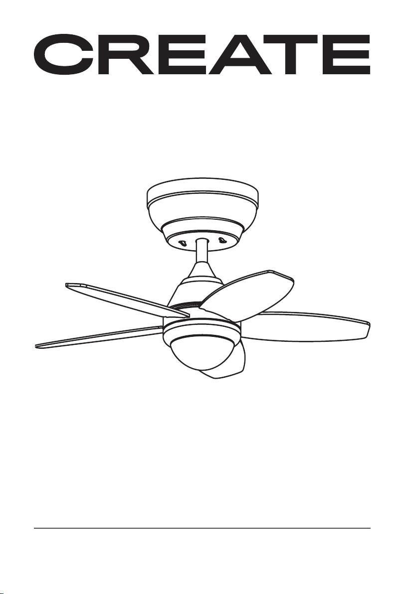
FLOWOOD STYLANCE
CEILING FAN
VENTILADOR DE TECHO
USER MANUAL
Page 2

Page 3

Page 4
INDEX
ENGLISH
PARTS LIST 6
INSTALLATION PREPARATION 7
INSTALLATION INSTRUCTIONS 7
SAFETY INSTRUCTIONS 7
PREPARING THE FAN SITE 8
INSTALLING THE HANGER BRACKET 8
ASSEMBLING AND HANGING THE FAN 8
REMOTE CONTROL CONNECTION 9
REMOTE CONTROL 9
CANNOPY ASSEMBLY 10
BLADES ASSEMBLY 10
CONNECTIONS PANEL ASSEMBLY 11
LED LIGHT PANEL AND LAMP SHADE ASSEMBLY 11
CEILING FAN WITH LED LIGHT 11
DECORATIVE COVER ASSEMBLY 12
CHECK THE INSTALLATION 12
CEILING FAN WITHOUT LED LIGHT 12
PORTUGUÊS
LISTA DE PEÇAS 20
PREPARAÇÃO DA INSTALAÇÃO 21
INSTRUÇÕES DE SEGURANÇA 21
INSTRUÇÕES DE INSTALAÇÃO 21
PREPARAÇÃO LOCALIZAÇÃO VENTILADOR 22
INSTALAÇÃO DO SUPORTE DE MONTAGEM 22
MONTAGEM E PENDURA DO VENTILADOR 22
LIGAÇÃO DO COMANDO À DISTÂNCIA 23
COMANDO À DISTÂNCIA 23
MONTAGEM DO FLORÃO 24
MONTAGEM DAS PÁS 24
MONTAGEM DO PATCH PANEL 25
MONTAGEM PAINEL LED E TELA DECORATIVA 25
VENTILADOR DE TETO COM LUZ LED 25
MONTAGEM DA TAMPA DECORATIVA 26
VERIFIQUE A INSTALAÇÃO 26
VENTILADOR DE TETO SEM LUZ LED 26
ESPAÑOL
LISTA DE PARTES 13
PREPARACIÓN DE LA INSTALACIÓN 14
INSTRUCCIONES DE SEGURIDAD 14
INSTRUCCIONES DE INSTALACIÓN 14
PREPARACIÓN UBICACIÓN VENTILADOR 15
INSTALACIÓN DEL SOPORTE DE MONTAJE 15
MONTAJE Y COLGADO DEL VENTILADOR 15
CONEXIÓN DEL MANDO A DISTANCIA 16
MANDO A DISTANCIA 16
MONTAJE DEL FLORÓN 17
MONTAJE DE LAS ASPAS 17
MONTAJE DE LA PLACA DE CONEXIONES 18
MONTAJE PANEL LED Y PANTALLA DECORATIVA 18
VENTILADOR DE TECHO CON LUZ 18
MONTAJE DE LA CUBIERTA DECORATIVA 19
COMPROBACIÓN DE LA INSTALACIÓN 19
VENTILADOR DE TECHO SIN LUZ 19
FRANÇAIS
LISTE DES PIÈCES 27
PRÉPARATION DE L’INSTALLATION 28
CONSIGNES DE SÉCURITÉ 28
CONSIGNES D’INSTALLATION 28
PRÉPARATION DU VENTILATEUR 29
INSTALLATION DU SUPPORT 29
MONTAGE ET ACCROCHAGE DU VENTILATEUR 29
CONNEXION DE LA TÉLÉCOMMANDE 30
TÉLÉCOMMANDE 30
MONTAGE DU FLEURON 31
MONTAGE DES PALES 31
MONTAGE DU PANNEAU DE BRASSAGE 32
MONTAGE PANNEAU LED ET L’ÉCRAN DÉCORATIF 32
VENTILATEUR DE PLAFOND AVEC LUMIÈRE LED 32
ASSEMBLAGE DU COUVERCLE DÉCORATIF 33
VÉRIFIEZ L’INSTALLATION 33
VENTILATEUR DE PLAFOND SANS LUMIÈRE LED 33
4
Page 5
INDEX
ITALIANO
ELENCO DELLE PARTI 34
PREPARAZIONE DELL’INSTALLAZIONE 35
ISTRUZIONI DI SICUREZZA 35
ISTRUZIONI DI INSTALLAZIONE 35
PREPARAZIONE POSIZIONAMENTO VENTILATORE 36
INSTALLAZIONE DEL SUPPORTO DI MONTAGGIO 36
MONTAGGIO E ATTACCATURA DEL VENTILATORE 36
COLLEGAMENTO DEL TELECOMANDO 37
TELECOMANDO 37
MONTAGGIO DELLA COPPA SUPERIORE 38
MONTAGGIO DELLE PALE 38
MONTAGGIO DEL PANNELLO PATCH 39
MONTAGGIO PANNELLO LED E SCHERMO DECORATIVO 39
VENTILATORE DA SOFFITTO CON LUCE LED 39
ASSEMBLAGGIO DELLA COPERTURA DECORATIVA 40
CONTROLLA L’INSTALLAZIONE 40
VENTILATORE DA SOFFITTO SENZA LUCE LED 40
NEDERLANDS
LIJST MET ONDERDELEN 48
INSTALLATIE VOORBEREIDING 49
VEILIGHEIDSINSTRUCTIES 49
INSTALLATIE INSTRUCTIES 49
DE LOCATIE VAN DE VENTILATOR VOORBEREIDEN 50
MONTAGEBEUGEL INSTALLATIE 50
MONTAGE EN OPHANGEN VAN DE VENTILATOR 50
AFSTANDSBEDIENING VERBINDING 51
AFSTANDSBEDIENING 51
MONTAGE VAN DE ROZET 52
DE MESSEN IN ELKAAR ZETTEN 52
MONTAGE VAN HET PATCHPANEEL 53
MONTAGE VAN LED PANEEL EN DECORATIEVE SCHERM 53
PLAFONDVENTILATOR MET LED-LICHT 53
DE DECORATIEVE HOES MONTEREN 54
CONTROLEER DE INSTALLATIE 54
PLAFONDVENTILATOR ZONDER LED-LICHT 54
DEUTSCH
TEILELISTE 41
VORBEREITUNG DER INSTALLATION 42
SICHERHEITSANWEISUNGEN 42
INSTALLATIONSANWEISUNGEN 42
VORBEREITUNG AUFHÄNGUNGSSTELLE VENTILATORS 43
ANBRINGEN DER MONTAGEHALTERUNG 43
MONTAGE UND AUFHÄNGUNG VENTILATORS 43
ANSCHLUSS DER FERNBEDIENUNG 44
FERNBEDIENUNG 44
ANBRINGEN DER ROSETTE 45
ANBRINGEN DER FLÜGEL 45
MONTAGE DES PATCHPANELS 46
MONTAGE LED-PANELS — DEKORATIVEN BILDSCHIRMS 46
DECKENVENTILATOR MIT LED-LICHT 46
ZUSAMMENBAU DER DEKORATIVEN ABDECKUNG 47
ÜBERPRÜFEN SIE DIE INSTALLATION 47
DECKENVENTILATOR OHNE LED-LICHT 47
POLSKI
WYKAZ CZĘŚCI 55
PRZYGOTOWANIE DO INSTALACJI 56
INSTRUKCJE BEZPIECZEŃSTWA 56
INSTRUKCJE INSTALACJI 56
PRZYGOTOWANIE LOKALIZACJI WENTYLATORA 57
MONTAŻ WSPORNIKA MONTAŻOWEGO 57
MONTAŻ I ZAWIESZANIE WENTYLATORA 57
POŁĄCZENIE ZDALNEGO STEROWANIA 58
ZDALNE STEROWANIE 58
MONTAŻ ROZETY 59
MONTAŻ OSTRZY 59
MONTAŻ PANELU KROSOWEGO 60
MONTAŻ PANELU LED I EKRANU DEKORACYJNEGO 60
WENTYLATOR SUFITOWY Z OŚWIETLENIEM LED 60
MONTAŻ OZDOBNEJ OSŁONY 61
SPRAWDŹ INSTALACJĘ 61
WENTYLATOR SUFITOWY BEZ ŚWIATŁA LED 61
5
Page 6
ENGLISH
Thank you for choosing our ceiling fan. Before using the appliance, and to ensure the best
use, carefully read these instructions.
The safety precautions enclosed herein reduce the risk of death, injury and electrical shock
when correctly adhered to. Keep the manual in a safe place for future reference, along with
the completed warranty card, purchase receipt and package. If applicable, pass these instructions on to the next owner of the appliance. Always follow basic safety precautions and
accident-prevention measures when using an electrical appliance. We assume no liability for
customer failing to comply with these requirements.
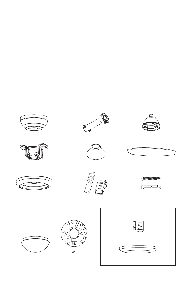
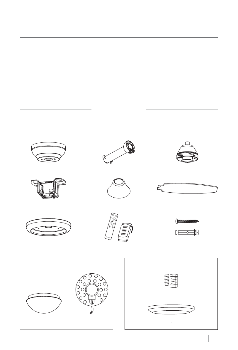
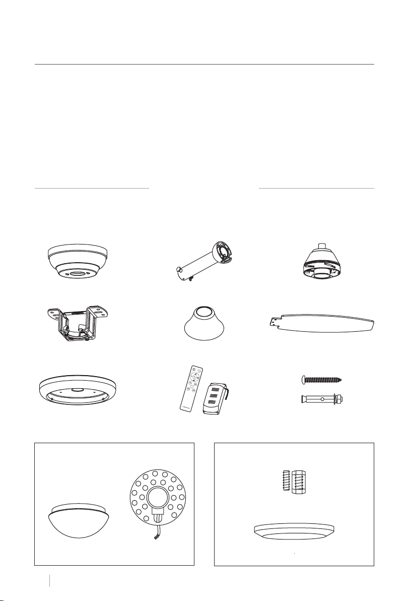
PARTS LIST
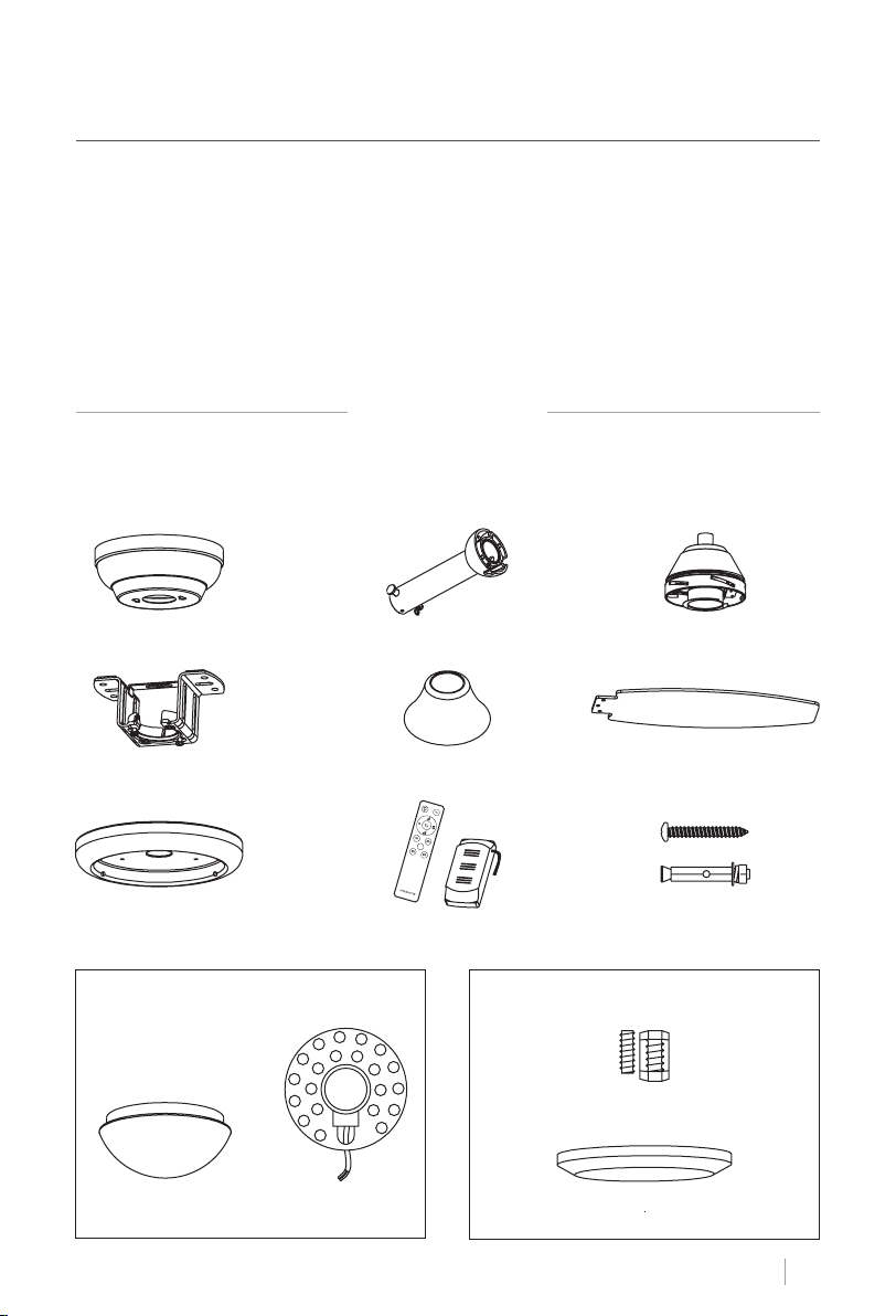
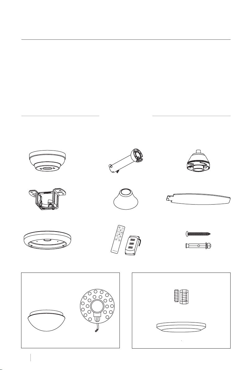
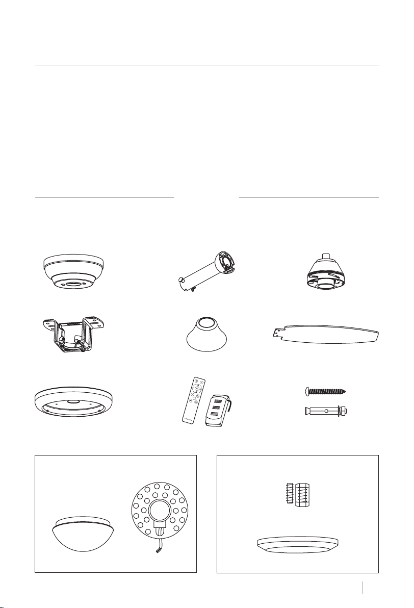
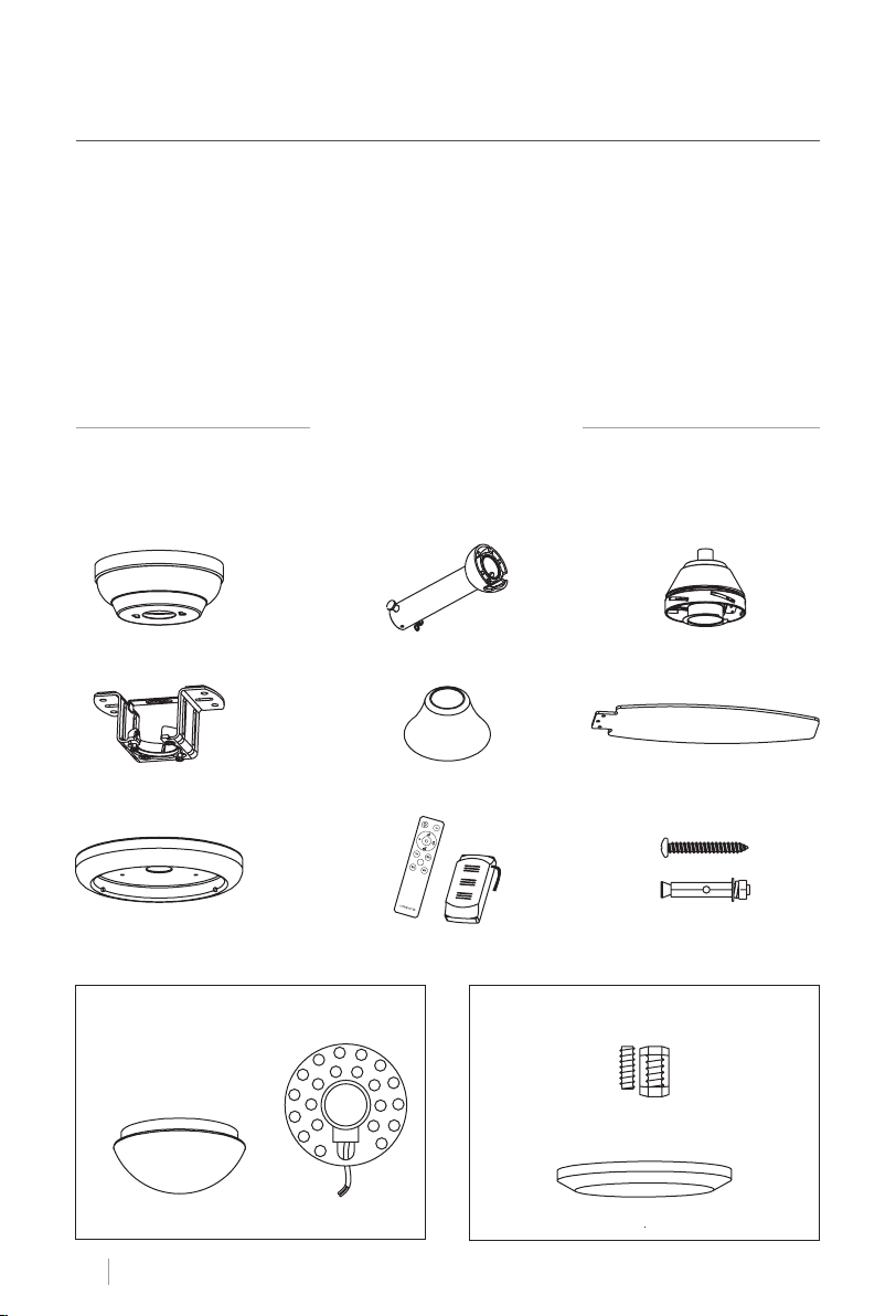
Carefully open the packaging and remove all the items included. Place them on a carpet or
a big piece of plastic to avoid any damage. Check that all the items listed below have been
included.
Canopy Downrod and hanging ball
Mounting Bracket Decorative cover
Connections panel
Option with light:
ENGLISH
6
LED panelDecorative shade
Remote control Expansion screws
Motor
Blades
Option without light:
Fixing screws
Decorative cover
Page 7
SAFETY INSTRUCTIONS
When using any electrical appliance, basic safety precautions should always be observed.
Read this entire manual carefully before beginning installation. Save this instructions.
• Use only original replacement parts.
• To reduce the risk of personal injury, attach the fan directly to the support structure of the
building according to these instructions, and use only the hardware supplied.
• To avoid possible electrical shock, before installing your fan, disconnect the power by turning off the circuit breakers to the outlet box and associated wall switch location. If you
cannot lock the circuit breakers in the off position, securely fasten a prominent warning
device, such as a tag, to the service panel.
• All wiring must be in accordance with national and local electrical codes and ANSI/NFPA
70. If you are unfamiliar with wiring, use a qualied electrician.
• To reduce the risk of personal injury, do not bend the blade attachment system when installing, balancing, or cleaning the fan.
• Never insert foreign objects between rotating fan blades.
• To reduce the risk of re, electrical shock, or motor damage, do not use a solid-state speed
control with this fan. Use only original speed controls.
• This appliance can be used by children aged from 8 years old and above and persons with
reduced physical, sensory or mental capabilities or lack of experience and knowledge if
they have been given supervision or instruction concerning use of the appliance in a safe
way and understand the hazards involved. Children shall not play with the appliance. Cleaning and user maintenance shall not be made by children unless they are older than 8 and
supervised. Close supervision is necessary when any appliance is used by or near children.
NOTE: The important safety precautions and instructions appearing in the manual are not
meant to cover all possible conditions and situations that may occur. It must be understood
that common sense and caution are necessary factors in the installation and operation of
this fan.
INSTALLATION INSTRUCTIONS
• Mark the correct position of the holes and x the ceiling bracket using the screws with
metal anchor or screws and washers suitable for the type of ceiling chosen.
• Check the correct installation of the bracket before hanging the fan. This plate must support the full weight of the fan.
INSTALLATION PREPARATION
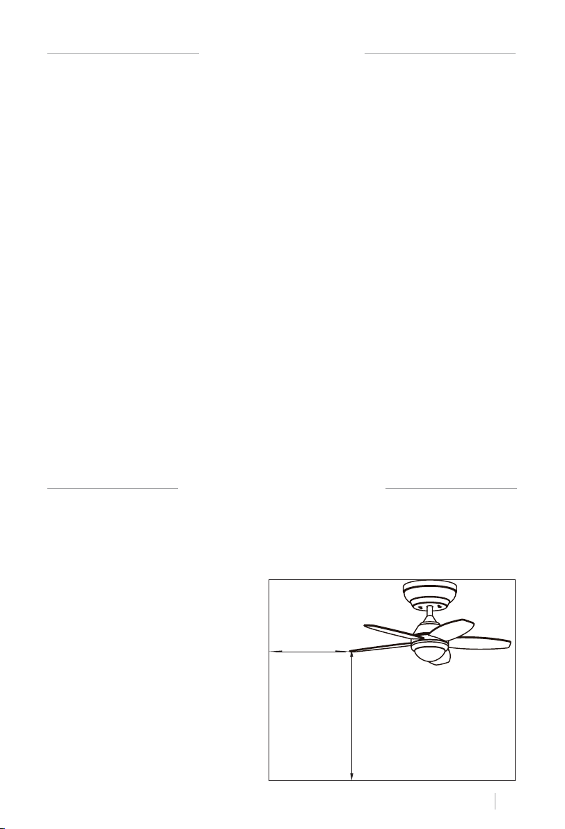
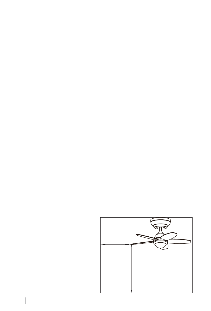
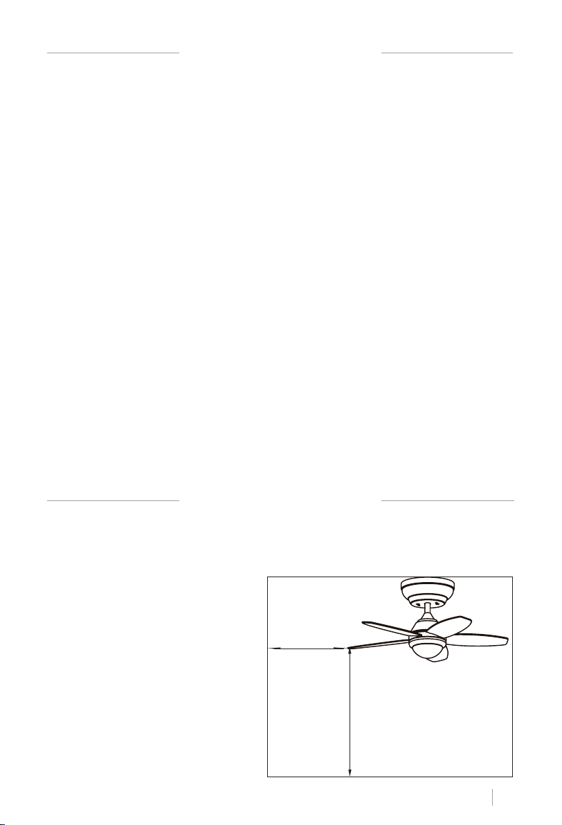
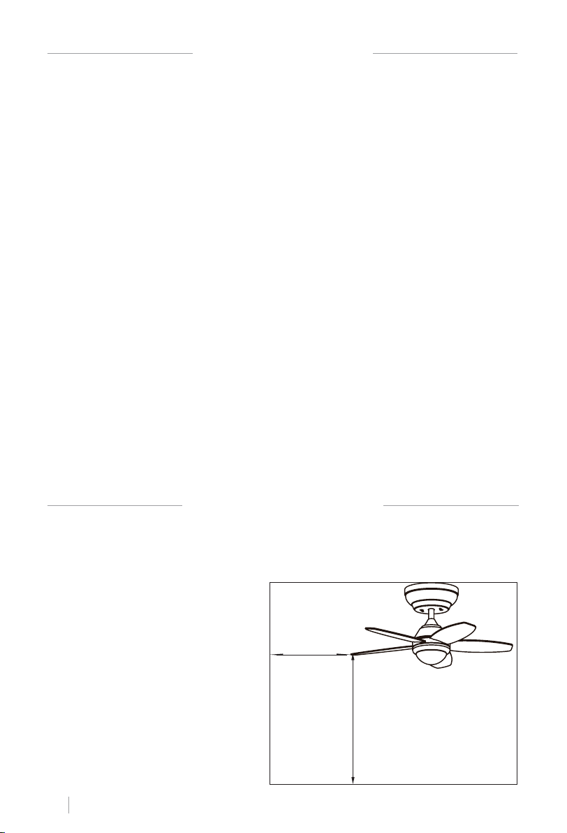
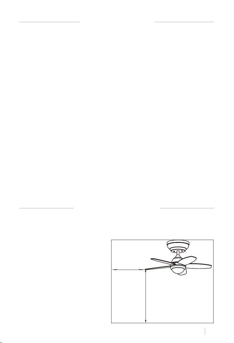
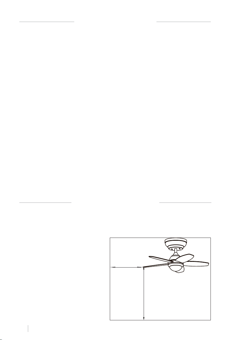
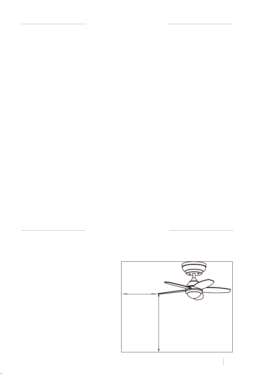
• To prevent personal injury and damage, ensure that the hanging location
allows the blades a clearance of 2.3
m from the oor and 76 cm from any
wall or obstruction.
• Be sure the outlet box is securely attached to the building structure and
can support the full weight of the fan.
76 cm
from wall
or nearest
obstruction
2.3 m from
blades to
oor
ENGLISH
7
Page 8
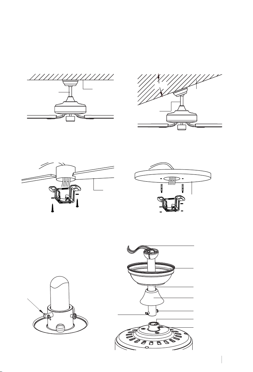
PREPARING THE FAN SITE
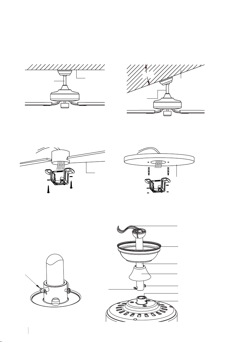
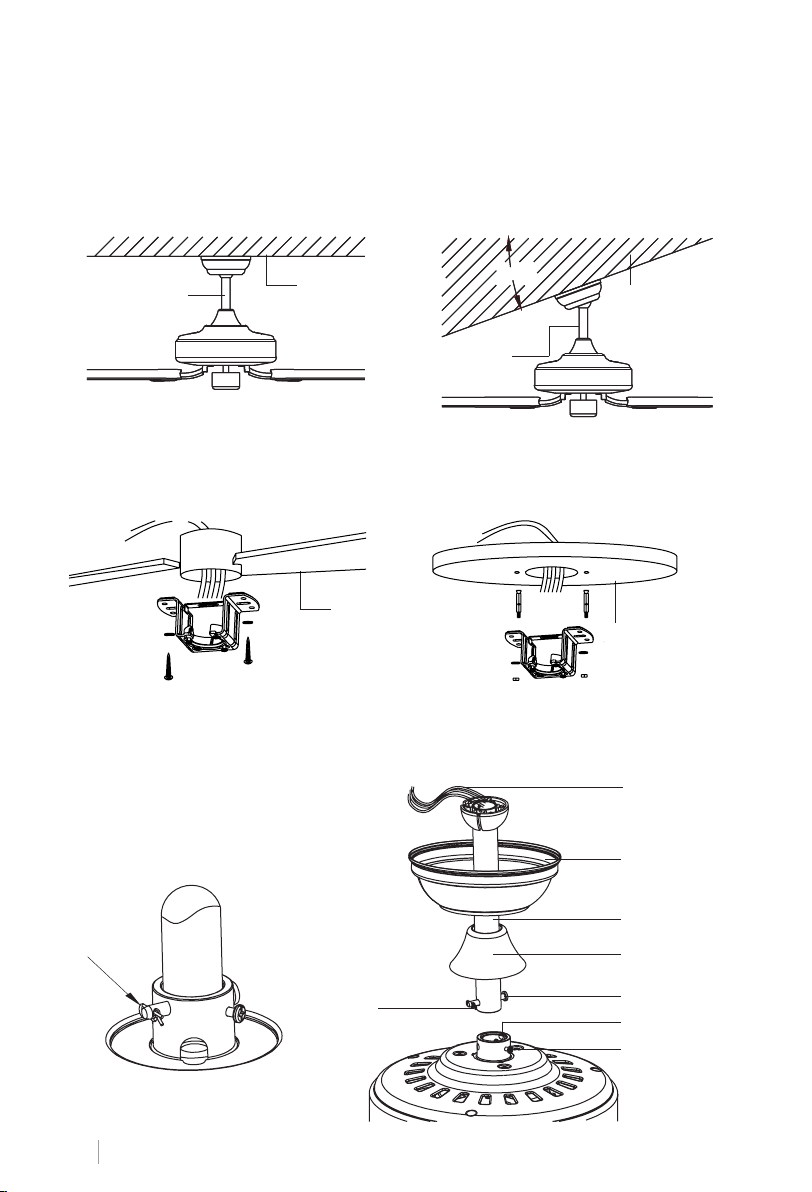
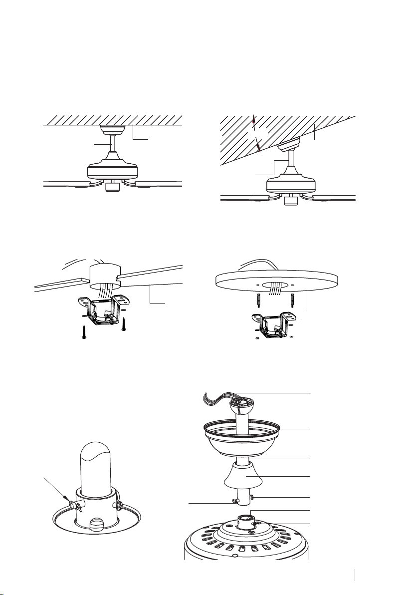
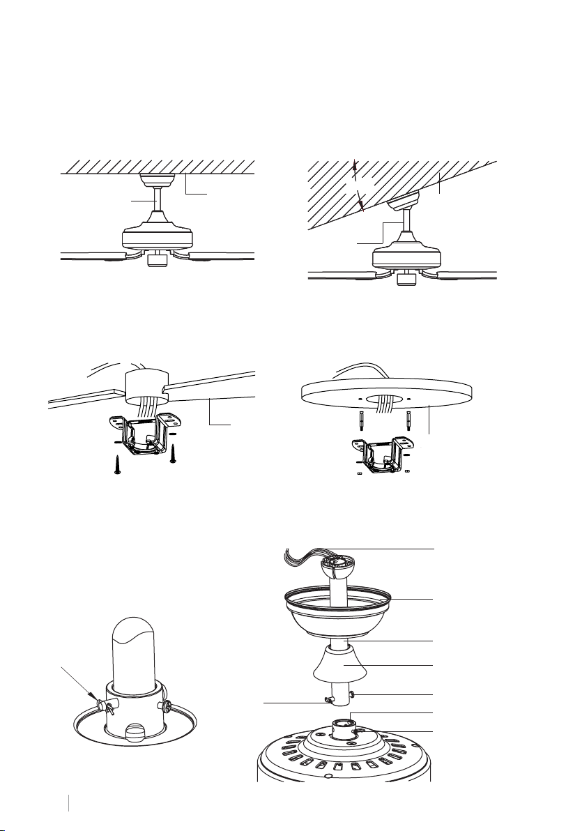
Choose the suspension bar that best suits your situation: it has a 15 cm and a 25 cm suspension bar.
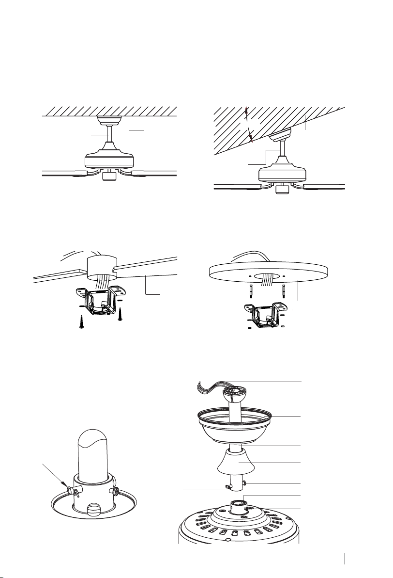
Remove the bar bolt, removing the pin, and pass the canopy (roof trim) and the engine canopy through the suspension bar. Next, route the fan motor cables through the inside of the
suspension bar. Tighten the suspension bar to the engine and insert the bolt and pin.
Standard
mounting style
Support brace
Standard Mounting hangs from the ceiling by a downrod.
Angled Mounting recommended for a
vaulted or angled ceiling.
20°20°20°20°
Support
brace
Angled
mounting
style
INSTALLING THE HANGER BRACKET
Wood ceiling
Concrete ceiling
Please, drill an 8 mm in diametre hole on the concrete ceiling, and insert the bolt. Then, align
the bracket with the hole and tighten with a nut.
ASSEMBLING AND HANGING THE FAN
Electrical wiring
8
Cotter pin
ENGLISH
Cotter pin
Canopy
Hanging ball slot
Decorative cover
Bolt
Adapter
Fixing screw
Page 9
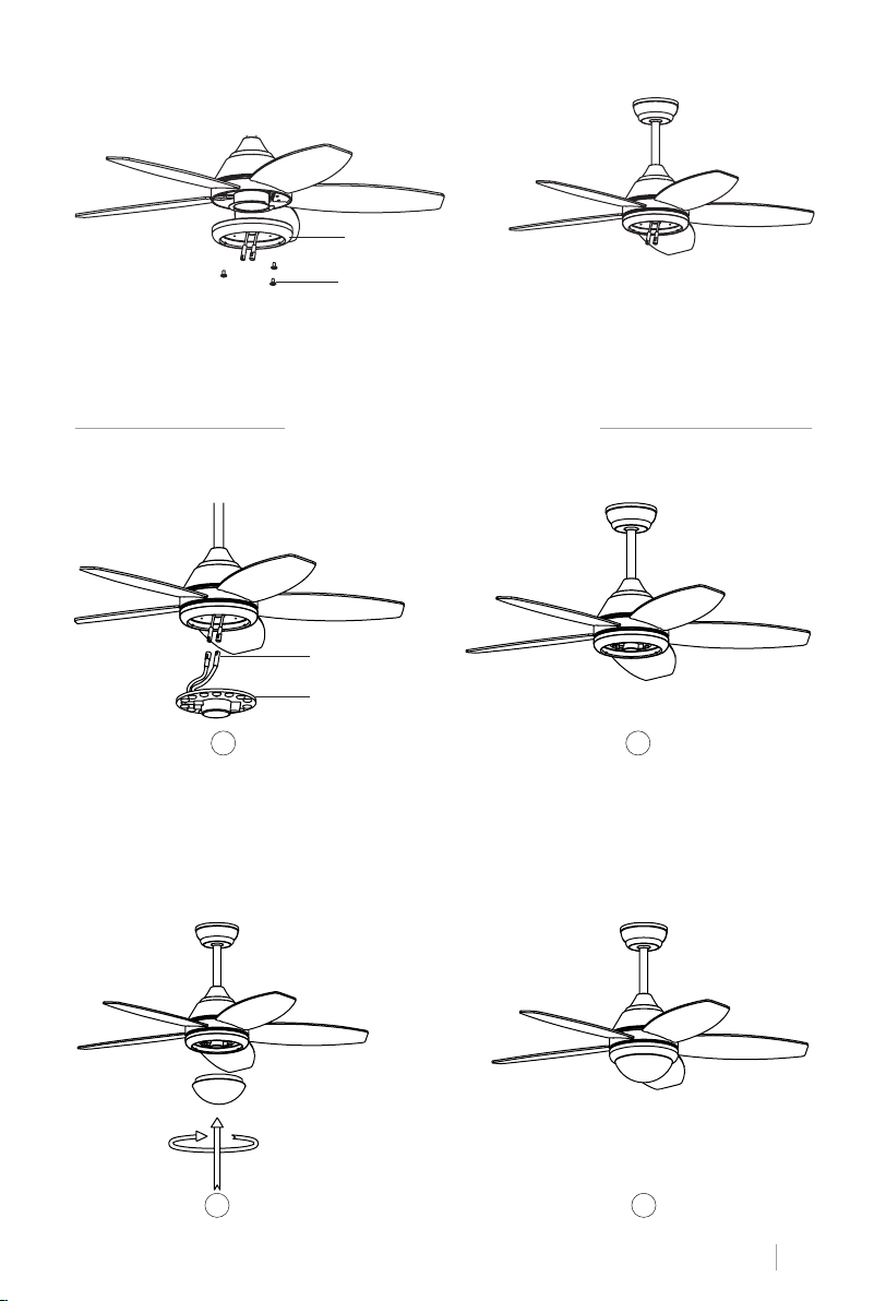
Tip: To prepare for threading electrical wires through the downrod, apply a small piece of
electrical tape to the ends of the electrical wires. This will keep the wires together when
threading them through the downrod.
• Loosen the xing screws and nut at the top of the motor housing. Remove the pin and bolt
from the downrod (if you have not already done so). Slide the downrod through the canopy.
• Tread electrical wires through the downrod and pull extra wire slack from the upper end
of the downrod.
• Place the downrod into the motor housing yoke and reinsert the pin and bolt that were
previously removed. Tighten the xing screws and nut securely.
• Lower the canopy to the motor housing.
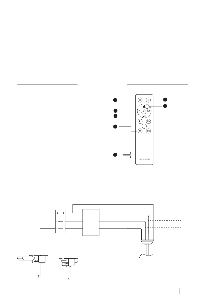
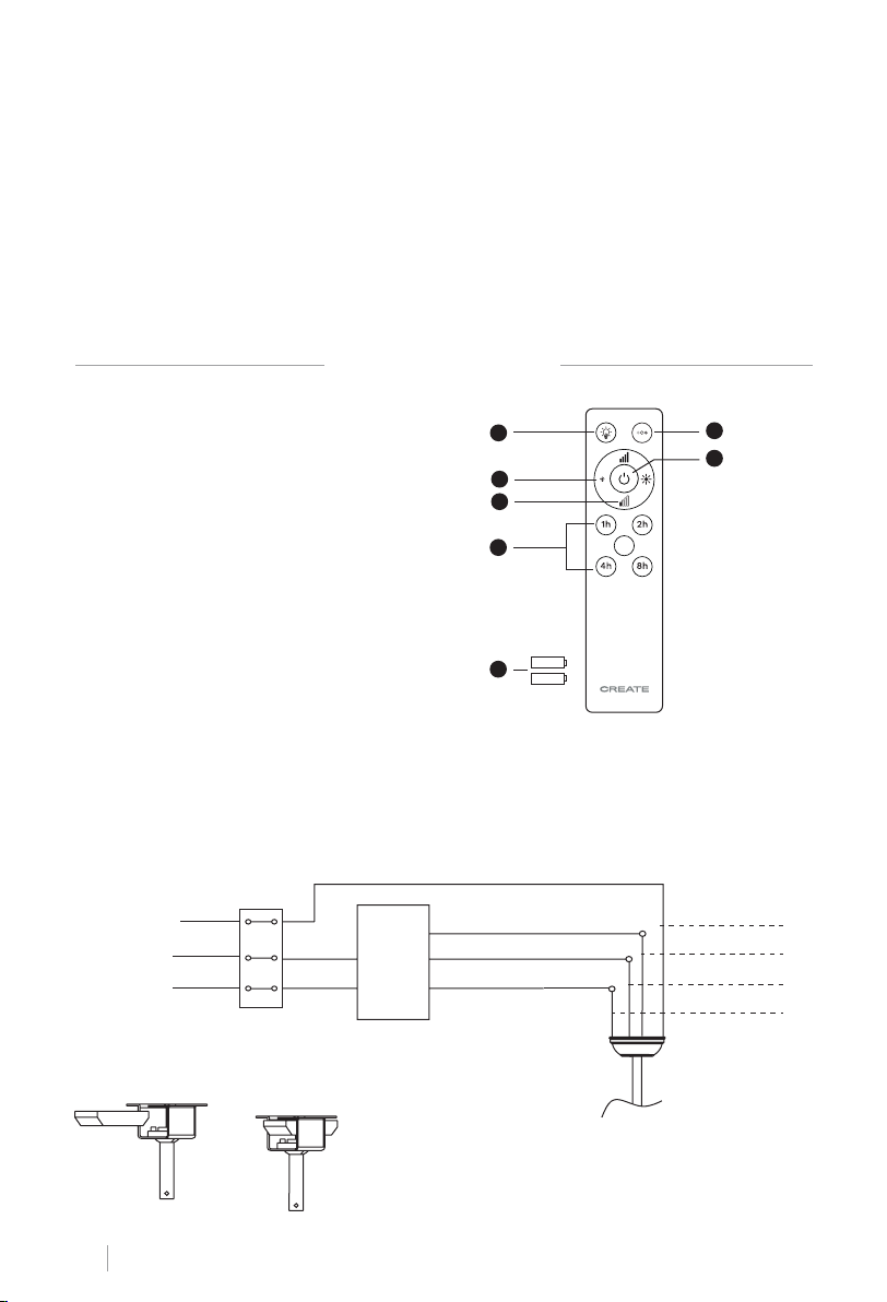
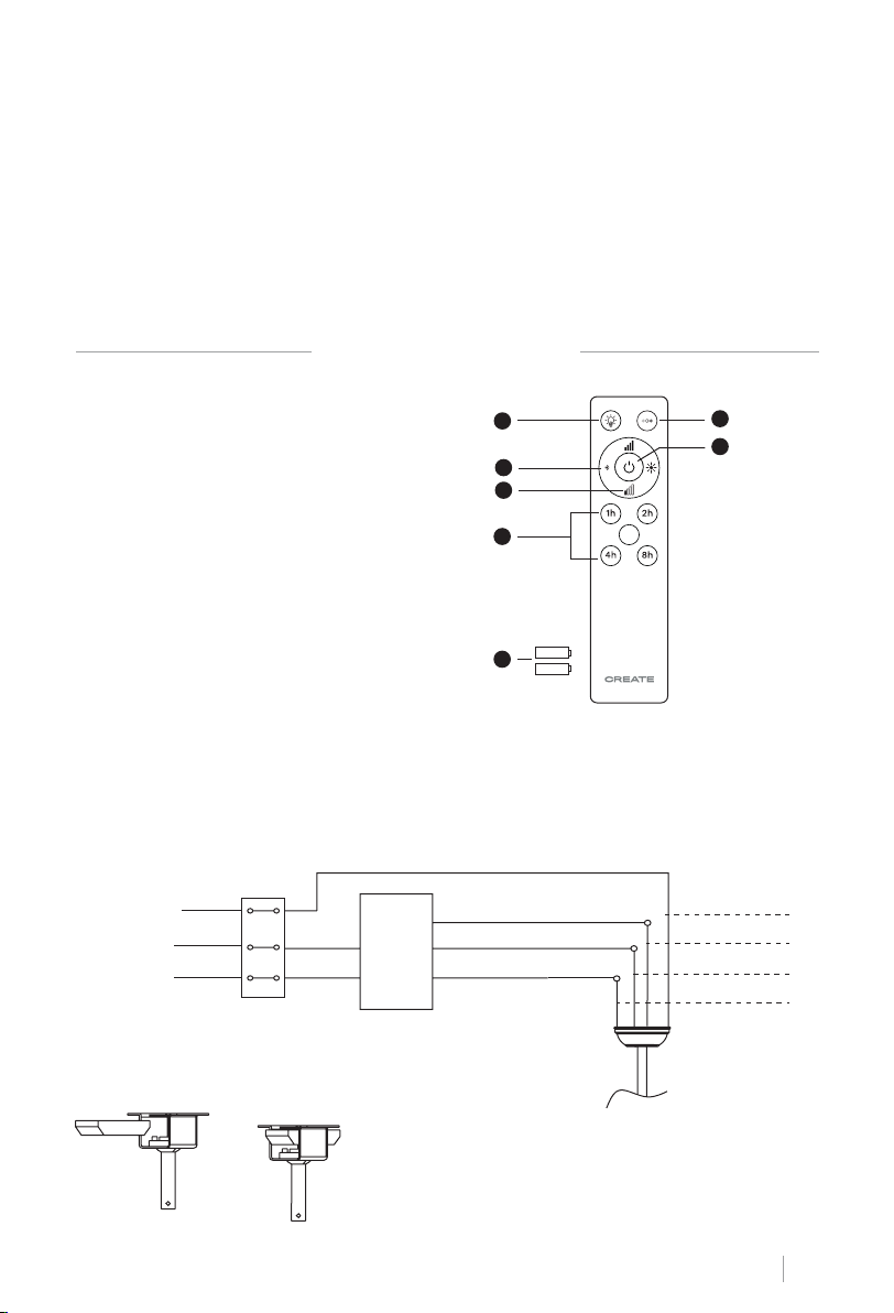
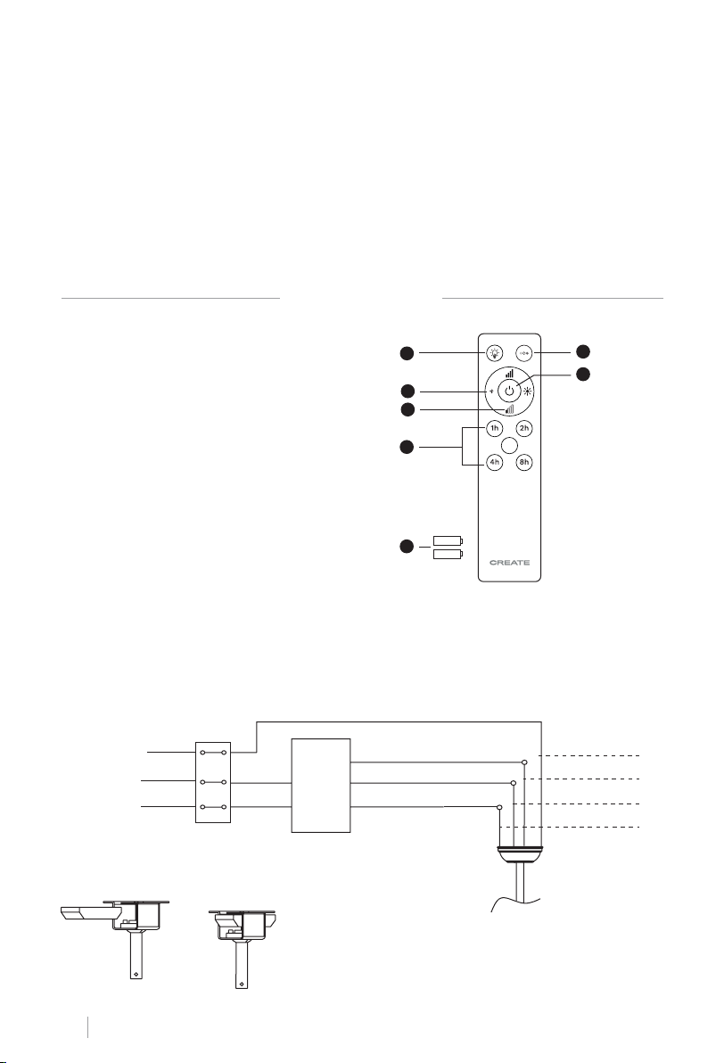
REMOTE CONTROL
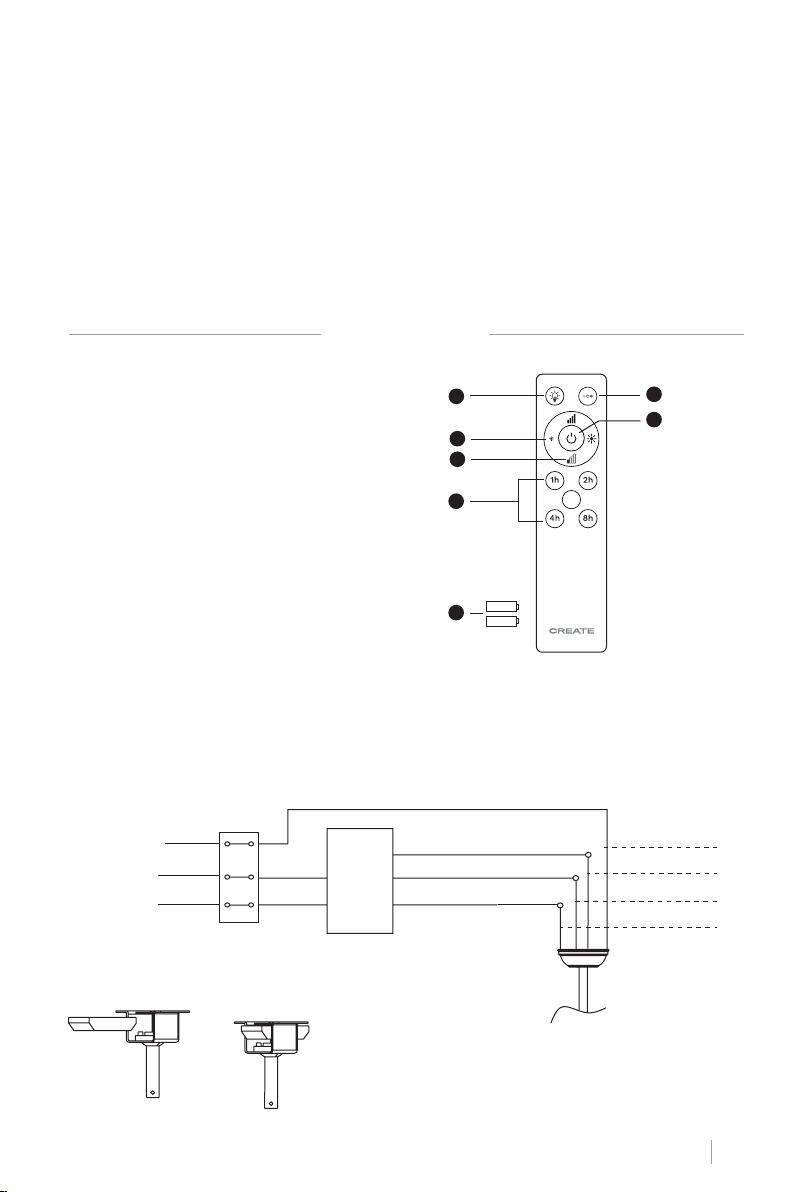
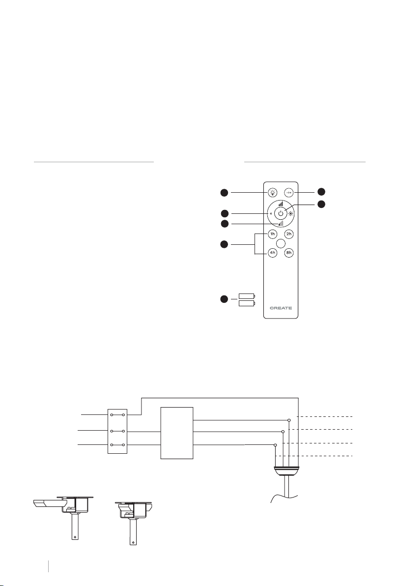
1. **Light
2. **Light intensity control
3. Fan intensity control
4. Timer
5. Batteries (2 x AAA)
6. **Colour temperature control
1
2
3
4
6
7
7. ON / OFF button
** Function only available when having
the LED plate installed.
5
REMOTE CONTROL CONNECTION
Make the connection between the receiver cables and the fan motor cables following the
color indications. Make sure the connection is tight.
Ground wire
AC
Light L
L
N
Input L
Input N
Remote
control
receiver
Fan L
Neutral N
Ground wire
Light L
Motor L
Neutral N
Remote control receiver placement:
ENGLISH
9
Page 10
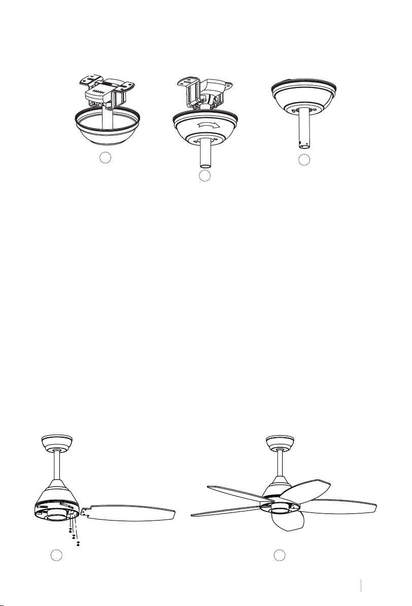
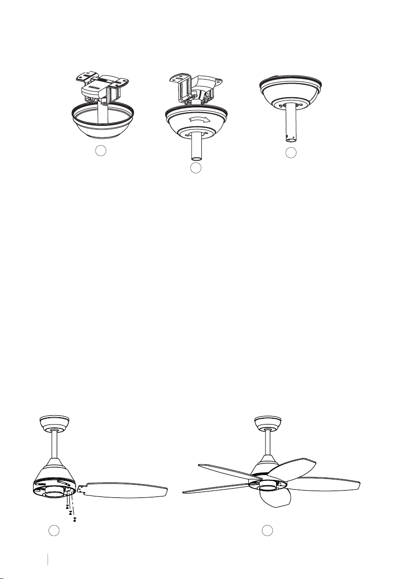
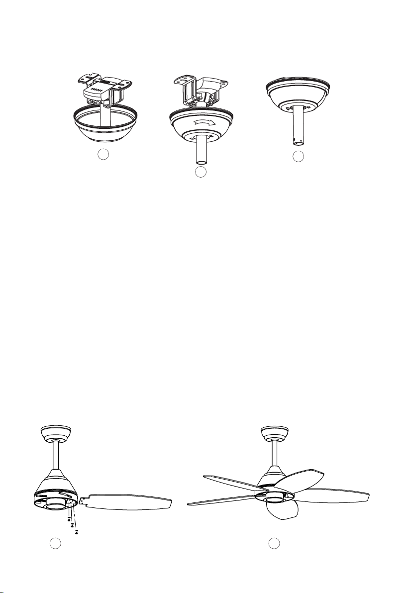
CANNOPY ASSEMBLY
1
3
2
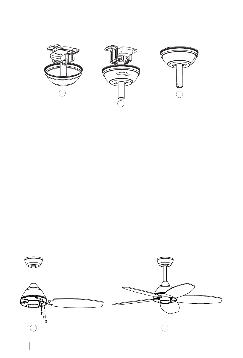
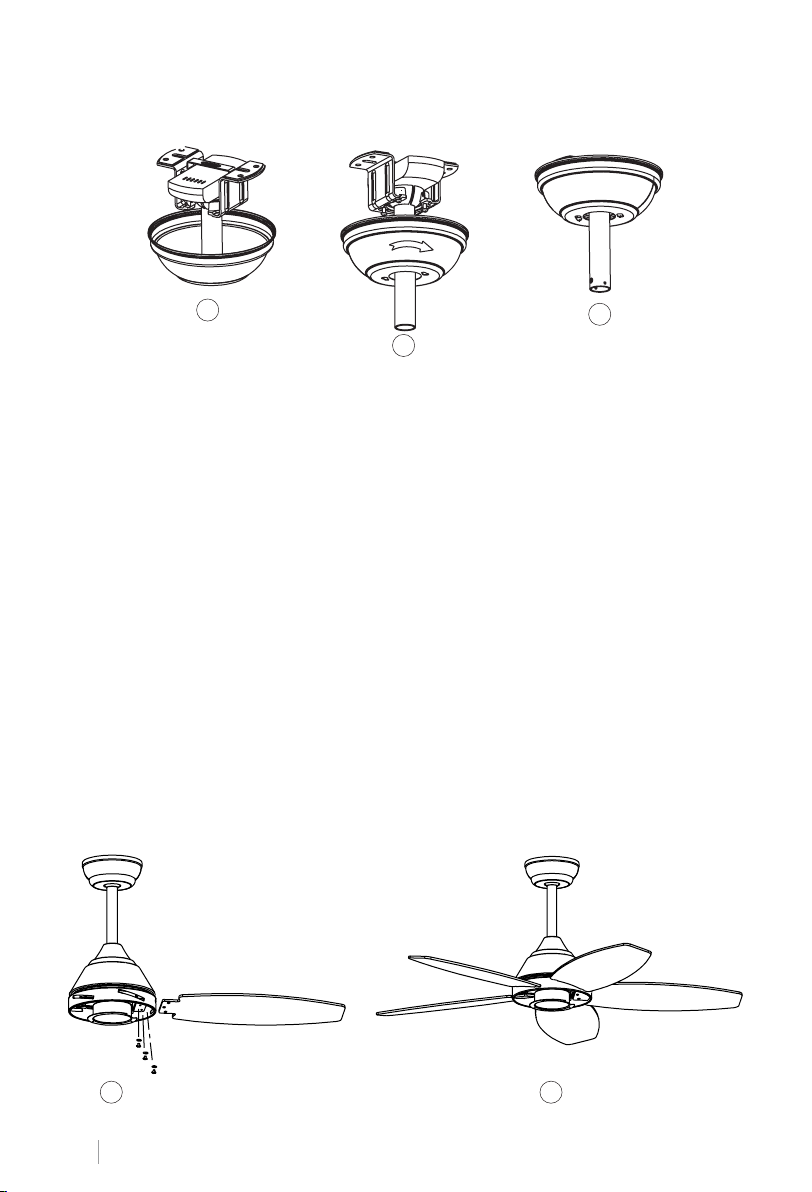
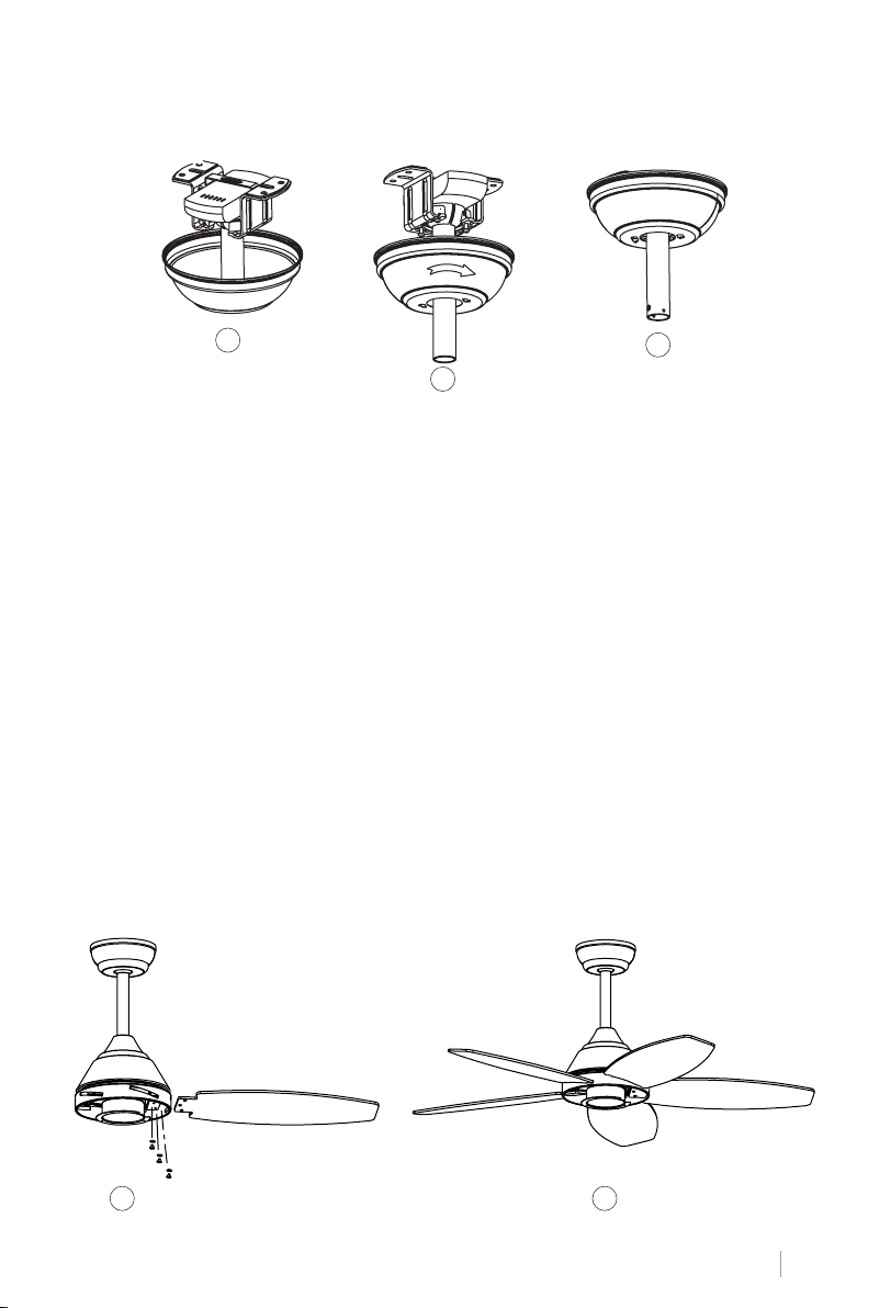
• Raise the canopy to hanging bracket, aligning loosened screws in hanging bracket with
slotted holes in the canopy.
• Twist the canopy to lock. Re-insert the screws and secure all the screws with a screwdriver.
• With hanging bracket secured to the outlet box and able to support the fan, you are now
ready to hang your fan.
• Grab the fan rmly with two hands. Slide downrod through the opening in the hanging
bracket and let the hanging ball rest on the hanging bracket.
• Turn the hanging ball slot until it lines up with the hanging bracket tab.
Tip: Seek the help of another person to hold the stepladder in place and to lift the fan up to
you once you are set on the ladder.
BLADES ASSEMBLY
Align the holes on the blade holder with the holes on the blades and the motor body and
screw them in place, but don’t tighten them until they are all placed and screwed in.
Tip: To save time, you can t the washers on each screw prior to installing the blades.
1 2
ENGLISH
10
Page 11
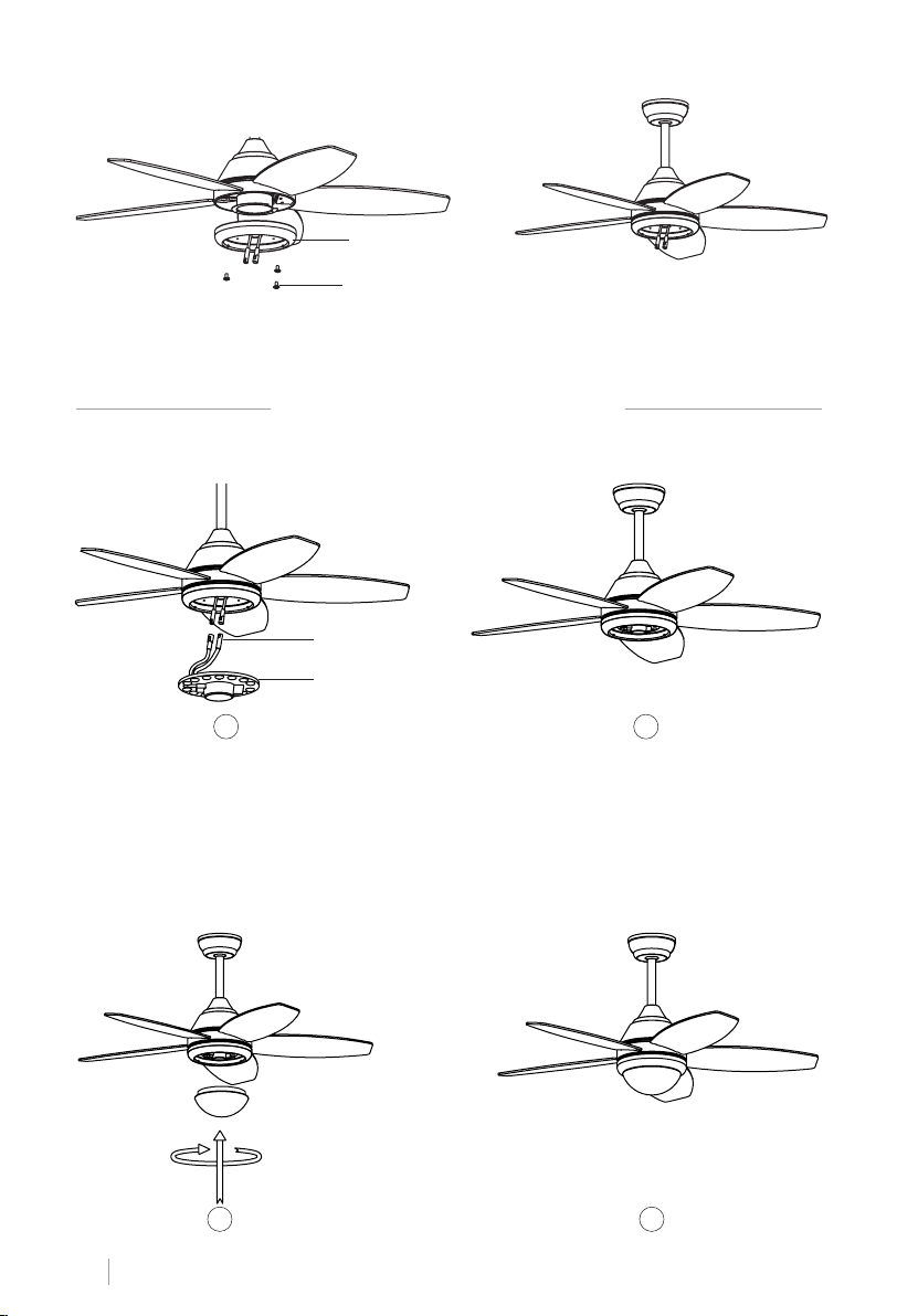
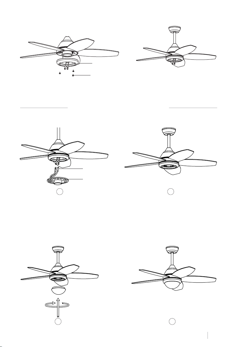
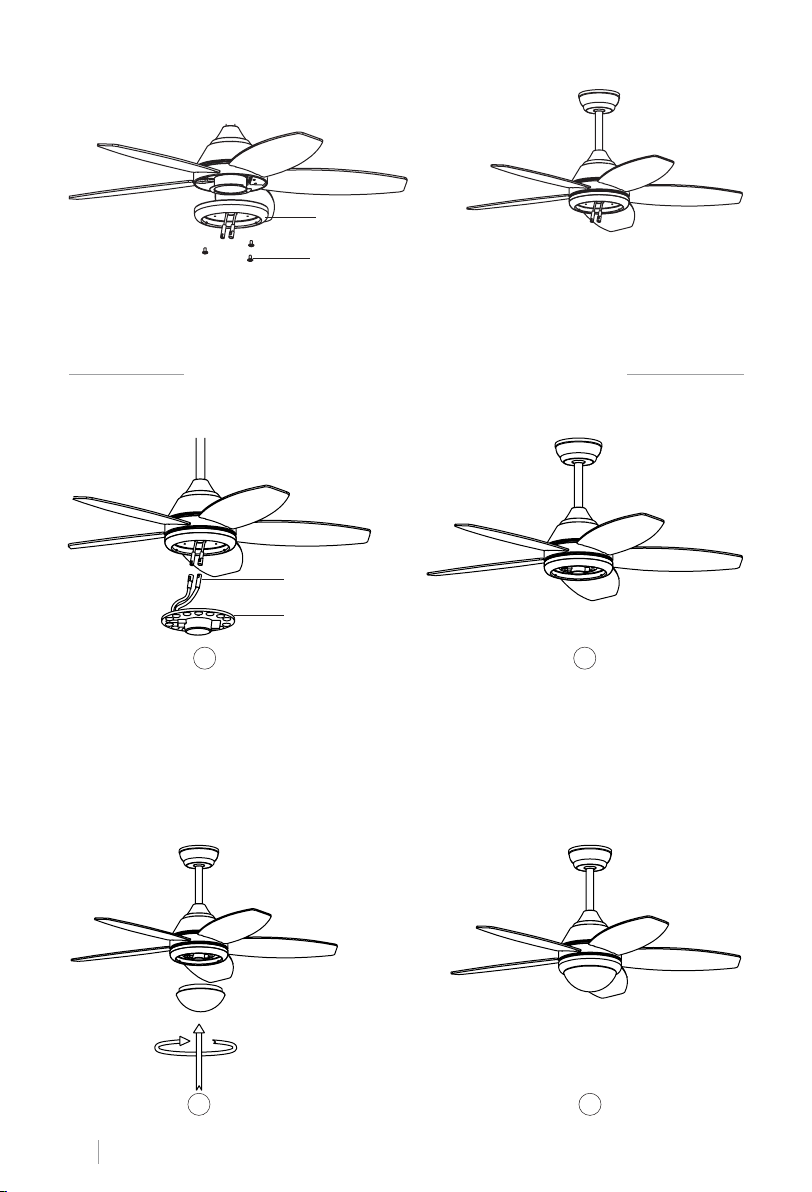
CONNECTIONS PANEL ASSEMBLY
Connections panel
Connections panel screw
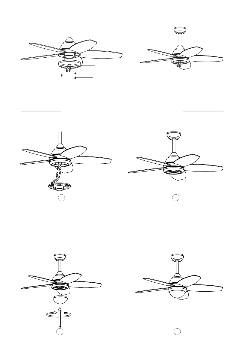
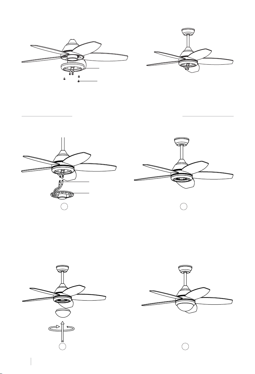
Attach the connections plate up to the bottom of the fan by inserting the set screw heads
into the key hole slots. Rotate them to place and tighten them to secure the plate.
CEILING FAN WITH LED LIGHT
LED LIGHT PANEL AND LAMP SHADE ASSEMBLY
Single-pin plug
LED
1 2
Connect the single-pin plugs of the connections plate with the ones on the LED panel. The LED
panel is magnetized so it will be attached to the connections panel just by placing them together.
Note: While installing or removing the LED plate, please keep the insulation pads intact carefully. Turning the set screws over-tightly or fast will damage the insulation pads.
Screw the lamp shade back to the connections plate.
3 4
ENGLISH
11
Page 12
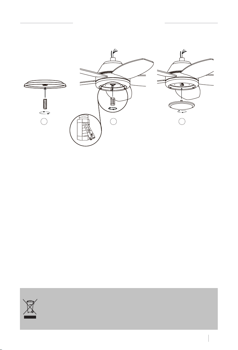
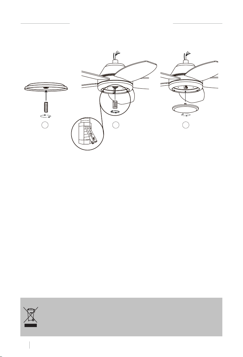
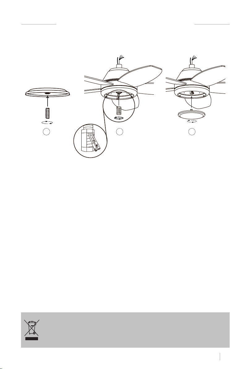
CEILING FAN WITHOUT LED LIGHT
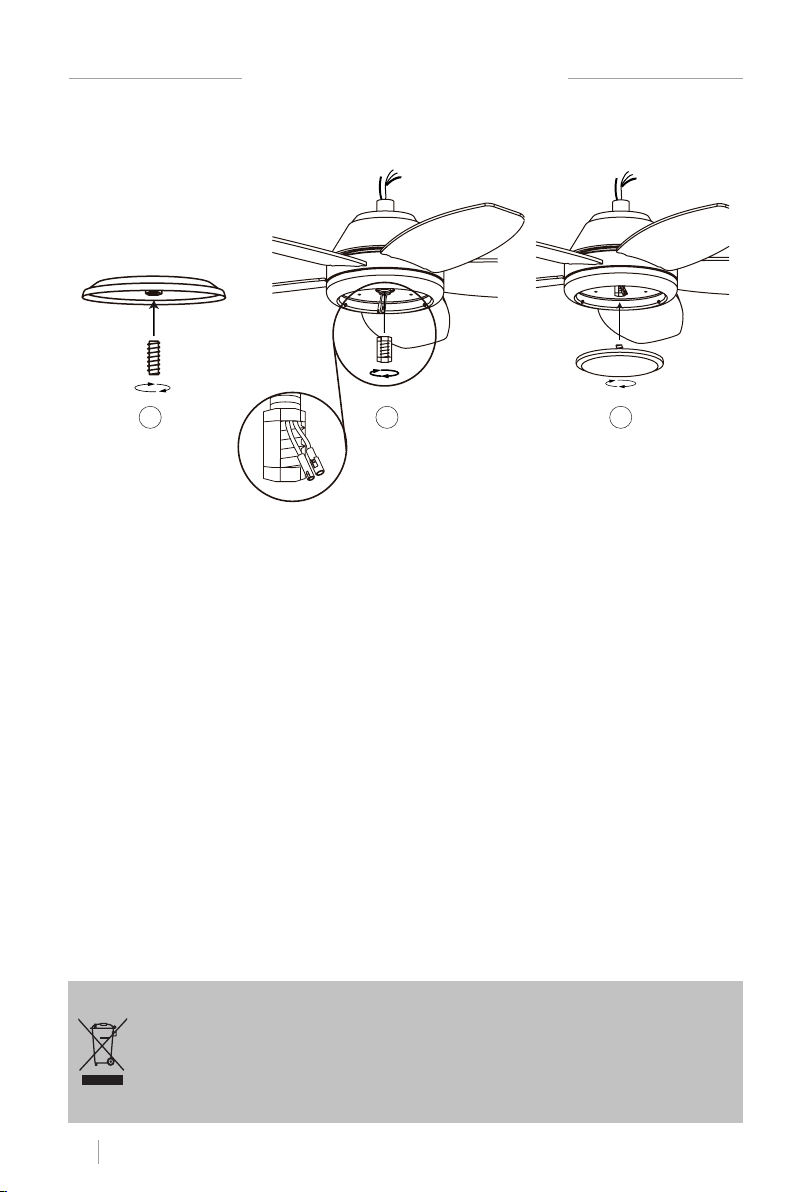
DECORATIVE COVER ASSEMBLY
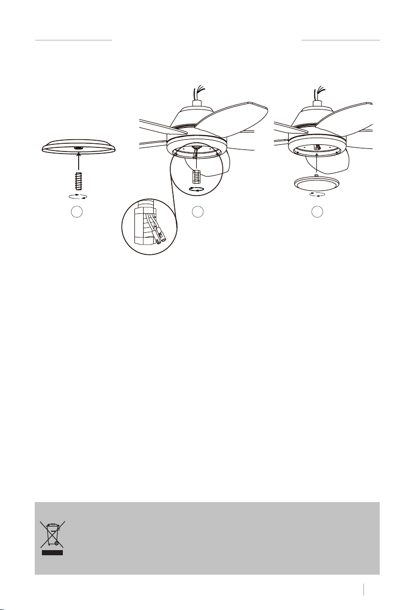
1 2 3
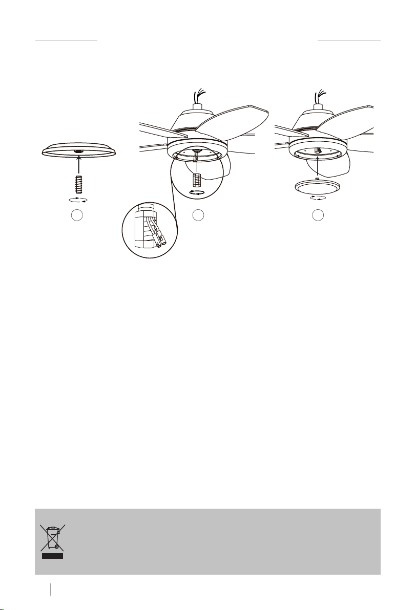
Once the connections plate has been assembled and secured, screw the decorative cover
back to the connections plate using the central screw.
CHECK THE INSTALLATION
• Check the correct operation of the ceiling fan, checking that no strange movement or
misalignment is observed in any part of the fan.
• In the event that some kind of hum / vibration can be seen, you can proceed to adjust the
blades with the shooting kit.
• This kit has self-adhesive weights and "u" shaped clips.
• Turn off the ceiling fan.
• You can put the clip in the center of any blade and check if the vibration decreases.
• Turn on the fan and check. If no change is seen, turn off the fan and add another clip to a
different blade or use the adhesive weights.
In compliance with Directives: 2012/19/EU and 2015/863/EU on the restriction of the use of dangerous substances in electric and electronic equipment as well as their waste disposal. The symbol with the crossed dustbin shown on the package
indicates that the product at the end of its service life shall be collected as separate waste. Therefore, any products that
have reached the end of their useful life must be given to waste disposal centres specialising in separate collection of
waste electrical and electronic equipment, or given back to the retailer at the time of purchasing new similar equipment,
on a one for one basis. The adequate separate collection for the subsequent start-up of the equipment sent to be recycled,
treated and disposed of in an environmentally compatible way contributes to preventing possible negative effects on the
environment and health and optimises the recycling and reuse of components making up the apparatus. Abusive disposal
of the product by the user involves application of the administrative sanctions according to the laws.
ENGLISH
12
Page 13
ESPAÑOL
Gracias por elegir nuestro ventilador de techo. Antes de utilizar este electrodoméstico y para
asegurar su mejor uso, por favor, lea detenidamente las instrucciones.
Las medidas de seguridad aquí indicadas reducen el riesgo de incendio, descarga eléctrica y
lesiones cuando se siguen correctamente. Guarde el manual en un lugar seguro para futuras
referencias, así como la garantía, el recibo de compra y la caja. Si procede, entregue estas instrucciones al futuro propietario del electrodoméstico. Siempre siga las instrucciones básicas de seguridad y las medidas de prevención de riesgos cuando utilice un electrodoméstico
eléctrico. El fabricante no se responsabilizará de ningún daño derivado del incumplimiento
de estas instrucciones por parte del usuario.
LISTA DE PARTES
Abra con cuidado el embalaje y retire las piezas que se incluyen en su interior. Colóquelas
en el suelo sobre una alfombra o un trozo de plástico lo sucientemente grande para evitar
cualquier daño. Compruebe que los objetos que se detallan a continuación se encuentran en
el interior del embalaje.
Florón Barra de suspensión con bola
Soporte de montaje Embellecedor
Panel de conexiones
Opción con luz:
Panel LEDPantalla decorativa
Mando a distancia Tornillos de expansión
Motor
Aspas
Opción sin luz:
Tornillos de jación
Cubierta decorativa
ESPAÑOL
13
Page 14
INSTRUCCIONES DE SEGURIDAD
• Al utilizar cualquier aparato eléctrico, deben observarse siempre las siguientes precauciones básicas de seguridad.
• Lea este manual con detenimiento antes de empezar la instalación. Guarde estas instrucciones.
• Para reducir el riesgo de sufrir cualquier daño personal, acople el ventilador directamente
a la estructura de soporte del edicio siguiendo estas instrucciones y utilice únicamente
el material proporcionado.
• Para evitar posibles descargas eléctricas, antes de instalar su ventilador, desconecte la
corriente apagando los interruptores de potencia del cuadro eléctrico y los interruptores de
pared asociados. Si no es posible apagar los interruptores de potencia, utilice un dispositivo de advertencia como una etiqueta en el cuadro eléctrico.
• Todos los cables deben cumplir las especicaciones establecidas según los códigos eléc-
tricos locales y nacionales y ANSI/NFPA 70. Si no está familiarizado con las instalaciones
eléctricas, acuda a un electricista cualicado.
• No doble el sistema de acoplamiento de las aspas mientras las instala, las inclina o las limpia.
• No inserte otros objetos entre las aspas del ventilador.
• Para reducir el riesgo de incendio, descarga eléctrica o daño en el motor, no utilice un regulador de velocidad de estado sólido con este ventilador. Utilice únicamente los reguladores
de velocidad originales.
• Este electrodoméstico puede ser utilizado por niños de 8 años en adelante y personas con
capacidades físicas, sensoriales o mentales reducidas, o con falta de experiencia o conocimientos limitados, siempre que estén supervisados por una persona responsable de su
seguridad o que haya sido formada para usar el aparato de forma segura. Los niños no
deben jugar con este aparato. Tampoco deben realizar tareas de limpieza y mantenimiento
del aparato a menos que sean mayores de 8 años y estén supervisados. Es necesario supervisar a los niños de cerca cuando utilicen cualquier electrodoméstico.
NOTA: Las instrucciones y precauciones de seguridad que aparecen en este manual pueden
no abarcar todos los problemas y situaciones posibles. Debe entender que tanto el sentido
común como la precaución son esenciales para la instalación y el uso del ventilador.
INSTRUCCIONES DE INSTALACIÓN
• Marque la posición correcta de los agujeros y je el soporte de techo utilizando los tornil-
los con anclaje metálico o tornillos y arandelas adecuados al tipo de techo elegido.
• Verique la correcta instalación del soporte antes de colgar el ventilador. Esta placa
debe de soportar todo el peso del ventilador.
PREPARACIÓN DE LA
INSTALACIÓN
• Para evitar daños personales y heridas, asegúrese de que el lugar donde
va a colgar el ventilador permite que
las aspas estén a una distancia igual
o superior a 2,3 m del suelo y 76 cm
de la pared u obstáculo más cercano.
• Asegúrese de que la caja de conexiones está sujetada de manera ade-
cuada a la estructura del edicio y
que puede aguantar todo el peso del
ventilador.
ESPAÑOL
14
76 cm desde la pared
o el obstá-
culo más
cercano
2.3 m
desde las
aspas al
suelo
Page 15
PREPARACIÓN DE LA UBICACIÓN DEL VENTILADOR
Elija la barra de suspensión que más se adapte a su situación: dispone de una barra de suspensión de 15 cm y una de 25cm.
Retire el perno de la barra, quitando el pasador y pase el orón (embellecedor del techo) y
el orón del motor a través de la barra de suspensión. A continuación, pase los cables del
motor del ventilador por el interior de la barra de suspensión. Ajuste la barra de suspensión
al motor e introduzca el perno y el pasador.
Estilo de
montaje
tradicional
Soporte
El montaje tradicional cuelga del techo
con una barra.
El montaje en ángulo se recomienda en
techos inclinados o abovedados.
20°20°20°20°
Soporte
Estilo de
montaje en
ángulo
INSTALACIÓN DEL SOPORTE DE MONTAJE
Techo de
madera
Techo de
hormigón
Taladre un agujero de 8 mm de diámetro en el techo de hormigón e inserte un tornillo.
Después, alinee el soporte con el agujero y fíjelo con una tuerca.
MONTAJE Y COLGADO DEL VENTILADOR
Cableado
Pasador de bloqueo
Pasador de
bloqueo
Florón
Acoplamiento de
la bola
Embellecedor
Perno
Adaptador
Tornillo de
jación
ESPAÑOL
15
Page 16
Consejo: Para facilitar la introducción de los cables en la barra, coloque un poco de cinta
aislante alrededor de los cables. Esto le ayudará a mantenerlos juntos mientras los inserta
en la barra.
• Aoje los tornillos de jación y la arandela de la parte superior de la carcasa del motor.
Retire los pasadores de la barra (si no lo ha hecho aún). Introduzca el orón por la barra.
• Pase los cables por la barra y tire del sobrante de los cables desde la parte superior de
la barra para ajustarlos.
• Coloque la barra dentro de la carcasa del motor e inserte los pasadores que retiró anteri-
ormente. Ajuste los tornillos de jación y las arandelas.
• Baje el orón hacia la carcasa del motor.
MANDO A DISTANCIA
1. **Luz
2. **Control de intensidad de la luz
3. Control de intensidad del ventilador
4. Temporizador
5. Pilas (2 x AAA)
6. **Control de la temperatura de color
1
2
3
4
6
7
7. Botón ON / OFF
** Función solo disponible con la placa
LED instalada.
5
CONEXIÓN DEL MANDO A DISTANCIA
Realice la conexión entre los cables del receptor y los cables del motor del ventilador
siguiendo las indicaciones de color. Asegúrese de que la conexión sea rme.
Toma de tierra
L
AC
N
Entrada
L
Entrada
N
Receptor
mando a
distancia
Luz L
Ventilador L
Neutro N
Toma de tierra
Luz L
Motor L
Neutro N
Colocación del receptor del mando a distancia:
ESPAÑOL
16
Page 17
MONTAJE DEL FLORÓN
1
3
2
• Levante el orón hasta el soporte de montaje y alinee los tornillos aojados en el soporte
de montaje con los oricios del orón.
• Gire el orón para ajustarlo. Reinserte los tornillos y fíjelos con un destornillador.
• Una vez tenga el soporte de montaje asegurado a la caja de conexiones puede proceder a
colgar el ventilador.
• Agarre el ventilador con rmeza con ambas manos. Pase la barra por la apertura del
soporte de montaje y deje que la bola se apoye en el soporte de montaje.
• Gire el acoplamiento de la bola hasta que se alinee con la pestaña del soporte de montaje.
Consejo: Otra persona debería ayudarle para sostener la escalera de mano y alcanzarle el
ventilador una vez se haya subido a la escalera.
MONTAJE DE LAS ASPAS
Alinee los oricios del soporte de las aspas con los oricios de las aspas y del cuerpo del
motor y atorníllelas en su sitio, pero no apriete los tornillos hasta que estén todas colocadas
y atornilladas.
Consejo: Para ahorrar tiempo, puede colocar las arandelas en cada tornillo antes de instalar
las aspas.
1 2
ESPAÑOL
17
Page 18
MONTAJE DE LA PLACA DE CONEXIONES
Panel de conexiones
Tornillo de panel
Enganche la placa a la parte inferior del ventilador insertando las cabezas de los tornillos en
los oricios destinados a ello. Enrosque los tornillos y después asegúrelos.
VENTILADOR DE TECHO CON LUZ
MONTAJE DEL PANEL LED Y LA PANTALLA DECORATIVA
Enchufe de
clavija única
LED
1 2
Conecte los enchufes de clavija única de la placa de conexiones con los del panel LED. El
panel LED está magnetizado así que se acopla a la placa de conexiones simplemente juntando ambas piezas.
Nota: Mientras esté instalando o retirando la placa LED, procure no tocas las pestañas
aislantes. No apriete los tornillos en exceso ni los enrosque con rapidez ya que podría causar
daños en las pestañas aislantes.
Coloque la pantalla decorativa sobre la placa LED.
3 4
ESPAÑOL
18
Page 19
VENTILADOR DE TECHO SIN LUZ
MONTAJE DE LA CUBIERTA DECORATIVA
1 2 3
Una vez se ha montado y asegurado la placa de conexiones, vuelva a atornillar la cubierta
decorativa a la placa de conexiones con el tornillo central.
COMPROBACIÓN DE LA INSTALACIÓN
• Compruebe el correcto funcionamiento del ventilador de techo, revisando que no se observen movimientos extraños o desajustes en alguna pieza del ventilador.
• En el caso de que se pueda apreciar algún tipo de zumbido/vibración, puede proceder a
ajustar las aspas con el kit antibalanceo.
• El kit antibalanceo dispone de contrapesos autoadhesivos y clips en forma de “u”.
• Apague el ventilador de techo.
• Puede poner el clip en el centro de cualquier aspa y revisar si la vibración disminuye.
• Encienda el ventilador y compruebe. Si no se aprecian cambios, apague el ventilador y añada otro clip en otra aspa o use los contrapesos adhesivos.
Según las Directrices Europeas 2012/19/EU y 2015/863/EU, relativas a la reducción del uso de sustancias peligrosas en los
aparatos eléctricos, además del desecho de residuos. El símbolo tachado del contenedor que se encuentra en el packaging
indica la obligación de que el producto, al nal de su vida útil, deberá depositarse en un lugar separado de los demás residuos.
Por lo tanto el usuario deberá entregar el aparato, cuando deje de utilizarse, a los adecuados centro de recogida diferenciada
de residuos electrónicos y electro técnicos, o deberá devolverlo al vendedor en el momento de compra de un nuevo aparato de
tipo equivalente, uno o cambio de otro. La adecuada recogida diferenciada del aparato inutilizado para los sucesivos procesos
ambientalmente compatibles de reciclaje, tratamiento y desecho, contribuye a evitar posibles efectos negativos en el medio ambiente y en la salud, y favorece el reciclaje de los materiales de los que se compone el aparato. El desecho abusivo del producto
por parte del usuario implica la aplicación de las sanciones previstas por la ley.
ESPAÑOL
19
Page 20
PORTUGUÊS
Obrigado por escolher o nosso ventilador de teto. Antes de utilizar este eletrodoméstico e de
modo a assegurar a sua melhor utilização, leia atentamente as instruções.
As medidas de segurança aqui indicadas, quando seguidas corretamente, reduzem o risco
de incêndio, de descarga elétrica e de lesões. Guarde o manual num lugar seguro, para referência futura, assim como a garantia, o recibo de compra e a caixa. Se for conveniente,
entregue estas instruções ao futuro proprietário do eletrodoméstico. Aquando da utilização
do eletrodoméstico elétrico, siga sempre as instruções básicas de segurança e as medidas
de prevenção de riscos. O fabricante não se responsabilizará por qualquer dano resultante
do incumprimento destas instruções por parte do utilizador.
LISTA DE PEÇAS
Abra a embalagem com cuidado e retire as peças incluídas no seu interior. Coloque-as no solo
sobre um tapete ou um pedaço de plástico sucientemente grande para evitar qualquer dano.
Verique se os objetos detalhados em seguida se encontram no interior da embalagem.
Florão Barra de suspensão com bola
Suporte de montagem Embelezador
Painel de remendo
Opção com luz:
PORTUGUÊS
20
Painel de LEDTela decorativa
Comando à distância Parafusos de expansão
Motor
Pás
Opção sem luz:
Parafusos de xação
Capa decorativa
Page 21
INSTRUÇÕES DE SEGURANÇA
Ao utilizar qualquer aparelho elétrico, dever-se-ão ter sempre em conta as seguintes
precauções básicas de segurança.
• Leia este manual com atenção antes de começar a instalação. Guarde estas instruções.
• Para reduzir o risco de sofrer qualquer dano pessoal, acople o ventilador diretamente à estrutura de suporte do edifício seguindo estas instruções e utilize apenas o material proporcionado.
• Para evitar possíveis descargas elétricas, antes de instalar o ventilador desligue a corrente
desligando os interruptores de potência do quadro elétrico e os interruptores de parede
associados. Se não for possível desligar os interruptores de potência, utilize um dispositivo
de advertência, como uma etiqueta, no quadro elétrico.
• Todos os cabos devem cumprir as especicações estabelecidas segundo os códigos elé-
tricos locais e nacionais e a norma ANSI/NFPA 70. Se não estiver familiarizado com as
instalações elétricas, consulte um eletricista qualicado.
• Não dobre o sistema de acoplamento das pás enquanto as instala, inclina ou limpa.
• Não insira outros objetos entre as pás do ventilador.
• Para reduzir o risco de incêndio, descarga elétrica ou dano no motor, não utilize um regulador de velocidade de estado sólido com este ventilador. Utilize apenas os reguladores de
velocidade originais.
• Este eletrodoméstico pode ser utilizado por crianças com idade igual ou superior a 8 anos
e por pessoas com capacidades físicas, sensoriais ou mentais reduzidas ou com falta de
experiência ou conhecimentos limitados, sempre que sejam supervisionadas por uma pessoa responsável pela sua segurança ou que tenha sido formada para usar o aparelho de
forma segura. As crianças não devem brincar com este aparelho. Também não devem realizar tarefas de limpeza e manutenção do aparelho, a menos que tenham idade superior a
8 anos e estejam supervisionadas. É necessário supervisionar as crianças de perto quando
utilizarem qualquer eletrodoméstico.
NOTA: as instruções e precauções de segurança constantes neste manual podem não abranger todos os possíveis problemas e situações. Deve entender que tanto o senso comum como
a precaução são essenciais para a instalação e utilização do ventilador.
INSTRUÇÕES DE INSTALAÇÃO
• Marque a posição correta dos orifícios e xe o suporte de teto usando os parafusos com
âncora de metal ou parafusos e arruelas adequados ao tipo de teto escolhido.
• Verique a instalação correta do suporte antes de pendurar o ventilador. Esta placa deve
suportar todo o peso do ventilador.
PREPARAÇÃO DA INSTALAÇÃO
• Para evitar danos pessoais e ferimentos, assegure-se de que o lugar onde
vai pendurar o ventilador permite que
as pás estejam a uma distância igual
ou superior a 2,3 m do solo e a 76 cm
da parede ou obstáculo mais próximo.
• Assegure-se de que a caixa de ligações seja xada de maneira adequada à estrutura do edifício e que pode
aguentar todo o peso do ventilador.
76 cm da
parede ou
do obstáculo mais
próximo
2.3 m das
pás ao solo
PORTUGUÊS
21
Page 22
PREPARAÇÃO DA LOCALIZAÇÃO DO VENTILADOR
Escolha a barra de suspensão que melhor se adapta à sua situação: possui uma barra de
suspensão de 15 cm e 25 cm.
Remova o parafuso da barra, remova o pino e passe a cobertura (cobertura do teto) e a cobertura do motor pela barra de suspensão. Em seguida, direcione os cabos do motor do ventilador pela parte interna da barra de suspensão. Aperte a barra de suspensão no motor e
insira o parafuso e o pino.
Estilo de
montagem
tradicional
Suporte
A montagem tradicional é pendurada a
partir do teto com uma barra.
montagem em
A montagem em ângulo é recomendada
em tetos inclinados ou abobadados.
20°20°20°20°
Suporte
Estilo de
ângulo
INSTALAÇÃO DO SUPORTE DE MONTAGEM
Teto de
madeira
Teto de betão
Fure um buraco de 8 mm de diâmetro no teto de betão e insira um parafuso. Depois, alinhe o
suporte com o buraco e xe-o com uma porca.
MONTAGEM E PENDURA DO VENTILADOR
Cabos
22
Pino de bloqueio
PORTUGUÊS
Pino de bloqueio
Florão
Acoplamento
da bola
Embelezador
Parafuso
Adaptador
Parafuso de
xação
Page 23
Conselho: Para facilitar a introdução dos cabos na barra, coloque um pouco de ta isolante à
volta dos cabos. Isto ajudará a mantê-los juntos enquanto os insere na barra.
• Solte os parafusos de xação e a arruela da parte superior do invólucro do motor. Retire os
passadores da barra (se ainda não o fez). Introduza o orão na barra.
• Passe os cabos pela barra e puxe o que restar dos cabos a partir da parte superior da barra
para os ajustar.
• Coloque a barra dentro do invólucro do motor e insira os passadores que retirou anterior-
mente. Ajuste os parafusos de xação e as arruelas.
• Baixe o orão para o invólucro do motor.
COMANDO À DISTÂNCIA
1. **Luz
2. **Controle de intensidade de luz
3. Controle de intensidade do ventilador
4. Temporizador
5. Pilas (2 x AAA)
6. **Controle de temperatura de cor
1
2
3
4
6
7
7. ON / OFF
** Função disponível apenas com a
placa LED instalada.
5
LIGAÇÃO DO COMANDO À DISTÂNCIA
Faça a conexão entre os cabos do receptor e os cabos do motor do ventilador seguindo as
indicações de cores. Certique-se de que a conexão esteja rme.
AC
Fio terra
L
N
Entrada
L
Entrada
N
Recetor
do
comando
à distân-
cia
Luz L
Ventilador L
Neutro N
Fio terra
Luz L
Motor L
Neutro N
Colocação do controlo remoto:
PORTUGUÊS
23
Page 24
MONTAGEM DO FLORÃO
1
3
2
• Levante o orão até ao suporte de montagem e alinhe os parafusos soltos no suporte de
montagem com os orifícios do orão.
• Vire o orão para ajustar. Reinsira os parafusos e xe-os com uma chave de fendas.
• Assim que tiver o suporte de montagem xo à caixa de ligações, pode proceder ao pendu-
rar do ventilador.
• Agarre o ventilador com rmeza com ambas as mãos. Passe a barra pela abertura do su-
porte de montagem e deixe a bola apoiar-se no suporte de montagem.
• Vire o acoplamento da bola até que se alinhe com a aba do suporte de montagem.
Conselho: outra pessoa deve ajudá-lo ao segurar a escada de mão e passar-lhe o ventilador
assim que subir a escada.
MONTAGEM DAS PÁS
Alinhe os orifícios no suporte da lâmina com os orifícios nas lâminas e no corpo do motor e
aperte-os no lugar, mas não aperte os parafusos até que estejam todos dentro e aparafusados.
Conselhos: Para economizar tempo, você pode colocar as arruelas em cada parafuso antes
de instalar as lâminas.
1 2
PORTUGUÊS
24
Page 25
MONTAGEM DO PATCH PANEL
Painel do candeeiro
Parafusos do candeeiro
Prenda a placa na parte inferior do ventilador inserindo as cabeças dos parafusos nos orifícios designados. Aperte os parafusos e prenda-os.
VENTILADOR DE TETO COM LUZ LED
MONTAGEM DO PAINEL LED E TELA DECORATIVA
Tomada de cha
única
LED
1 2
Conecte os plugues de pino único no painel traseiro com aqueles no painel de LED. O painel
de LED é magnetizado para que seja preso ao painel traseiro simplesmente colocando as
duas peças juntas.
Nota: Ao instalar ou remover a placa de LED, tome cuidado para não tocar nas guias de
isolamento. Não aperte demais os parafusos nem os aparafuse rapidamente, pois isso pode
causar danos às abas de isolamento.
Coloque a tela decorativa na placa de LED.
3 4
PORTUGUÊS
25
Page 26
VENTILADOR DE TETO SEM LUZ LED
MONTAGEM DA TAMPA DECORATIVA
1 2 3
Após a montagem e xação da placa de conexão, aparafuse a tampa decorativa de volta na
placa de conexão com o parafuso central.
VERIFIQUE A INSTALAÇÃO
• Verique o funcionamento correto do ventilador de teto, vericando se nenhum movimento
estranho ou desalinhamento é observado em qualquer parte do ventilador.
• Caso seja observado algum tipo de zumbido / vibração, você pode prosseguir com o ajuste
das lâminas com o kit de disparo.
• Este kit possui pesos autoadesivos e clipes em forma de “u”.
• Desligue o ventilador do teto.
• Você pode colocar o clipe no centro de qualquer lâmina e vericar se a vibração diminui.
• Ligue o ventilador e verique. Se nenhuma alteração for vista, desligue o ventilador e adi-
cione outro clipe em uma lâmina diferente ou use os pesos adesivos.
De acordo com as Directrizes Europeias 2012/19/EU e 2015/863/EU, relativas á redução do uso de substâncias perigosas nos
aparelhos eléctricos, além dos resíduos. O simbolo riscado do contentor que está no packaging indica a obrigação de que o pro-
ducto, ao nal da sua vida útil, deverá depositar-se num lugar separado aos demais resíduos. Por tanto o usuário deverá entregar o
aparelho, quando deixe de usar-se, aos adequados centros de recolha diferenciada de resíduos electrónicos e electro-técnicos, ou
deverá devolvê-lo ao vendedor no momento de compra de um novo aparelho de tipo equivalente, um a troca de outro. A adequada
recolha diferenciada do aparelho inutilizado para os sucessivos processos ambientalmente compativeis de reciclagem, tratamento
e residuos, contribui a evitar possiveis efeitos negativos no meio-ambiente e na saúde, e favorece a reciclagem dos materiais dos
que se compõe o aparelho. O descarte abusivo do producto por parte do usuário implica a aplicação das sanções previstas pela lei.
PORTUGUÊS
26
Page 27
FRANÇAIS
Nous vous remercions d’avoir choisi notre ventilateur de plafond. Avant d’utiliser cet appareil
électroménager et pour garantir une utilisation optimale, lire attentivement les instructions.
Les mesures de sécurité visées ici réduisent le risque d’incendie, d’électrocution et de
blessures lorsqu’elles sont correctement suivies. Conserver le manuel dans un endroit sûr
pour de futures références, tout comme la garantie, le ticket d’achat et l’emballage. Le cas
échéant, remettre ces instructions au futur propriétaire de l’appareil électroménager. Toujours respecter les instructions de sécurité de base et les mesures de prévention des risques
lors de l’utilisation d’un appareil électrique. Le fabricant ne sera responsable d’aucun dommage découlant du non-respect de ces instructions de la part de l’utilisateur.
LISTE DES PIÈCES
Ouvrez l’emballage avec précaution et retirez les pièces placées à l’intérieur. Posez celles-ci
sur le sol, sur un tapis ou sur un morceau de plastique sufsamment grand pour éviter tout
dommage. Assurez-vous de bien avoir toutes les pièces listées ci-dessous.
Fleuron Tige de suspension avec boule
Support Enjoliveur
Panneau de raccordement
Option avec lumière:
Moteur
Pales
Télécommande Chevilles à expansion
Option sans lumière:
Vis de xation
Panneau LEDÉcran décoratif
Couverture décorative
FRANÇAIS
27
Page 28
CONSIGNES DE SÉCURITÉ
Lors de l’utilisation de tout appareil électrique, il convient toujours de suivre les précautions
suivantes en matière de sécurité.
• Lisez attentivement ce manuel avant de commencer l’installation. Conservez ce manuel.
• An d’éviter tout risque de blessure, montez directement le ventilateur sur le support situé
au plafond en suivant ces instructions et utilisez uniquement le matériel fourni.
• An d’éviter tout risque d’électrocution, avant d’installer le ventilateur, coupez le courant
au disjoncteur correspondant à la pièce de l’installation et éteignez les interrupteurs. S’il
n’est pas possible de couper le courant au disjoncteur, prenez des précautions en utilisant
par exemple une étiquette bien visible que vous placerez sur le tableau électrique.
• Tous les câbles doivent respecter les caractéristiques établies selon les codes électriques
locaux, nationaux et ANSI/NFPA 70. Si vous n’avez pas l’habitude de réaliser des installations électriques, faites appel à un électricien qualié.
• Pendant leur installation, lorsque vous les nettoyez ou les inclinez, ne pliez pas le système
de xation des pales.
• N’introduisez aucun objet entre les pales du ventilateur.
• An de réduire tout risque d’incendie, d’électrocution ou an de ne pas endommager le
moteur, n’utilisez pas de régulateur de vitesse avec ce ventilateur. Utilisez uniquement les
régulateurs de vitesse originaux.
• Cet électroménager peut être utilisé par des enfants à partir de 8 ans et par des personnes
ayant des capacités physiques, sensorielles ou mentales limitées, ou ayant peu d’expérience ou des connaissances limitées, à condition qu’elles soient surveillées par une personne responsable de leur sécurité ou qu’elles aient été formées pour utiliser l’appareil en
toute sécurité. Les enfants ne doivent pas jouer avec cet appareil. Ils ne doivent pas non
plus réaliser de tâches de nettoyage ou de maintenance de l’appareil, à moins qu’ils aient
plus de 8ans et qu’ils soient surveillés. Les enfants doivent être sous surveillance quand ils
utilisent un électroménager, quel qu’il soit.
REMARQUE: les instructions et les précautions liées à la sécurité gurant dans ce manuel
ne sont pas exhaustives. Pour installer et utiliser ce ventilateur, il est nécessaire de faire
preuve de bon sens et de prendre des précautions.
CONSIGNES D’INSTALLATION
• Marquez la position correcte des trous et xez le support de plafond à l’aide des vis avec
ancrage métallique ou des vis et rondelles adaptées au type de plafond choisi.
• Vériez la bonne installation du support avant de suspendre le ventilateur. Cette plaque
doit supporter tout le poids du ventilateur.
PRÉPARATION DE L’INSTALLATION
• An d’éviter tout risque de blessures,
assurez-vous que le lieu dans lequel
vous allez installer le ventilateur a
les dimensions sufsantes pour permettre une distance égale ou supérieure à 2,3 m entre le sol et les pales
et de 76 cm entre les pales et le mur
ou l’obstacle le plus proche.
• Assurez-vous que la boîte de jonction
est correctement xée au plafond
et qu’elle peut supporter le poids du
ventilateur.
FRANÇAIS
28
76 cm entre
les pales et
le mur ou
l’obstacle le
plus proche
2,3 m entre
les pales et
le sol
Page 29
PRÉPARATION DU VENTILATEUR
Choisissez la barre de suspension qui convient le mieux à votre situation: elle a une barre de
suspension de 15 cm et 25 cm.
Retirez le boulon de la barre, retirez la goupille et passez la verrière (garniture de toit) et
la verrière du moteur à travers la barre de suspension. Ensuite, faites passer les câbles du
moteur du ventilateur à l’intérieur de la barre de suspension. Serrez la barre de suspension
au moteur et insérez le boulon et la goupille.
Montage
traditionnel
Support
Le montage traditionnel permet de suspendre le ventilateur avec une tige.
Le montage en angle est recommandé
pour les plafonds inclinés ou voûtés.
20°20°20°20°
Support
Montage
en angle
INSTALLATION DU SUPPORT
Plafond en
bois
Toit en béton
Percez un trou de 8 mm de diamètre dans le plafond en béton et introduisez une cheville.
Ensuite, placez le support en face du trou et xez-le à l’aide d’une vis.
MONTAGE ET ACCROCHAGE DU VENTILATEUR
Câblage
Goupille de blocage
Goupille de
blocage
Fleuron
Raccord de la boule
Enjoliveur
Boulon
Adaptateur
Vis de xation
FRANÇAIS
29
Page 30
Conseil: pour faciliter l’introduction des câbles dans la tige, placez un peu de ruban isolant
autour des câbles. Cela vous aidera à les maintenir ensemble lorsque vous les introduirez
dans la tige.
• Desserrez les vis de xation et la rondelle de la partie supérieure du boîtier du moteur.
Retirez les goupilles de la tige (si vous ne l’avez pas encore fait). Introduisez le euron sur
la tige.
• Faites passer les câbles dans la tige et tirez les câbles restant visibles depuis la partie
supérieure de la tige pour les placer correctement.
• Placez la tige à l’intérieur du boîtier du moteur et introduisez les goupilles que vous avez
auparavant retirées. Serrez les vis de xation et les rondelles.
• Baissez le euron vers le boîtier du moteur.
TÉLÉCOMMANDE
1. **Lumière
2. ** Contrôle de l’intensité lumineuse
3. Contrôle de l’intensité du ventilateur
4. Minuteur
5. Piles (2 x AAA)
6. ** Contrôle de la température de
1
2
3
4
6
7
couleur
7. Bouton ON / OFF
** Fonction disponible uniquement
5
avec la plaque LED installée.
CONNEXION DE LA TÉLÉCOMMANDE
Effectuez la connexion entre les câbles du récepteur et les câbles du moteur du ventilateur
en suivant les indications de couleur. Assurez-vous que la connexion est bien serrée.
Prise de terre
L
AC
N
Entrée
L
Entrée
N
Récep-
teur
télécom-
mande
Lumière L
Ventilateur L
Neutre N
Prise de terre
Lumière L
Moteur L
Neutre N
Placement de la télécommande:
FRANÇAIS
30
Page 31
MONTAGE DU FLEURON
1
3
2
• Soulevez le euron jusqu’au support et faites correspondre l’endroit des vis du support
avec les orices du euron.
• Faites tourner le euron pour le placer correctement. Remettez les vis et vissez avec un
tournevis.
• Après avoir monté le support sur la boîte de jonction, vous pouvez suspendre le ventilateur.
• Prenez le ventilateur avec les deux mains. Faites passer la tige dans l’ouverture du support
et faites en sorte que la boule repose sur le support.
• Faites tourner le raccord de la boule jusqu’à ce qu’il soit en face de la languette située sur
le support.
Conseil: faites-vous aider d’une autre personne qui soutiendra l’échelle et vous passera le
ventilateur.
MONTAGE DES PALES
Alignez les trous du porte-lame avec les trous des lames et du corps du moteur et vissez-les
en place, mais ne serrez pas les vis tant qu’elles ne sont pas toutes en place et vissées.
Conseil: Pour gagner du temps, vous pouvez mettre les rondelles sur chaque vis avant d’installer les lames.
1 2
FRANÇAIS
31
Page 32
MONTAGE DU PANNEAU DE BRASSAGE
Panneau de la lampe
Chevilles de la lampe
Accrochez la plaque au bas du ventilateur en insérant les têtes de vis dans les trous désignés.
Visser les vis, puis les xer.
VENTILATEUR DE PLAFOND AVEC LUMIÈRE LED
MONTAGE DU PANNEAU LED ET DE L’ÉCRAN DÉCORATIF
Branchez la prise
unique
LED
1 2
Connectez les ches à une seule broche du fond de panier à celles du panneau LED. Le panneau LED est magnétisé, il est donc xé au fond de panier simplement en assemblant les
deux pièces.
Remarque: Lors de l’installation ou du retrait de la carte LED, veillez à ne pas toucher les
languettes isolantes. Ne serrez pas excessivement les vis et ne les vissez pas rapidement car
cela pourrait endommager les languettes isolantes.
Placez l’écran décoratif sur le panneau LED.
3 4
FRANÇAIS
32
Page 33
VENTILATEUR DE PLAFOND SANS LUMIÈRE LED
ASSEMBLAGE DU COUVERCLE DÉCORATIF
1 2 3
Une fois la plaque de connexion montée et xée, revissez le couvercle décoratif sur la
plaque de connexion avec la vis centrale.
VÉRIFIEZ L’INSTALLATION
• Vériez le bon fonctionnement du ventilateur de plafond, en vériant qu’aucun mouvement
étrange ou désalignement n’est observé dans aucune partie du ventilateur.
• Dans le cas où une sorte de bourdonnement / vibration peut être observée, vous pouvez
procéder au réglage des lames avec le kit de tir.
• Ce kit a des poids auto-adhésifs et des clips en “U”.
• Éteignez le ventilateur de plafond.
• Vous pouvez placer le clip au centre de n’importe quelle lame et vérier si les vibrations
diminuent.
• Allumez le ventilateur et vériez. Si aucun changement n’est constaté, éteignez le ventila-
teur et ajoutez un autre clip sur une autre lame ou utilisez les poids adhésifs.
Selon les Directives européennes 2012/19/EU et 2015/863/EU, relatives à la limitation de l’utilisation de substances dangereuses
dans les équipements électriques, et à l’élimination des déchets. Le symbole de la poubelle rayée qui se trouve sur l’emballage indique
l’obligation d’éliminer le produit, à la n de sa vie utile, dans un endroit séparé des autres déchets. Par conséquent, l’utilisateur doit
remettre l’appareil, lorsqu’il cesse d’être utilisé, dans un centre de collecte sélective de déchets électroniques et électro-techniques
approprié, ou doit le restituer au vendeur au moment de l’achat d’un nouvel appareil similaire. La collecte sélective et adéquate de
l’appareil inutilisé pour les différents procédés de recyclage, traitement et déchets écologiquement compatibles, contribue à éviter de
possibles impacts négatifs sur l’environnement et la santé, et favorise le recyclage des matériaux composant l’appareil. Jeter le produit
de façon abusive entraîne l’application des sanctions prévues par la loi.
FRANÇAIS
33
Page 34
ITALIANO
Grazie per aver scelto il nostro ventilatore da softto. Prima di utilizzare questo elettrodomestico e al ne di garantirne il miglior uso, leggere attentamente le istruzioni.
Se seguite in modo corretto, le misure di sicurezza qui indicate riducono il rischio di incendio,
scarica elettrica e lesioni. Conservare il manuale in un luogo sicuro per future consultazioni,
come anche la garanzia, la ricevuta d’acquisto e la scatola. Se necessario, consegnare queste istruzioni al futuro proprietario dell’elettrodomestico. Seguire sempre le istruzioni fondamentali di sicurezza e le misure di prevenzione dei rischi quando si utilizza un elettrodomestico elettrico. Il fabbricante non sarà responsabile di alcun danno derivante dall’inosservanza
di queste istruzioni da parte dell’utente.
ELENCO DELLE PARTI
Aprire con cura l’imballaggio ed estrarre i pezzi in esso contenuti. Appoggiarli sul pavimento,
su un tappeto o su un pezzo di plastica abbastanza grande da evitare qualunque danno. Veri-
care che gli oggetti di seguito elencati si trovino all’interno dell’imballaggio.
Coppa superiore Asta di sospensione con sfera
Supporto di montaggio Coppa inferiore
Pannello patch
ITALIANO
34
Opzione con luce:
Pannello LEDParavento decorativo
Telecomando Viti a espansione
Motore
Pale
Opzione senza luce:
Viti di ssaggio
Copertura decorativa
Page 35
ISTRUZIONI DI SICUREZZA
Quando si utilizza qualunque apparecchio elettrico è necessario osservare sempre le seguenti precauzioni fondamentali di sicurezza.
• Leggere attentamente questo manuale prima di cominciare l’installazione. Conservare
queste istruzioni.
• Per ridurre il rischio di danni personali, attaccare il ventilatore direttamente alla struttura di sup-
porto dell’edicio seguendo queste istruzioni e usare esclusivamente il materiale in dotazione.
• Per evitare eventuali scariche elettriche, prima di installare il ventilatore staccare la corrente spegnendo gli interruttori di potenza del quadro elettrico e gli interruttori di parete
associati. Se non è possibile spegnere gli interruttori di potenza, usare un dispositivo di
avvertenza come un’etichetta sul quadro elettrico.
• Tutti i cavi devono rispettare le speciche stabilite secondo i codici elettrici locali e nazionali e
ANSI/NFPA 70. Se non si è pratici con gli impianti elettrici, rivolgersi a un elettricista qualicato.
• Non piegare il sistema di ssaggio delle pale mentre si installano, si inclinano o si puliscono.
• Non inserire altri oggetti tra le pale del ventilatore.
• Per ridurre il rischio di incendio, scarica elettrica o danno al motore, non usare un regolatore di velocità a stato solido con questo ventilatore. Usare semplicemente i regolatori di
velocità originali.
• Questo elettrodomestico può essere utilizzato da bambini dagli 8 anni in su e da persone
con capacità siche, sensoriali o mentali ridotte o prive di esperienza o con conoscenze
limitate purché siano opportunamente sorvegliati da una persona responsabile o che abbiano ricevuto una formazione adeguata per utilizzare l’apparecchio in modo sicuro. Non
lasciare che i bambini giochino con l’apparecchio. I bambini non devono occuparsi della
pulizia e manutenzione dell’apparecchio a meno che non abbiano più di 8 anni e siano controllati. È necessario controllare i bambini da vicino quando utilizzano un qualsiasi tipo di
elettrodomestico.
NOTA: non è detto che le istruzioni e precauzioni di sicurezza presenti in questo manuale
indichino tutti i problemi e le situazioni che si possono vericare. Bisogna intendere che sia
il senso comune sia la precauzione sono essenziali per l’installazione e l’uso del ventilatore.
ISTRUZIONI DI INSTALLAZIONE
• Contrassegnare la posizione corretta dei fori e ssare la staffa del softto utilizzando le
viti con tassello metallico o viti e rondelle adatte al tipo di softto scelto.
• Controllare la corretta installazione della staffa prima di appendere la ventola. Questa piastra deve supportare l’intero peso del ventilatore.
PREPARAZIONE
DELL’INSTALLAZIONE
• Per evitare danni personali e ferite,
assicurarsi che il luogo in cui si appenderà il ventilatore consenta alle
pale di essere a una distanza uguale
o superiore a 2,3 m da terra e 76 cm
dalla parete o dall’ostacolo più vicino.
• Assicurarsi che la scatola di deriva-
zione sia ssata correttamente alla
struttura dell’edicio e che possa sop-
portare tutto il peso del ventilatore.
76 cm dalla
parete o
dall’ostacolo
più vicino
2,3 m dalle
pale al
pavimento
ITALIANO
35
Page 36
PREPARAZIONE DEL POSIZIONAMENTO DEL VENTILATORE
Scegli la barra di sospensione più adatta alla tua situazione: ha una barra di sospensione da
15 cm e una da 25 cm.
Rimuovere il bullone dalla barra, rimuovendo il perno e passare il tettuccio (rivestimento del
tetto) e il tettuccio del motore attraverso la barra di sospensione. Quindi, instradare i cavi del
motore della ventola all’interno della barra di sospensione. Stringere la barra di sospensione
sul motore e inserire il bullone e il perno.
Modalità di
montaggio
tradizionale
Supporto
Con il montaggio tradizionale l’apparec-
chio pende dal softto con un’asta.
montaggio ad
Il montaggio ad angolo si raccomanda su
softti inclinati o a cupola.
20°20°20°20°
Supporto
Modalità di
angolo
INSTALLAZIONE DEL SUPPORTO DI MONTAGGIO
Softto di
legno
Softto di
calcestruzzo
Eseguire con il trapano un foro di 8 mm di diametro sul softto di calcestruzzo e inserire una
vite. Allineare il supporto al foro e ssarlo con un dado.
MONTAGGIO E ATTACCATURA DEL VENTILATORE
Cablaggio
Componente di Fissaggio
ITALIANO
36
Componente di
Fissaggio
Coppa superiore
Accoppiamento
della sfera
Coppa inferiore
Perno
Adattatore
Vite di ssaggio
Page 37
Suggerimento: per facilitare l’introduzione dei cavi nell’asta, applicare del nastro isolante
intorno ai cavi. Ciò li manterrà uniti mentre vengono inseriti nell’asta.
• Allentare le viti di ssaggio e la rondella della parte superiore dell’alloggiamento del mo-
tore. Estrarre i perni dall’asta (se non è ancora stato fatto). Introdurre la coppa superiore
nell’asta.
• Passare i cavi attraverso l’asta e tirare l’eccesso di cavi dalla parte superiore dell’asta per
regolarli.
• Posizionare l’asta all’interno dell’alloggiamento del motore e inserire i perni precedente-
mente estratti. Regolare le viti di ssaggio e le rondelle.
• Abbassare la coppa superiore verso l’alloggiamento del motore.
TELECOMANDO
1. **Luce
2. **Controllo dell’intensità della luce
3. Controllo dell’intensità della ventola
4. Timer
5. Batterie (2 x AAA)
6. **Controllo della temperatura del
1
2
3
4
6
7
colore
7. Pulsante ON / OFF
** Funzione disponibile solo con scheda
5
LED installata.
COLLEGAMENTO DEL TELECOMANDO
Effettuare il collegamento tra i cavi del ricevitore e i cavi del motore del ventilatore seguendo
le indicazioni dei colori. Assicurati che la connessione sia stretta.
Presa a terra
AC
L
Entrata
N
Entrata
Ricevi-
L
tore del
telecomando
N
Luce L
Ventilatore L
Neutro N
Presa a terra
Luce L
Motore L
Neutro N
Posizionamento del telecomando:
ITALIANO
37
Page 38
MONTAGGIO DELLA COPPA SUPERIORE
1
3
2
• Sollevare la coppa superiore no al supporto di montaggio e allineare le viti allentate nel
supporto di montaggio con i fori della coppa superiore.
• Ruotare la coppa superiore per regolarla. Reinserire le viti e ssarle con il cacciavite.
• Appena il supporto di montaggio è stato ssato alla scatola di derivazione si può procedere
ad appendere il ventilatore.
• Afferrare saldamente il ventilatore con entrambe le mani. Passare l’asta attraverso l’apertura del supporto di montaggio e lasciare che la sfera si appoggi nel supporto di montaggio.
• Ruotare l’accoppiamento della sfera no a quando non si allinea con la linguetta del sup-
porto di montaggio.
Suggerimento: sarebbe meglio che un’altra persona aiutasse a sorreggere la scala e che
passasse il ventilatore alla persona che è salita sulla scala.
MONTAGGIO DELLE PALE
Allineare i fori nel portalama con i fori nella lama e nel corpo del motore e avvitarli in po-
sizione, ma non serrare le viti nché non sono tutte inserite e avvitate.
Consiglio: Per risparmiare tempo, è possibile posizionare le rondelle su ciascuna vite prima
di installare le lame.
1 2
ITALIANO
38
Page 39
MONTAGGIO DEL PANNELLO PATCH
Pannello della lampada
Viti della lampada
Agganciare la piastra alla parte inferiore della ventola inserendo le teste delle viti nei fori
designati. Avvitare le viti, quindi ssarle.
VENTILATORE DA SOFFITTO CON LUCE LED
MONTAGGIO DEL PANNELLO LED E DELLO SCHERMO DECORATIVO
Spina del connettore unico
LED
1 2
Collegare le spine a pin singolo sul backplane con quelle sul pannello LED. Il pannello LED
è magnetizzato in modo da essere ssato al backplane semplicemente mettendo insieme i
due pezzi.
Nota: Durante l’installazione o la rimozione della scheda LED, fare attenzione a non toccare
le linguette isolanti. Non serrare eccessivamente le viti o avvitarle rapidamente poiché ciò
potrebbe danneggiare le linguette isolanti.
Posiziona lo schermo decorativo sulla scheda LED.
3 4
ITALIANO
39
Page 40
VENTILATORE DA SOFFITTO SENZA LUCE LED
ASSEMBLAGGIO DELLA COPERTURA DECORATIVA
1 2 3
Dopo che la piastra di collegamento è stata montata e ssata, riavvitare il coperchio decorativo sulla piastra di collegamento con la vite centrale.
CONTROLLA L’INSTALLAZIONE
• Controllare il corretto funzionamento del ventilatore da softto, vericando che non si oss-
ervino strani movimenti o disallineamenti in qualsiasi parte del ventilatore.
• Nel caso in cui sia visibile qualche tipo di ronzio / vibrazione, è possibile procedere alla
regolazione delle lame con il kit di tiro.
• Questo kit ha pesi autoadesivi e clip a “U”.
• Spegni il ventilatore a softto.
• È possibile posizionare la clip al centro di qualsiasi lama e vericare se la vibrazione diminuisce.
• Accendi il ventilatore e controlla. Se non si vede alcun cambiamento, spegnere la ventola e
aggiungere un’altra clip su una lama diversa o utilizzare i pesi adesivi.
Secondo le direttive europee 2012/19/EU e 2015/863/EU sulla riduzione dell’uso di sostanze pericolose nelle apparecchiature elet-
triche e sullo smaltimento dei riuti. Il simbolo barrato sul contenitore sulla confezione indica l’obbligo che il prodotto, al termine della
sua vita utile, deve essere smaltito separatamente dagli altri riuti. L’utente deve quindi restituire il dispositivo, quando non è più in uso,
all’apposito centro di raccolta differenziata per i riuti elettronici ed elettrotecnici, oppure restituirlo al venditore al momento dell’acquisto
di un nuovo dispositivo di tipo equivalente, uno o sostituzione dell’altro. Un’adeguata raccolta differenziata del dispositivo non utilizzato per
i successivi processi di riciclaggio, trattamento e smaltimento compatibili con l’ambiente contribuisce ad evitare possibili effetti negativi
sull’ambiente e sulla salute e favorisce il riciclaggio dei materiali di cui il dispositivo è composto. Lo smaltimento abusivo del prodotto da
parte dell’utente implica l’applicazione delle sanzioni previste dal codice penale.
ITALIANO
40
Page 41
DEUTSCH
Vielen Dank, dass Sie sich für unseren Deckenventilator entschieden haben. Bevor Sie dieses Haushaltsgerät verwenden und um die optimale Bedienung sicherzustellen, lesen Sie
bitte diese Anleitung aufmerksam durch.
Die hier angegebenen Sicherheitsvorkehrungen verringern bei ordnungsgemäßer Einhaltung das Brandrisiko, das Risiko von elektrischen Entladungen und von Verletzungen. Bewahren Sie die Anleitung zur späteren Einsichtnahme wie auch die Garantie, den Einkaufsbeleg
und die Verpackung an einem sicheren Ort auf. Händigen Sie gegebenenfalls die Anleitung
an den nächsten Besitzer des Haushaltsgeräts aus. Befolgen Sie stets die grundlegenden
Sicherheitsanweisungen sowie die Maßnahmen zur Vorbeugung von Risiken, wenn Sie ein
Haushaltsgerät verwenden. Der Hersteller übernimmt keine Verantwortung für Schäden infolge Nichtbefolgung dieser Anweisungen durch den Benutzer.
TEILELISTE
Öffnen Sie vorsichtig die Verpackung und holen Sie die sich darin bendlichen Teile heraus.
Legen Sie sie auf den Boden auf einen Teppich oder ein ausreichend großes Stück Kunststofffolie zum Schutz vor Beschädigungen. Überprüfen Sie, dass die nachfolgend genannten
Gegenstände in der Verpackung enthalten sind.
Rosette Aufhängungsstange mit Kugel
Montagehalterung Zieraufsatz
Patchfeld
Option mit Licht:
LED-PanelDekorativer Bildschirm
Fernbedienung Spreizschrauben
Motor
Flügel
Option ohne Licht:
Befestigungsschrauben
Dekorative Abdeckung
DEUTSCH
41
Page 42
SICHERHEITSANWEISUNGEN
Bei der Verwendung eines beliebigen Elektrogeräts sind stets die folgenden grundlegenden
Sicherheitsvorkehrungen zu befolgen.
• Lesen Sie vor der Montage diese Anleitung aufmerksam durch. Bewahren Sie diese Anleitung auf.
• Befestigen Sie den Ventilator zur Senkung des Risikos von Personenschäden direkt an der
tragenden Gebäudestruktur. Halten Sie sich dabei an diese Anleitung und verwenden Sie
nur das mitgelieferte Material.
• Schalten Sie zum Schutz vor eventuellen Stromschlägen vor der Montage des Ventilators den
Strom ab, indem Sie die Leistungsschalter am Sicherungskasten und die daran angeschlossenen Wandschalter ausschalten. Falls die Leistungsschalter nicht ausgeschaltet werden können,
verwenden Sie eine Warnvorrichtung wie zum Beispiel einen Aufkleber am Sicherungskasten.
• Sämtliche Kabel müssen die in den örtlichen und nationalen Sicherheitsvorschriften für
Elektroinstallationen sowie ANSI/NFPA 70 festgelegten Spezizierungen erfüllen. Wenn
Sie mit Elektroinstallationen nicht vertraut sind, wenden Sie sich an einen Fachelektriker.
• Verbiegen Sie das Befestigungssystem der Flügel nicht, wenn Sie diese anbringen, neigen
oder reinigen.
• Stecken Sie nichts zwischen die Ventilatorügel.
• Verwenden Sie bei diesem Ventilator zur Senkung der Brandgefahr sowie des Risikos von
Stromschlägen oder Motorschäden keinen Halbleiter-Drehzahlregler. Verwenden Sie ausschließlich die Original-Drehzahlregler.
• Dieses elektrische Haushaltsgerät kann von Kindern ab 8 Jahren und von Personen mit eingeschränkten körperlichen, sensorischen oder geistigen Fähigkeiten oder mangelnder Erfahrung oder begrenzten Kenntnissen verwendet werden, sofern sie von einer für ihre Sicherheit
verantwortlichen Person beaufsichtigt werden oder im sicheren Gebrauch des Geräts unterwiesen wurden. Kinder dürfen nicht mit diesem Gerät spielen. Sie dürfen das Gerät nur rei-
nigen und pegen, wenn sie älter als 8 Jahre sind und beaufsichtigt werden. Kinder müssen
beim Gebrauch jedes elektrischen Haushaltsgeräts genau beaufsichtigt werden.
ANMERKUNG: Die in dieser Anleitung enthaltenen Anweisungen und Sicherheitsmaßnahmen können nicht auf alle möglichen Probleme und Situationen eingehen. Es wird sowohl gesunder Menschenverstand als auch Vorsicht bei der Montage und Verwendung des Ventilators vorausgesetzt.
INSTALLATIONSANWEISUNGEN
• Markieren Sie die richtige Position der Löcher und befestigen Sie die Deckenhalterung
mit den Schrauben mit Metallanker oder Schrauben und Unterlegscheiben, die für den
gewählten Deckentyp geeignet sind.
• Überprüfen Sie die korrekte Installation der Halterung, bevor Sie den Lüfter aufhängen.
Diese Platte muss das volle Gewicht des Lüfters tragen.
VORBEREITUNG DER
INSTALLATION
• Vergewissern Sie sich zur Verhütung
von Personenschäden und Verletzungen, dass die Flügel am Aufhän-
gungsort mindestens 2,30 m vom
Boden und 76 cm von der nächsten
Wand oder dem nächsten Hindernis
entfernt sind.
• Stellen Sie sicher, dass das Anschlussgehäuse sachdienlich an der
Gebäudestruktur befestigt ist und
das ganze Gewicht des Ventilators
tragen kann.
DEUTSCH
42
76 cm
zur Wand
oder zum
nächsten
Hindernis
2,30 m von
den Flügeln
zum Boden
Page 43
VORBEREITUNG DER AUFHÄNGUNGSSTELLE DES VENTILATORS
Wählen Sie die Aufhängungsstange, die am besten zu Ihrer Situation passt: Sie hat eine Aufhängungsstange von 15 cm und 25 cm.
Entfernen Sie die Schraube von der Stange, entfernen Sie den Stift und führen Sie das Verdeck (Dachverkleidung) und das Motorverdeck durch die Aufhängungsstange. Führen Sie anschließend die Kabel des Lüftermotors durch die Innenseite der Aufhängungsstange. Ziehen
Sie die Aufhängungsstange am Motor fest und setzen Sie die Schraube und den Stift ein.
Traditionelle
Befestigungs-
weise
Halterung
Bei der traditionellen Befestigungsweise
hängt der Ventilator an einer Stange von
der Decke.
Abgewinkelte
Befestigungsweise
Die abgewinkelte Befestigungsweise
wird bei abgeschrägten oder gewölbten
Decken empfohlen.
20°20°20°20°
Halterung
ANBRINGEN DER MONTAGEHALTERUNG
Holzdecke
Betondecke
Bohren Sie ein Loch mit 8 mm Durchmesser in die Betondecke und stecken Sie eine Schraube
hinein. Richten Sie dann die Halterung an dem Loch aus und befestigen Sie sie mit einer Mutter.
MONTAGE UND AUFHÄNGUNG DES VENTILATORS
Verkabelung
Arretierung
Arretierung
Rosette
Kugelaufnahme
Zieraufsatz
Bolzen
Adapter
Befestigungsschraube
DEUTSCH
43
Page 44
Tipp: Wickeln Sie ein wenig Isolierband um die Kabel, damit sie sich leichter in die Stange
einführen lassen. So werden sie dabei besser zusammengehalten.
• Lösen Sie die Befestigungsschrauben und die Unterlegscheibe oben am Motorgehäuse.
Entfernen Sie die Stifte von der Stange (falls Sie dies nicht schon getan haben). Stecken
Sie die Rosette auf die Stange.
• Ziehen Sie die Kabel durch die Stange und ziehen Sie zum Justieren an den oben aus der
Stange heraushängenden Kabeln.
• Setzen Sie die Stange in das Motorgehäuse ein und bringen Sie die zuvor entfernten Stifte
an. Ziehen Sie die Befestigungsschrauben und Unterlegscheiben an.
• Schieben Sie die Rosette hinunter zum Motorgehäuse.
FERNBEDIENUNG
1. **Licht
2. **Steuerung der Lichtintensität
3. Steuerung der Lüfterintensität
4. Timer
5. Batterien (2 x AAA)
6. **Farbtemperaturregelung
1
2
3
4
6
7
7. An / aus Schalter
** Funktion nur bei installierter LEDKarte verfügbar.
5
ANSCHLUSS DER FERNBEDIENUNG
Stellen Sie die Verbindung zwischen den Empfängerkabeln und den Lüftermotorkabeln
gemäß den Farbangaben her. Stellen Sie sicher, dass die Verbindung fest ist.
AC
Erdung
ger
Licht L
Ventilator L
Neutralleiter N
L
Eingang
N
Eingang
L
N
Fernbe-
dienungs-
empfän-
Erdung
Licht L
Motor L
Neutralleiter N
Platzierung der Fernbedienung:
DEUTSCH
44
Page 45
ANBRINGEN DER ROSETTE
1
3
2
• Schieben Sie die Rosette bis zur Montagehalterung hinauf und richten Sie die gelösten
Schrauben an der Montagehalterung an den Bohröffnungen der Rosette aus.
• Drehen Sie die Rosette zum Justieren. Setzen Sie die Schrauben wieder ein und ziehen Sie
sie mit einem Schraubenzieher fest.
• Sobald die Montagehalterung am Anschlussgehäuse befestigt ist, können Sie den Ventilator aufhängen.
• Halten Sie den Ventilator fest in beiden Händen. Schieben Sie die Stange durch die Öff-
nung der Montagehalterung und lassen Sie die Kugel auf der Montagehalterung auiegen.
• Drehen Sie die Kugelaufnahme, bis sie an der Lasche der Montagehalterung ausgerichtet ist.
Tipp: Wenn Sie auf der Leiter stehen, sollte eine zweite Person die Handleiter festhalten und
Ihnen den Ventilator hochreichen.
ANBRINGEN DER FLÜGEL
Richten Sie die Löcher im Klingenhalter an den Löchern in den Klingen und am Motorkörper
aus und schrauben Sie sie fest. Ziehen Sie die Schrauben jedoch erst an, wenn sie alle eingesetzt und eingeschraubt sind.
Beratung: Um Zeit zu sparen, können Sie die Unterlegscheiben an jeder Schraube anbringen,
bevor Sie die Klingen installieren.
1 2
DEUTSCH
45
Page 46
MONTAGE DES PATCHPANELS
Lampenpaneel
Lampenschrauben
Haken Sie die Platte an der Unterseite des Lüfters ein, indem Sie die Schraubenköpfe in die
dafür vorgesehenen Löcher einsetzen. Schrauben einschrauben und festziehen.
DECKENVENTILATOR MIT LED-LICHT
MONTAGE DES LED-PANELS UND DES DEKORATIVEN BILDSCHIRMS
Einpoliger
Stecker
LED
1 2
Verbinden Sie die einpoligen Stecker auf der Rückwandplatine mit denen auf dem LED-Panel. Das LED-Panel ist magnetisiert, sodass es einfach durch Zusammenfügen der beiden
Teile an der Rückwandplatine befestigt werden kann.
Hinweis: Achten Sie beim Installieren oder Entfernen der LED-Platine darauf, die Isolierlaschen nicht zu berühren. Ziehen Sie die Schrauben nicht zu fest an oder schrauben Sie sie
nicht schnell ein, da dies die Isolierlaschen beschädigen kann.
Platzieren Sie den dekorativen Bildschirm auf der LED-Platine.
3 4
DEUTSCH
46
Page 47
DECKENVENTILATOR OHNE LED-LICHT
ZUSAMMENBAU DER DEKORATIVEN ABDECKUNG
1 2 3
Nachdem die Verbindungsplatte montiert und gesichert wurde, schrauben Sie die dekorative Abdeckung mit der Mittelschraube wieder auf die Verbindungsplatte.
ÜBERPRÜFEN SIE DIE INSTALLATION
• Überprüfen Sie den korrekten Betrieb des Deckenventilators und stellen Sie sicher, dass
in keinem Teil des Ventilators merkwürdige Bewegungen oder Fehlausrichtungen zu beobachten sind.
• Für den Fall, dass eine Art Brummen / Vibration zu sehen ist, können Sie die Klingen mit
dem Schießkit einstellen.
• Dieses Kit hat selbstklebende Gewichte und “u” -förmige Clips.
• Schalten Sie den Deckenventilator aus.
• Sie können den Clip in die Mitte einer Klinge legen und prüfen, ob die Vibration abnimmt.
• Schalten Sie den Lüfter ein und überprüfen Sie. Wenn keine Änderung erkennbar ist,
schalten Sie den Lüfter aus und fügen Sie einen weiteren Clip an einer anderen Klinge
hinzu oder verwenden Sie die Klebegewichte.
Gemäß den Europäischen Verordnungen 2012/19/EU und 2015/863/EU hinsichtlich der Vermeidung von Gefahrenstoffen in elektrischen Geräten sowie der Entsorgung von Abfällen. Das durchgestrichene Containersymbol auf der Verpackung gibt an, dass das
Produkt am Ende seiner Nutzungsdauer vom Hausmüll getrennt zu entsorgen ist. Daher muss der Benutzer das Gerät nach Beendigung
der Benutzung an einer geeigneten Sammelstelle für elektrische und elektronische Abfälle abgeben oder es an den Hersteller, bei dem
es erworben wurde, bei einem Kauf eines neuen, ähnlichen Geräts oder bei einem Tausch zurückgeben. Die sachgemäße differenzierte
Entsorgung des aus dem Verkehr gezogenen Geräts für die nachfolgenden umweltgerechten Prozesse zum Recycling, zur Verarbeitung
und Entsorgung trägt dazu bei, mögliche negative Folgen für die Umwelt und die Gesundheit zu vermeiden und fördert das Recycling der
Materialien, aus denen das Gerät besteht. Die unsachgemäße Entsorgung des Produkts durch den Benutzer kann die Anwendung der
gesetzlich vorgeschriebenen Strafen nach sich ziehen.
DEUTSCH
47
Page 48
NEDERLANDS
Bedankt voor het kiezen van onze plafondventilator. Lees de instructies aandachtig door
voordat u dit apparaat gebruikt en om er zeker van te zijn dat het optimaal gebruikt wordt.
De veiligheidsmaatregelen die hier worden vermeld, verminderen het risico op brand, elektrische schokken en letsel als ze correct worden opgevolgd. Bewaar de handleiding op een
veilige plaats voor toekomstig gebruik, evenals de garantie, aankoopbon en doos. Geef deze
handleiding eventueel door aan de toekomstige eigenaar van het apparaat. Volg altijd de basisveiligheidsinstructies en risicopreventie-maatregelen bij het gebruik van een elektrisch
apparaat. De fabrikant is niet aansprakelijk voor enige schade die het gevolg is van het niet
naleven van deze instructies door de gebruiker.
LIJST MET ONDERDELEN
Open voorzichtig de verpakking en verwijder de onderdelen die erin zitten. Plaats ze op de
grond op een tapijt of een stuk plastic dat groot genoeg is om schade te voorkomen.
Controleer of de onderstaande items in de verpakking zitten.
Floron Ophangstang met bal
Montagebeugel Verfraaier
Patchpaneel
NEDERLANDS
48
Optie met licht:
LED-paneelDecoratief scherm
Afstandsbediening Expansiebouten
Motor
Bladen
Optie zonder licht:
Bevestigingsschroeven
Decoratieve omslag
Page 49
VEILIGHEIDSINSTRUCTIES
Bij het gebruik van een elektrisch apparaat moeten de volgende fundamentele veiligheidsmaatregelen altijd in acht worden genomen.
• Lees deze handleiding zorgvuldig door voordat u met de installatie begint. Bewaar deze
instructies.
• Om het risico van persoonlijk letsel te verminderen, bevestigt u de ventilator rechtstreeks
op de ondersteunende structuur van het gebouw volgens deze instructies en gebruikt u
alleen het meegeleverde materiaal.
• Om mogelijke elektrische schokken te voorkomen, moet u voordat u uw ventilator installeert de stroom uitschakelen door de stroomschakelaars in het elektrische paneel en de
bijbehorende wandschakelaars uit te schakelen. Als het niet mogelijk is om de stroomschakelaars uit te schakelen, gebruik dan een waarschuwingsapparaat zoals een label op
het elektrische paneel.
• Alle kabels moeten voldoen aan de specicaties die zijn vastgesteld door lokale en natio-
nale elektrische voorschriften en ANSI / NFPA 70. Raadpleeg een gekwaliceerde elektricien als u niet bekend bent met elektrische installaties.
• Buig het mesbevestigingssysteem niet tijdens het installeren, kantelen of reinigen van de messen.
• Steek geen andere voorwerpen tussen de ventilatorbladen.
• Gebruik geen solid-state snelheidsregelaar met deze ventilator om het risico op brand, elektrische schokken of motorschade te verminderen. Gebruik alleen originele snelheidsregelaars.
• Dit apparaat kan worden gebruikt door kinderen van 8 jaar en ouder en mensen met verminderde lichamelijke, zintuiglijke of geestelijke vermogens, of gebrek aan ervaring of beperkte kennis, op voorwaarde dat ze onder toezicht staan van een persoon die verantwoordelijk is voor hun veiligheid of die is opgeleid om het apparaat veilig. Kinderen mogen niet
met dit apparaat spelen. Evenmin mogen ze het apparaat schoonmaken en onderhouden,
tenzij ze ouder zijn dan 8 jaar en onder toezicht staan. Kinderen moeten nauwlettend worden gevolgd bij het gebruik van een apparaat.
NOTITIE: De instructies en veiligheidsmaatregelen in deze handleiding dekken mogelijk niet
alle mogelijke problemen en situaties. U moet begrijpen dat zowel gezond verstand als voorzichtigheid essentieel zijn bij de installatie en het gebruik van de ventilator.
INSTALLATIE INSTRUCTIES
• Markeer de juiste positie van de gaten en bevestig de plafondbeugel met behulp van de
metalen ankerbouten of schroeven en ringen die geschikt zijn voor het gekozen type plafond.
• Controleer de correcte montage van de beugel voordat u de ventilator ophangt. Deze plaat
moet het volledige gewicht van de ventilator dragen.
INSTALLATIE VOORBEREIDING
• Om persoonlijk letsel en letsel te
voorkomen, moet u ervoor zorgen
dat de plaats waar de ventilator moet
worden opgehangen, de bladen zich
op een afstand van 2,3 m of meer van
de grond en 76 cm van de dichtstbijzijnde muur of obstakel bevindt.
• Zorg ervoor dat de aansluitdoos goed
is vastgemaakt aan de constructie
van het gebouw en het volledige gewicht van de ventilator kan dragen.
76 cm van
de dichtst-
bijzijnde
muur of
obstakel
2,3 m van de
messen tot
de grond
NEDERLANDS
49
Page 50
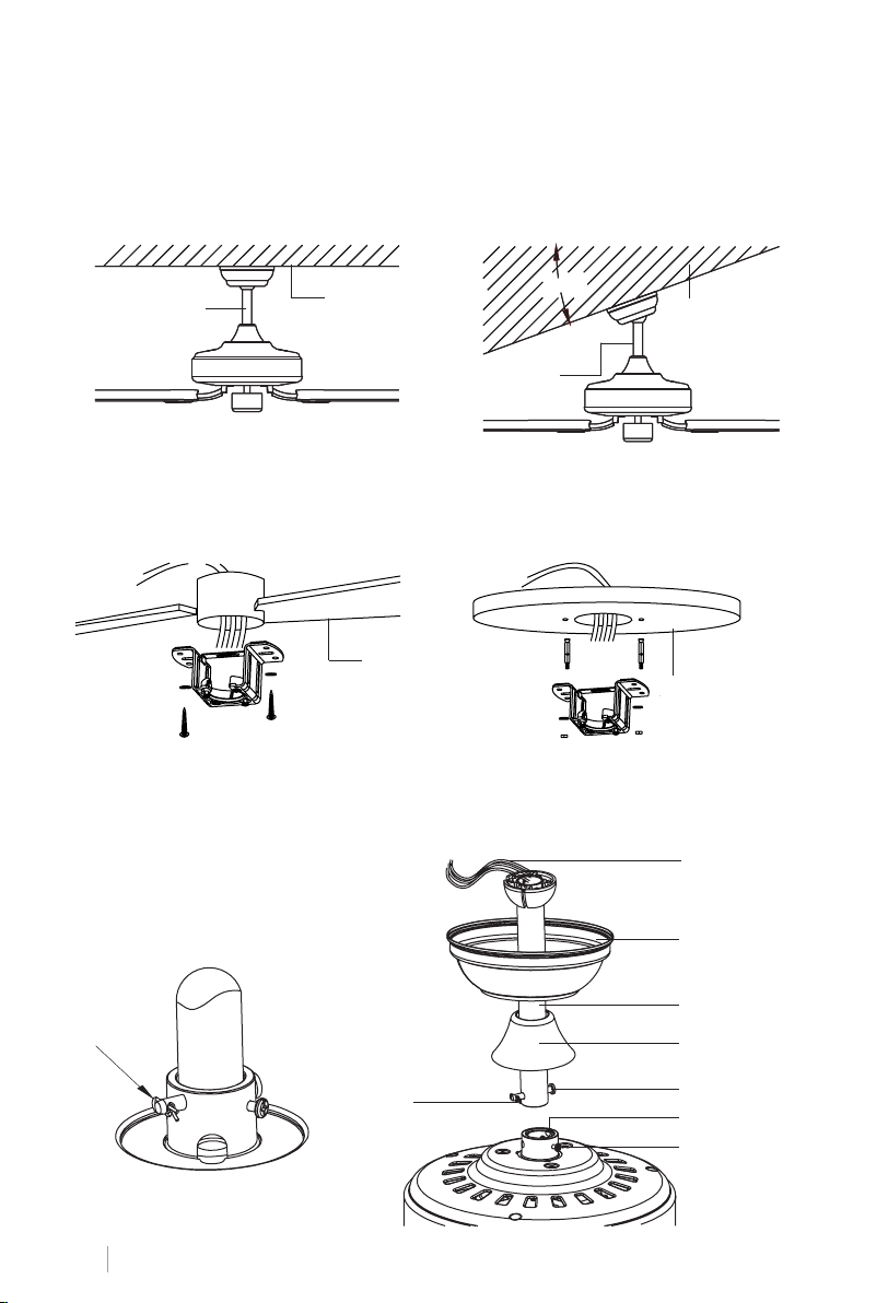
DE LOCATIE VAN DE VENTILATOR VOORBEREIDEN
Kies de ophangstang die het beste bij uw situatie past: deze heeft een ophangstang van 15
cm en een ophangstang van 25 cm.
Verwijder de bout van de stang door de pen te verwijderen en steek de vin (dakrand) en
motorroos door de ophangstang. Leid vervolgens de draden van de ventilatormotor in de
ophangbeugel. Monteer de draagstang op de motor en steek de bout en pen erin.
Traditionele
montagestijl
Ondersteuning
De traditionele beugel hangt met een
paal aan het plafond.
Hoekmontagestijl
Hoekmontage wordt aanbevolen op
schuine of gewelfde plafonds.
20°20°20°20°
Ondersteuning
MONTAGEBEUGEL INSTALLATIE
Houten dak
Betonnen
plafond
Boor een gat met een diameter van 8 mm in het betonnen plafond en breng een schroef aan.
Lijn vervolgens de beugel uit met het gat en zet hem vast met een moer.
MONTAGE EN OPHANGEN VAN DE VENTILATOR
Bekabeling
NEDERLANDS
50
Borgpen
Borgpen
Floron
Kogelkoppeling
Verfraaier
Dopschroef
Adapter
Bevestigingsschroef
Page 51
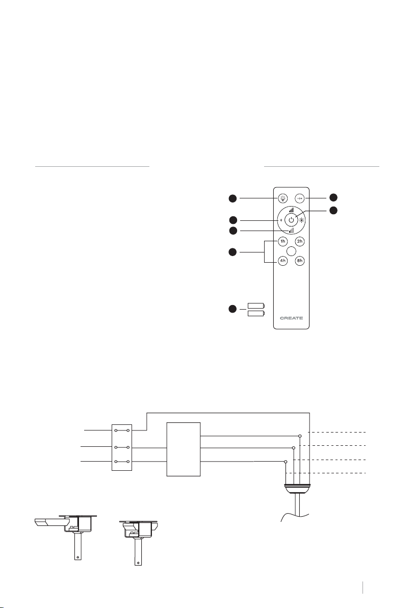
Advies: Wikkel wat elektrische tape om de draden om het gemakkelijker te maken om de
draden in de staaf te voeren. Dit zal je helpen ze bij elkaar te houden terwijl je ze in de stang
steekt.
• Draai de stelschroeven en de ring aan de bovenkant van het motorhuis los. Verwijder de
pinnen van de balk (als je dat nog niet hebt gedaan). Steek de rozet door de staaf.
• Leid de kabels door de balk en trek de overtollige kabels van de bovenkant van de balk om
ze strak te trekken.
• Plaats de staaf in de motorbehuizing en steek de pinnen die u eerder hebt verwijderd. Draai
de stelschroeven en ringen vast.
• Laat de rozet op het motorhuis zakken.
AFSTANDSBEDIENING
1. **Licht
2. **Lichtintensiteitscontrole
3. Regeling van de intensiteit van de
ventilator
1
2
3
6
7
4. Timer
5. Batterijen (2 x AAA)
4
6. **Kleurtemperatuurregeling
7. Aan / uit knop
** Functie alleen beschikbaar met LED-
5
kaart geïnstalleerd.
AFSTANDSBEDIENING VERBINDING
Maak de verbinding tussen de ontvangerkabels en de ventilatormotorkabels volgens de
kleuraanduidingen. Zorg ervoor dat de verbinding goed vastzit.
Aarding
AC
ger
Licht L
Ventilator L
Neutraal N
Invoer
Afstands-
L
N
L
Invoer N
bediening
ontvan-
Aarding
Licht L
Motor L
Neutraal N
Plaatsing van de afstandsbediening:
NEDERLANDS
51
Page 52
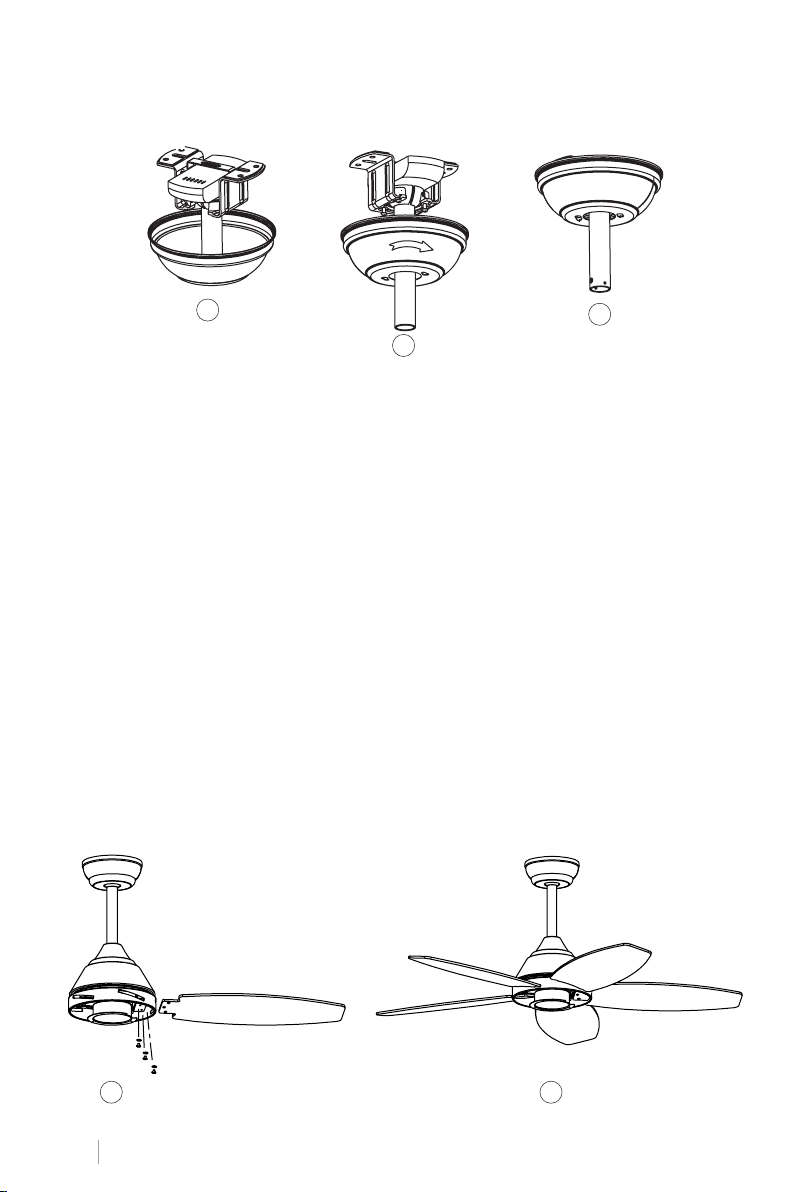
MONTAGE VAN DE ROZET
1
3
2
• Breng de rozet omhoog tot aan de montagebeugel en lijn de losgedraaide schroeven in de
montagebeugel uit met de gaten in de rozet.
• Draai de vin om aan te passen. Plaats de schroeven terug en zet ze vast met een schroevendraaier.
• Nadat u de montagebeugel aan de aansluitdoos heeft bevestigd, kunt u doorgaan met het
ophangen van de ventilator.
• Houd de ventilator stevig met beide handen vast. Steek de stang door de opening in de
montagebeugel en laat de kogel op de montagebeugel rusten.
• Draai de kogelkoppeling totdat deze is uitgelijnd met het lipje op de montagebeugel.
Advies: Een andere persoon moet je helpen de ladder vast te houden en je de ventilator overhandigen zodra je de ladder hebt beklommen.
DE MESSEN IN ELKAAR ZETTEN
Lijn de gaten in de meshouder uit met de gaten in de messen en het motorhuis en schroef
ze op hun plaats, maar draai de schroeven pas vast als ze allemaal op hun plaats zitten en
vastgeschroefd zijn.
Advies: Om tijd te besparen, kunt u de ringen op elke bout plaatsen voordat u de messen
installeert.
1 2
NEDERLANDS
52
Page 53
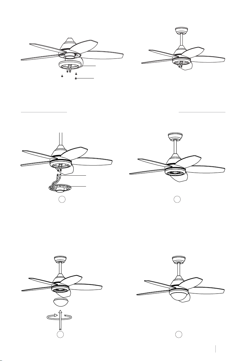
MONTAGE VAN HET PATCHPANEEL
Lamp paneel
Paneelschroef
Haak de plaat aan de onderkant van de ventilator door de schroefkoppen in de daarvoor
bestemde gaten te steken. Draai de schroeven vast en zet ze vast.
PLAFONDVENTILATOR MET LED-LICHT
MONTAGE VAN HET LED PANEEL EN HET DECORATIEVE SCHERM
Stekker met
enkele pen
LED
1 2
Verbind de enkele pinstekkers op de backplane met die op het LED-paneel. Het LED-paneel
is gemagnetiseerd, zodat het eenvoudig aan de backplane wordt bevestigd door de twee
delen samen te voegen.
Notitie: Pas op dat u de isolerende lipjes niet aanraakt tijdens het installeren of verwijderen
van de LED-kaart. Draai de schroeven niet te strak aan en draai ze niet snel vast, aangezien
dit de isolatielipjes kan beschadigen.
Plaats het decoratieve scherm op het LED-bord.
3 4
NEDERLANDS
53
Page 54
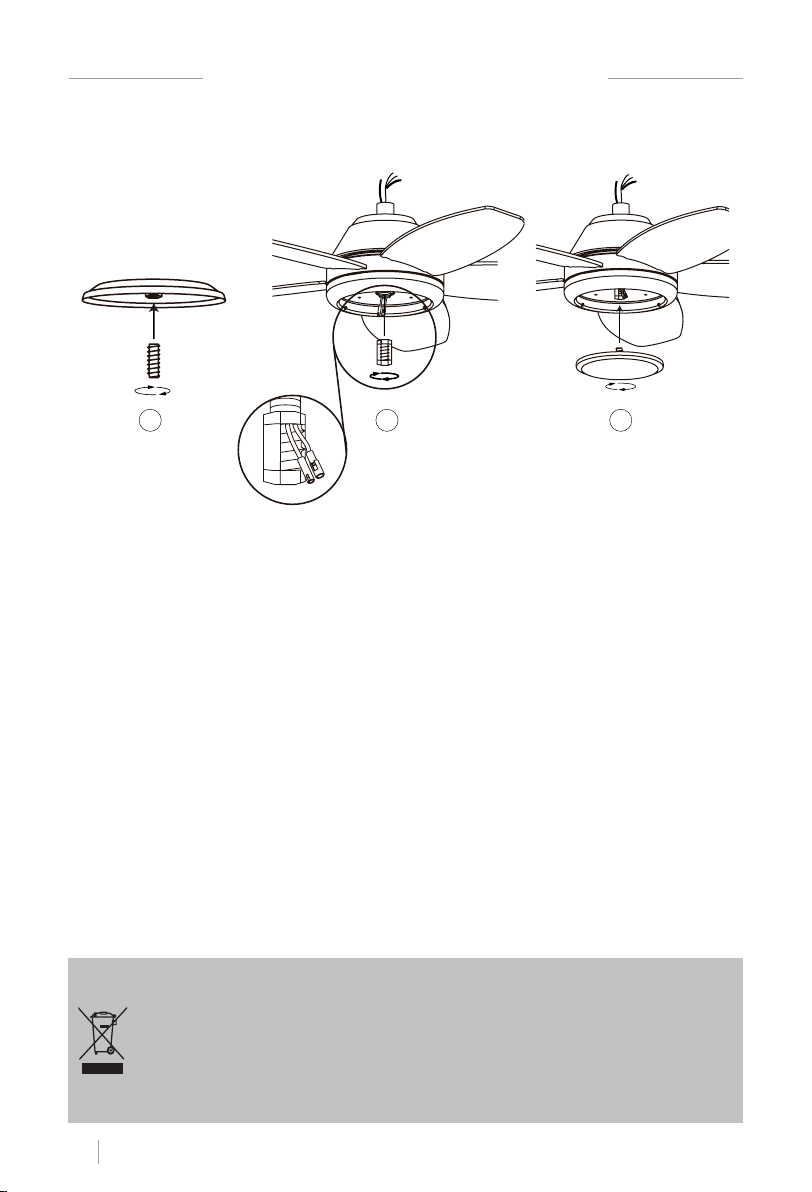
PLAFONDVENTILATOR ZONDER LED-LICHT
DE DECORATIEVE HOES MONTEREN
1 2 3
Nadat de aansluitplaat is gemonteerd en vastgezet, schroeft u de decoratieve afdekking met
de middelste schroef weer op de aansluitplaat.
CONTROLEER DE INSTALLATIE
• Controleer de juiste werking van de plafondventilator en controleer of er geen vreemde
beweging of verkeerde uitlijning wordt waargenomen in enig deel van de ventilator.
• In het geval dat enige vorm van brom / trilling te zien is, kunt u doorgaan met het afstellen
van de messen met de balanceerkit.
• In deze kit heb je zelfklevende gewichten en U-vormige clips.
• Zet de plafondventilator uit.
• Je kunt de paperclip in het midden van elk mes plaatsen en controleren of de trilling afneemt.
• Zet de ventilator aan en controleer. Als er geen verandering is, zet dan de ventilator uit en
voeg nog een clip toe aan een ander mes of gebruik de zelfklevende gewichten.
Volgens de Europese richtlijnen 2012/19 / EU en 2015/863 / EU, met betrekking tot de vermindering van het gebruik van
gevaarlijke stoffen in elektrische apparaten, naast de verwijdering van afval. Het doorgekruiste symbool op de container op de
verpakking geeft de verplichting aan dat het product aan het einde van zijn nuttige levensduur op een andere plaats dan ander
afval moet worden afgevoerd. Daarom moet de gebruiker het apparaat, wanneer het niet langer wordt gebruikt, aeveren bij het
juiste gedifferentieerde inzamelingscentrum voor elektronisch en elektrotechnisch afval, of het terugbrengen naar de verkoper
op het moment van aankoop van een nieuw apparaat van een gelijkwaardig type, een apparaat of een wijziging. van andere.
De gepaste gedifferentieerde inzameling van het ongebruikte apparaat voor de opeenvolgende milieuvriendelijke recycling-,
verwerkings- en verwijderingsprocessen draagt bij tot het vermijden van mogelijke negatieve effecten op het milieu en de
gezondheid, en bevordert de recycling van de materialen waaruit het apparaat bestaat. De onrechtmatige verwijdering van het
product door de gebruiker impliceert de toepassing van de wettelijke sancties.
NEDERLANDS
54
Page 55
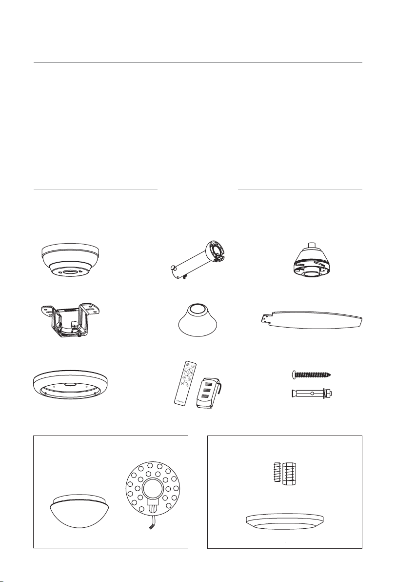
POLSKI
Dziękujemy za wybranie naszego wentylatora sutowego. Przed rozpoczęciem korzystania
z tego urządzenia i aby zapewnić jego najlepsze wykorzystanie, należy uważnie przeczytać
instrukcję.
Wymienione tutaj środki bezpieczeństwa zmniejszają ryzyko pożaru, porażenia prądem
elektrycznym i obrażeń, jeśli są właściwie przestrzegane. Instrukcję należy przechowywać
w bezpiecznym miejscu do wykorzystania w przyszłości, jak również gwarancję, dowód zakupu i opakowanie. Jeśli ma to zastosowanie, należy przekazać tę instrukcję przyszłemu
właścicielowi urządzenia. Podczas korzystania z urządzenia elektrycznego należy zawsze
przestrzegać podstawowych instrukcji bezpieczeństwa i środków zapobiegania ryzyku. Producent nie ponosi odpowiedzialności za szkody wynikające z nieprzestrzegania niniejszej
instrukcji przez użytkownika.
WYKAZ CZĘŚCI
Ostrożnie otwórz opakowanie i wyjmij części, które są w środku. Umieść je na podłodze na
dywanie lub kawałku plastiku wystarczająco dużym, aby uniknąć uszkodzeń. Sprawdź, czy
elementy wymienione poniżej znajdują się wewnątrz opakowania.
Floron Drążek zawieszenia z kulką
Uchwyt montażowy Ozdoba
Panel krosowy
Opcja ze światłem:
Panel LEDDekoracyjny ekran
Zdalne sterowanie Kołki rozporowe
Silnik
Ostrza
Opcja bez światła:
Bevestigingsschroeven
Dekoracyjna okładka
POLSKI
55
Page 56
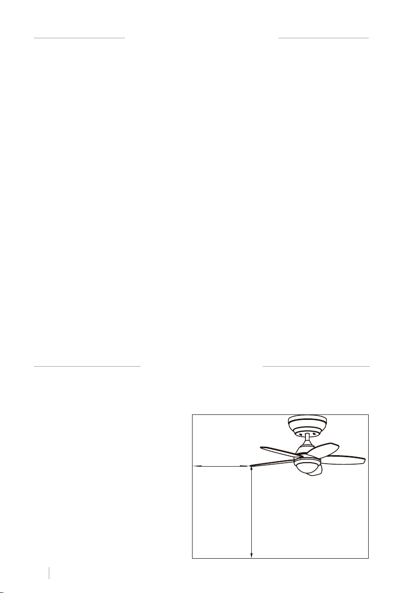
INSTRUKCJE BEZPIECZEŃSTWA
Podczas korzystania z dowolnego urządzenia elektrycznego należy zawsze przestrzegać następujących podstawowych środków ostrożności.
• Prosimy o uważne przeczytanie niniejszej instrukcji przed rozpoczęciem instalacji. Zacho-
waj te instrukcje.
• Aby zmniejszyć ryzyko obrażeń ciała, należy przymocować wentylator bezpośrednio do
konstrukcji nośnej budynku zgodnie z niniejszymi instrukcjami i używać wyłącznie dostarczonego materiału.
• Aby uniknąć możliwego porażenia prądem, przed zainstalowaniem wentylatora odłącz zasilanie, wyłączając przełączniki zasilania w panelu elektrycznym i powiązane przełączniki
ścienne. Jeśli nie można wyłączyć przełączników zasilania, użyj urządzenia ostrzegawcze-
go, takiego jak etykieta na panelu elektrycznym.
• Wszystkie kable muszą spełniać specykacje określone przez lokalne i krajowe przepisy
elektryczne oraz ANSI / NFPA 70. Jeśli nie jesteś zaznajomiony z instalacjami elektrycznymi, skonsultuj się z wykwalikowanym elektrykiem.
• Nie zginaj systemu mocowania ostrzy podczas montażu, przechylania lub czyszczenia ostrzy.
• Nie wkładaj innych przedmiotów między łopatki wentylatora.
• Aby zmniejszyć ryzyko pożaru, porażenia prądem lub uszkodzenia silnika, nie używaj pół-
przewodnikowego regulatora prędkości z tym wentylatorem. Używaj tylko oryginalnych
regulatorów prędkości.
• To urządzenie może być używane przez dzieci w wieku 8 lat i starsze oraz osoby o ograniczonych zdolnościach zycznych, sensorycznych lub umysłowych, lub z brakiem doświadczenia lub ograniczoną wiedzą, pod warunkiem, że są one nadzorowane przez osobę odpowiedzialną za ich bezpieczeństwo lub która została przeszkolona w obsłudze urządzenie
bezpiecznie. Dzieci nie mogą bawić się tym urządzeniem. Nie powinni też czyścić i konserwować urządzenia, chyba że mają ponad 8 lat i są pod nadzorem. Dzieci muszą być pod
ścisłym nadzorem podczas korzystania z jakiegokolwiek urządzenia.
UWAGA: Instrukcje i środki ostrożności zawarte w tej instrukcji mogą nie obejmować wszystkich możliwych problemów i sytuacji. Musisz zrozumieć, że zarówno zdrowy rozsądek, jak i
ostrożność są niezbędne podczas instalacji i użytkowania wentylatora.
INSTRUKCJE INSTALACJI
• Zaznacz prawidłowe położenie otworów i zamocuj wspornik sutowy za pomocą metalowych śrub kotwowych lub śrub i podkładek odpowiednich dla wybranego rodzaju sutu.
• Przed zawieszeniem wentylatora należy sprawdzić poprawność montażu wspornika. Płyta
ta musi wytrzymać cały ciężar wentylatora.
PRZYGOTOWANIE DO INSTALACJI
• Aby uniknąć obrażeń ciała i obrażeń
ciała, należy upewnić się, że miejsce,
w którym ma być zawieszony wentylator, umożliwia ustawienie łopatek
w odległości równej lub większej niż
2,3 m od ziemi i 76 cm od najbliższej
ściany lub przeszkody.
• Upewnij się, że skrzynka przyłącze-
niowa jest odpowiednio przymoco-
wana do konstrukcji budynku i może
wytrzymać cały ciężar wentylatora.
POLSKI
56
76 cm od
najbliższej
ściany lub
przeszkody
2,3 m od
ostrzy do
podłoża
Page 57
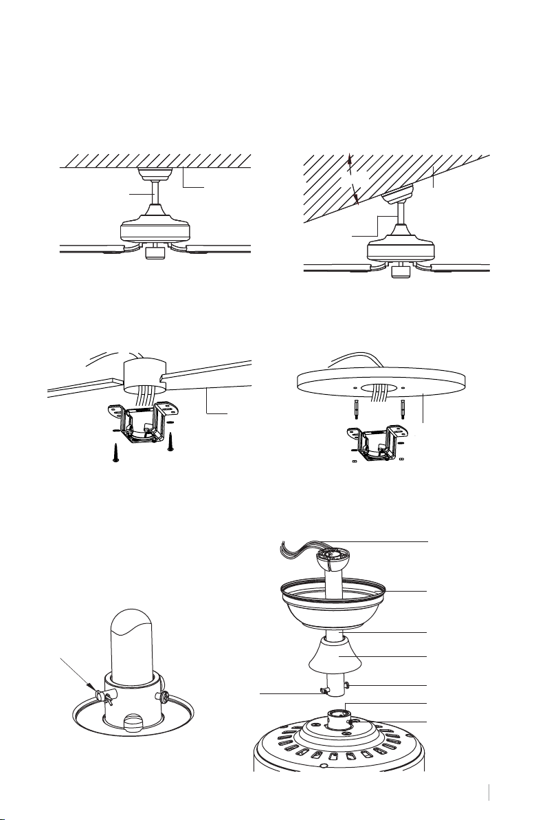
PRZYGOTOWANIE LOKALIZACJI WENTYLATORA
Wybierz belkę do zawieszenia, która najlepiej pasuje do Twojej sytuacji: ma drążek do zawieszania 15 cm i 25 cm.
Odkręć śrubę z pręta, wyjmując sworzeń i przeprowadź płetwę (wykończenie dachu) i silnik podniesiony przez pręt wieszaka. Następnie poprowadź przewody silnika wentylatora
wewnątrz pręta wieszaka. Przymocuj wieszak do silnika i włóż śrubę i kołek.
Tradycyjny styl
montażu
Wsparcie
Tradycyjny uchwyt zwisa z sutu za pomocą słupa.
Styl mocowania
kątowego
Montaż pod kątem jest zalecany na stropach skośnych lub sklepionych.
20°20°20°20°
Wsparcie
MONTAŻ WSPORNIKA MONTAŻOWEGO
Dach drewniany
Strop betonowy
Wywierć otwór o średnicy 8 mm w betonowym sucie i włóż śrubę. Następnie dopasuj
wspornik do otworu i zabezpiecz go nakrętką.
MONTAŻ I ZAWIESZANIE WENTYLATORA
Okablowanie
Sworzeń blokujący
Sworzeń
blokujący
Floron
Zaczep kulowy
Ozdoba
Śruba mocująca
Adapter
Śruba mocująca
POLSKI
57
Page 58
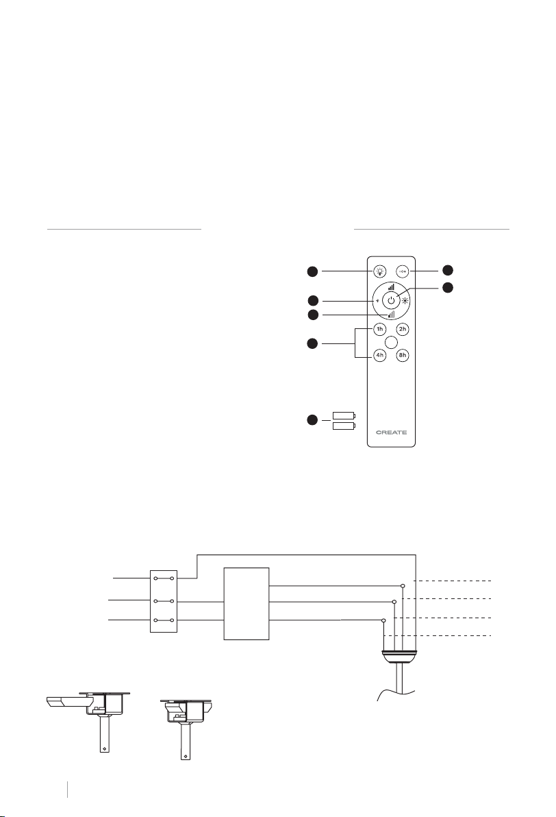
Rada: Aby ułatwić wprowadzanie przewodów do pręta, owiń je taśmą izolacyjną. Pomoże ci
to utrzymać je razem podczas wkładania ich do paska.
• Poluzuj wkręty ustalające i podkładkę na górze obudowy silnika. Usuń szpilki z paska (jeśli
jeszcze tego nie zrobiłeś). Przełóż rozetę przez pręt.
• Przełóż kable przez pręt i pociągnij nadmiar kabli od góry pręta, aby je dokręcić.
• Umieść pręt wewnątrz obudowy silnika i włóż wyjęte wcześniej kołki. Dokręcić śruby doci-
skowe i podkładki.
• Opuść rozetę na obudowę silnika.
ZDALNE STEROWANIE
1. **Światło
2. **Kontrola natężenia światła
3. Kontrola intensywności wentylatora
4. Regulator czasowy
5. Baterie (2 x AAA)
6. **Regulacja temperatury barwowej
1
2
3
4
6
7
7. Włącznik / wyłącznik
** Funkcja dostępna tylko przy zainstalowanej płycie LED.
5
POŁĄCZENIE ZDALNEGO STEROWANIA
Wykonaj połączenie między przewodami odbiornika i przewodami silnika wentylatora zgodnie z oznaczeniami kolorów. Upewnij się, że połączenie jest szczelne.
AC
Grunt
pilota
Światło L
Wentylator L
Neutralny N
Wejście
Odbiornik
L
N
L
Wejście
N
Grunt
Światło L
Silnik L
Neutralny N
Umieszczenie pilota:
POLSKI
58
Page 59
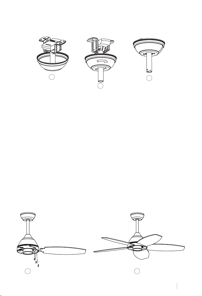
MONTAŻ ROZETY
1
3
2
• Podnieś rozetę do wspornika montażowego i wyrównaj poluzowane śruby wspornika montażowego z otworami w rozecie.
• Obróć płetwę, aby wyregulować. Ponownie włóż śruby i zamocuj je śrubokrętem.
• Po przymocowaniu wspornika montażowego do skrzynki przyłączeniowej można przystą-
pić do zawieszenia wentylatora.
• Mocno trzymaj wentylator obiema rękami. Przełóż pręt przez otwór we wsporniku montażowym i pozwól kuli spocząć na wsporniku montażowym.
• Obróć zaczep kulowy, aż zrówna się z wypustką na wsporniku montażowym.
Rada: Druga osoba powinna pomóc ci trzymać drabinę i wręczyć ci wentylator po wejściu na
drabinę.
MONTAŻ OSTRZY
Dopasuj otwory we wsporniku ostrza do otworów w ostrzach i korpusie silnika i przykręć je
na miejsce, ale nie dokręcaj śrub, dopóki wszystkie nie znajdą się na miejscu i nie zostaną
wkręcone.
Rada: Aby zaoszczędzić czas, przed zamontowaniem ostrzy można nałożyć podkładki na
każdą śrubę.
1 2
POLSKI
59
Page 60
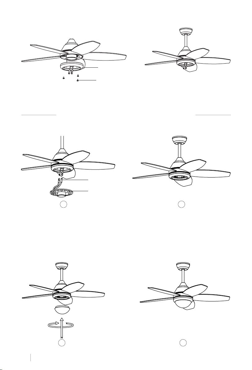
MONTAŻ PANELU KROSOWEGO
Panel lampy
Śruba panelu
Zawiesić płytę na spodzie wentylatora, wkładając łby śrub w wyznaczone otwory. Wkręć śruby, a następnie zabezpiecz je.
WENTYLATOR SUFITOWY Z OŚWIETLENIEM LED
MONTAŻ PANELU LED I EKRANU DEKORACYJNEGO
Wtyczka jednopinowa
LED
1 2
Połącz pojedyncze wtyczki na płycie montażowej z wtyczkami na panelu LED. Panel LED jest
namagnesowany, więc jest mocowany do płyty montażowej po prostu przez złożenie dwóch
części razem.
Uwaga: Podczas instalowania lub wyjmowania płyty wskaźników LED należy uważać, aby
nie dotknąć zakładek izolacyjnych. Nie dokręcaj śrub zbyt mocno ani nie wkręcaj ich zbyt
szybko, ponieważ może to spowodować uszkodzenie zakładek izolacyjnych.
Umieść dekoracyjny ekran na płycie LED.
3 4
POLSKI
60
Page 61
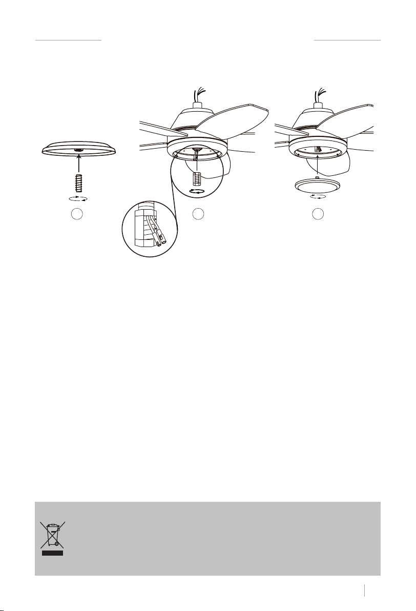
WENTYLATOR SUFITOWY BEZ ŚWIATŁA LED
MONTAŻ OZDOBNEJ OSŁONY
1 2 3
Po zamontowaniu i zabezpieczeniu płytki przyłączeniowej przykręcić pokrywę dekoracyjną z
powrotem do płytki łączącej za pomocą środkowej śruby.
SPRAWDŹ INSTALACJĘ
• Sprawdź poprawność działania wentylatora sutowego, sprawdzając, czy nie zaobserwowano dziwnych ruchów lub niewspółosiowości w żadnej części wentylatora.
• W przypadku zauważenia jakiegokolwiek przydźwięku / wibracji, można przystąpić do regulacji ostrzy za pomocą zestawu wyważającego.
• W tym zestawie masz samoprzylepne ciężarki i klipsy w kształcie litery U.
• Wyłącz wentylator sutowy.
• Możesz umieścić spinacz w środku dowolnego ostrza i sprawdzić, czy wibracje spadną.
• Włącz wentylator i sprawdź. Jeśli nie ma zmian, wyłącz wentylator i dodaj kolejny klips do
innego ostrza lub użyj ciężarków samoprzylepnych.
Zgodnie z wytycznymi europejskimi 2012/19 / UE i 2015/863 / UE, odnoszące się do ograniczenia stosowania niebezpiecznych substancji w urządzeniach elektrycznych, oprócz usuwania odpadów. Przekreślony symbol na pojemniku znajdujący
się na opakowaniu oznacza obowiązek utylizacji produktu po zakończeniu jego okresu użytkowania w miejscu innym niż
inne odpady. W związku z tym użytkownik musi dostarczyć wyrób, gdy nie jest już używany, do odpowiedniego oddzielnego
punktu zbiórki odpadów elektronicznych i elektrotechnicznych lub zwrócić go sprzedawcy przy zakupie nowego urządzenia
równoważnego typu, jednego lub wymiany. innych. Odpowiednio zróżnicowana zbiórka nieużywanego urządzenia do kolejnych
przyjaznych dla środowiska procesów recyklingu, przetwarzania i unieszkodliwiania pomaga uniknąć możliwych negatywnych
skutków dla środowiska i zdrowia oraz sprzyja recyklingowi materiałów, z których składa się urządzenie. Nieuczciwe usuwanie
produktu przez użytkownika oznacza zastosowanie sankcji przewidzianych prawem.
POLSKI
61
Page 62

Page 63

Page 64

/ Made in P.R.C.
 Loading...