

Page 1
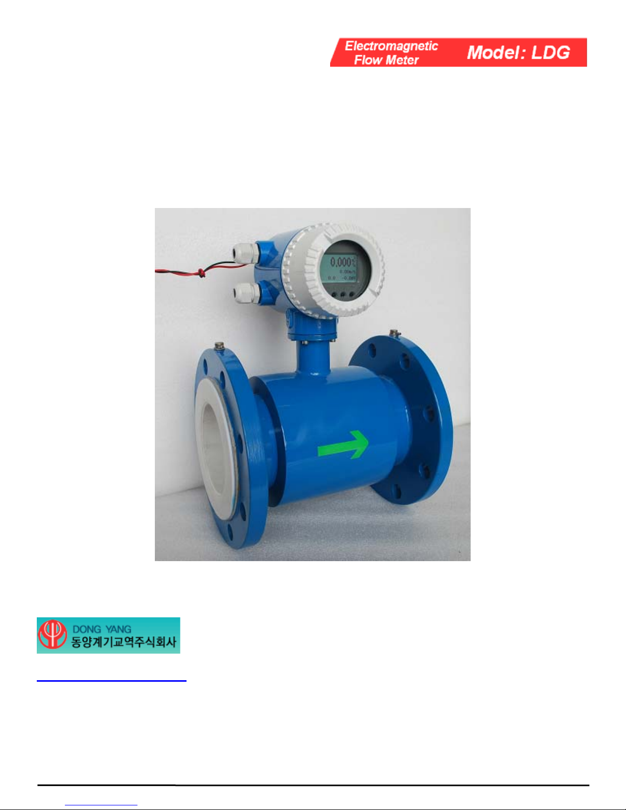
Electromagnetic Flow Meter
Owner’s Manual
http://flowmeternara.com/
Address: #910, KolonScienceValley2nd,
#811,Guro-dong,Guro-gu,Seoul,
Korea…………….
TEL: +82-2-2025-0562
FAX: +82-2-2025-0565
Manual No. 090820-4 Rev.A
Page 2

Content
1.0 GENERAL INFORMATION ...............................................................................................2
2.0 SPECIFICATIONS................................................................................................................4
3.0 MODEL AND SELECTION.................................................................................................5
4.0 CAUTIONS FOR INSTALLATION....................................................................................6
5.0 ELECTRICAL WIRING ......................................................................................................9
6.0 PROGRAMMING AND SETUP.......................................................................................... 9
7.0 TROUBLESHOOTING.......................................................................................................13
Copyright Reserved, DONGYANG Corporation 1
Page 3
1.0 GENERAL INFORMATION
This manual will assist you in installing, using and maintaining your DONGYANG flow meter.
It is your responsibility to make sure that all operators have access to adequate instructions
about safe operating and maintenance procedure.………………………………………………
Warning
For your safety, review the major warnings and cautions below before operating your
equipment.……………………………………………………………………………..
1. Use only fluids that are compatible with
the housing material and wetted components
of your meter.
2. When measuring flammable liquids,
observe precautions against fire or explosion.
3. When handling hazardous liquids, always
follow the fluids manufacturer’s safety
precautions.
4. When working in hazardous environments,
always exercise appropriate safety
precautions.
…………………………..
5. During meter removal, fluids may spill.
Follow the fluids manufacturer’s safety
precautions for clean up of minor spills.
…………………………..
6. When tightening the meter, use a
wrench only on the wrench flats. …………...
7. For best results, calibrate the meter at
least 1 time per year.……………………
Product Description
DONGYANG LDG electromagnetic flow meters are intended for fluid measurement in most
industries including water, wastewater, food and beverage, pharmaceutical and chemical.
……….
There are two basic components of DONGYANG electromagnetic flow meter: 1)The Detector,
which includes the flow tube, isolating liner and measuring electrodes, and 2) The Converter,
which is the electronic device responsible for signal processing, flow calculation, display and
output signals.
The materials of construction of the wetted parts (liner and electrodes) should be appropriate for
the specifications on the intended type of service. Review of the compatibilities consistent with
the specifications is recommended.
All DONGYANG’s electromagnetic flow meters are factory tested and calibrated. A calibration
certificate is included in the shipment of each meter.
Copyright Reserved, DONGYANG Corporation 2
Page 4
Unpacking and Inspection
Upon receipt, examine your meter for visible damage. The meter is a precision measuring
instrument and should be handled carefully. Remove the protective plugs and caps for a
thorough inspection. If any items are damaged or missing, contact DONGYANG.
Make sure the flow meter model meets your specific needs. For your future reference, it might
be useful to record this information on nameplate in the manual in case it becomes unreadable
on the meter.
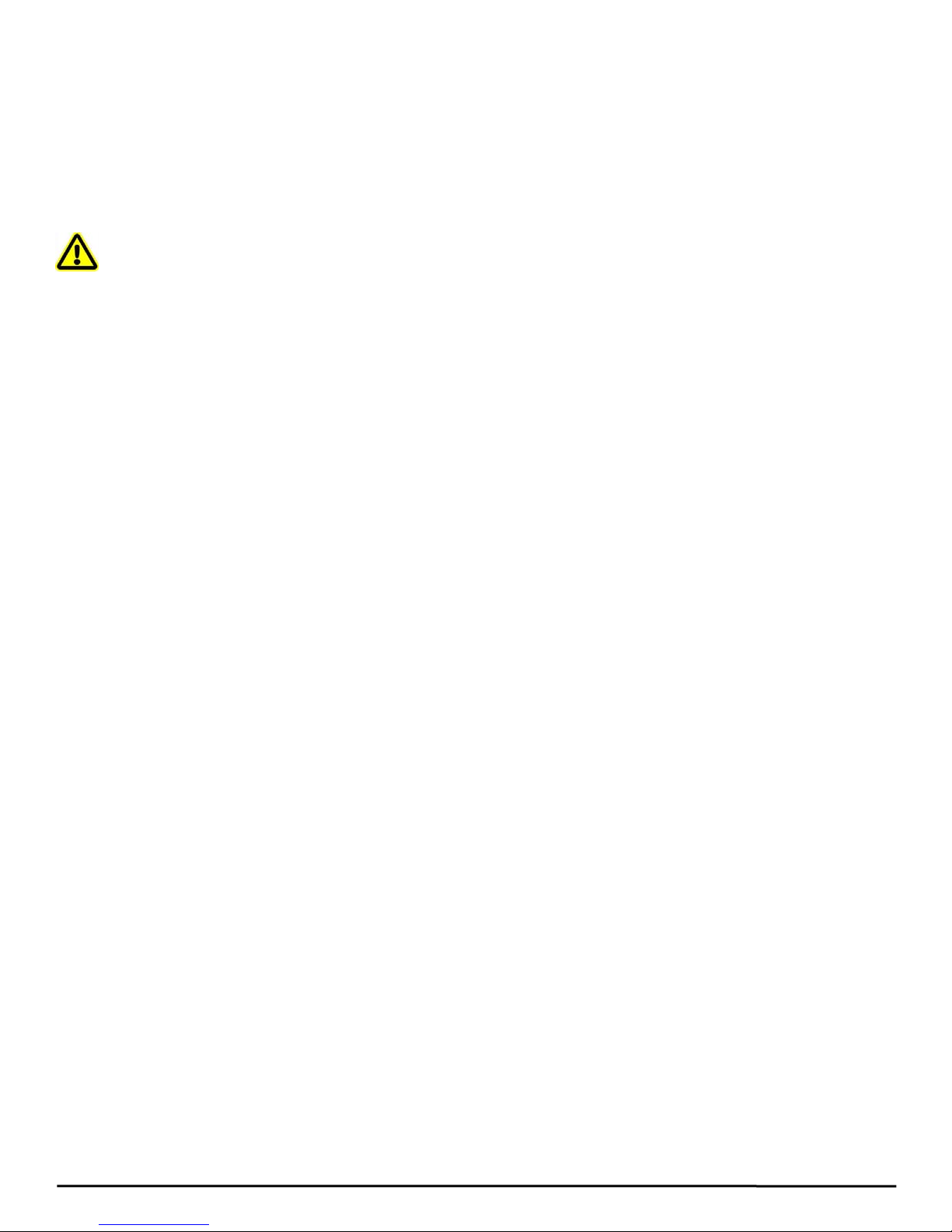
Transportation and Handling
Do not lift the detector from the Converter
housing, the junction box or the connecting
cable. Use lifting lugs for larger sizes is
recommended. Very large meter sizes are
packed and crated with the meter laying on
its side for shipping safety and stability
reasons. In order to lift the meter in vertical
position, it's recommended to use a sling
rigged method as shown below.
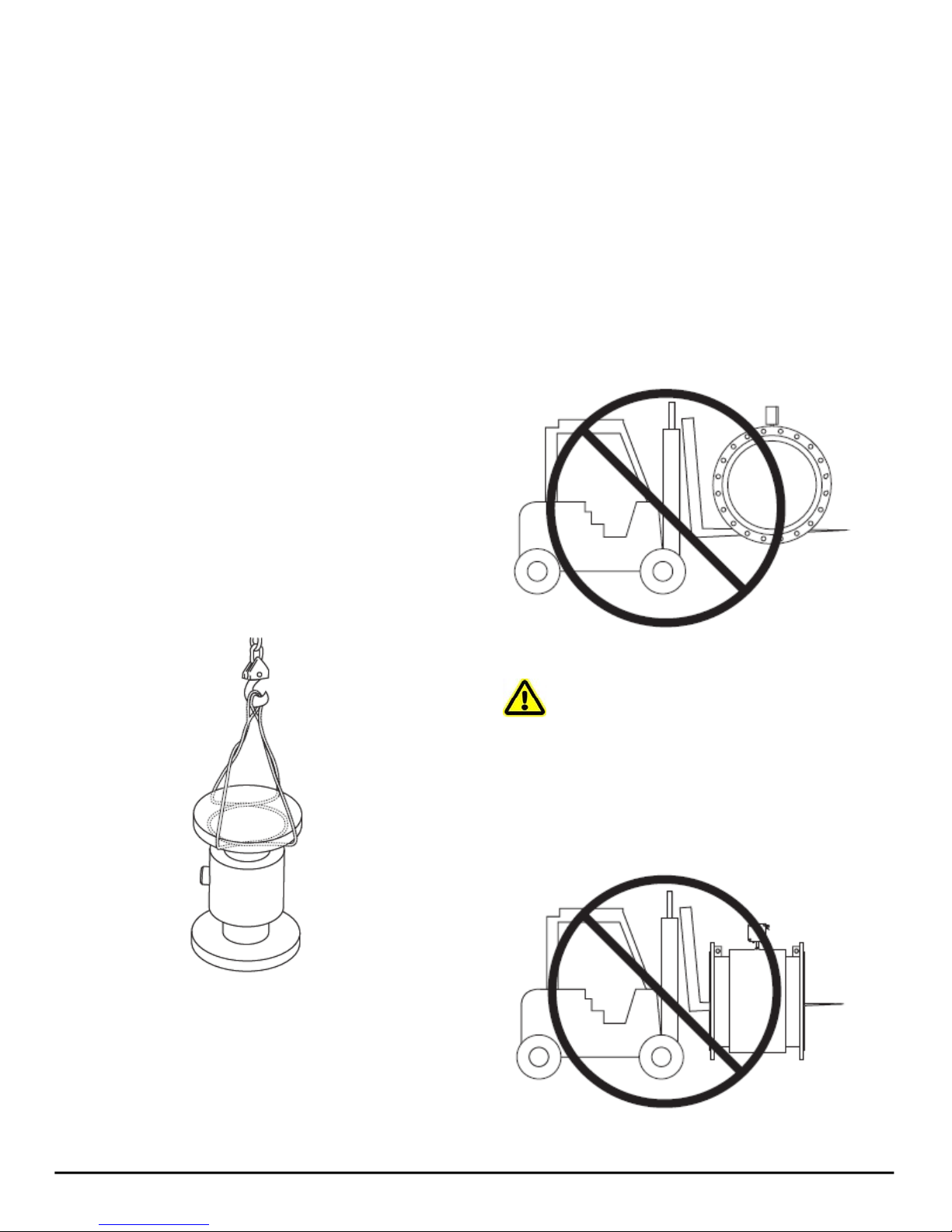
If using a forklift, do not lift the detector
from its body between the flanges. The
housing could be accidentally dented and
permanent damage could be caused to the
internal coil assemblies.
Warning: NEVER introduce the
forklift, chains, wire slings or any other
sharp object inside the flow tube for lifting
or handling purpose. This could permanently
damage the isolating liner and could render
the meter inoperable.
Copyright Reserved, DONGYANG Corporation 3
Page 5

2.0 SPECIFICATIONS
Converter:
Power Supply: 85-265Vac (Optional: 18-36
Vdc)
Power Consumption: 10W
Accuracy:
± 0.5% accuracy of rate from 0.5-10 m/s
± 1.0% accuracy of rate from 0.1-0.5 m/s
Repeatability: 0.2%
Minimum Fluid Conductivity:
5.0 micromhos/cm
Flow Direction: Unidirectional or
bidirectional, 2 separate totalizers
(programmable)
Analog Outputs: 4-20mA, 500ohms Max
Load
Output Frequency: Scaled Pulse output,
(open collector) Max 5Khz
Noise Damping: Programmable
Pulse Width: Programmable up to 500ms
Zero-point Stability: Automatic correction
Housing: Cast aluminum, powder coated
paint
Mounting: Integral mount or remote mount
Ambient Temperature: -4 to 140° F (-20 to
60° C)
Detector:
Flow Range: 0.03-10 m/s
Sizes: 10 to 2200 mm
Min. Conductivity: 5 micromhos/cm
Accuracy:
± 0.5% accuracy of rate from 0.5-10 m/s
± 1.0% accuracy of rate from 0.1-0.5 m/s
Electrode Materials:
Standard: 316 Stainless Steel
Optional: Tantalum
Liner Material: PTFE, FEP (Rubber)
Fluid Temperature:
PTFE: 100°C Standard (Customized: 180°C)
FEP: 60°C
Pressure Limits:
1.0 Mpa; Optional 1.6; 2.5; 4.0 Mpa
Coil Power: Pulsed DC
Ambient Temperature: -20°C to 60°C
Pipe Spool Material: 316 Stainless Steel
Meter Housing Material:
Carbon Steel welded
Flanges:
Carbon Steel - Standard (ISO 7005-1)
316 Stainless Steel - Optional
Optional Stainless Steel Grounding Rings
Measurable Flow Rate Range:
Note: The flow range as blow is for recommended use. Consult the factory if you have special
requirement.
Diameter (mm) 10 15 20 25 32 40 50 65
Qmin (m3/h) 0.08 0.34 0.34 0.53 0.87 1.35 2.1 3.5
Qmax (m3/h) 2 8 8 12 20 32 49 84
Diameter (mm) 80 100 125 150 200 250 300 350
Qmin (m3/h) 5.4 8.5 13 19 34 53 76 104
Qmax (m3/h) 127 197 310 445 791 1236 1780 2423
Diameter (mm) 400 450 500 550 600 700 800 900
Qmin (m3/h) 136 191 212 263 305 415 543 760
Qmax (m3/h) 3165 4294 4945 6322 7122 9693 12660 17634
Copyright Reserved, DONGYANG Corporation 4
Page 6

3.0 MODEL AND SELECTION
Model Selection (See Table 1)
Table 1. Model Selection Guidance
Model Suffix Code
LDG-
□ /□ /□ /□ /□ /□ /□ /□ /□
Description
Diameter
combination
Electrode
Material
Signal Output
Liner material
Display Unit
10-2200mm
S Integrated type
L
Remote type
M Stainless steel 316
T Ti
D Ta
H Hastelloy alloy
P Pt
N
Ni
0 No output
1
4-20mA/1-5KHz
X FEP
F
PTFE
0 No display unit
1
Display unit
Communication
Grounding Ring
Maximum Flow
Copyright Reserved, DONGYANG Corporation 5
0 No communication
1 RS485
2
MODBUS
0 No grounding ring
1
Grounding ring
Maximum flow
(n)
(measuring range) m
3
/h
Page 7

4.0 CAUTIONS FOR INSTALLATION
Mounting Positions
• Pipes must be fully filled with liquids. It
is essential that pipes remain fully filled
at all times, otherwise flow rate
indications may be affected and
measurement errors may be caused.
• Avoid Air Bubbles. If air bubbles enter
a measurement pipe, flow rate
indications may be affected and
measurement errors may be caused.
• Avoid all pipe locations where the flow
is pulsating, such as in the outlet side of
piston or diaphragm pumps.
• Avoid locations near equipment
producing electrical interference such as
electric motors, transformers, variable
frequency, etc.
• Install the meter with enough room for
future access for maintenance purposes.
• The mag meter isolating liner, whether
if it is PTFE or Rubber, is not intended
to be used as gasket material. Standard
gaskets (not provided) should be
installed to ensure a proper hydraulic
seal. When installing the gaskets, make
sure they are properly centered to avoid
flow restriction or turbulence. Do not
use graphite or any electrically
conductive sealing compound to hold
the gaskets in place during installation.
This could affect the reading accuracy
of the measuring signal.
Warning: Precaution for direct sunshine and rain when the meter is installed outside.
Required Lengths of Straight Runs
For optimum accuracy performance, it is required to provide sufficient inlet and outlet straight
pipe runs. An equivalent to 3 diameters of straight pipe is required on the inlet side, and 2
diameters on the outlet side. There are no special requirements for standard concentric pipe
reducers. See diagram1 for required straight runs when there is altering device.
Diagram 1. Required straight runs
Copyright Reserved, DONGYANG Corporation 6
Page 8

Special Notice
♦ When the meter contains removable coverplates. Leave the coverplate installed unless
accessory modules specify removal. Don’t remove the coverplates when the meter is
powered, or electrical shock and explosion hazard can be caused.
Flange Connections
The flange follows GB/T 9119-2000 (ISO 7005-1) RF (Raised Face).
Note: flange can be customized following other criterias.
Use a gasket between the meter flange and mating flange. Determine the material of the gasket
based on the operating conditions and type of fluid.………………………………………….
Note: Do not over tighten the flange bolts. This may cause the gasket to be compressed into the
flow stream and may decrease the accuracy of the meter.
Installation Dimensions
See Figure 1 and Table 2 for detailed dimensions.
Figure 1: Drawings for Integrated/Remote Electromagnetic Flow Meter
Copyright Reserved, DONGYANG Corporation 7
Page 9

Table 2. Dimensions (Unit: mm)
Diameter DN a D Do n × Φ A
10 230 90 60 4 × 14
15 230 95 65 4 × 14
20 230 105 75 4 × 14
25 230 115 85 4 × 14
32 230 140 100 4 × 18
40 230 150 110 4 × 18
50 230 165 125 4 × 18
65 230 185 145 8 × 18
80 230 200 160 8 × 18
100 230 220 180 8 × 18
125 280 245 210 8 × 18
150 280 285 240 8 × 22
200 310 340 295 12 × 22
250 360 405 355 12 × 22
300 460 460 410 12 × 22
350 460 520 470 16 × 22
400 460 580 525 16 × 26
450 460 640 585 20 × 26
500 600 715 650 20 × 26
600 600 840 770 20 × 30
700 700 895 840 24 × 33
800 800 1015 950 24 × 33
900 900 1110 1050 28 × 33
1000 1000 1230 1160 28 × 36
1200 1200 1405 1340 32 × 33
1400 1400 1630 1560 36 × 36
1600 1600 1830 1760 40 × 36
1800 1800 2045 1970 44 × 39
2000 2000 2265 2180 48 × 42
2200 2200 2405 2315 52 × 45
Copyright Reserved, DONGYANG Corporation 8
Page 10

5.0 ELECTRICAL WIRING
Warning: Electrical Hazard
Disconnect power before beginning installation.
Terminal Configuration
Electrical
L/+
Shock Hazard
N/-
I+
I -
F+
F -
Terminal Wiring
Warning: The mag flow meter is powered by EITHER 220Vac OR 24V DC. Please use
right power supply or maybe cause permanent damage on meter.
6.0 PROGRAMMING AND SETUP
The display panel comes preprogrammed from the factory and in most instances will not require
any additional manipulation. However, if you will be using the flow signal outputs or need to
reprogram the meter to suit your particular needs, it will be necessary to familiarize yourself
with the programming procedures.
Figure 2. Enter Parameter and Display Panel Illustration
Copyright Reserved, DONGYANG Corporation 9
Page 11

Figure 3. Detailed Illustration for Menu - Basic
Copyright Reserved, DONGYANG Corporation 10
Page 12

Figure 4. Detailed Illustration for Menu - System
Copyright Reserved, DONGYANG Corporation 11
Page 13

Figure 5. Detailed Illustration for Menu – Calibration
Notice: The Menu - Detail is only for factory programming, and it’s not permitted for user to
change these setting in Menu – Detail.
…………………………………...
Copyright Reserved, DONGYANG Corporation 12
Page 14

7.0 TROUBLESHOOTING
Symptom Probable Cause Solution
Measurement is not
accurate
Flow rate indication
is unstable
No Display
1. Parameter wrong
Check the parameters (Transmitter,
K-factor and size)
2. Pipe is not fully filled Check if meter is fully filled
Make sure meter is properly
1. Grounding issue
grounded to a good earth ground
Make sure fluid does not contain air
2. Air
bubbles
Make sure Converter is not too
3. Converter location – outside
close to sources of electrical
electrical interference
interference
1. No power Apply correct power
2. Incorrect power Check power value
Check power input/output
3. Wiring connections
connections
4. Fuse blown Replace fuse
Copyright Reserved, DONGYANG Corporation 13
Page 15

Limited Warranty Policy
DONGYANG hereby provides a limited warranty against defects in materials and
workmanship. This product includes a 1-year warranty. The warranty period shall begin on the
date of the original new equipment purchase. Warrantor’s obligation hereunder shall be limited
to repairing defective workmanship or replacing or repairing any defective parts.。。
In the event Purchaser believes the DONGYANG product is defective, the product must be
returned to DONGYANG, transportation prepaid by Purchaser, within the appropriate warranty
period relative to the product. If DONGYANG’s inspection determines the workmanship or
materials are defective and the required maintenance has been performed and, has been properly
installed and operated, the product will be either repaired or replaced, at DONGYANG’s sole
determination, free of additional charge, and the goods will be returned, transportation paid by
DONGYANG, using a transportation method selected by DONGYANG.…
Prior to returning the product to DONGYANG, Purchaser must obtain a Returned Material
Authorization (RMA) Number from DONGYANG’s Customer Service Department within 30
days after discovery of a purported breach of warranty, but not later than the warranty period;
otherwise, such claims shall be deemed waived.
If DONGYANG’s inspection reveals the DONGYANG product to be free of defects in material
and workmanship or such inspection reveals the goods were improperly used, improperly
installed, and/or improperly selected for service intended, DONGYANG will notify the
purchaser in writing and will deliver the goods back to Purchaser upon receipt of Purchaser's
written instructions and agreement to pay the cost of transportation. If Purchaser does not
respond within thirty (30) days after notice from DONGYANG, the goods will be disposed of in
DONGYANG’s discretion.
DONGYANG does not warrant the product to meet the requirements of any safety code or other
jurisdiction, and Purchaser assumes all risk and liability whatsoever resulting from the use
thereof, whether used singlely or in combination with other machines or apparatus.
This warranty shall not apply to any DONGYANG product or parts thereof, which have been
repaired outside DONGYANG’s factory or altered in any way, or have been subject to misuse,
negligence, or accident, or have not been operated in accordance with DONGYANG’s printed
instructions or have been operated under conditions more severe than, or otherwise exceeding,
FOR NON-WARRANTY REPAIRS OR CALIBRATIONS, consult DONGYANG for current
repair/calibration charges. Have the following information available BEFORE contacting
DONGYANG:
1. P.O. number to cover the COST of the repair/calibration,
2. Model and serial number of the product, and
3. Repair instructions and/or specific problems relative to the product.
Copyright Reserved, DONGYANG Corporation 14
 Loading...