

FLOWMAX Technologies FLOWMAX-120, FLOWMAX–90 Instruction Manual
Instruction Manual
for model
FLOWMAX-120
Condensing water heater
116,000 BTU
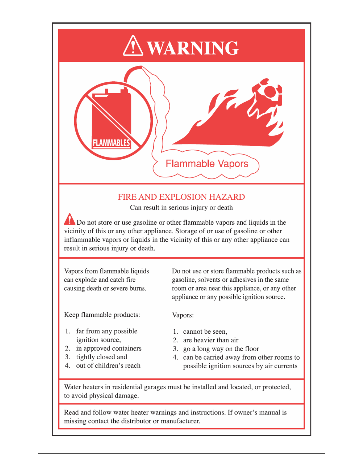
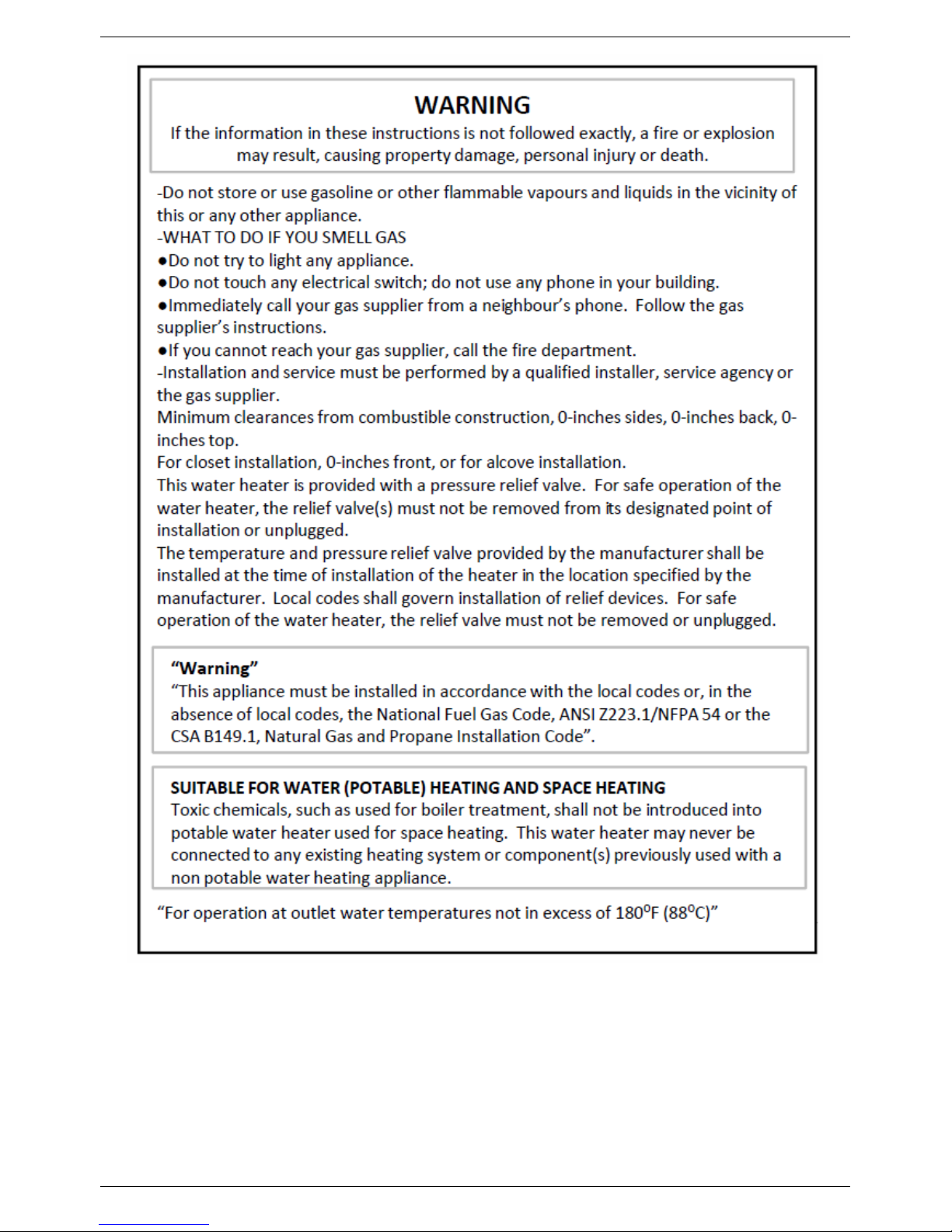
WARNING
If the information in these instructions is not followed exactly, a fire or explosion may result, causing property damage, personal injury or death.
-Do not store or use gasoline or other flammable vapours and liquids in the vicinity of this or any other appliance.
-WHAT TO DO IF YO U SMELL GAS
●Do not try to light any appliance.
●Do not touch any electrical switch; do not use any phone in your bu ilding.
●Immediately call your gas supplier from a neighb our’s phone. Follo w the gas supplier’s instructions.
●If you cannot reach your gas supplier, call the fire d epartment.
-Installation and service must be performed by a qualified installer, service agency or the gas supplier.
Installation, operating, commissioning and maintenance instructions.
Water heaters for other than recreational vehicle installation


CONTENTS
1. General information
1.1 General warnings 1
1.2 Product conformity 9
2. Technical characteristics
2.1 Technical data 10
2.2 Dimensions 11
2.3 Internal parts of the water heater 12
2.4 Water circuit 13
2.5 Circulation pump head/flow graph 14
2.6 Printed circuit board – Technical characteristics 15
2.7 Control panel 15
3. Installation (authorized personnel)
3.1 Reference standard 16
3.2 Unpacking 17
3.3 Installation water heater 18
3.4 Water connections 19
3.5 Domestic Hot Water Circuit/Hard Water Warning/ Condensate Drain 20
3.6 Schematic of Piping Installation 22
3.7 Gas connection 24
3.8 Electrical connections
3.9 Venting connections 28
25
Pages
4. Commissioning the appliance (authorized personnel)
4.1 General warnings 35
4.2 Filling the system 36
4.3 Flushing the system 37
4.4 Filling the condensate trap 37
4.5 Starting up the water heater 38
5. Regulating the appliance (authorized personnel)
5.1 Parameters table 39
5.2 Setting the parameters 40
5.3 Gas Data 47

CONTENTS
6. Maintenance (authorized personnel)
6.1 General warnings 48
6.2 Maintenance 48
6.3 Water heater inspection 48
6.4 Accessing the water heater 50
6.5 Flushing out the primary side 50
6.6 Draining the central heating and domestic hot water system 51
6.7 Maintenance operations 52
6.8 Wiring diagrams 59
6.9 D.H.W Sensor Connection 65
6.10 Troubleshooting 66
6.11 Diagnostics 67
6.12 Parts list 77
Pages
7. Warranty
7.1 Terms and Condition of Sale 79
7.2 Warranty Registration Form 81
7.3 Warranty Part Request Form 82
GENERAL INFORMATION
1. GENERAL INFORMATION
1.1 General warnings – Installation
Read all safety warnings in the “Instruction Manual”. The additional safety issues outlined below must also be
followed completely when installing this FLOWMAX Combination Water heater.
Failure to remove or maintain the area free of combustible material, gasoline and other flammable liquids or
vapours can result in severe personal injury, death or substantial property damage.
All applicable local, state, national and provincial codes, ordinances, regulations and laws must be observed.
For installations in Massachusetts – code requires the units to be installed by a licensed plumbing or gas fitter.
The appliance cannot operate without the correct amount of air for combustion. Please make sure there is
sufficient inflow and out flow of air for ventilation, never obstruct the flow of ventilation air. Failure to provide the
proper amount of combustion air can result in a fire or explosion and cause death, serious bodily injury or
property damage.
If an external electrical source is utilized, the appliance, when installed, must be electrically grounded in
accordance with local codes or, in the absence of local codes, with the National Electrical Codes ANSI/NFPA 70
and or the CSA C22.1 Canadian Electrical Code.
Follow all local codes and/or the most recent edition of the National Fuel Gas Code (ANSI Z223.1/NFPA 54) in
the USA or the Natural Gas and Propane Installation Code in Canada (CAN/CSA B149.1).
This unit is designed for indoor installations. DO NOT operate this unit without the vent piping connected.
Exhaust gases must be completely expelled out of the building.
Do not use this appliance if any part has been underwater. Immediately call a qualified service technician to
inspect the appliance and replace any part of the control system and any gas control which has been
underwater.
Be sure not to reverse the water and gas connections as this may damage the gas valves.
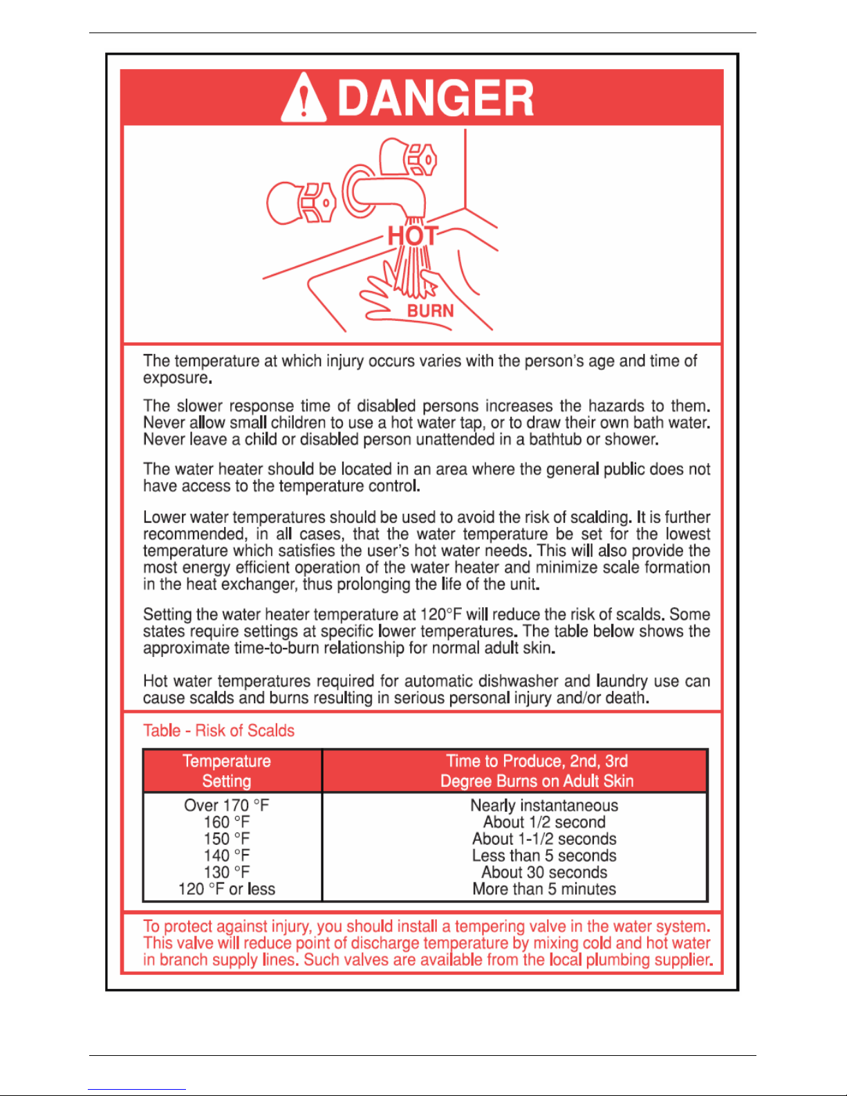
Water temperatures over 125⁰F can cause severe burns instantly or death from scalding. If the proposed water
heater outlet temperature is above 125⁰F, a thermostatically controlled mixing valve (or a temperature limiting
valve) for reducing point of use water temperature is recommended to reduce the risk of scald injury. Contact a
licensed plumber or the local plumbing authority for further information.
The appliance should be located in an area where leakage within the unit or at its connections will not result in
damage to the area adjacent to the appliance or to lower floors of the structure. FLOWMAX will not be
responsible for any damage resulting from leaking if adequate drainage is not provided. When such locations
cannot be avoided, it is recommended that a suitable drain pan, adequately drained, be installed under the
appliance.
Do not use this combination water heater for any purpose other than water heating and space heating.
The flow of combustion air and ventilation to the water heater must not be obstructed. The water heater area
must be kept clear and free from combustible materials, gasoline and other flammable vapours and liquids.
If the water quality is known to be highly acidic and/or extremely hard, water treatments (ie water softeners and
filtration) are recommended to maintain full warranty. Consult the local water authority.
DO NOT over-tighten fittings, as pipe and/or fitting damage may occur causing leakage.
DO NOT install water heater where subject to vibrations.
For other than a direct vent appliance, the appliance must be located as close as possible to a chimney or gas
vent.
Should overheating occur or the gas supply fails to shut off, turn the manual gas control valve to the appliance.
Contact a Service Technician immediately.
Clearance must be in accordance with the local installation codes and the requirements of the gas supplier.
1
GENERAL INFORMATION
Never operate the heater unless it is vented to the outdoors and has adequate air supply to avoid risks of
improper operation, fire, explosion or asphyxiation.
DO NOT install this water heater directly on a carpeted floor. A fire hazard may result. The water heater shall
be installed on a metal or wood panel extending beyond the full width and depth of the water heater by at least 3
inches (76.2mm) in any direction or, if the water heater is installed in an alcove or closet, the entire floor shall be
covered by the panel.
For safe operation, an ample supply of air must be provided for proper combustion and ventilation in accordance
with the National Fuel Gas Code ANSI Z223.1/NFPA 54 National Fuel Gas Code CSA/B149.1 Natural Gas and
Propane Installation Codes or applicable provisions of the local building codes. An insufficient supply of air may
result in a yellow, luminous burner flame, carboning or sooting of the heat exchanger, or create a risk of
asphyxiation. Do not obstruct the flow of combustion and ventilation air.
This unit is not intended to operate at gas supply pressures other than those shown on the rating plate.
Exposure to higher gas supply pressure may cause damage to gas valves, which can result in fire or explosion.
If over-pressure has occurred, such as through improper testing of gas lines or emergency malfunction of the
supply system, the gas valves must be checked for safe operation.
A thermostatic mixing valve must be added to this system to prevent scalding, if regulated by local codes and
authorities.
Check the Rating Plate
FLOWMAX units come from the factory configured for use with natural gas. Prior to installation, check the rating
plate of the water heater to ensure the unit matches gas type, gas pressure, water pressure and electrical
supply. If the unit does not match the requirements, do not install.
Be sure the gas type and electricity voltage match the rating plate.
There is a risk in using fuel burning appliances in rooms or areas where gasoline, other flammable liquids or
engine-driven equipment or vehicles are stored, operate or are repaired. Flammable vapours are heavy and
travel along the floor and may be ignited by the igniter or main burner flames causing fire or explosion. Some
local codes permit operation of gas appliances if installed 18 inches or more above the floor. This may reduce
the risk if location in such an area cannot be avoided. Flammable items, pressurized containers or any other
potential fire hazardous articles must never be placed on or adjacent to the water heater. Open containers of
flammable materials should not be stored or used in the same room with the water heater.
Do not install the FLOWMAX water heater in areas with excessive high humidity.
Do not install the unit in location where there is excessive humidity, such as a bathroom, damp crawl space and
other areas with high levels of humidity. This may cause the unit to malfunction.
To avoid possible electrical shock, DO NOT touch the internal components of the water heater or the power cord
with wet hands.
DO NOT splash excessive water on the water heater when cleaning, as they are water resistant, not water proof.
Professionally qualified personnel in accordance with current laws and standards and in line with the
manufacturer’s instructions must install the appliance.
The commissioning of the water heater and any subsequent works carried out on the appliance must be effected
by an appropriately qualified technician.
The appliance must be used solely for the purpose for which it has been designed and manufactured: central
heating and domestic hot water production. Any other use is deemed as improper and as such dangerous.
Under no circumstances will the manufacturer be held responsible for damage or injury to persons or animals
caused by errors in the installation and/or use of the appliance, or through non-compliance with current local
and national standards and/or the manufacturer’s instructions.
The installation, operation and maintenance manual forms are an integral and essential part of the product and
must be kept with the appliance always.
The warnings contained in this chapter have been written for the appliance user, the installer and the service
technician.
2

GENERAL INFORMATION
The “operating instructions” chapter of this manual must be read carefully as it provides information on the
operation and the operating limits of the appliance.
• After the removal of all the packaging, check that the appliance has not been damaged. In case of doubt, do not
attempt to use the product but refer to the supplier. Packing materials (cardboard box, wooden crate, nails, staples,
plastic bags, polystyrene, etc.) must not be left within reach of children in that these items represent a potential hazard
and must be disposed of in a responsible manner.
• Before carrying out any cleaning or maintenance operations, disconnect the appliance from the mains electricity
supply by switching off at the main switch and/or any other isolating device.
• In the case of a fault and/or malfunction in the appliance, shut down the system. Do not interfere with or attempt any
repairs. Call for professionally qualified technical assistance only.
• Any warranty repairs to the appliance must be carried out exclusively by the manufacturer’s authorized service dealers
using original spare parts. Non-compliance with the above requirements may compromise the safety of the appliance
and invalidate the warranty. In order to guarantee the efficiency of the appliance and its correct operation, it must be
serviced regularly by professionally qualified personnel in line with the manufacturer’s instructions.
• Only original accessories or optional extras (including electrical parts) must be used with the appliance.
• Should there be a smell of gas present in the room where the appliance is installed, DO NOT attempt to activate any
electric switches, telephones or any other equipment that may cause sparks. Open doors and windows immediately to
create a current of air and ventilate the room. Shut-off the main gas supply valve (at the meter), or on the cylinder in
the case of bottled gas, and call an authorized service centre.
• Do not attempt to interfere with the appliance in any way.
• As dictated by current legislation, this appliance must be installed exclusively by qualified personnel. Before
starting the water heater for the first time, make sure that it is connected to a water supply and central heating system
compatible with its performance characteristics.
• Prior to start-up, the central heating pipes should be flushed to remove any residues that could compromise the
operation of the appliance.
• The domestic power supply must be checked by a qualified electrician to ensure that it can support the maximum
power absorption of the appliance, as indicated on the appliance rating plate (positioned on the casing). In particular,
make sure that the cable ratings are adequate for the power absorbed.
• Do not use adapters; multiple sockets or extension leads to connect the appliance to the power supply.
• The appliance must be connected to the mains power supply through an appropriate electrical isolator in accordance
with the current wiring regulations.
• If the cable is damaged in any way, switch off the appliance and have the cable replaced by a suitably qualified
technician.
• When the appliance is no longer required for use, switch off the main power supply, to switch all electrical
components off (circulating pump, burner, etc).
3

GENERAL INFORMATION
Important: Carbon Monoxide Detectors
Many jurisdictions require the installation of carbon monoxide detectors in building where a side wall vented fuel burning
appliance is installed. Installers must abide by local code requirements regarding the installation of CO detectors. The use
of a certified carbon monoxide detector is recommended but not required by FLOWMAX.
“In the State of Massachusetts only”
(a)For all horizontally vented gas fuelled equipment installed in every dwelling, building or structure used in whole or in
part for residential purposes, including those owned and operated by the Commonwealth and where the side wall exhaust
vent termination is less than seven (7) feet above finished grade in the area of the venting, including but not limited to
decks and porches, the following requirements shall be satisfied:
1. INSTALLATION OF CARBON MONOXIDE DETECTORS. At the time of installation of the side wall horizontal
vented gas fuelled equipment, the installing plumber or gas fitter shall observe that a hard wired
monoxide detector
equipment is to be installed and on each additional level of the dwelling, building or structure served by the
equipment. It shall be the responsibility of the property owner to secure the services of qualified licensed
professionals for the installation of hard wired carbon monoxide detectors.
a. In the event that the side wall horizontally vented gas fuelled equipment is installed in a crawl space
or an attic, the hard wired carbon monoxide detector with alarm and battery back-up may be
installed on the next adjacent floor level.
b. In the event that the requirements of this subdivision cannot be met at the time of completion of
installation, the owner shall have a period of 30 days to comply with the above requirements;
provided, however, that during said 30 day period a battery operated carbon monoxide detector with
alarm shall be installed.
2. APPROVED CARBON MONOXIDE DETECTORS. Each carbon monoxide detector as required in
accordance with the above provisions shall comply with NFPA 720 and be ANSI/UL 2034 listed and IAS
certified.
3. SIGNAGE. A metal or plastic identification plate shall be permanently mounted to the exterior of the building
at a minimum height of eight (8) feet above grade directly in line with the exhaust vent terminal for the
horizontally vented gas fuelled heating appliance or equipment. The sign shall read, in print size no less than
one-half (1/2) inch in size, “GAS VENT DIRECTLY BELOW. KEEP CLEAR OF ALL OBSTRUCTIONS”.
4. INSPECTION. The state or local gas inspector of the side wall horizontally vented gas fuelled equipment
shall not approve the installation unless, upon inspection, the inspector observes carbon monoxide detectors
and signage installed in accordance with the provisions of 248 CMR 5.08(2)(a) 1 through 4.
with an alarm and battery back-up is installed on the floor level where the gas
carbon
4
GENERAL INFORMATION
5
GENERAL INFORMATION
6
GENERAL INFORMATION
7
GENERAL INFORMATION
8

GENERAL INFORMATION
1.2 Product Conformity
All FLOWMAX water heaters are ETL certified and possess technical and functional characteristics that comply with
the following standards:
Gas fired water heaters also comply with the following directives:
Standard(s) –
American National Standard/CSA Standard for Gas Water Heaters Volume III, Storage Water Heaters with Input
Ratings above 75,000 Btu per Hour, Circulating and Instantaneous. Conforms to ANSI STD Z21.10.3, certified to
CSA STD 4.3.
The materials used such as copper, brass, stainless steel, etc. form a compact, uniform, highly functional unit that
is easy to install and simple to operate. In its simplicity, the wall-mounted appliance is equipped with all the
appropriate accessories required to make it a fully independent water heater capable of satisfying domestic hot
water production and central heating needs. All water heaters are fully inspected and are accompanied by a quality
certificate, signed by the inspector, and a guarantee certificate. This manual must be kept in a safe place and must
accompany the water heater at all times.
FLOWMAX Technologies will not be held responsible for any misinterpretation of this manual resulting
from the inaccurate translation of same.
FLOWMAX Technologies will not be held responsible for the consequences in the case of non-observance
of the instructions contained in this manual or in the case where actions not specifically described herein
are undertaken.
9
TECHNICAL CHARACTERISTCS
2. TECHNICAL CHARACTERISTICS
2.1 Technical data
Model FLOWMAX - 120
Heat Input max
Heat Input min
Heat Output max (122/86°F) kW - BTU/hr 36.64-123670
Heat Output max - 167/140°F kW - BTU/hr 33.42-116724
Heat Output min - 167/140°F kW - BTU/hr 9.73-33208
Efficiency 100% (full load 167/140°F) % 98.3
Central Heating circuit
Central Heating water temperature setting (min-max) °C-F° 30-75 / 25-40 – 86-167 / 77-104
Max. heating working temperature °C-F° 75/167
Expansion tank capacity Gallons 1.58
Max. working pressure (heating) Bar-psi 2.5-37
Min. working pressure (heating) Bar-psi 0.3-4.29
Domestic Hot Water circuit
D.H.W. temperature setting (min-max) °C-F° 35-60 – 95-140
Max. Hot water working pressure Bar-psi 6-86
Min. Hot water working pressure Bar-psi 0.5-7.16
D.H.W. flow rate at ∆T 45⁰F (25⁰C) l/min–gal/hr 20.0-5.3
D.H.W. flow rate at ∆T 72⁰F (22⁰C) l/min–gal/hr 12.1-3.2
Dimensions (Water heater casing size)
Width in 16.1
Height in 28.7
Depth in 12.2
Weight (net) lbs 101
Hydraulic connections
Central Heating Flow connection NPT 3/4"
Central heating Return connection NPT 3/4"
Cold water mains connection NPT 1/2"
D. Hot water connection NPT 1/2"
Gas connection NPT 1/2"
Gas Supply
Natural gas G 20
Inlet pressure mbar-psi 20-0.29
Gas consumption m3/h-ft3/h 3.6-127.1
Electrical specifications
Power supply V/Hz 120/60
Electrical power consumption W 170
kW - BTU/hr 34-116013
kW - BTU/hr 10-34121
10
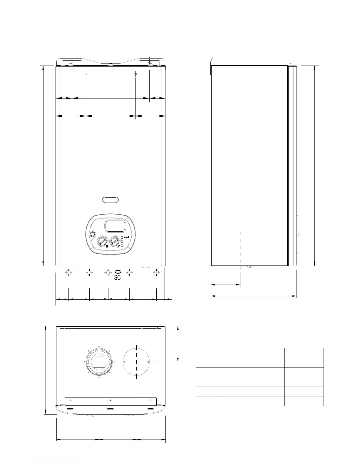
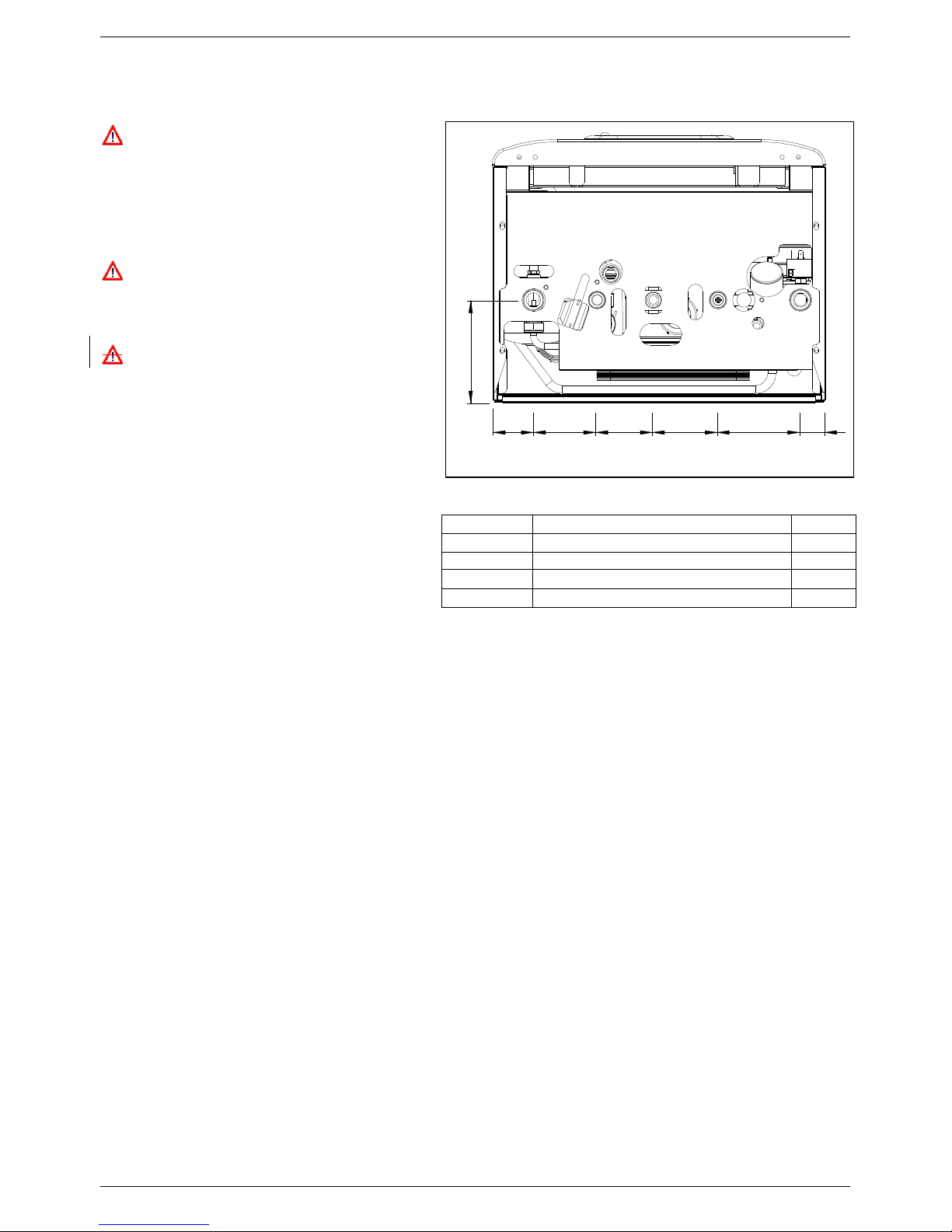
2.2 Dimensions
1.9 12.3 1.9
TECHNICAL CHARACTERISTCS
4.47.34.4
28.7
HI HWO
1.9 3.1 4 1.2
G
2.7 3.2
CWI
HO
4.9
12.2
28.7
12.2
5.2
LEGEND
HI
HO
G
CWI
HWO
SC
HEATING INLET Ø 3/4"
HEATING OUTLET Ø 3/4"
GAS Ø 1/2"
Ø 1/2
Ø 1/2
"
"
COLD WATER INLET
HOT WATER OUTLET
CONDENSATE DRAIN Ø 0.98 in
4.35.46.4
11
TECHNICAL CHARACTERISTCS
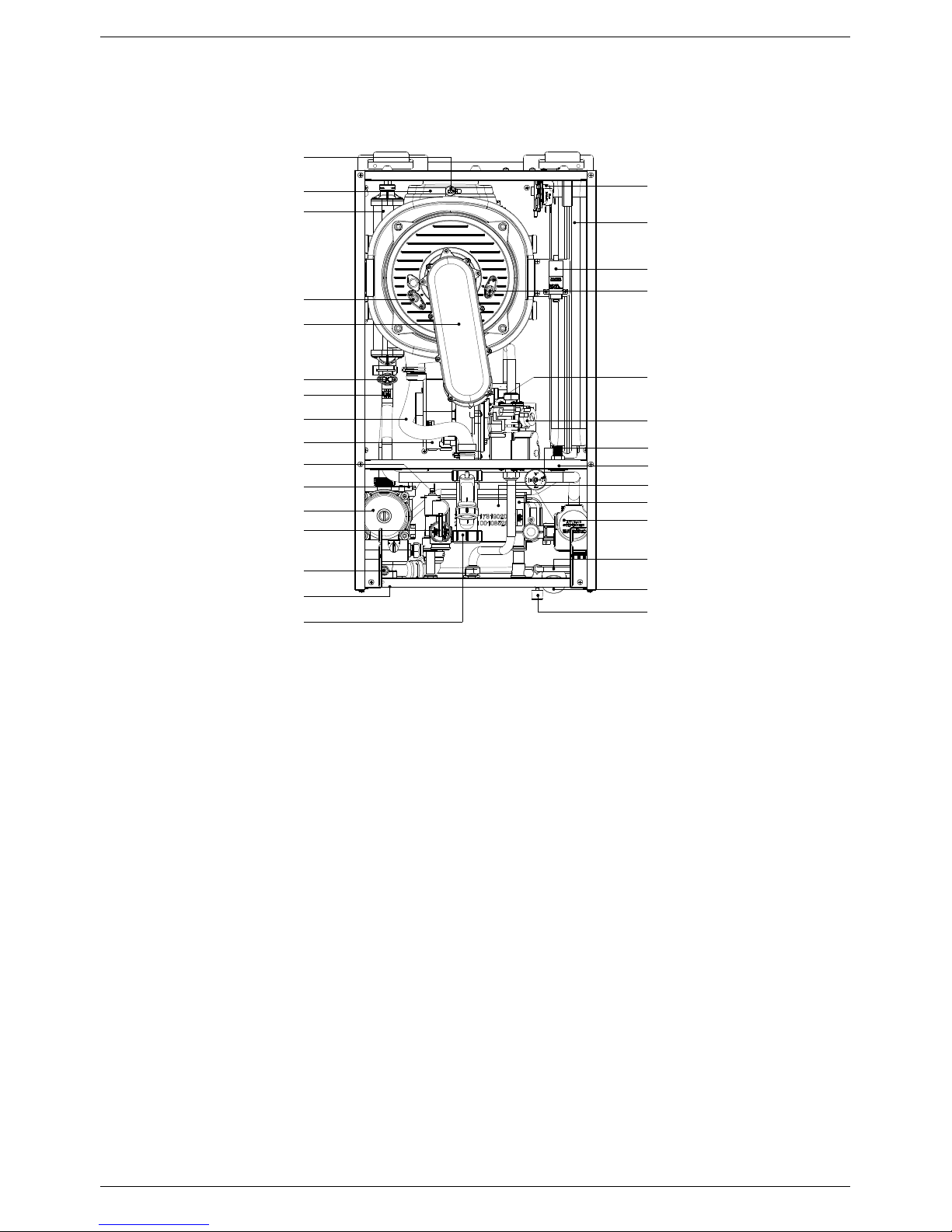
2.3 Internal parts of the water heater
LEGEND
1. PRIMARY CONDENSING HEAT EXCHANGER
2. PREMIX BURNER UNIT (GAS MANIFOLD + BURNER)
3. CONDENSATE DRAIN PIPE
4. IONISATION ELECTRODE
5. IGNITION ELECTRODE
6. FAN
7. VENTURI
8. IGNITION TRANSFORMER
9. ELECTRONIC GAS VALVE
10. SAFETY VALVE 3/4"
11. AUTOMATIC AIR VENT VALVE
12. HEATING SAFETY THERMOSTAT
13. HEATING SENSOR
14. PUMP WITH AIR VENT
15. WATER PRESSURE SWITCH
16. FLUE HOOD
17. SAFETY THERMOFUSE
18. EXPANSION VESSEL
19. D.H.W. SENSOR
20. CONDENSATE TRAP
21. WATER PRESSURE GAUGE
22. AUTOMATIC BY-PASS
23. AIR PRESSURE SWITCH
24. SYSTEM DRAIN VALVE
25. ROOM SEAL CHAMBER BACK SIDE
26. DIVERTER VALVE ACTUATOR UL/CSA
27. ELECTRONIC FLOWSWITCH
28. DHW EXCHANGER
29. FILLING TAP
30. NO-RETURN VALVE
17
16
1
4
2
12
13
3
6
19
11
14
10
22
24
20
23
18
8
5
7
9
15
25
28
27
26
30
21
29
12
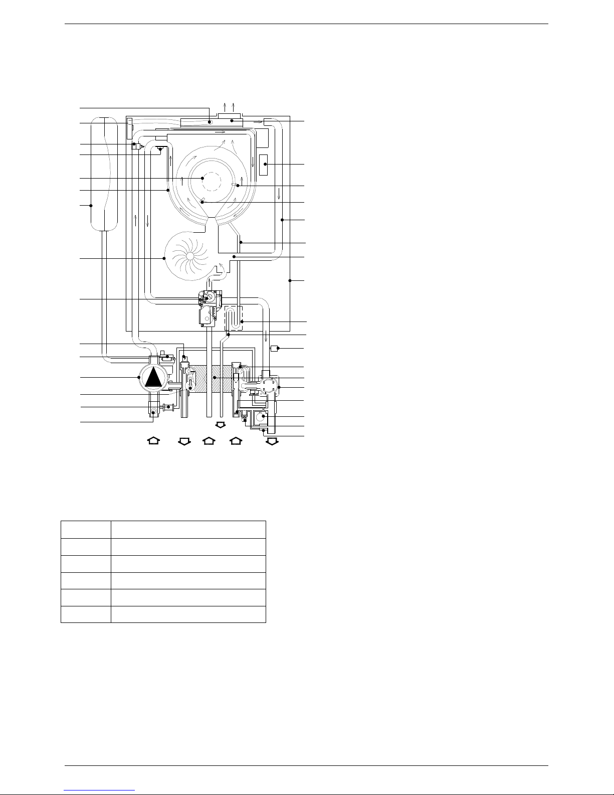
2.4 Water circuit
17
31
13
12
2
1
18
6
9
19
11
14
10
22
24
HI HO
LEGEND
HWO CWIG
SC
TECHNICAL CHARACTERISTCS
16
8
5
4
19
3
7
25
20
23
15
27
28
29
26
21
30
32
1. PRIMARY CONDENSING HEAT
2. PREMIX BURNER UNIT (GAS
3. CONDENSATE DRAIN PIPE
4. IONISATION ELECTRODE
5. IGNITION ELECTRODE
6. FAN
7. VENTURI
8. IGNITION TRANSFORMER
9. ELECTRONIC GAS VALVE
10. SAFETY VALVE 3/4"
11. AUTOMATIC AIR VENT VALVE
12. HEATING SAFETY THERMOSTAT
13. HEATING SENSOR
14. PUMP WITH AIR VENT
15. WATER PRESSURE SWITCH
16. FLUE HOOD
17. SAFETY THERMO FUSE
18. EXPANSION VESSEL
19. D.H.W. SENSOR
20. CONDENSATE TRAP
21. WATER PRESSURE GAUGE
22. AUTOMATIC BY-PASS
23. CONDENSATE DRAIN PIPE
24. SYSTEM DRAIN VALVE
25. ROOM SEAL CHAMBER BACK SIDE
26. FLOW LIMITER
27. ELECTRONIC FLOWSWITCH
28. DHW EXCHANGER
29. DIVERTER VALVE ACTUATOR UL/CSA
30. FILLING TAP
31. AIR PRESSURE SWITCH
32. NO-RETURN VALVE
LEGEND
EXCHANGER
MANIFOLD+BURNER)
HI HEATING INLET
HO HEATING OUTLET
G
CWI
HWO
SC
GAS
COLD WATER INLET
HOT WATER OUTLET
CONDENSATE DRAIN
13
TECHNICAL CHARACTERISTCS
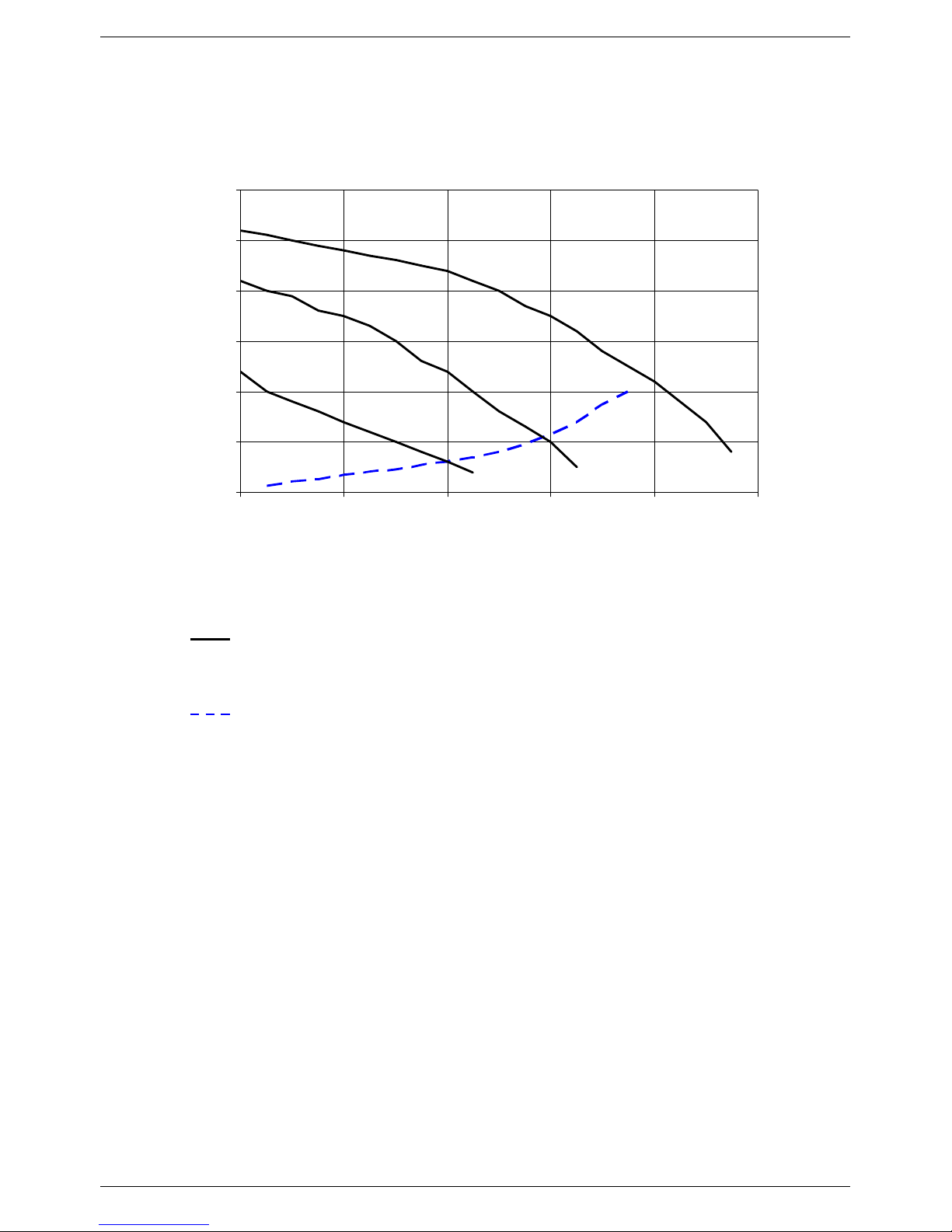
2.5 Circulation pump head/flow graph
30
25
20
15
Head (ft)
10
I
5
0
0 2 4 6 8 10
Water flow (US gpm)
III
II
Pump head
I, II, III Pump speed
Boiler losses
14
TECHNICAL CHARACTERISTCS
2.6 DIGITECH® printed circuit board – SM20021
Technical characteristics
Adjustments possible by service personnel only
• Standard (86-167°F) / reduced (77-104°F) central heating temperature
• Water hammer prevention function
• Central Heating timer - (adjustable from 0 to 7,5 minutes)
• Central Heating pump overrun timer
• Domestic Hot Water pump overrun timer
• Minimum Gas pressure setting
• Maximum Heating Load
• D.H.W. temperature setting 95-160°F
User settings
• On/Off
• Heating Temperature setting (86-167°F) – (77-104°F)
• D.H.W. temperature setting (95-140°F) – (95-160°F)
• Summer only mode / Winter only mode / Summer + Winter mode selection
Operation/Functions display
• Lock-Out
• Water deficiency indicator
• Temperature display
When the water heater is switched off at the switch on the control panel, the word OFF appears on the
display. The D.H.W and central heating frost protection system, nevertheless, remain enabled. If the
water heater was previously on, it is switched off and the post-ventilation, pump overrun circulation
pump and three-way valve inactivity protection functions are enabled.
The remote control, where fitted, remains active and illuminated.
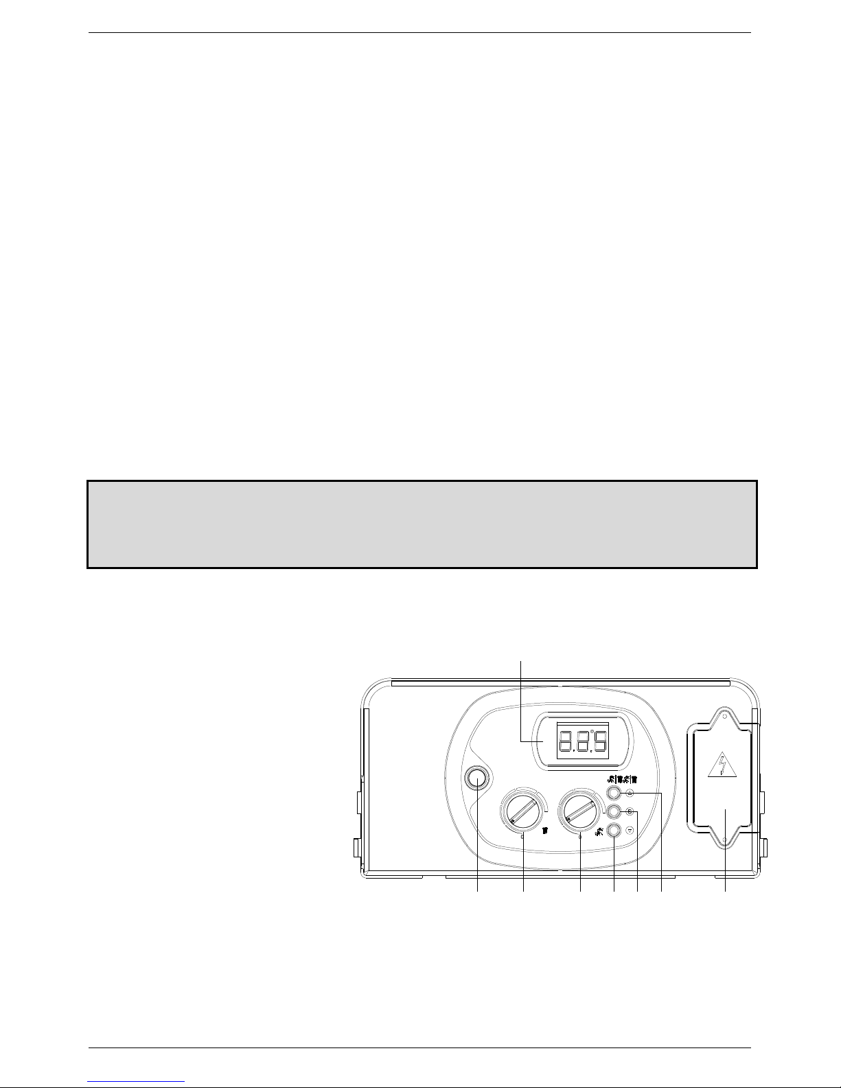
2.7 Control panel
LEGEND
1. ON/OFF SWITCH
2.
HEATING TEMPERATURE CONTROL
KNOB
3. D.H.W TEMPERATURE CONTROL KNOB.
4. D.H.W TEMPERATURE BUTTON. KEEP
PRESSED FOR 5 SECONDS TO DISPLAY
OUTSIDE TEMPERATURE (ONLY WITH
OPTIONAL OUTDOOR SENSOR)
5. SERVICE BUTTON.
6. WINTER MODE SELECTION BUTTON.
7. TERMINAL BOARD FOR EXTERNAL
WIRING.
8. TEMPERATURE, ERROR CODE AND
OPERATING STATUS DISPLAY
8
120 60 Hz
6 754321
15

INSTALLATION INSTRUCTIONS
3. INSTALLATION (authorized personnel)
3.1 Reference standard
Install in accordance with local building and electrical codes.
This appliance meets the requirements of:
Standard(s) –
American National Standard/CSA Standard for Gas Water Heaters Volume III, Storage Water Heaters With Input Ratings
Above 75,000 Btu per Hour, Circulating and Instantaneous.
4.3.
Failure to install a gas appliance correctly and in accordance with the above norms could lead to prosecution. It is in the
interest of the installer and safety that the law is complied with.
The manufacturer’s instructions form an integral part of the installation and should be left with the appliance but do not
over ride in anyway statutory obligations.
Installation requirements
Please refer to local and national standards in force with the Country of destination of the product.
Conforms to ANSI STD Z21.10.3, certified to CSA STD
16
INSTALLATION INSTRUCTIONS
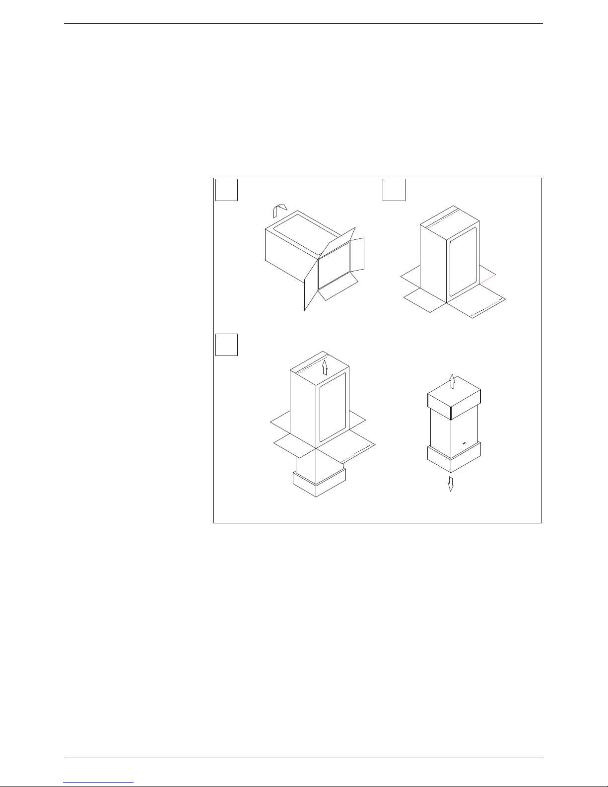
3.2 Unpacking
■ The materials (cardboard) used for packing the appliance are fully recyclable.
■ It is recommended that the packing material is only removed prior to installing the water heater. The
manufacturer will not be held responsible for damage caused by incorrect storage of the product.
■ Packing materials (plastic bags, polystyrene, nails, etc.) must not be left within reach of children, in that
these items represent a potential hazard.
A. Place the packed
appliance on the floor (see fig.
1) making sure that the "up”
arrow is facing down. Remove
the staples and open out the
four flaps of the box.
B. Rotate the water heater 90°
while manually supporting it
from underneath
C. Lift the box and remove the
protections. Lift the water
heater by grasping the rear
part and proceed with the
installation.
STORAGE & HANDLING
Please note that prior to
installation the FLOWMAX
water heaters should be
stored in the horizontal
position with no more than
three water heaters to a stack;
Ensure that the water heaters
are stored in dry conditions
and be aware that the carton is
a two-man lift;
A
C
Fig. 1
B
17
INSTALLATION INSTRUCTIONS
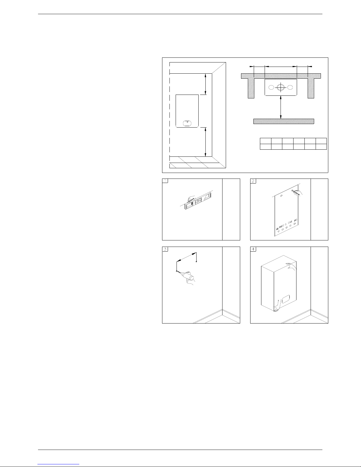
3.3 Installing the water heater
■ The appliance must be installed
exclusively on a flat vertical solid wall
capable of supporting its weight.
■ The water heater should be fitted within
the building unless otherwise protected
by a suitable enclosure i.e. garage or
outhouse. (the water heater may be fitted
inside a cupboard).
■ If the water heater is sited in an unheated
enclosure then it is recommended to
leave the power on to give frost
protection (frost protection is active even
with on/off switch in off position).
■ If a water heater is installed in a closed
water supply system, such as one having
a back flow preventer in the cold water
supply line, means shall be provided to
control thermal expansion. Contact the
water supplier or local plumbing inspector
on how to control this situation.
X
A
B
M od el
FL O W MA X - 12 0
L
M INI MU M D IST AN CE S [IN C H E S]
0 0
Y
H
HLYX
16
2 4
BA
1 2
12
Fig. 1
In order to allow access to the interior of the
water heater for maintenance purposes, it is
important that the necessary clearances
indicated in figure 1 are respected. To make
the installation easier, the water heater is
supplied with a template to enable the pipe
connections to be positioned prior to fixing
the appliance to the wall.
To install the water heater, proceed as
follows (see fig. 2):
a. Use a spirit level (of not less than 25 mm
long) to mark a horizontal line on the wall
where the water heater is to be fitted.
b. Position the top of the template along the
line drawn with the level, respecting the
distances indicated. Then mark the
centres of the positions of the two wallplugs or anchors. Finally, mark the
positions of the water and gas pipes.
c. Remove the template and install the
supplied bracket securely to the wall.
Once the water heater is securely
installed, connect the domestic hot and
cold water pipes, the gas supply pipe and
the central heating pipes using the fittings
supplied with the water heater.
d. Clearance to Combustibles-
Front –0 inches
Sides – 0 inches
Rear – 0 inches
Top – 0 inches from jacket cover
Fig. 2
18
3.4 Water connections
In order to safeguard the heat exchanger
and circulation pump, especially in case
of water heater replacement, it is
recommended that the system is hotflushed to remove any impurities
(especially oil and grease) from the pipes
and radiators.
Make sure that the domestic water and
central heating pipes are not used to
ground the electrical system. The pipes
are totally unsuitable for this purpose.
INSTALLATION INSTRUCTIONS
Isolation Valves must be installed on the
heating and D.H.W circuits. This will
facilitate all maintenance and service
operations where the hot water needs to
be drained.
■ To prevent vibration and noise coming from
the system, do not use pipes of reduced
diameter, short radius elbows or severe
reductions in the cross sections of the water
passages.
■
In order to guarantee the reliability of the
water heater and prevent permanent damage
in areas with high water inlet pressure too, a
36.3 psi (2.5 bar) pressure reducing valve
should be fitted.
The water flowing out of the pressure/relief valve during its operation may be extremely hot. Before operating relief
valve, make sure drain line is installed to direct discharge to a safe location such as an open drain. Avoid scalding
and/or water damage.
A pressure relief valve is installed in this dual purpose water heater that is rated in accordance with and complying
with either The Standard for relief Valves and Automatic Shutoff Devices for Hot Water Supply Systems, ANSI
Z21.22 CSA 4.4 Code.
The relief valve must be installed such that the discharge will be conducted to a suitable place for disposal when
relief occurs and that no reducing coupling or other restriction be installed in the discharge line. The discharge line
must be installed to allow complete drainage of both the valve and the line. If this unit is installed with a separate
storage vessel, the separate vessel must have its own temperature and pressure relief valve. No valve is to be
placed between the relief valve and the tank. This valve must also comply with The Standard for Relief Valves and
Automatic Shutoff Devices for Hot Water Supply Systems. ANSI Z21.22 or CSA 4.4. If a relief valve discharges
periodically, this may be due to thermal expansion in a closed water system. Contact the water supplier or local
plumbing inspector on how to correct this situation. Do not unplug relief valve.
4.9
1.9 3.1 4 1.2
Fig. 1
LEGEND
HI HEATING INLET
HO HEATING OUTLET
G GAS
CWI COLD W ATER INLET
HWO HOT WATER OUTLET
HI HWO G CWI HO
2.7 3.2
Ø 3/4"
Ø 3/4"
Ø 1/2"
Ø 1/2"
Ø 1/2"
19
INSTALLATION INSTRUCTIONS
3.5 Domestic hot water circuit/ Condensate Drain
Warning/ Hard Water
If this water heater is installed in an application where the supply water is hard, it must be treated with either
a water softener and filtration, which removes the hardness, or by using sequestering agents that reduce
the amount of scale deposits.
Damage to the water heater as a result of water in excess of 14.5 gpg (250mg/L) of hardness is not
covered by FLOWMAX Limited warranty. If there a problem with the water quality, contact your local water
conditioning company for equipment to condition the water supply to this appliance
The cold water supply pressure at the inlet to the water heater must be between 7.25 psi (0.5 bar) and 87 psi
(6 bar).
In areas with higher water inlet pressure a pressure reducing valve must be fitted before the water heater.
The frequency of the heat exchanger coil cleaning depends on the hardness of the mains water supply and the
presence of residual solids or impurities, which are often present in the case of a new installation. If the
characteristics of the mains water supply are such that require it to be treated, then the appropriate treatment
devices must be installed, while in the case of residues, an in-line filter should be sufficient.
Central heating circuit
In order to prevent scaling or deposits in the primary heat exchanger, the mains supply water to the heating circuit
must be treated according to the requirements of local standards.
This treatment is indispensable in the case where the circuit is frequently topped-up or when the system is often
either partially or fully drained.
Condensate Drain
■ FLOW MAX water heater is a high efficient gas appliance that creates condensation when it operates. A
condensate trap and flexible drain pipe comes factory installed inside each water tank.
The condensate trap must be primed before operation to prevent exhaust gases from entering the building.
■ Follow your local code with regards to the disposal of condensation
■ Here are several options for disposal of condensate
o From combination water heater direct to drain
o From combination water heater to neutralizer to drain
o From combination water heater to laundry tub (bottom of water heater must be above the height of
the laundry tub; must have a negative slope to properly drain)
o From combination water heater to condensate pump to laundry tub (for long distances between
water heater and laundry tub or when bottom of the water heater is installed below height of the
laundry tub)
■ Failure to install the condensate discharge properly will affect the reliability of the water heater.
For all units installed with vertical exhaust, must have an additional approved condensate drain. Fittings
must be ULC S636 approved.
Failure to properly connect the condensate line will cause combustion gases to enter the room, possibly
causing serious injury to occupants or death.
Note: Check with your municipality, local codes, or local gas company to determine if disposal of
combustion condensate is permitted. In the State of Massachusetts the condensate must be
neutralized prior to entering a drain
■ Use only PVC, vinyl or CPVC pipe for the condensate drain line, metal pipe work is not suitable for
condensate discharge system.
■ The condensate drain line should be a minimum of 1/2” diameter that connects to the 7/8” diameter
supplied hose and must be supported to prevent sagging. Manufacturer will supply a ¾” to ½” reducer for
connection.
■ Keep the length of the condensate drain as short as possible. Long runs or applications where the nearest
drain is above the water heater will require the use of a condensate pump. Size the pump to allow for a
20

INSTALLATION INSTRUCTIONS
maximum condensate discharge of 2 gpm from the water heater. The end drain pipe must not be
submerged in water or blocked in any way.
■ The condensate pump must be installed with an overflow safety switch that detects downstream clogs and
shuts off the water heater before flooding occurs. See condensate pump manufacture for installation
instructions.
■ The condensate pump must be installed with an overflow safety switch that detects downstream clogs and
shuts off the water heater before flooding occurs. See condensate pump manufacture for installation
instructions.
■ Be sure to check that condensate is freely flowing from the drain piping after the system has been installed.
Condensate will begin flowing out of the water heater within 15 minutes after operation has started.
■ Do not run condensate line outside and take measures to prevent the condensate drain lines from freezing
(insulation, heat tape, electric heaters, etc.)
■ Be sure to clean the condensate trap at least once per year to prevent any problems, and after cleaning be
sure to check for any leaks of condensed water or flue gas.
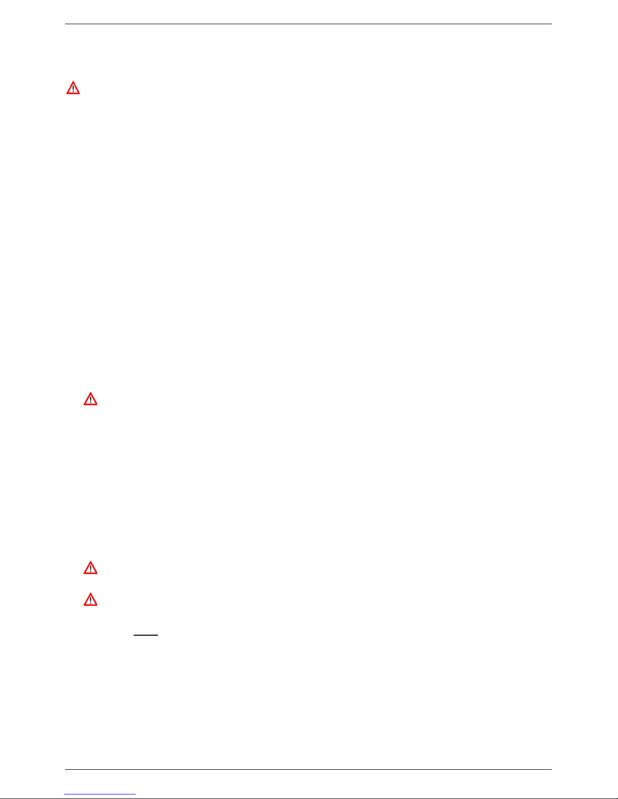
Space Heating
This water heater is suitable for water (potable) heating and space heating.
Piping and components connected to the water heater for the space heating application shall be suitable for
use with potable water.
Toxic chemicals, such as used for water heater treatment, shall not be introduced into the potable water
used for space heating.
A water heater which will be used to supply potable water shall not be connected to any heating system of
component(s) previously used with nonpotable water heating appliance.
When the system requires water for the space heating at temperatures higher than required for other uses,
a means such as a mixing valve shall be installed to temper the water for those uses in order to reduce
scald hazard potential.
The water heater can be used for potable hot water heating and combination space heating applications.
Note: the following illustrations are conceptual designs only. There are many design variations of the equipment
presented. Designers must add all necessary safety and auxiliary equipment to conform to Code requirement and
proper design practice. For more details, contact the manufacturer or distributors of the products.
21
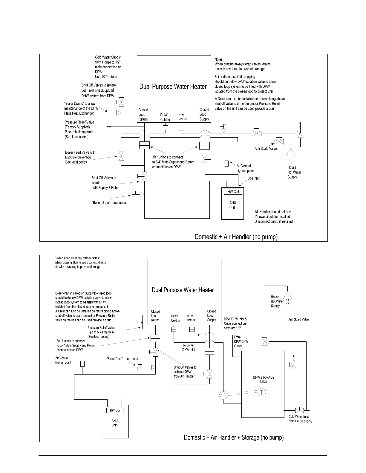
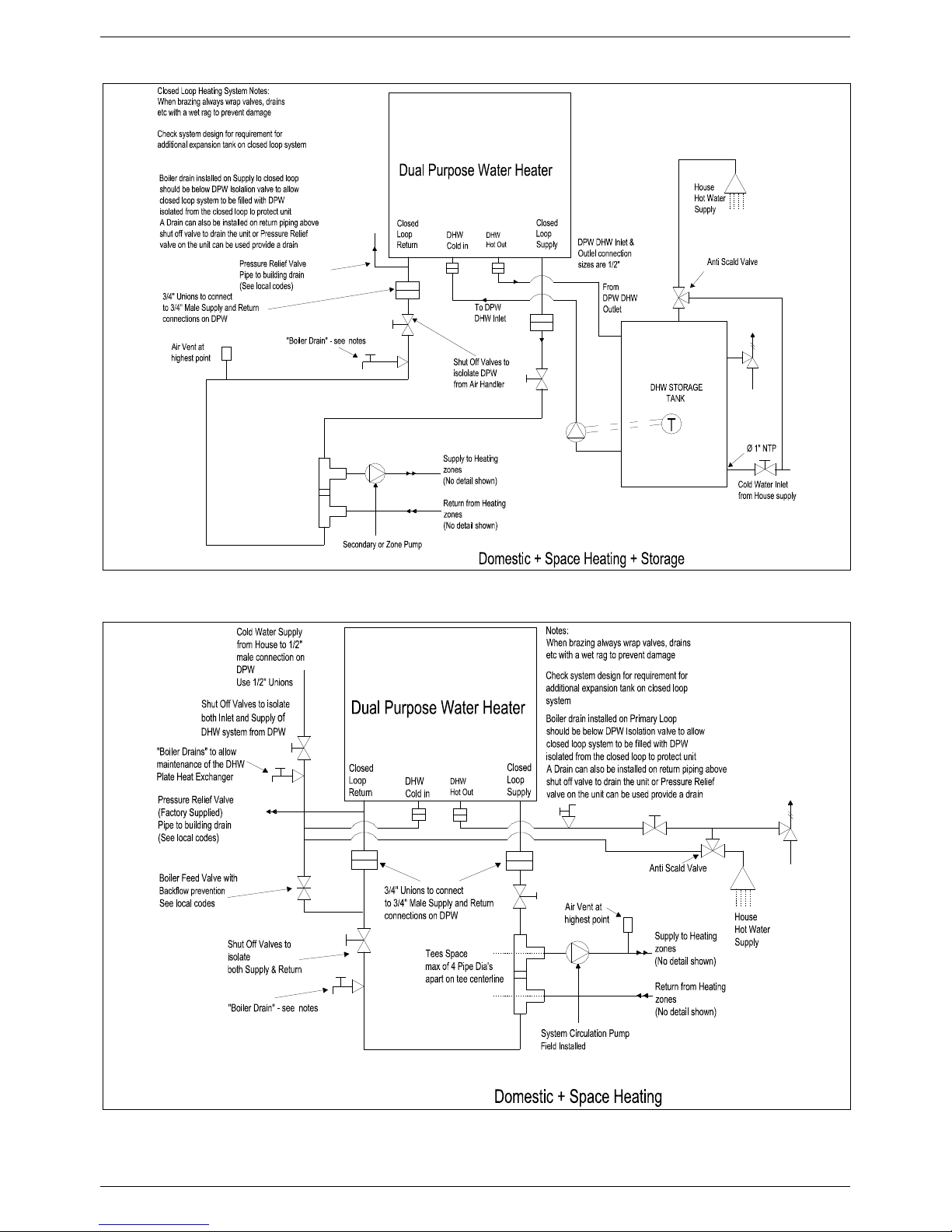
INSTALLATION INSTRUCTIONS
3.6 Schematic of Piping Installation
22
INSTALLATION INSTRUCTIONS
23
 Loading...