

Instruction Manual
for model
FLOWMAX – 90
Nordgas Version
Condensing water heater
85,000 BTU
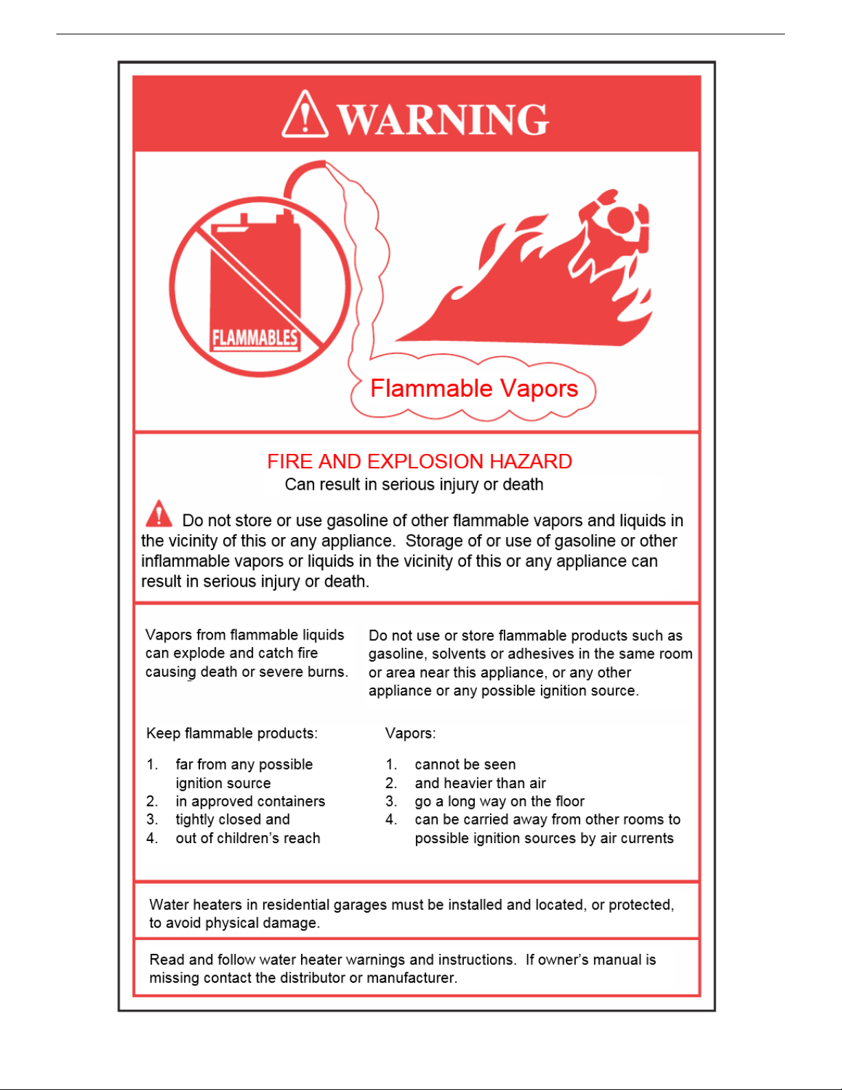
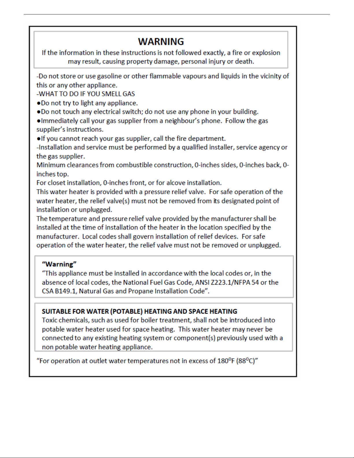
WARNING
If the information in these instructions is not followed exactly, a fire or explosion may result, causing property damage, personal injury or death.
-Do not store or use gasoline or other flammable vapours and liquids in the vicinity of this or any other appliance.
-WHAT TO DO IF YOU SMELL GAS
●Do not try to light any appliance.
●Do not touch any elect rica l switc h; do not use any phone in your building.
●Immediately call yo ur gas supplier fro m a neighbour’s pho ne. Fo llow the gas s upplier’s instructions.
●If you cannot reach your gas supplier, call the fire department.
-Installation and service must be performed by a qualified installer, service agency or the gas supplier.
Installation, operating, commissioning and maintenance instructions.
Water heaters for other than recreational vehicle installation


CONTENTS
Pages
General information
1.1 General warnings 1
1.2 Product conformity 9
2. Technical characteristics
2.1 Technical data 10
2.2 Dimensions 11
2.3 Internal parts of the water heater 12
2.4 Water circuit 13
2.5 Circulation pump head/flow graph 14
2.6 Printed circuit board – Technical characteristics 15
2.7 Control panel 16
3. Installation (authorized personnel)
3.1 Reference standard 18
3.2 Unpacking 19
3.3 Installing the water heater 20
3.4 Water connections 21
3.5 Domestic Hot Water Circuit/Hard Water Warning/ Condensate Drain 22
3.6 Schematic of Piping Installation 24
3.7 Gas connection 26
3.8 Electrical connections
27
3.9 Venting connections 29
4. Commissioning the appliance (authorized personnel)
4.1 General warnings 36
4.2 Filling the system 37
4.3 Flushing the system 38
4.4 Filling the condensate trap 38
4.5 Starting up the water heater 39
5. Regulating the appliance (authorized personnel)
5.1 Parameters table 40
5.2 Setting the parameters 42
5.3 Gas Data 51

CONTENTS
6. Maintenance (authorized personnel)
6.1 General warnings 52
6.2 Maintenance 52
6.3 Water heater inspection 52
6.4 Accessing the water heater 54
6.5 Flushing out the primary side 54
6.6 Draining the central heating and domestic hot water system 55
6.7 Maintenance operations 56
6.8 Wiring diagrams 63
6.9 D.H.W Sensor Connection 66
6.10 Troubleshooting 67
6.11 Diagnostics 68
6.12 Parts list 82
7. Warranty
Pages
7.1 Terms and Condition of Sale 84
7.2 Warranty Registration Form 86
7.3 Warranty Part Request Form 87

GENERAL INFORMATION
1. GENERAL INFORMATION
1.1 General warnings – Installation
Read all safety warnings in the “Instruction Manual”. The additional safety issues outlined below must also be
followed completely when installing this FLOWMAX Combination Water heater.
Failure to remove or maintain the area free of combustible material, gasoline and other flammable liquids or vapours
can result in severe personal injury, death or substantial property damage.
All applicable local, state, national and provincial codes, ordinances, regulations and laws must be observed.
For installations in Massachusetts – code requires the units to be installed by a licensed plumbing or gas fitter.
The appliance cannot operate without the correct amount of air for combustion. Please make sure there is sufficient
inflow and outflow of air for ventilation, never obstruct the flow of ventilation air. Failure to provide the proper amount
of combustion air can result in a fire or explosion and cause death, serious bodily injury or property damage.
If an external electrical source is utilized, the appliance, when installed, must be electrically grounded in accordance
with local codes or, in the absence of local codes, with the National Electrical Codes ANSI/NFPA 70 and or the CSA
C22.1 Canadian Electrical Code.
Follow all local codes and/or the most recent edition of the National Fuel Gas Code (ANSI Z223.1/NFPA 54) in the
USA or the Natural Gas and Propane Installation Code in Canada (CAN/CSA B149.1).
This unit is designed for indoor installations. DO NOT operate this unit without the vent piping connected. Exhaust
gases must be completely expelled out of the building.
Do not use this appliance if any part has been underwater. Immediately call a qualified service technician to inspect
the appliance and replace any part of the control system and any gas control which has been underwater.
Be sure not to reverse the water and gas connections as this may damage the gas valves.
Water temperatures over 125⁰F can cause severe burns instantly or death from scalding. If the proposed water
heater outlet temperature is above 125⁰F, a thermostatically controlled mixing valve (or a temperature limiting valve)
for reducing point of use water temperature is recommended to reduce the risk of scald injury. Contact a licensed
plumber or the local plumbing authority for further information.
The appliance should be located in an area where leakage within the unit or at its connections will not result in
damage to the area adjacent to the appliance or to lower floors of the structure. FLOWMAX will not be responsible
for any damage resulting from leaking if adequate drainage is not provided. When such locations cannot be
avoided, it is recommended that a suitable drain pan, adequately drained, be installed under the appliance.
Do not use this combination water heater for any purpose other than water heating and space heating.
The flow of combustion air and ventilation to the water heater must not be obstructed. The water heater area must
be kept clear and free from combustible materials, gasoline and other flammable vapours and liquids.
If the water quality is known to be highly acidic and/or extremely hard, water treatments (ie water softeners and
filtration) are recommended to maintain full warranty. Consult the local water authority.
DO NOT over-tighten fittings, as pipe and/or fitting damage may occur causing leakage.
DO NOT install water heater where subject to vibrations.
For other than a direct vent appliance, the appliance must be located as close as possible to a chimney or gas vent.
Should overheating occur or the gas supply fails to shut off, turn the manual gas control valve to the appliance.
Contact a Service Technician immediately.
Clearance must be in accordance with the local installation codes and the requirements of the gas supplier.
1

GENERAL INFORMATION
Never operate the heater unless it is vented to the outdoors and has adequate air supply to avoid risks of improper
operation, fire, explosion or asphyxiation.
DO NOT install this water heater directly on a carpeted floor. A fire hazard may result. The water heater shall be
installed on a metal or wood panel extending beyond the full width and depth of the water heater by at least 3 inches
(76.2mm) in any direction or, if the water heater is installed in an alcove or closet, the entire floor shall be covered
by the panel.
For safe operation, an ample supply of air must be provided for proper combustion and ventilation in accordance
with the National Fuel Gas Code ANSI Z223.1/NFPA 54 National Fuel Gas Code CSA/B149.1 Natural Gas and
Propane Installation Codes or applicable provisions of the local building codes. An insufficient supply of air may
result in a yellow, luminous burner flame, carboning or sooting of the heat exchanger, or create a risk of
asphyxiation. Do not obstruct the flow of combustion and ventilation air.
This unit is not intended to operate at gas supply pressures other than those shown on the rating plate. Exposure to
higher gas supply pressure may cause damage to gas valves, which can result in fire or explosion. If over-pressure
has occurred, such as through improper testing of gas lines or emergency malfunction of the supply system, the gas
valves must be checked for safe operation.
A thermostatic mixing valve must be added to this system to prevent scalding, if regulated by local codes and
authorities.
Check the Rating Plate
FLOWMAX units come from the factory configured for use with natural gas. Prior to installation, check the rating
plate of the water heater to ensure the unit matches gas type, gas pressure, water pressure and electrical supply. If
the unit does not match the requirements, do not install.
Be sure the gas type and electricity voltage match the rating plate.
There is a risk in using fuel burning appliances in rooms or areas where gasoline, other flammable liquids or engine-
driven equipment or vehicles are stored, operate or are repaired. Flammable vapours are heavy and travel along
the floor and may be ignited by the igniter or main burner flames causing fire or explosion. Some local codes permit
operation of gas appliances if installed 18 inches or more above the floor. This may reduce the risk if location in
such an area cannot be avoided. Flammable items, pressurized containers or any other potential fire hazardous
articles must never be placed on or adjacent to the water heater. Open containers of flammable materials should
not be stored or used in the same room with the water heater.
Do not install the FLOWMAX water heater in areas with excessive high humidity.
Do not install the unit in location where there is excessive humidity, such as a bathroom, damp crawl space, and
other areas with high levels of humidity. This may cause the unit to malfunction.
To avoid possible electrical shock, DO NOT touch the internal components of the water heater or the power cord
with wet hands.
DO NOT splash excessive water on the water heater when cleaning, as they are water resistant, not water proof.
Professionally qualified personnel in accordance with current laws and standards and in line with the manufacturer’s
instructions must install the appliance.
The commissioning of the water heater and any subsequent works carried out on the appliance must be effected by
an appropriately qualified technician.
The appliance must be used solely for the purpose for which it has been designed and manufactured: central
heating and domestic hot water production. Any other use is deemed as improper and as such dangerous. Under
no circumstances will the manufacturer be held responsible for damage or injury to persons or animals caused by
errors in the installation and/or use of the appliance, or through non-compliance with current local and national
standards and/or the manufacturer’s instructions.
The installation, operation and maintenance manual forms are an integral and essential part of the product and must
be kept with the appliance always.
2

GENERAL INFORMATION
The warnings contained in this chapter have been written for the appliance user, the installer and the service
technician.
The “operating instructions” chapter of this manual must be read carefully as it provides information on the operation
and the operating limits of the appliance.
• After the removal of all the packaging, check that the appliance has not been damaged. In case of doubt, do not attempt
to use the product but refer to the supplier. Packing materials (cardboard box, wooden crate, nails, staples, plastic bags,
polystyrene, etc.) must not be left within reach of children in that these items represent a potential hazard and must be
disposed of in a responsible manner.
• Before carrying out any cleaning or maintenance operations, disconnect the appliance from the mains electricity supply by
switching off at the main switch and/or any other isolating device.
• In the case of a fault and/or malfunction in the appliance, shut down the system. Do not interfere with or attempt any
repairs. Call for professionally qualified technical assistance only.
• Any warranty repairs to the appliance must be carried out exclusively by the manufacturer’s authorized service dealers
using original spare parts. Non-compliance with the above requirements may compromise the safety of the appliance and
invalidate the warranty. In order to guarantee the efficiency of the appliance and its correct operation, it must be serviced
regularly by professionally qualified personnel in line with the manufacturer’s instructions.
• Only original accessories or optional extras (including electrical parts) must be used with the appliance.
• Should there be a smell of gas present in the room where the appliance is installed, DO NOT attempt to activate any
electric switches, telephones or any other equipment that may cause sparks. Open doors and windows immediately to
create a current of air and ventilate the room. Shut-off the main gas supply valve (at the meter), or on the cylinder in the
case of bottled gas, and call an authorized service centre.
• Do not attempt to interfere with the appliance in any way.
• As dictated by current legislation, this appliance must be installed exclusively by qualified personnel. Before starting
the water heater for the first time, make sure that it is connected to a water supply and central heating system compatible
with its performance characteristics.
• Prior to start-up, the central heating pipes should be flushed to remove any residues that could compromise the operation
of the appliance.
• The domestic power supply must be checked by a qualified electrician to ensure that it can support the maximum power
absorption of the appliance, as indicated on the appliance rating plate (positioned on the casing). In particular, make sure
that the cable ratings are adequate for the power absorbed.
• Do not use adapters; multiple sockets or extension leads to connect the appliance to the power supply.
• The appliance must be connected to the mains power supply through an appropriate electrical isolator in accordance with
the current wiring regulations.
• If the cable is damaged in any way, switch off the appliance and have the cable replaced by a suitably qualified
technician.
• When the appliance is no longer required for use, switch off the main power supply, to switch all electrical
components off (circulating pump, burner etc.).
3
GENERAL INFORMATION
Important: Carbon Monoxide Detectors
Many jurisdictions require the installation of carbon monoxide detectors in building where a side wall vented fuel burning
appliance is installed. Installers must abide by local code requirements regarding the installation of CO detectors. The use of
a certified carbon monoxide detector is recommended but not required by FLOWMAX.
“In the State of Massachusetts only”
(a)For all horizontally vented gas fuelled equipment installed in every dwelling, building or structure used in whole or in part
for residential purposes, including those owned and operated by the Commonwealth and where the side wall exhaust vent
termination is less than seven (7) feet above finished grade in the area of the venting, including but not limited to decks and
porches, the following requirements shall be satisfied:
1. INSTALLATION OF CARBON MONOXIDE DETECTORS. At the time of installation of the side wall horizontal
vented gas fuelled equipment, the installing plumber or gas fitter shall observe that a hard wired carbon
monoxide detector
is to be installed and on each additional level of the dwelling, building or structure served by the equipment. It
shall be the responsibility of the property owner to secure the services of qualified licensed professionals for the
installation of hard wired carbon monoxide detectors.
a. In the event that the side wall horizontally vented gas fuelled equipment is installed in a crawl space or
an attic, the hard wired carbon monoxide detector with alarm and battery back-up may be installed on
the next adjacent floor level.
b. In the event that the requirements of this subdivision cannot be met at the time of completion of
installation, the owner shall have a period of 30 days to comply with the above requirements; provided,
2. APPROVED CARBON MONOXIDE DETECTORS. Each carbon monoxide detector as required in accordance
with the above provisions shall comply with NFPA 720 and be ANSI/UL 2034 listed and IAS certified.
3. SIGNAGE. A metal or plastic identification plate shall be permanently mounted to the exterior of the building at a
minimum height of eight (8) feet above grade directly in line with the exhaust vent terminal for the horizontally
vented gas fuelled heating appliance or equipment. The sign shall read, in print size no less than one-half (1/2)
inch in size, “GAS VENT DIRECTLY BELOW. KEEP CLEAR OF ALL OBSTRUCTIONS”.
however, that during said 30 day period a battery operated carbon monoxide detector with alarm shall
be installed.
with an alarm and battery back-up is installed on the floor level where the gas equipment
4. INSPECTION. The state or local gas inspector of the side wall horizontally vented gas fuelled equipment shall
not approve the installation unless, upon inspection, the inspector observes carbon monoxide detectors and
signage installed in accordance with the provisions of 248 CMR 5.08(2)(a) 1 through 4.
4

GENERAL INFORMATION
5
GENERAL INFORMATION
6

GENERAL INFORMATION
7
GENERAL INFORMATION
8

GENERAL INFORMATION
1.2 Product conformity
All FLOWMAX water heaters are ETL certified and possess technical and functional characteristics that comply with
the following standards:
Gas fired water heaters also comply with the following standards:
American National Standard/CSA Standard for Gas Water Heaters Volume III, Storage Water Heaters with input
Ratings above 75,000 Btu per Hour, Circulating and Instantaneous. Conforms to ANSI STD Z21.10.3, certified to CSA
STD 4.3.
The materials used such as copper, brass, stainless steel, etc. form a compact, uniform, highly functional unit that is
easy to install and simple to operate. In its simplicity, the wall-mounted appliance is equipped with all the appropriate
accessories required to make it a fully independent water heater capable of satisfying domestic hot water production
and central heating needs. All water heaters are fully inspected and are accompanied by a quality certificate, signed by
the inspector, and a guarantee certificate. This manual must be kept in a safe place and must accompany the water
heater at all times.
FLOWMAX will not be held responsible for any misinterpretation of this manual resulting from the inaccurate
translation of same.
FLOWMAX will not be held responsible for the consequences in the case of non-observance of the
instructions contained in this manual or in the case where actions not specifically described herein are
undertaken.
9
GENERAL INFORMATION
Model FLOWMAX - 90
Heat Input max
kW - BTU/hr
25 – 90 000
Heat Input min
kW - BTU/hr
9 – 35 000
Heat Output max - 122/86°F
kW - BTU/hr
26.7 – 91 019
Heat Output max - 167/140°F
kW - BTU/hr
24.6 – 83 939
Heat Output min - 167/140°F
kW - BTU/hr
8.73 – 29 788
Efficiency 100% (full load 167/140°F)
%
98.4
Central Heating circuit
Central Heating water temperature setting (min-max)
°C – °F
25–40 / 30-75 - 77–104 / 86-167
Max. heating working temperature
°C – °F
75/167
Expansion vessel capacity
ltrs - gal
6 - 1.58
Max. working pressure (heating)
bar - psi
2.1 - 30
Min. working pressure (heating)
bar - psi
0.3 - 4.29
Domestic Hot Water circuit
D.H.W. temperature setting (min-max)
°C – °F
35-72 – 95-160
Max. Hot water working pressure
bar - psi
6 - 86
Min. Hot water working pressure
bar - psi
0.5 - 7.16
D.H.W. flow rate at ∆T 45°F (25°C)
l/min - gal/min
14.10 - 3.72
D.H.W. flow rate at ∆T 72°F (40°C)
l/min - gal/min
8.7 - 2.30
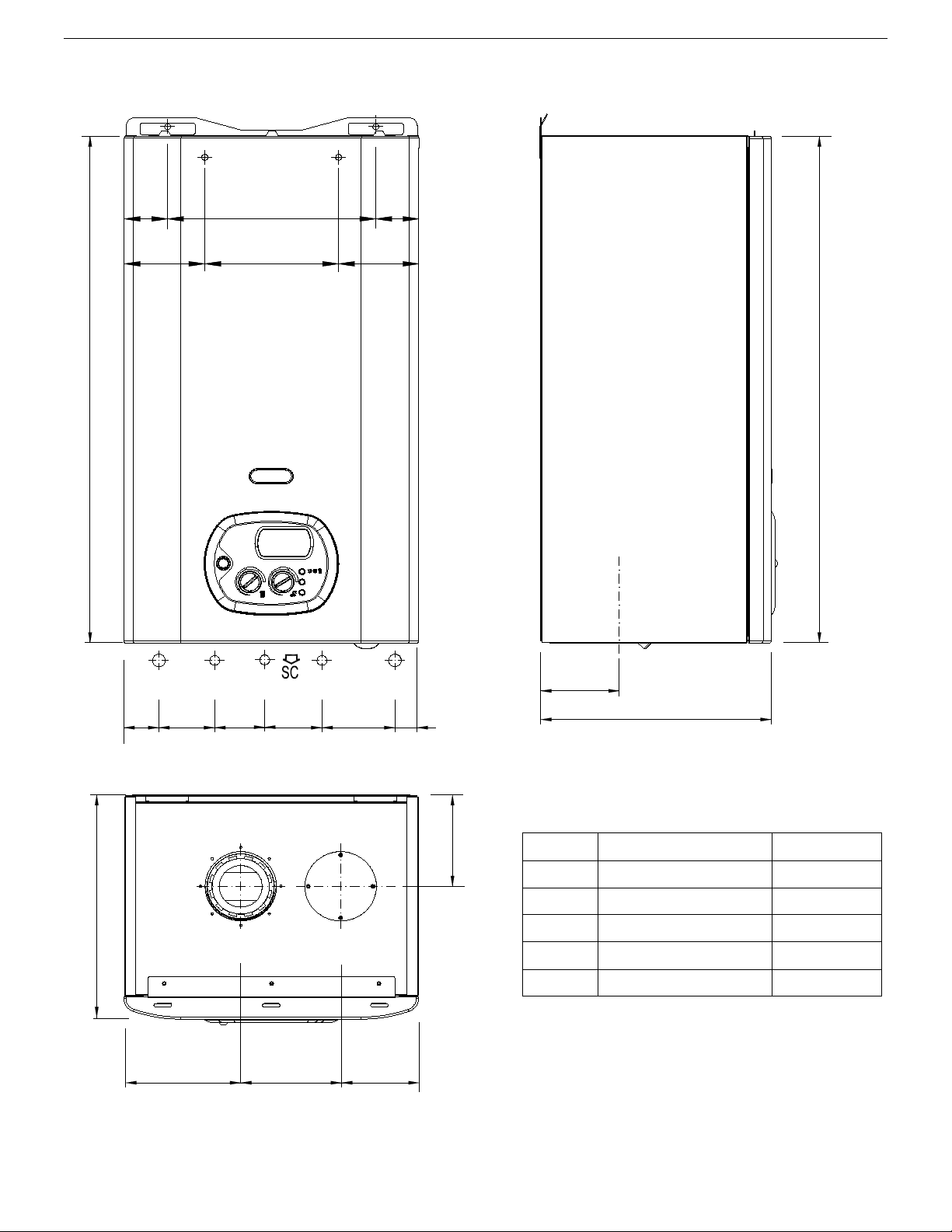
Dimensions (Water heater casing size)
Width
in
16.1
Height
in
28.7
Depth
in
11.2
Weight (net)
lb
84
Hydraulic connections
Central Heating Flow connection
BSPP
3/4"
Central heating Return connection
BSPP
3/4"
Cold water mains connection
BSPP
1/2"
D. Hot water connection
BSPP
1/2"
Gas connection
NPT
1/2"
Gas Supply
Natural Gas (Ng)
Inlet pressure
mbar – in wc
20 - 7
Gas consumption
m3/h - ft3/h
2.65 - 93.58
Liquid Propane (Lp)
Inlet pressure
mbar – in wc
37 – 14
Gas Consumption
m3/h - ft3/h
1.01 – 35.67
Electrical specifications
Power supply
V/Hz
120/60
Electrical power consumption
W
180
2. TECHNICAL CHARACTERISTICS
2.1 Technical data
10
4.3
5.4
6.4
11.2
5.2
28.7
HO
CWI
G
HI
HWO
1.9 3.1
4
1.2
11.2
28.7
4.4
7.3
4.4
1.9
12.3
1.9
4.1
2.7
3.2
LEGEND
HI
HEATING INLET
3/4" BSPP
HO
HEATING OUTLET
3/4" BSPP
G
GAS
1/2" BSPP
CWI
COLD WATER INLET
1/2" BSPP
HWO
HOT WATER OUTLET
1/2" BSPP
SC
CONDENSATE DRAIN
0.98 in
2.2 Dimensions
GENERAL INFORMATION
11
GENERAL INFORMATION
13
24
17
3
2
16
19
20
1
12
7
6
10
14
22
11
4
29
25
5
15
9
18
28
26
27
21
30
8
23
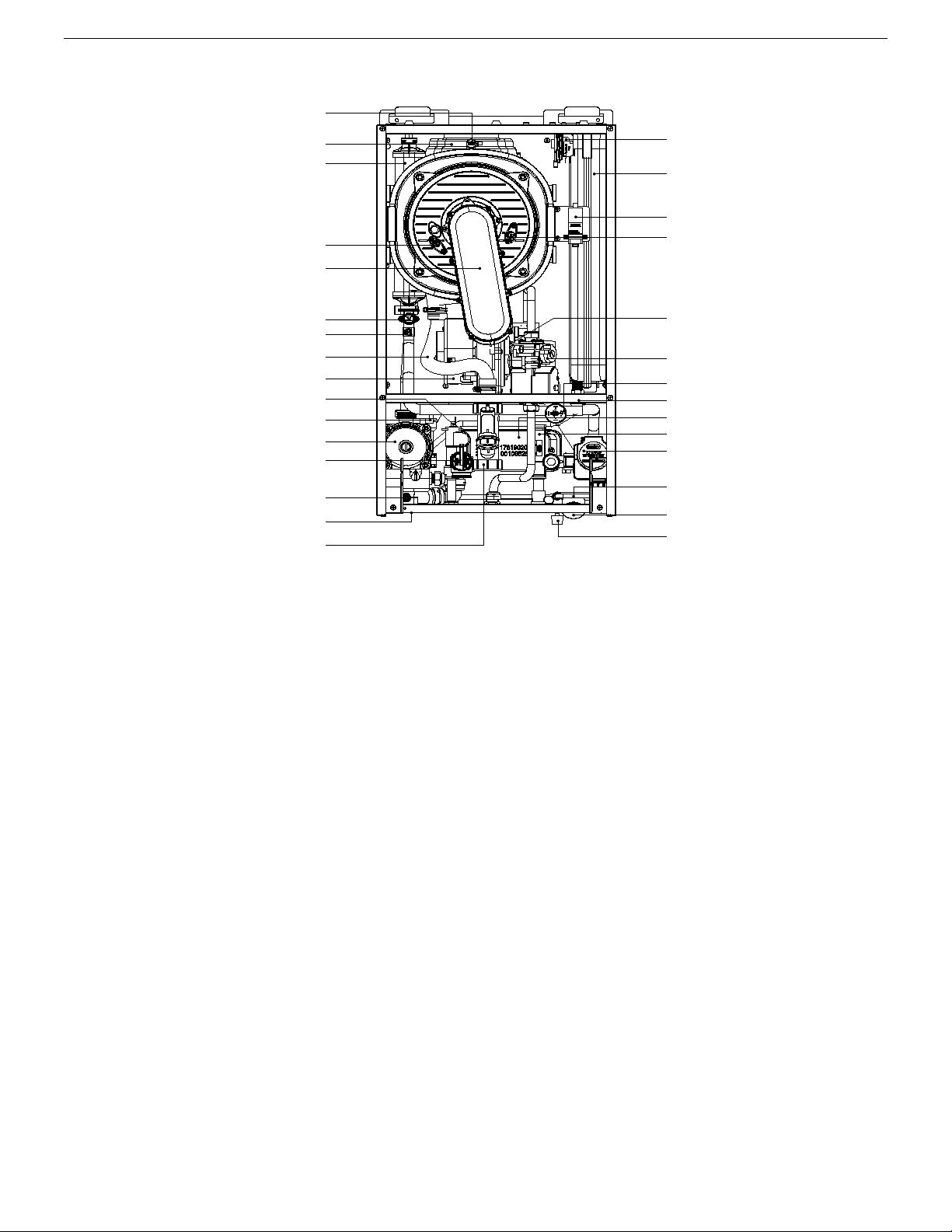
2.3 Internal parts of the water heater
LEGEND
1. PRIMARY CONDENSING HEAT EXCHANGER
2. PREMIX BURNER UNIT (GAS MANIFOLD + BURNER)
3. CONDENSATE DRAIN PIPE
4. IONIZATION ELECTRODE
5. IGNITION ELECTRODE
6. FAN
7. VENTURI
8. IGNITION TRANSFORMER
9. ELECTRONIC GAS VALVE
10. PRESSURE RELIEF VALVE
11. AUTOMATIC AIR VENT VALVE
12. HEATING SAFETY THERMOSTAT
13. HEATING SENSOR
14. PUMP WITH AIR VENT
15. WATER PRESSURE SWITCH
16. EXHAUST HOOD
17. SAFETY THERMOFUSE
18. EXPANSION TANK
19. D.H.W. SENSOR
20. CONDENSATE TRAP
21. WATER PRESSURE GAUGE
22. AUTOMATIC BY-PASS
23. AIR PRESSURE SWITCH
24. SYSTEM DRAIN VALVE
25. ROOM SEAL CHAMBER BACK SIDE
26. DIVERTER ACTUATOR VALVE
27. ELECTRONIC FLOWSWITCH
28. DHW EXCHANGER
29. HEATING LOOP FILL TAP
30. NO-RETURN VALVE
12

LEGEND
HI
HEATING INLET
HO
HEATING OUTLET
G
GAS
CWI
COLD WATER INLET
HWO
HOT WATER OUTLET
SC
CONDENSATE DRAIN
3
19
22
21
SC
23
25
18
17
2
16
19
5
4
6
9
20
11
10
24
14
15
27
29
28
13
1
12
7
30
32
26
HWO CWIG
31
8
HI HO
GENERAL INFORMATION
2.4 Water circuit
LEGEND
1. PRIMARY CONDENSING HEAT EXCHANGER
2. PREMIX BURNER UNIT (GAS
MANIFOLD+BURNER)
3. CONDENSATE DRAIN PIPE
4. IONIZATION ELECTRODE
5. IGNITION ELECTRODE
6. FAN
7. VENTURI
8. IGNITION TRANSFORMER
9. ELECTRONIC GAS VALVE
10. PRESSURE RELIEF VALVE
11. AUTOMATIC AIR VENT VALVE
12. HEATING SAFETY THERMOSTAT
13. HEATING SENSOR
14. PUMP WITH AIR VENT
15. WATER PRESSURE SWITCH
16. EXHAUST HOOD
17. SAFETY THERMO FUSE
18. EXPANSION TANK
19. D.H.W. SENSOR
20. CONDENSATE TRAP
21. WATER PRESSURE GAUGE
22. AUTOMATIC BY-PASS
23. CONDENSATE DRAIN PIPE
24. SYSTEM DRAIN VALVE
25. ROOM SEAL CHAMBER BACK SIDE
26. FLOW LIMITER
27. ELECTRONIC FLOWSWITCH
28. DHW EXCHANGER
29. DIVERTER ACTUATOR VALVE
30. HEATING LOOP FILL TAP
31. AIR PRESSURE SWITCH
32. NO-RETURN VALVE
13
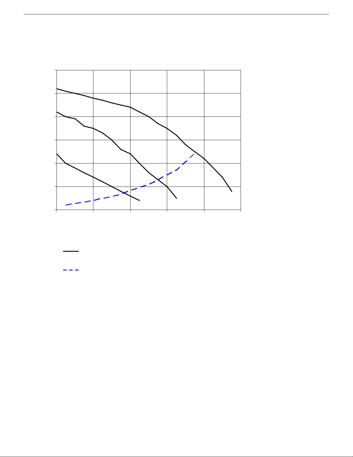
GENERAL INFORMATION
Pump head
I, II, III
Pump speed
Water heater
losses
I
II
III
0
5
10
15
20
25
30
0 2
4 6 8
10
Water flow (US gpm )
Head (ft)
2.5 Circulation pump head/flow graph
14

GENERAL INFORMATION
2.6
DIGITECH CS MIAH4 COD.40-0007
MAIN NEWS
The new electronic board Digitech CS is now installed on all condensing boiler models, from the 13kW output
model to the 100kw output model.
At the first ignition of the boiler, the function F33 (System purging function) is enable for a period of 5 minutes;
pump is enabled while the burner ignition is disable. This cycle eliminates any residual air contained in the system.
The same function is automatically enabled every time the E04 error (no water in the system) appears
display, activated by the water pressure switch, in this case for a period of 2 minutes.
Other news:
•
•
•
•
•
Here below a list of possible settings to be performed, according to the specific need, by the authorized
personnel:
•
•
•
•
With boiler in ON position, through the INFO button “i” (Info), it is now possible to display the following
information:
•
•
•
•
•
•
The chimney-sweeper function (or test function) is enabled by keeping the button "R" (Reset) pressed for 7
seconds.
on the
White backlit LCD Display;
Improved icons graphic for an easy reading and setting of the electronic board
The electronic board manages the zone control PCB from the boiler control panel (only with zone PCB
in
stalled)
The flame presence signal is completed by the power level expressed in 3 steps.
Through the INFO button “i”, with boiler in OFF position, it is possible to display the last 5 errors (to reset
press "R " button).
technical
Central heating temperature minimum and maximum set point adjustment from min 25°C to max 88°C
(factory set as 30-80°C).
Domestic Hot water temperature minimum and maximum set point adjustment from a min. 35°C to a max
75°C (factory set at 35-60°C) ;
∆t set point flow I return (only if a modulating pump and sensor on the return circuit are installed);
Minimum and maximum speed of modulating pump (if installed);
Outdoor temperature (if the outdoor temperature sensor is installed);
Kd value of outdoor temperature sensor (if installed);
Low temperature circuit temperature (if optional CRAD board for the 2 temperature circuits is
connected);
Solar panel sensor temperature (if installed);
Solar storage cylinder sensor temperature (if installed);
Fan speed.
the
15
GENERAL INFORMATION
>33% >33%<66% >66%<100%
120v 60Hz
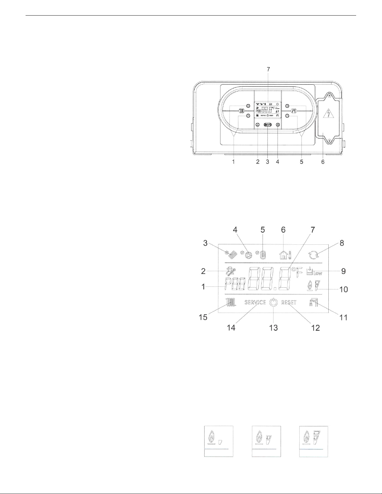
2.7 Control panel
Control panel Key
1.
HEATING TEMPERATURE SETTING BUTTONS
2.
INFO BUTTON: PRESS ONCE TO DISPLAY
TEMPERATURES AND INFO (see 2.8 INFO menu
display). KEEP INFO BUTTON PRESSED FOR 5
SECONDS (in OFF MODE) TO DISPLAY
LAST 5 ERRORS.
3.
MODE SELECTION BUTTON
WINTER ONLY I SUMMER-WINTER I OFF.
4.
RESET BUTTON:
FUNCTION ACTIVATION (CHIMNEY-SWEEPER
- KEEP IT PRESSED FOR 7 SECONDS).
5.
DOMESTIC HOT WATER TEMPERATURE
SETTING BUTTONS.
PRESSED FOR 5 SECONDS TO ACTIVATE
DISPLAY BACKLIT MODE FOR A
PERIOD OF 10 MINUTES.
6. TERMINAL BLOCK FOR EXTERNAL WIRING.
7.
LCD DISPLAY.
THE
SUMMER ONLY I
ERROR RESET - FLUE TEST
KEEP BUTTONS
'+'
AND '-'
CONTINUOUS
THE
LCD DISPLAY ICONS' KEY
1. PARAMETER NUMBER INFORMATION
2.
PARAMETERS PROGRAMMING MODE ON
3.
SOLAR PCB CONNECTION INFORMATION I
SOLAR PANEL TEMPERATURE DISPLAY (d6)
4.
SOLAR PUMP ON
5.
STORAGE CYLINDER LOW LEVEL
TEMPERATURE VISUALIZATION (d7)
CYLINDER HIGH LEVEL TEMPERATURE
VISUALIZATION (dB)
6. OUTDOOR TEMPERATURE SENSOR
CONNECTED I OUTDOOR SENSOR
TEMPERATURE DISPLAY (d2)
7.
TEMPERATURE I SET POINT I PARAMETER
VALUE INFORMATION
8.
OPEN THERM COMPONENTS COMMUNICATION
CONNECTED (REMOTE
MANAGEMENT CONTROL BOX)
9. W ATER LOW PRESSURE INFORMATION
10.
(*) FLAME PRESENCE ON (3 POWER STEPS)
11.
D.H.W. MODE ENABLED
12.
RESETTABLE ERROR DISPLAY
13.
OFF MODE
14.
NOT RESETTABLE ERROR DISPLAY
15.
HEATING MODE ENABLED
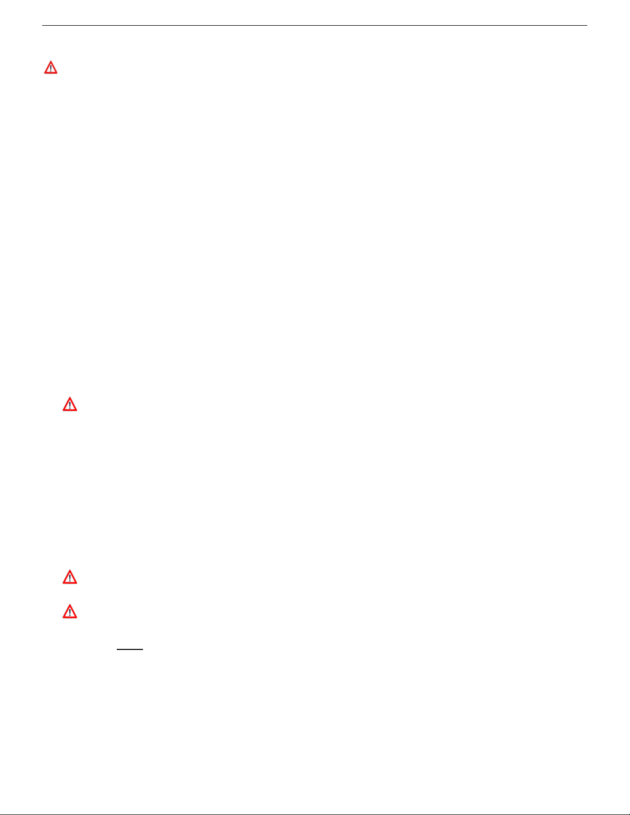
(*) -
10
can show 3 different power levels according to
the flame modulation
icon/power % images
During the boiler operation the display
I STORAGE
CONTROL I ZONE
of the boiler. (See flame
16

GENERAL INFORMATION
d00
DHW sensor temperature
d01
d02
d03
d04
d05
d06
d07
d08
INFO Menu display
Press the
Once pressed, the parameter number will appear on the left side of the display and the associated
parameter value will appear on the center of the display . Use “
temperature setting to scroll the list of available data.
“ ”
INFO button to display the boiler data.
”
and “ ” buttons of the heating
Press the
The list of available display data is the following:
Parameter Icon
“ ”
INFO button to exit the display mode.
Outdoor sensor temperature
Kd
Thermoregulation value
Fan speed
Low temperature circuit sensor (only with Zone PCB connected)
Heating return sensor temperature
Solar panel sensor temperature (only with Solar PCB connected)
Solar storage cylinder temperature (
Solar storage cylinder temperature (
Description
low level
high level
)
(only with Solar PCB
) (only w ith Solar PCB
17

GENERAL INFORMATION
3. INSTALLATION (authorized personnel)
3.1 Reference standard
Install in accordance with local building and electrical codes.
This appliance meets the requirements of:
American National Standard/CSA Standard for Gas Water Heaters Volume III, Storage Water Heaters with input
Ratings above 75,000 Btu per Hour, Circulating and Instantaneous Conforms to ANSI STD Z21.10.3, certified to CSA
STD 4.3.
Failure to install a gas appliance correctly and in accordance with the above norms could lead to prosecution. It is in
the interest of the installer and safety that the codes are complied with.
The manufacturer’s instructions form an integral part of the installation and should be left with the appliance but do not
over ride in anyway statutory obligations.
Installation requirements
Please refer to local and national standards in force with the Country of destination of the product.
18
B
C
A
Fig. 1
GENERAL INFORMATION
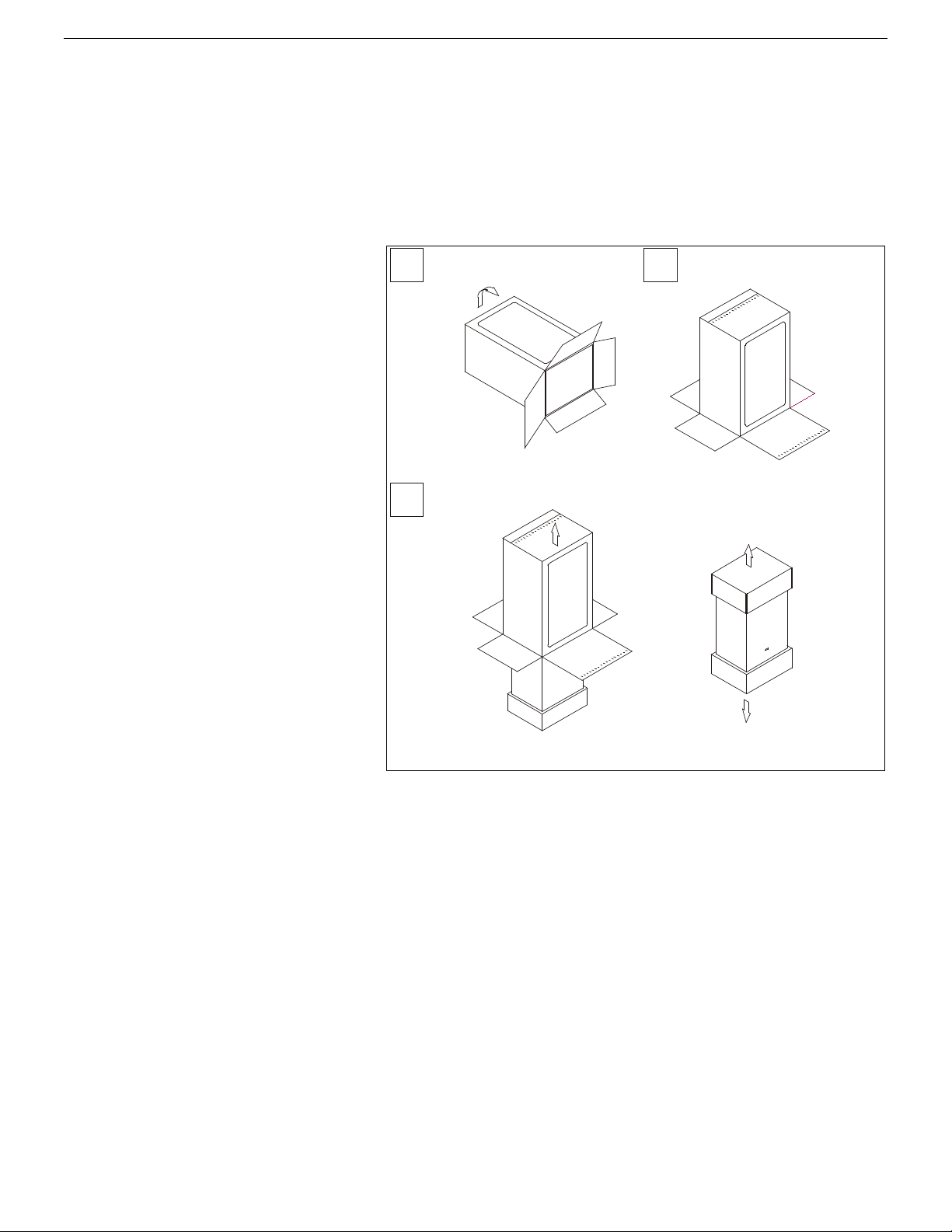
3.2 Unpacking
■ The materials (cardboard) used for packing the appliance are fully recyclable.
■ It is recommended that the packing material is only removed prior to installing the water heater. The
manufacturer will not be held responsible for damage caused by incorrect storage of the product.
■ Packing materials (plastic bags, polystyrene, nails, etc.) must not be left within reach of children, in that
these items represent a potential hazard.
A. Place the packed appliance on the
floor (see fig. 1) making sure that the
"up” arrow is facing down. Remove the
staples and open out the four flaps of the
box.
B. Rotate the water heater 180° while
manually supporting it from underneath
C. Lift the box and remove the
protections. Lift the water heater by
grasping the rear part and proceed with
the installation.
STORAGE & HANDLING
Please note that prior to installation the
FLOWMAX water heaters should be
stored in the horizontal position with no
more than three water heaters to a stack;
Ensure that the water heaters are stored
in dry conditions and be aware that the
carton is a two-man lift;
19
GENERAL INFORMATION
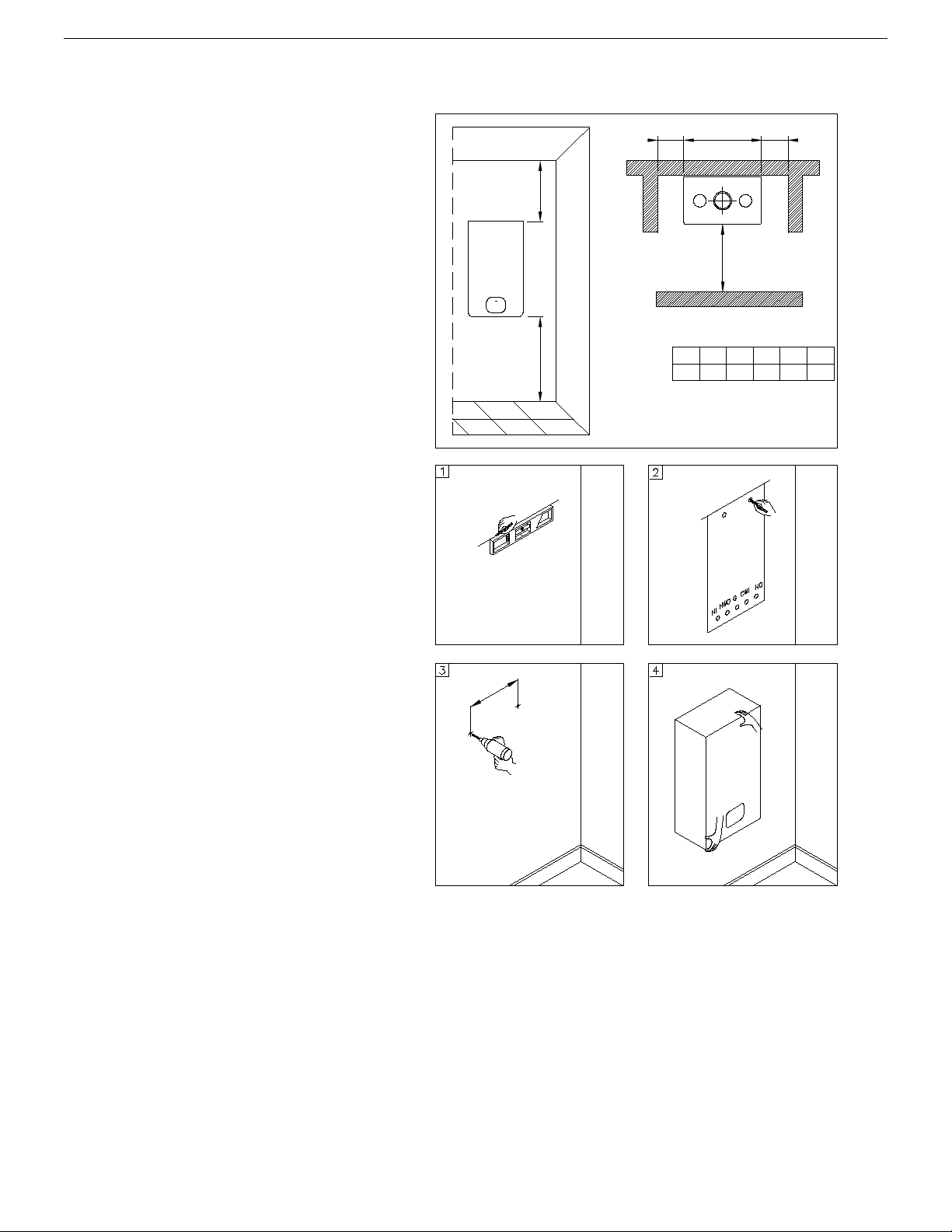
MINIMUM DISTANCES [INCHES]
H
A
X
L
Y
X Y L H
24
16
00
B
A B
18 12
FLOWMAX - 90
Model
Fig. 2
Fig. 1
3.3 Installing the water heater
■ The appliance must be installed
exclusively on a flat vertical solid wall
capable of supporting its weight.
■ The water heater should be fitted within the
building unless otherwise protected by a
suitable enclosure i.e. garage or outhouse.
(the water heater may be fitted inside a
cupboard).
■ If the water heater is sited in an unheated
enclosure then it is recommended to leave
the power on to give frost protection (frost
protection is active even with On/Off switch
in Off position).
■ If a water heater is installed in a closed water
supply system, such as one having a back
flow preventer in the cold water supply line,
means shall be provided to control thermal
expansion. Contact the water supplier or
local plumbing inspector on how to control
this situation.
In order to allow access to the interior of the
water heater for maintenance purposes, it is
important that the necessary clearances
indicated in figure 1 are respected. To make the
installation easier, the water heater is supplied
with a template to enable the pipe connections to
be positioned prior to fixing the appliance to the
wall.
To install the water heater, proceed as follows
(see fig. 2):
a. Use a spirit level (of not less than 1” long) to
mark a horizontal line on the wall where the
water heater is to be fitted.
b. Position the top of the template along the line
drawn with the level, respecting the
distances indicated. Then mark the centres
of the positions of the two wall-plugs or
anchors. Finally, mark the positions of the
water and gas pipes.
c. Remove the template and install the supplied
bracket securely to the wall. Once the
heater is securely installed, connect the
domestic hot and cold water pipes, the gas
supply pipe and the central heating pipes
using the fittings supplied with the water
heater.
d. Clearance to Combustibles
- Front : 0 inches
- Sides : 0 inches
- Rear : 0 inches
- Top : 0 inches from the jacket cover
20

1.9
3.1
4
1.2
HI
HWO G
CWI HO
4.9
2.7
3.2
LEGEND
HI
HEATING INLET
3/4" BSPP
HO
HEATING OUTLET
3/4" BSPP
G
GAS
1/2" NPT
CWI
COLD WATER INLET
1/2" BSPP
HWO
HOT WATER OUTLET
1/2" BSPP
Fig. 1
3.4 Water connections
In order to safeguard the heat exchanger
and circulation pump, especially in case
of water heater replacement, it is
recommended that the system is hotflushed to remove any impurities
(especially oil and grease) from the
pipes and radiators.
Make sure that the domestic water and
central heating pipes are not used to
ground the electrical system. The pipes
are totally unsuitable for this purpose.
Isolation Valves must be installed on the
heating and D.H.W circuits. This will
facilitate all maintenance and service
operations where the hot water needs to
be drained.
Water connection tail pieces / unions are
supplied with every unit and must be
used. These are the only fittings that
must be installed on to the unit. They are
designed to be tightened on to the
appropriate male thread along with the
fiber washer.
GENERAL INFORMATION
Failure to use these tail pieces will cause
the unit to leak and will VOID the
warranty.
To prevent vibration and noise coming from the system the system, do not use pipes of reduced diameter,
short radius elbows or severe reductions in the cross sections of the water passages.
In order to guarantee the reliability of the water heater and prevent permanent damage in areas with high water
inlet pressure too, a 30 psi (2 bar) pressure reducing valve should be fitted.
The water flowing out of the pressure/relief valve during its operation may be extremely hot. Before operating relief
valve, make sure drain line is installed to direct discharge to a safe location such as an open drain. Avoid scalding
and/or water damage.
A pressure relief valve is installed in this dual purpose water heater that is rated in accordance with and complying with
either The Standard for relief Valves and Automatic Shutoff Devices for Hot Water Supply Systems, ANSI Z21.22 CSA
4.4 Code.
The relief valve must be installed such that the discharge will be conducted to a suitable place for disposal when relief
occurs and that no reducing coupling or other restriction be installed in the discharge line. The discharge line must be
installed to allow complete drainage of both the valve and the line. If this unit is installed with a separate storage
vessel, the separate vessel must have its own temperature and pressure relief valve. No valve is to be placed between
the relief valve and the tank. This valve must also comply with The Standard for Relief Valves and Automatic Shutoff
Devices for Hot Water Supply Systems. ANSI Z21.22 or CSA 4.4. If a relief valve discharges periodically, this may be
due to thermal expansion in a closed water system. Contact the water supplier or local plumbing inspector on how to
correct this situation. Do not unplug relief valve.
21
GENERAL INFORMATION
3.5 Domestic hot water circuit/Condensate Drain
Warning/ Hard Water
If this water heater is installed in an application where the supply water is hard, it must be treated with either a
water softener and filtration, which removes the hardness or by using sequestering agents that reduce the
amount of scale deposits.
Damage to the water heater as a result of water in excess of 14.5 gpg (250mg/L) of hardness is not covered by
FLOWMAX Limited warranty. If there a problem with the water quality, contact your local water conditioning
company for equipment to condition the water supply to this appliance
The cold water supply pressure at the inlet to the water heater must be between 7.25 psi (0.5 bar) and 87 psi (6
bar).
In areas with higher water inlet pressure a pressure reducing valve must be fitted before the water heater.
The frequency of the heat exchanger coil cleaning depends on the hardness of the mains water supply and the
presence of residual solids or impurities, which are often present in the case of a new installation. If the characteristics
of the mains water supply are such that require it to be treated, then the appropriate treatment devices must be
installed, while in the case of residues, an in-line filter should be sufficient.
Central heating circuit
In order to prevent scaling or deposits in the primary heat exchanger, the mains supply water to the heating circuit
must be treated according to the requirements of local standards.
This treatment is indispensable in the case where the circuit is frequently topped-up or when the system is often either
partially or fully drained.
Condensate Drain
■ FLOWMAX water heater is a high efficient gas appliance that creates condensation when it operates. A
condensate trap and flexible drain pipe comes factory installed inside each water tank.
The condensate trap must be primed before operation to prevent exhaust gases from entering the building.
■ Follow your local code with regards to the disposal of condensation
■ Here are several options for disposal of condensate
o From combination water heater direct to drain
o From combination water heater to neutralizer to drain
o From combination water heater to laundry tub (bottom of water heater must be above the height of the
laundry tub; must have a negative slope to properly drain)
o From combination water heater to condensate pump to laundry tub (for long distances between water
heater and laundry tub or when bottom of the water heater is installed below height of the laundry tub)
■ Failure to install the condensate discharge properly will affect the reliability of the water heater.
For all units installed with vertical exhaust, must have an additional approved condensate drain. Fittings must
be ULC S636 approved.
Failure to properly connect the condensate line will cause combustion gases to enter the room, possibly
causing serious injury to occupants or death.
Note: Check with your municipality, local codes, or local gas company to determine if disposal of
combustion condensate is permitted. In the State of Massachusetts the condensate must be
neutralized prior to entering a drain
■ Use only PVC, vinyl or CPVC pipe for the condensate drain line, metal pipe work is not suitable for condensate
discharge system.
The condensate drain line should be a minimum of 1/2” diameter that connects to the 7/8” supplied hose and must be
supported to prevent sagging. Manufacturer will supply a ¾” to ½” reducer for connection.
22

GENERAL INFORMATION
■ Keep the length of the condensate drain as short as possible. Long runs or applications where the nearest
drain is above the water heater will require the use of a condensate pump. Size the pump to allow for a
maximum condensate discharge of 2 gpm from the water heater. The end drain pipe must not be submerged in
water or blocked in any way.
■ The condensate pump must be installed with an overflow safety switch that detects downstream clogs and
shuts off the water heater before flooding occurs. See condensate pump manufacture for installation
instructions.
■ Be sure to check that condensate is freely flowing from the drain piping after the system has been installed.
Condensate will begin flowing out of the water heater within 15 minutes after operation has started.
■ Do not run condensate line outside and take measures to prevent the condensate drain lines from freezing
(insulation, heat tape, electric heaters, etc.)
■ Be sure to clean the condensate trap at least once per year to prevent any problems, and after cleaning be
sure to check for any leaks of condensed water or flue gas.
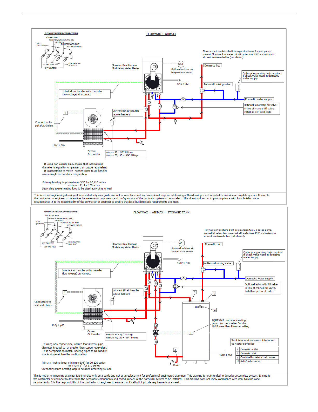
Space Heating
Suitable for combination water (potable) heating and space heating and not suitable for space heating
applications only.
Piping and components connected to the water heater for the space heating application shall be suitable for
use with potable water.
Toxic chemicals used for water heater treatment shall not be introduced into the potable water.
A water heater which will be used to supply potable water shall not be connected to any heating system of
component(s) previously used with nonpotable water heating appliance.
When the system requires water for the space heating at temperatures higher than required for other uses, a
means such as a mixing valve shall be installed to temper the water for those uses in order to reduce scald
hazard potential.
The water heater can be used for potable hot water heating and combination space heating applications.
Note: the following illustrations are conceptual designs only. There are many design variations of the equipment
presented. Designers must add all necessary safety and auxiliary equipment to conform to Code requirement and
proper design practice. For more details, contact the manufacturer or distributors of the products.
23
GENERAL INFORMATION
3.6 Schematic of Piping Installation
24

GENERAL INFORMATION
25

GENERAL INFORMATION
3.7 Gas Connection
3.7.1 Gas Piping Guidelines
Follow all local codes and/or the most recent edition of the National Fuel Gas Code (ANSI Z223.1/NFPA 54) in the
USA or the Natural Gas and Propane Installation Code in Canada (CAN/CSA B149.1).
3.7.2 Gas Supply Lines Pressures
The minimum and maximum inlet gas pressures are Natural Gas Min. 7.00”WC – Max. 14.00”WC.
Gas pressures over and above the specified range will result in adverse performance and dangerous operating
conditions; any damage resulting from extreme gas supply pressures will not be covered by the limited warranty.
Until pressure testing of the main gas supply line is completed, ensure the gas line to the FLOWMAX Combination
Water Heater is disconnected to avoid any damage to the water heater.
The appliance and its individual shut off valve must be disconnected from the gas supply piping system during any
pressure testing of that system at test pressures in excess of 0.5 psi (3.5 kPa)..
The appliance must be isolated from the gas supply piping system by closing its individual manual shut-off valve
during any pressure testing of the gas supply system at test pressures equal to or less that 0.5 psi (3.5 kPa).
The gas appliance and its gas connections must be leak tested before placing the appliance in operation. Leaks
can be found by using a gas leak detection device or by applying soapy water to all gas fittings. Should bubbles
occur, tighten those connections and re-test.
Always purge the gas line for any debris before connecting to the water heater gas inlet.
Never use an open flame to test for gas leaks as property damage, personal injury or death could result.
The maximum inlet gas pressure must not exceed the valve specified by the manufacturer and that the minimum
valve listed as for the purposes of input adjustment.
The connection to the gas supply must be carried out by professionally qualified personnel in accordance with the
relevant standards.
■ Check the internal and external seals of the gas supply system.
■ A gas shut-off valve must be installed upstream of the appliance
■ Before starting up the water heater, make sure that the type of gas corresponds to that for which the appliance has
been set-up.
■ The gas supply pressure must be between the values reported on the rating plate.
■ Conversion of the appliance from natural gas to LPG or vice versa must be carried out by qualified personnel.
■ The power supply cable must be replaced by a qualified electrician. If the cable is damaged in any way, switch off
the appliance and have the cable replaced by a suitably qualified electrician.
When using an electrical appliance, a few fundamental rules must be observed:
• Do not touch the appliance with damp or wet parts of the body or when barefoot.
• Do not pull on the electric wires.
Do not allow the appliance to be used by children or anyone unfamiliar with its operation.
26

GENERAL INFORMATION
3.8 Electrical connections
3.8.1 General warnings
Follow the electrical code requirements of the local authority having jurisdiction. In the absence of such
requirements, follow the latest edition of the National Electrical Code (NFPA 70) in the U.S. or the latest edition of
CGA C22.1 Canadian Electrical Code – Part 1 in Canada.
3.8.2 Electric Wiring: Ground and Surges
All units come with factory installed 3-pronged (grounded) plug end. The combination water heater can be
plugged into any standard electrical duplex outlet close to the unit as it requires only 4 Amps.
If the local jurisdiction requires the unit to be wired directly, remove and discard the factory installed plug. An
ON/OFF switch controlling the main power between the breaker and the FLOWMAX Water Heater should be
provided to facilitate end-user maintenance and servicing. This should be done by a qualified electrician.
The combination water heater must be electrically grounded. Ensure the electrical receptacle, in which the water
heater will be plugged into, is properly grounded; if wiring directly, do not attach the ground wire to either the gas
or the water piping as plastic pipe or dielectric unions may isolate the water heater electrically.
The use of a surge protector is recommended to protect from power surges.
Do not energize electric power to the unit until all plumbing and gas piping is complete and the combination water
heater has been filled with water.
The electrical supply required by the water heater is 120VAC at 60Hz with a maximum 4A rating with proper
grounding.
DO NOT connect 220-240VAC and any other voltage to this FLOWMAX Combination Water Heater. This will
damage the combination water heater and void the warranty.
Do not disconnect the power supply when the unit is in normal operation.
If there is a power failure in cold weather areas, the freeze prevention system in the water heater will not operate
and may result in freezing of the heat exchanger; in cold weather areas where power failures are common, you
must completely drain the unit to prevent damage if the power will be off for any extended period of time.
Damage caused by freezing is not covered under warranty.
CAUTION : Label all wires prior to disconnection when servicing controls. Wiring errors can cause improper and
dangerous operation. Verify proper operation after servicing.
The connection to the main power supply must be carried out by professionally qualified electrical personnel,
registered in accordance with current legislation and local authorities.
Always check to make sure that the appliance has an efficient ground system. This requirement is only satisfied if
it has been properly connected to an efficient ground system installed in accordance with the requirements of
current safety standards and carried out by professionally qualified personnel.
This basic safety measure must be checked, verified and carried out by professionally qualified personnel.
Have the electrical system checked by a qualified electrician. The manufacturer will not be held liable for any
damage or injury caused as a result of an inefficient or faulty ground system.
27

GENERAL INFORMATION
■ Ensure the domestic power supply is checked by a qualified electrician to ensure that it can support the maximum
power absorption of the appliance, as indicated on the rating plate. In particular, make sure that the cable sizes are
adequate for the power absorbed by the appliance;
■ The power supply cable must be replaced by a qualified electrician. If the cable is damaged in any way, switch off
the appliance and have the cable replaced by a suitably qualified electrician;
When using an electrical appliance, a few fundamental rules must be observed:
• Do not touch the appliance with damp or wet parts of the body or when barefoot.
• Do not pull on the electric wires.
• Do not allow the appliance to be used by children or anyone unfamiliar with its operation;
If the unit fails to re-start after any fault, unplug the unit for 30 seconds, then re-plug in the unit and try to restart with the on/off
switch. If the unit fails to restart, call a qualified Technician for service.
28

GENERAL INFORMATION
3.8.3 Remote control connection
Electrical connections (Option)
Connect the power supply to the terminal board located onto the control panel as
follows:
a.
switch off the power supply at the main switch;
b.
remove the front case panel of the boiler.(see paragraph '6.3 Accessing the boiler');
c.
Slacken the screws and remove plate A from the control panel (see fig. 1). With the plate removed, proceed
with the following wires connection:
•
of the outdoor temperature sensor on contacts marked as Se·Se on the terminal board "B";
• remove jumper from Ta –Ta from the terminal board B and install the control field supplied control wire
leading to a heating dry contact
d.
When wires have been connected, place plate "A" back to position and then the front case panel.
In case of a simultaneously outdoor temperature sensor and remote control installation, the printed circuit board
sends the outdoor temperature value to the remote control only, without using it for the modulation. The
communication between the printed circuit board and the remote control happens separately from the boiler
functioning mode selected and, once the connection has been established, the user interface on board is disabled
and displayed by the symbol
.
29

GENERAL INFORMATION
3.9 Venting
Improper venting of combination water heater can result in excessive levels of carbon monoxide, which
can result in severe personal injury or death. This combination water heater must be vented in
accordance with the “Venting of Equipment” section of the latest edition of the ANSI Z223.1 / NFPA 54
Natural Gas Code and/or the “Venting systems and air supply for appliances” section of the latest version
of the CAN/CSA B149.1 Natural Gas and Propane Installation Code in Canada and in accordance with all
applicable local building codes.
Venting Guidelines
• For best results, keep the vent system as short and straight as possible.
• Locate the combination water heater as close as possible to the vent termination.
• This combination water heater vent must not be common vented with any other gas appliance or vent stack.
Slope v
•
• V
• Vent and air intake pipe must be supported every 4 feet of horizontal run and every 5 feet of vertical run.
FLOWMAX and Direct Vent
ent upwards towards the vent terminal at a minimum rate of 1/8” per foot (1% slope).
ent termination must be a minimum of 12” above grade or expected snowfall.
• All FLOWMAX Combination Water Heaters are prepared at the factory to be direct vent (sealed combustion)
units which draw all of their required combustible air directly from outside the building.
• All FLOWMAX Combination Water Heaters use 2” or 3” diameter exhaust and 2” or 3” diameter air intake pipe.
• The air intake vent materials can be made of ABS, CPVC, PVC materials and in accordance with all applicable
local building codes. .
Contaminated Make-Up Air Will Damage the Unit
• Recommend not to operate the combination water heater in an area that is or will be under construction or
renovation.
• The FLOWMAX warranty will not cover damage and premature wear caused to the unit due to installation in a
contaminated environment.
• All of the exhaust venting connections must be leak checked with a soap solution upon initial start up of the
water heater. Any leaks must be repaired before continuing operation of the water heater.
• Warranty will not be available if the water heater is used for construction heat.
E
xhaust Vent Piping Materials
• Use only 2” or 3” solid PVC/CPVC schedule 40 PVC/CPVC or ULC S636 pipe and fittings
enting requirements in USA and Canada are different. Please consult with the most recent edition of the
• V
National Fuel Gas Code (ANSI Z223.1 / NFPA 54) or CAN/CSA B-149.1 as well as local codes for applicable
venting regulations and restrictions.
.
• For installation in Canada, field supplied plastic vent piping must comply with CAN/CSA B-149.1 (latest edition)
and be certified to the standard for type BH Gas Venting Systems, ULC S636 components of this listed system
shall not be interchanged with other vent systems or unlisted pipe/fittings. All plastic components and specified
primers and glues of the certified vent system must be from a single manufacturer and not intermixed with
other system manufacturer’s vent system parts. The supplied vent adaptors are certified as part of the
combination water heater.
• For all units installed with vertical exhaust, must have an additional approved condensate drain installed on t
orizontal section of the exhaust vent. Fittings must be ULC S636 approved.
H
• PVC/CPVC pipe/fittings have been approved for use on this appliance with zero clearance to combustibles.
30
he

GENERAL INFORMATION
Model
Size
Max Equivalent
Vent Run
Type
Exhaust Vent
Intake Vent
FLOWMAX-90
2"/ 3" Diam
100 ft
Natural Gas or LP
Schedule 40 PVC/CPVC
PVC, CPVC or ABS
FLOWMAX-120
3” / 4"" Diam
100 ft
Natural Gas or LP
Schedule 40 PVC/CPVC
PVC, CPVC or ABS
FLOWMAX-170
3" Diam
100ft
Natural Gas or LP
Schedule 40 PVC/CPVC
PVC, CPVC or ABS
• This water requires a special venting system. Refer to the installation instructions for parts list and method of
installation.
• Use of cellular core PVC (ASTM F891), cellular core CPVC, or Radel (polyphenylsulfone) in non-metallic
venting systems is prohibitted. Covering non-metallic vent pipe and fittings with thermal insualtion is
prohibitted.
I
ntake Vent Pipe Materials
PVC, CPVC or ULC S636 pipe and fittings and ABS pipe and fittings can be used for combustion air intake on
FLOWMAX products.
• Transition cement must be used if ABS pipe is connected to the PVC appliance adaptors.
• All plastic components and specified primers and glues of the certified vent system must be from a single
manufacturer and not intermixed with other system manufacturers vent system parts.
• The vent for this appliance shall not terminate over public walkways, near soffit vents, crawl spaces or other
areas where condensate or vapour could create a nuisance or hazard or cause property damage or wher
c
ondensate vapour could cause damage or could be detrimental to the operation of regulators, relief valves of
other equipment.
e
A
llowable Vent Lengths
Length Vertical
and Horizontal per
E
quivalent Lengths
• Reduce the maximum vent length accordingly for each elbow used.
• Each 2”/3” 45⁰ elbow equates to 2.5 linear feet of vent pipe.
• Each 2”/3” 90⁰ short radius elbow equates to 7.5 linear feet of vent pipe.
• Each 2”/3” 90⁰ long radius elbow equates to 5 linear feet of vent pipe.
• The maximum length listed is for exhaust vent only. The intake length should be equal length.
• The total maximum equivalent vent pipe distance cannot exceed 100ft for horizontal and vertical venti
stance.
di
• The maximum lengths are not including elbows.
ng
• Exceeding the maximum venting distances will cause the appliance to malfunction or cause an unsafe
M
inimum Vent Lengths
• 2" Diameter - 12" pipe (Iength) plus one elbow.
• 3" Diameter - 16" pipe (Iength) plus one elbow.
condition.
31

REGULATION INSTRUCTIONS
32

REGULATION INSTRUCTIONS
33

REGULATION INSTRUCTIONS
34

REGULATION INSTRUCTIONS
35

REGULATION INSTRUCTIONS
36

REGULATION INSTRUCTIONS
4. COMMISSIONING THE APPLIANCE
4.1 General warnings
The following operations must be carried out by professionally qualified personnel, registered in
accordance with current legislation.
The water heater leaves the factory pre-set and tested for burning either natural Gas or LPG.
Nevertheless, when starting the water heater for the first time, make sure that the information on the
rating plate corresponds to the type of gas being supplied to the water heater.
Once the system has been filled and the necessary adjustments made, remember to tighten the screws of
the gas valve test point and make sure that there are no gas leaks from the test point and from any pipe
fittings upstream of the gas valve.
■ Preliminary operations
Switching the water heater on for the first time means checking that the installation, regulation and operation of the
appliance are correct:
• Check that the rating on the rating plate corresponds to that of the mains supply networks (gas, electricity, water));
• Check that the power supply voltage to the water heater complies with the rating plate (120 V – 60 Hz) and that the
live, neutral and ground wires are connected properly. Also make sure that the ground connection is sound;
• Check that the gas supply is correctly sized for the flow rate required by the water heater and that it is fitted with all
the safety and control devices stipulated by current regulations;
• Check that the supply of combustion air and exhaust and condensate discharge systems are functioning correctly
and in line with current law and national and local standards;
• Check for the presence of permanent aeration/ventilation openings as required by current law for the type of
appliances installed;
• Check that the exhaust vent and its connections to the termination comply with the requirements of current law and
national and local standards for the type of appliances installed;
• Check that the condensate drain system, including outside the water heater (exhaust system condensate collection
devices), allows the condensate to flow freely to the drain.
• Check that there are no flammable materials or liquids in the immediate vicinity of the water heater;
• Flush out both primary and domestic hot water circuits (see 4.3 “Flushing the system”).
37

REGULATION INSTRUCTIONS
4.2 Filling the system
Check the properties of the water supply and install the
appropriate treatment devices if the mains water has a
hardness rating more than 14.5 gpg (250 mg/L) i
prevent scaling and eventual damage to the D.H.W heat
exchanger.
Use only clean tap water to fill the system.
A pre-filtering system can be installed on the incoming water
supply to help reduce impurities and limestone.
This water heater must have adequate water flowing through it
whenever the burner is on. Failure to do this will damage the
unit and void the warranty.
Once the water pipes have been connected, close the gas feed valve and fill the system as follows:
n order to
• Check that the circulation pump runs freely;
• Check that the plug of the air vent valve has been slackened slightly
to allow air to escape from the system (fig.1);
• Open the main domestic water supply valve;
• Open the filling tap R (fig. 2);
• Unscrew the plug on the pump to remove any trapped air, check that
the pump is free then re-tighten it when water starts to flow out
(fig.1);
• Before switching on the water heater, purge air completely from
the air vent valve positioned on the top of the condensing
exchanger (fig. 3);
• Open the air vents on the radiators and monitor the air evacuation
process. When water starts to flow out of the radiators, close the air
vents;
• Use the pressure gauge M (fig. 2), to check that the systems
pressure reaches the middle of the green area (equal to 1,2 bar, see
fig. 4).
• On completion, make sure that the filling tap R is perfectly
closed.
38

REGULATION INSTRUCTIONS
T
S
Fig. 1
4.3 Flushing the system
Failure to flush and add inhibitor to the system will invalidate the appliance operation.
All systems must be thoroughly drained and flushed out using additives – corrosion inhibitors and flushing
agents/descalers. All flushing must be done for new and retrofit installs.
Warning: Failure to clean the system and add adequate inhibitor invalidates the warranty.
To flush out the primary side of this unit
a. Fill the water heater with clean water as per the filling instructions.
b. Using a drain off cock on the lowest point of the system allow the water to drain from the system and water heater.
c. In order to flush the system correctly, turn off all radiators or fan coils. Open the filling loop and drain cock
simultaneously and allow the water to flow through the water heater.
d. Open each individual radiator or fan coil, allowing water to flow through. Then turn that radiator or fan coil off
epeat for all radiators or fan coils on the system.
r
e. Turn off the filling loop and close the drain cock. Open all radiators or fan coils and open the filling to fill the
s
ystem.
f. Continue to fill the system until the pressure gauge reaches 14.5 psi (1 bar).
g. Add an inhibitor to the system water to prevent limestone and magnetite deposits from forming and to protect t
ater heater from galvanic corrosion.
w
h. In areas where freezing might occur, an antifreeze (Gycol) may be added to the system water to protect the
system. Please adhere to the specifications given by the antifreeze manufacture. Do not use automotive silicate
based antifreeze. Please observe that the antifreeze and water mixture does not exceed 40% of the antifreeze
content. Do not use antifreeze other than that specifically made for hot water heating systems. Advise systems
operator/ultimate owner that system is filled with antifreeze.
and
he
To flush out domestic hot water circuit
a. Open all hot water outlets.
b. Turn on inlet group supply so water enters the water heater; leave to fill until water is released from the hot water
outlets. Turn off all hot water outlets.
c. Connect a hosepipe to the cylinder drain cock and open the drain cock.
d. Allow water to flow through the water heater and out of the drain cock.
e. Turn off water supply, disconnect the hosepipe, close the drain cock and refill the water heater.
f.
4.4 Filling the condensate trap
he condensation trap must be pre-filled when starting the water heater for the first time in order to prevent flue gases
T
from flowing back through the trap.
The filling operation is carried out as follows (see
fig. 1):
• Remove plug T and fill the trap S three quarters
full with water;
• Replace plug T and connect the drainpipe P
into a condensate discharge trap conforming to
current legislation;
ttention! It is recommended to clean the
A
condensate trap, after a few months of water heater
operation, to remove deposits/residuals left after
the first condensate passage within the water
heater new components that may interfere with the
correct operation of the trap itself.
39

REGULATION INSTRUCTIONS
Table n°1
Gas type
CO2 %
Natural Gas - G20
9.4
Liquid Propane Gas - G 31
10.96
V
Fig. 1
4.5 Starting up the water heater
Once the system has been filled, proceed as
follows:
• Check that the exhaust vent is free of
obstructions and correctly connected to the
water heater;
• Switch on the power supply to the water
heater;
• Open the gas isolation valve;
• Place switch 1 in the ON position (see 2.7
“Control Panel”), after a few seconds the
circulating pump will start to run;
• Use button 6 to set the SUMMER, WINTER or
SUMMER/WINTER function. The symbols
will light up (fixed light) to indicate that
the water heater is working;
• The automatic ignition system will then light
the burner. This operation is repeated for
times. It may however be necessary to repeat
the operation in order to eliminate all the air
from the pipes. To repeat the operation, wait
approximately three minutes before reattempting to light the water heater. To reset
the water heater Switch off switch 1 (see 2.
Control Panel”) and switch it back on again
“
and repeat the lighting procedure;
• With the water heater ignited, if the system still
emits noises, the operations must be repeated
until all the air has been removed;
• Check the pressure in the system. If t
essure has fallen, re-open the filling tap until
pr
the code H2O disappears on the display and
the pressure reaches the middle of the green
area (1,2 bar). On completion, close the
filling tap.
• If the CO2 value does not correspond to the
specified value, adjust screw V (see fig. 1) on
the venture clockwise to reduce the CO2 value
or anticlockwise to increase it
;
3
he
7
•
The combustion air and vent adapters with 1/2"
test ports and plugs may be equipped in any
orientation on units to allow easier access when
preforming combustion analysis and other
testing (Fig. 2).
40

REGULATION INSTRUCTIONS
PARAMETER
No
TYPE OF OPERATION
PARAMETER
VAL UE
FUNCTION
00 (do not use)
06 (do not use)
00 - 13 KW
06 - 100 KW
00 (do not use)
05 (do not use)
00 – Instantaneous w/ dual circuit Exchanger
05 - Only Heating Boiler
P02
Selects the type of gas supplied
00 - 01
02 (do not use)
00 - Natural Gas - 01 - LP Gas
02 - G25
P03
Sets the central heating temperature
00 - 01
Standard (30 - 80°C) - Reduced (25 - 45°C)
00
04
0 Seconds (Disabled)
400 Seconds
P05
Water hammer prevention function
00 - 01
Off - On
P06
DHW Priority Function
00 - 01
Off - On
P07
Central Heating Timer
00 - 90
Displayed in multiples of 5 seconds
(Default value 36 x 5 = 180”)
P08
Central heating Pump Overrun Timer
00 - 90
Displayed in multiples of 5 seconds
P09
DHW / Storage Cylinder Pump Overrun
Timer
00 - 90
Displayed in multiples of 5 seconds
(Default value 18 x 5 = 90”)
P10
Sets the Minimum Fan Speed
(displayed in Hertz)
66 Ng / 60 Lp
60 Ng / 60 Lp
Flowmax 90
Flowmax 170
P11
Sets the Maximum Fan Speed
(displayed in Hertz)
162 Ng / 149 Lp
155 Ng / 143 Lp
Flowmax 90
Flowmax 170
P12
Sets the Minimum Fan Speed
(displayed in Hertz)
66 Ng / 60 Lp
60 Ng / 60 Lp
Flowmax 90
Flowmax 170
P13
Sets the Maximum Fan Speed
(displayed in Hertz)
162 Ng / 149 Lp
155 Ng / 143 Lp
Flowmax 90
Flowmax 170
(displayed in Hertz)
90 Ng / 110 Lp
90 Ng / 110 Lp
Flowmax 90
Flowmax 170
P15
Legionella prevention Function
(For storage boilers only)
00 - 01
Off - On
P16
Sets the climatic compensation curve
(w/outdoor temperature sensor only)
00 - 30
See the graph in the parameter setting explanation
P17
Sets the temperature measurement units
00 - 01
°C - °F
00
02
Disabled
Burner output control mode
P19
Central heating minimum set point
20 – 40
Displayed in °C
P20
Central heating maximum set point
40 – 88
Displayed in °C
P21
DHW maximum set point
45 – 75
Displayed in °C
P22
∆T set point T° flow / T° return
sensor connected only)
00
Disabled
P23
Modulating pump minimum speed
sensor connected only)
P24
Modulating pump maximum speed
sensor connected only)
70 – 100
Displayed in percentage
P25
∆T timing T° flow / T° return
sensor connected only)
20 – 100
Displayed in seconds
5. REGULATING THE APPLIANCE - NORDGAS
P00
P01
P04
Selects the model of boiler
Selects the type of boiler
Heating output rising time
(Domestic Mode)
01 (do not use)
02
03 (do not use)
04
05
01
02
03
(do not use)
04
01
02
03
55 Ng / 52 Lp
01 - 18 KW
02 – Flowmax 90
03 - 28 KW
04 – Flowmax 120
05 – Flowmax 170
01 - Instantaneous w/ secondary DHW Plate exchanger
02 - Storage Cylinder Boiler
03 - Boiler w comfort storage cylinder
04 - Instantaneous Comfort Mode w/ preheat function
50 Seconds (Default)
100 Seconds
200 Seconds
(Default value 36 x 5 = 180”)
Flowmax 120
P14
P18
(Domestic Mode)
(Central Heating Mode)
(Central Heating Mode)
Sets the Ignition Sequence
Sets the 0-10v industrial bus piloting
(w/modulating pump and return temperature
(w/modulating pump and return temperature
(w/modulating pump and return temperature
(w/modulating pump and return temperature
164 Ng / 155 Lp
55 Ng / 52 Lp
164 Ng / 155 Lp
110 Ng / 130 Lp
01
10 - 40
50 – 70
Flowmax 120
Flowmax 120
Flowmax 120
Flowmax 120
Flow temperature Control mode
Displayed in °C
Displayed in percentage
NOTES:
P04
This parameter allows to modify the time the boiler takes (in heating mode) to reach the maximum power set.
P10, P11, & P12
P13
The maximum boiler power in heating mode, can be set according to the paragraph 5.5 "Heating output (Kw) - Fan frequency (Hz) diagram".
These parameters are automatically set according to the output value set in Parameter P00.
41

REGULATION INSTRUCTIONS
Accessing the parameters menu
To modify the preset values of the parameters reported in the previous table, open the parameter settings menu as
follows:
1. Place mode selection button “ ” in OFF position,
visualized by
2. Keep pressed ' ' and ' ” buttons simultaneously and
wait for
3. Release buttons '
4. Use ' ' and “ ” buttons of heating temperature
setting
Adjust the value of the parameter using the procedure described in the following pages.
symbol and 'P00', to appear on the display.
to select the parameter to modify;
symbol;
‘ and ‘ ”:,
42

5.2 Setting the parameters
PARAMETER P00 – SELECTS THE MODEL OF BOILER
To enter the parameters menu, follow the previously described procedure (see
paragraph 5.2 ‘Accessing the parameters menu’ - steps 1-4).
REGULATION INSTRUCTIONS
5. Use
value of the parameter:
00 = (do not use)
01 = (do not use)
02 = Flowmax 90
03 = (do not use)
04 = Flowmax 120
05 = Flowmax 170
06 = (do not use)
6. Press mode selection button
parameter operative.
7. To exit from the parameters menu, press simultaneously
buttons.
and buttons (D.H.W temperature setting) to modify the
to confirm and to render the new
and
PARAMETER P01 – SELECTS THE TYPE OF BOILER
To enter the parameters menu, follow the previously described
procedure (see paragraph 5.2 ‘Accessing the parameters menu’ steps 1-4).
5. Use
value of the parameter:
00 = (do not use)
01 = Instantaneous w/ secondary DHW Plate exchanger
02 = storage cylinder boiler
03 = (do not use)
04 = Instantaneous Comfort Mode w/ preheat function
05= (do not use)
and buttons (D.H.W temperature setting) to modify the
6. Press mode selection button
parameter operative.
7. To exit from the parameters menu, press simultaneously
buttons.
to confirm and to render the new
and
PARAMETER P02 – SELECTS THE TYPE OF GAS SUPPLY
To enter the parameters menu, follow the previously described
procedure (see paragraph 5.2 ‘Accessing the parameters menu’ steps 1-4).
5. Use
value of the parameter:
00 = Natural Gas
01 = LPG
02 = G25 (do not use)
6. Press mode selection button to confirm and to render the new
parameter operative.
7. To exit from the parameters menu, press simultaneously
buttons.
and buttons (D.H.W temperature setting) to modify the
and
43

REGULATION INSTRUCTIONS
PARAMETER P03 – SETS THE CENTRAL HEATING
TEMPERATURE
To enter the parameters menu, follow the previously described procedure (see
paragraph 5.2 ‘Accessing the parameters menu’ -
steps 1-4).
5. Use
value of the parameter:
00 = standard (30-80°C)
01 = reduced (25-45°C) for under-floor heating
6. Press mode selection button
parameter operative.
7. To exit from the parameters menu, press simultaneously
buttons.
and buttons (D.H.W temperature setting) to modify the
to confirm and to render the new
and
PARAMETER P04 – HEATING OUTPUT RISING TIME
This parameter is used to set the time the boiler takes to reach the maximum
power set, during the starting up.
To enter the parameters menu, follow the previously described procedure (see
paragraph 5.2 ‘Accessing the parameters menu’ -
steps 1-4).
5. Use
value of the parameter:
00 = 0 seconds (disabled)
01 = 50 seconds (default)
02 = 100 seconds
03 = 200 seconds
04 = 400 seconds
and buttons (D.H.W temperature setting) to modify the
6. Press mode selection button
parameter operative.
7. To exit from the parameters menu, press simultaneously
buttons.
to confirm and to render the new
and
PARAMETER P05 – WATER HAMMER PREVENTION FUNCTION
Activating this function, the D.H.W contact is delayed for 2 seconds.
To enter the parameters menu, follow the previously described
procedure (see paragraph 5.2 ‘Accessing the parameters menu’ -
steps 1-4)
5. Use and buttons (D.H.W temperature setting) to modify the
value of the parameter:
00 = Off
01 = On
6. Press mode selection button
parameter operative.
7. To exit from the parameters menu, press simultaneously
buttons.
.
to confirm and to render the new
and
44

REGULATION INSTRUCTIONS
PARAMETER P06 – D.H.W PRIORITY FUNCTION
This parameter is used to maintain the diverter valve on D.H.W mode for a time
equal to the post-circulation, keeping hot the secondary heat exchanger
To enter the parameters menu, follow the previously described procedure (see
paragraph 5.2 ‘Accessing the parameters menu’ -steps 1-4)
.
.
5. Use
value of the parameter:
00 = Off
01 = On
6. Press mode selection button
operative.
7. To exit from the parameters menu, press simultaneously
and buttons (D.H.W temperature setting) to modify the
to confirm and to render the new parameter
and buttons.
PARAMETER P07 – CENTRAL HEATING TIMER
This parameter is used to maintain the diverter valve on D.H.W mode for a time
equal to the post-circulation, keeping hot the secondary heat exchanger
To enter the parameters menu, follow the previously described procedure (see
paragraph 5.2 ‘Accessing the parameters menu’ -steps 1-4)
5. Use and buttons (D.H.W temperature setting) to modify the
value of the parameter within the prescribed limits (displayed in multiples of 5
seconds
min = 00
max = 90
For ex.: 90 = 90 x 5” = 450” (7,5 min)
The default value is 36 = 180” = 3 min
6. Press mode selection button
operative.
7. To exit from the parameters menu, press simultaneously
):
to confirm and to render the new parameter
.
and buttons.
.
PARAMETER P08 – CENTRAL HEATING PUMP OVERRUN TIMER
This parameter is used to set the pump functioning time, in heating mode, after
switching off the main burner for the intervention of the room thermostat
To enter the parameters menu, follow the previously described procedure (see
paragraph 5.2 ‘Accessing the parameters menu’ -steps 1-4)
.
.
5. Use and buttons (D.H.W temperature setting) to modify the value
of the parameter within the prescribed limits (displayed in multiples of 5 seconds
min = 00
max = 90
For ex.: 90 = 90 x 5” = 450” (7,5 min)
The default value is 36 = 180” = 3 min
6. Press mode selection button
operative.
7. To exit from the parameters menu, press simultaneously
45
to confirm and to render the new parameter
and buttons.
):

REGULATION INSTRUCTIONS
PARAMETER P09 – D.H.W/STORAGE CYLINDER PUMP OVERRUN TIMER
This parameter is used to set the pump functioning time, in D.H.W mode, after
closing the water tap.
To enter the parameters menu, follow the previously described procedure (see
paragraph 5.2 ‘Accessing the parameters menu’ -steps 1-4).
5. Use
and buttons (D.H.W temperature setting) to modify the
value of the parameter within the prescribed limits (displayed in multiples of 5
seconds):
min = 00
max = 90
For ex.: 90 = 90 x 5” = 450” (7,5 min)
The default value is 18 = 90” = 1.5 min
6. Press mode selection button
to confirm and to render the new
parameter operative.
7. To exit from the parameters menu, press simultaneously
and
buttons.
.
PARAMETER P10 – SETS THE MINIMUM FAN SPEED (DOMESTIC MODE)
This parameter is used to set the minimum fan speed, which corresponds to
the minimum burner output.
To enter the parameters menu, follow the previously described procedure (see
paragraph 5.2 ‘Accessing the parameters menu’ - steps 1-4).
5. Use
and buttons (D.H.W temperature setting) to modify the
value of the parameter within the prescribed limits (displayed in Hertz):
66 Hz Ng / 60 Hz Lp – Flowmax 90
55 Hz Ng / 52 Hz Lp – Flowmax 120
60 Hz Ng / 60 Hz Lp – Flowmax 170
The default value is set according to the output value set in Parameter P00.
6. Press mode selection button
to confirm and to render the new
parameter operative.
7. To exit from the parameters menu, press simultaneously
and
buttons.
PARAMETER P11 – SETS THE MAXIMUM FAN SPEED (DOMESTIC MODE)
This parameter is used to set the maximum fan speed, which corresponds to
the maximum burner output.
To enter the parameters menu, follow the previously described procedure (see
paragraph 5.2 ‘Accessing the parameters menu’ - steps 1-4).
5. Use
and buttons (D.H.W temperature setting) to modify the
value of the parameter within the prescribed limits (displayed in Hertz):
162 Hz Ng / 149 Hz Lp – Flowmax 90
164 Hz Ng / 155 Hz Lp – Flowmax 120
155 Hz Ng / 143 Hz Lp – Flowmax 170
The default value is set according to the output value set in Parameter P00.
6. Press mode selection button
to confirm and to render the new
parameter operative.
7. To exit from the parameters menu, press simultaneously
and
buttons.
46

REGULATION INSTRUCTIONS
PARAMETER P12 – SETS THE MINIMUM FAN SPEED (CENTRAL
HEATING)
This parameter is used to set the minimum fan speed in heating mode, which
corresponds to the minimum burner output during a heating mode request.
To enter the parameters menu, follow the previously described procedure (see
paragraph 5.2 ‘Accessing the parameters menu’ - steps 1-4).
5. Use
and buttons (D.H.W temperature setting) to modify the
value of the parameter within the prescribed limits (displayed in Hertz):
66 Hz Ng / 60 Hz Lp – Flowmax 90
55 Hz Ng / 52 Hz Lp – Flowmax 120
60 Hz Ng / 60 Hz Lp – Flowmax 170
The default value is set according to the output value set in Parameter P00.
6. Press mode selection button
to confirm and to render the new
parameter operative.
7. To exit from the parameters menu, press simultaneously
and
buttons.
PARAMETER P13 – SETS THE MAXIMUM FAN SPEED (CENTRAL
HEATING)
This parameter is used to set the maximum fan speed in heating mode, which
corresponds to the maximum burner output during a heating mode request
[see paragraph 5.5 Heating output (kW) – Fan frequency (Hz) diagram].
To enter the parameters menu, follow the previously described procedure (see
paragraph 5.2 ‘Accessing the parameters menu’ - steps 1-4).
5. Use
and buttons (D.H.W temperature setting) to modify the
value of the parameter within the prescribed limits (displayed in Hertz):
162 Hz Ng / 149 Hz Lp – Flowmax 90
164 Hz Ng / 155 Hz Lp – Flowmax 120
155 Hz Ng / 143 Hz Lp – Flowmax 170
The default value is set according to the output value set in Parameter P00
6. Press mode selection button
to confirm and to render the new
parameter operative.
7. To exit from the parameters menu, press simultaneously
and
buttons.
PARAMETER P14 – SETS THE IGNITION SEQUENCE
This parameter is used to set the ignition sequence during the starting up of
the boiler.
To enter the parameters menu, follow the previously described procedure (see
paragraph 5.2 ‘Accessing the parameters menu’ –steps 1-4).
5. Use
and buttons (D.H.W temperature setting) to modify the
value of the parameter within the prescribed limits (displayed in Hertz):
90 Hz Ng / 110 Hz Lp – Flowmax 90
110 Hz Ng / 130 Hz Lp – Flowmax 120
90 Hz Ng / 110 Hz Lp – Flowmax 170
The default value is set according to the output value set in Parameter P00.
6. Press mode selection button
to confirm and to render the new
parameter operative.
7. To exit from the parameters menu, press simultaneously
and
buttons.
47

REGULATION INSTRUCTIONS
PARAMETER P15 – LEGIONELLA PREVENTION FUNCTION
(For storage boilers only)
To enter the parameters menu, follow the previously described procedure (see
paragraph 5.2 ‘Accessing the parameters menu’ - steps 1-4).
5. Use
and buttons (D.H.W temperature setting) to modify the
value of the parameter:
00 = Off
01 = On
6. Press mode selection button
to confirm and to render the new
parameter operative.
7. To exit from the parameters menu, press simultaneously
and buttons.
PARAMETER P16 – SETS THE CLIMATIC COMPENSATION CURVE
(w/outdoor temperature sensor only installation)
The installation of an outdoor temperature sensor (see paragraph 6.6 ‘Electrical
connections’) allows to automatically modify the flow temperature in accordance
to the outdoor temperature. The factor governing the correction is the Kd
thermoregulation value, indicating the flow temperature range selected (fig.1).
The maximum flow temperature Tm and the minimum outdoor temperature Te
taking into consideration the house insulation degree determine the selection of
the compensation curve.
The values of the flow temperature Tm, refer to standard 30-80 °C appliances or
25-45 °C for under-floor heating systems. The type of appliance can be set using
parameter P03.
To enter the parameters menu, follow the previously described procedure (see
paragraph 5.2 ‘Accessing the parameters menu’ - steps 1-4) and select
parameter P16.
5. Use
and buttons (D.H.W temperature setting) to modify the
value of the parameter within the range of setting from 00 to 30.
The value corresponds to the graph curves in figure n.1.
6. Press mode selection button
to confirm and to render the new parameter
operative.
7. To exit from the parameters menu, press simultaneously
and buttons.
48

REGULATION INSTRUCTIONS
PARAMETER P17 – SETS THE TEMPERATURE MEASUREMENT UNIT
This parameter is used to set the temperature measurement unit displayed:
Celsius ( ) or Fahrenheit ( ) degrees.
To enter the parameters menu, follow the previously described procedure (see
paragraph 5.2 ‘Accessing the parameters menu’ - steps 1-4).
5. Use
and buttons (D.H.W temperature setting) to modify the
value of the parameter:
00 = °C
01 = °F
6. Press mode selection button
to confirm and to render the new parameter
operative.
7. To exit from the parameters menu, press simultaneously
and buttons.
PARAMETER P18 – SETS THE 0-10V INDUSTRIAL BUS PILOTING
This parameter is used to enable/disable the 0-10V industrial bus in order to set the
burner output and the flow temperature by outdoor bus.
To enter the parameters menu, follow the previously described procedure (see
paragraph 5.2 ‘Accessing the parameters menu’ - steps 1-4).
5. Use
and buttons (D.H.W temperature setting) to modify the value
of the parameter
00 = Disabled
01 = Flow temperature control mode
02 = Burner output control mode
6. Press mode selection button
to confirm and to render the new parameter
operative.
7. To exit from the parameters menu, press simultaneously
and buttons.
PARAMETER P19 – CENTRAL HEATING MINIMUM SET POINT
This parameter is used to set the central heating minimum user set point.
To enter the parameters menu, follow the previously described procedure (see
paragraph 5.2 ‘Accessing the parameters menu’ -
steps 1-4).
5. Use
and buttons (D.H.W temperature setting) to modify the
value of the parameter within the prescribed limits (displayed in Celsius degrees):
min = 20 °C
max = 40 °C
6. Press mode selection button
to confirm and to render the new parameter
operative.
7. To exit from the parameters menu, press simultaneously
and buttons.
49

REGULATION INSTRUCTIONS
PARAMETER P20 – CENTRAL HEATING MAXIMUM SET POINT
This parameter is used to set the central heating maximum user set point.
To enter the parameters menu, follow the previously described procedure (see
paragraph 5.2 ‘Accessing the parameters menu’ - steps 1-4).
5. Use
and buttons (D.H.W temperature setting) to modify the
value of the parameter within the prescribed limits (displayed in Celsius
degrees):
min = 40 °C
max = 88 °C
6. Press mode selection button
to confirm and to render the new
parameter operative.
7. To exit from the parameters menu, press simultaneously
and
buttons.
PARAMETER P21 – D.H.W. MAXIMUM SET POINT
This parameter is used to set the D.H.W maximum user set point.
To enter the parameters menu, follow the previously described procedure (see
paragraph 5.2 ‘Accessing the parameters menu’ - steps 1-4).
5. Use
and buttons (D.H.W temperature setting) to modify the
value of the parameter within the prescribed limits (displayed in Celsius
degrees):
min = 45 °C
max = 75 °C
6. Press mode selection button
to confirm and to render the new
parameter operative.
7. To exit from the parameters menu, press simultaneously
and
buttons.
PARAMETER P22 – ΔT SET POINT T° FLOW/ T° RETURN
(w/modulating pump and return temperature sensor connected only)
To enter the parameters menu, follow the previously described procedure (see
paragraph 5.2 ‘Accessing the parameters menu’ - steps 1-4).
5. Use
and buttons (D.H.W temperature setting) to modify the
value of the parameter within the prescribed limits (displayed in Celsius
degrees):
Disable = 00 (must be set to 00)
min = 10 °C
max = 40 °C
6. Press mode selection button
to confirm and to render the new
parameter operative.
7. To exit from the parameters menu, press simultaneously
and buttons.
50

REGULATION INSTRUCTIONS
PARAMETER P23 – MODULATING PUMP MINIMUM SPEED
(w/modulating pump and return temperature sensor connected only)
This parameter is used to set the minimum modulating pump speed during a
heating mode request.
To enter the parameters menu, follow the previously described procedure (see
paragraph 5.2 ‘Accessing the parameters menu’ -steps 1-4).
5. Use
and buttons (D.H.W temperature setting) to modify the
value of the parameter within the prescribed limits (displayed in percentage);
min = 50 %
max = 70 %
6. Press mode selection button
to confirm and to render the new
parameter operative.
7. To exit from the parameters menu, press simultaneously
and
buttons.
PARAMETER P24 – MODULATING PUMP MAXIMUM SPEED
(w/modulating pump and return temperature sensor connected only)
This parameter is used to set the maximum modulating pump speed during a
heating mode request.
To enter the parameters menu, follow the previously described procedure
(see paragraph 5.2 ‘Accessing the parameters menu’ -steps 1-4).
5. Use
and buttons (D.H.W temperature setting) to modify the
value of the parameter within the prescribed limits (displayed in percentage);
min = 70 %
max = 100 %
6. Press mode selection button
to confirm and to render the new
parameter operative.
7. To exit from the parameters menu, press simultaneously
and
buttons.
PARAMETER P25 – ΔT TIMING T° FLOW/ T° RETURN (w/modulating
pump and return temperature sensor connected only)
This parameter is used to set the timing response of the modulating pump.
To enter the parameters menu, follow the previously described procedure (see
paragraph 5.2 ‘Accessing the parameters menu’ - steps 1-4).
5. Use
and buttons (D.H.W temperature setting) to modify the
value of the parameter within the prescribed limits (displayed in seconds);
min = 20
max = 100
6. Press mode selection button
to confirm and to render the new
parameter operative.
7. To exit from the parameters menu, press simultaneously
and
buttons.
51

REGULATION INSTRUCTIONS
Lower Wobbe Index
(59°F; 14.5 psi)
Nominal supply gas pressure
mbar - “ wc
20 - 7
37 – 14
Consumption (59°F; 14.5 psi)
m3/h - ft3/h
2.65 - 93.58
1.01 - 35.67
Table no.1 - CO
2
Values
Natural Gas
9.4
Liquid Propane Gas
10.96
Table no.2 - Frequency
Natural Gas
66
162
Liquid Propane Gas
60
149
0
2
4
6
8
10
12
14
16
18
20
22
24
26
0 10 20 30 40 50 60 70 80
90 100 110 120 130 140 150 160 170
Frequenza Hz
Portata termica kW
Natural Gas
Liquid Propane
H
w
K
w
5.3 Gas data
Gas type CO2 %
Gas type Minimum (Hz) Maximum (Hz)
Technical data tables
Heating Power (kW) – Fan frequency (Hz) diagram
e
a
t
i
n
g
p
o
e
r
NATURAL GAS LIQUID PROPANE GAS
MJ/Nm3 45.67 70.69
52

INSTALLATION INSTRUCTIONS
6. MAINTENANCE (authorized personnel)
6.1 General Warnings
All maintenance operations must be carried out by professionally qualified personnel, authorized by
FLOWMAX.
The frequency of water heater maintenance is recommended to be carried out once a year.
In order to guarantee the long life of the appliance and in accordance with the current gas safety
regulations, only use original spare parts
Before carrying out any type of maintenance operation, disconnect the appliance from the electrical
supply and shut off the gas valve.
Warranty will not be offered if recommended maintenance is not followed.
6.2 Maintenance
Periodic examination of the entire venting system is recommended. Make sure all the venting
connections/joints are tight and in good condition where visible.
Clean the burner cylinder using a non-metal brush and without damaging the ceramic fibre.
Clean the heat exchanger using a recommended detergent from FLOWMAX Technologies for the stainless
steel. Do not wet the ceramic fibre coating.
Visually inspect the burner flame. The flame must burn with a clear blue, stable flame. If the burner flame
appearance is not satisfactory or debris is visible on the burners, remove and clean with a vacuum
cleaner.
All electric motors are permanently lubricated and do not need oiling. Remove the combustion air blower
and clean wheel and housing with soft brush or vacuum.
Verify proper operation after any servicing.
Wipe the outside surface with a wet cloth; then dry the surface. Use a neutral detergent to clean any
stains.
Vent termination should be inspected for blockage during maintenance checks.
Check for blockage at the drain pipe and condensate trap.
Clean condensate trap and check for correct level of water.
Check for water leaks from the equipment and piping.
Warranty will not be offered if recommended maintenance is not followed.
53

INSTALLATION INSTRUCTIONS
6.3 Water heater inspection
In order to ensure that the water heater operates efficiently and safely, it is recommended that the appliance is
inspected by a suitably competent technician at least once a year.
The following operations should be carried out annually:
■ Check the condition of the gas seals and replace where necessary.
■ Check the condition of the water seals and replace where necessary.
■ Visually inspect the condition of the combustion chamber and flame.
■ Check that the combustion is correctly regulated and if necessary proceed in line with section “Commissioning the
water heater”.
■ Remove and clean any oxidation from the burner.
■ Check that the seal of the room-sealed chamber is undamaged and positioned correctly.
■ Check the primary heat exchanger and clean if necessary.
■ Check the maximum and minimum modulation pressures and the modulation itself.
■ Check the condition and operation of the ignition and gas safety systems. If necessary, remove and clean the
scaling from the ignition and flame detection electrodes, paying particular attention to replace them at the correct
distance from the burner.
■ Check the heating safety systems: temperature limit safety thermostat, pressure limit safety device.
■ Check the pre-fill pressure of the expansion tank (see expansion tank rating plate).
■ For safety reasons, periodically check the integrity and operation of the exhaust system.
■ Check that the connection to the mains electricity supply complies with that reported in the water heater’s instruction
manual.
■ Check the electrical connections inside the control panel.
■ Check the D.H.W flow rate and temperature.
■ Check that the condensate drain system is working correctly, including any parts of the system outside the water
heater such as condensate collection devices along the length of the exhaust vent and/or any acid neutralising
devices.
■ Check that the condensate flows freely and that there are no exhaust fumes present within the appliance.
Warranty will not be offered if recommended maintenance is not followed.
54

INSTALLATION INSTRUCTIONS
Fig. 1
Fig. 2
Fig. 3
Fig. 4
Fig. 5
Fig. 6
6.4 Accessing the water heater
All maintenance operations require one or more of the
water heater casing panels to be removed.
The side panels can only be removed after the front
panel has been removed.
Front panel:
Remove the fixing screws at the lower edge of the
front panel.
Grasp the lower part of the panel and pull it
outwards (see fig. 1) and then up (see fig. 2).
Left and right side panel:
Remove the fixing screws at the front and lower
edge of the side panel to remove.
Grasp the bottom of the panel, move it sideways
and then upwards to remove it.
To access the electrical connections of the control
panel, proceed as follows:
• Remove the front panel (see fig. 1 and fig. 2).
• Grasp the left and right control panel support
brackets (see fig. 5) and pull them outwards, at the
same time rotating the panel downwards.
• Unscrew the four fixing screws (see fig. 6) and
remove the panel back piece.
6.5 Flushing out the primary side
• Fill the water heater as per the filling instructions.
• Using a drain off cock on the lowest point of the
system allow the water to drain from the system
and water heater.
• In order to flush the system correctly turn off all
radiators open the filling loop and drain cock
simultaneously and allow the water to flow through
the water heater.
• Open each individual radiator, allowing water to
flow through then turn that radiator off and repeat
for all radiators on the system.
• Turn off the filling loop and close the drain cock
open all radiators and open the filling to fill the
system.
• Continue to fill the system until the pressure gauge
reaches 14.5 psi (1.0 bar).
55

INSTALLATION INSTRUCTIONS
Fig. 1
6.6 Draining the central heating system
If the need arises to drain the system, this can be done as
follows:
• Switch the system to “WINTER” mode and ignite the
water heater.
• Switch off the power supply to the water heater.
• Wait for the water heater to cool down.
• Connect a hosepipe to the system drain point and locate
the other end of the hose in a suitable drainage system.
• Open the system drain valve (see fig. 1).
• Open the air vents on the radiators, starting with the
highest and moving down the system to the lowest.
• When the system has been drained, close the radiator
breather valves and the drain valve.
• If only the water heater needs to be drained, close
the flow/return isolating valves on the heating circuit
and open the drain valve located at the bottom of
the water heater on the pump manifold (see fig. 1);
Draining the domestic hot water system
■
If there is a danger of freezing, the domestic hot water system should be drained. This can be done as follows:
• Close the mains water supply valve.
• Open all the hot and cold water taps.
• On completion, close all the previously opened taps.
56

INSTALLATION INSTRUCTIONS
primary
heat
flueconnecti
stainless
steel pipe
ceramic
fibre washer
Fig. 2
B
A
Fig.
premix burner
burner
ionization
ignition
primary
Fig. 1
6.7 Maintenance operations
Before carrying out any cleaning or part replacement operations, ALWAYS turn off the ELECTRICITY,
WATER and GAS supplies to the water heater.
FLOWMAX will not be held responsible for damage to
any of the water heater’s components caused by noncompliance with this instruction.
For all maintenance operations requiring removal of the water heater casing, refer to the procedures described in paragraph 6.3 “Accessing the water heater”.
Cleaning the main exchanger module and combustion unit (see fig. 1)
• Disconnect the electrical connections of the electric fan.
• Disconnect the joint and remove the pipe linking the gas valve to
the injector unit (venturi).
• Disconnect the joint and remove the gas feed pipe from the gas
valve.
• Un-plug the ignition electrode and flame detection wires from the
ignition control unit.
• Unscrew the ring-nut at the bottom of the room-sealed chamber
and remove the gas valve.
• Unscrew the nuts securing the burner unit (consisting of a fan,
manifold and burner) to the primary heat exchanger.
• Remove the burner unit, paying particular attention not to
remove the ceramic fibre protection from the bottom of the heat
exchanger.
• Check that the burner is not affected by deposits, scaling or
excessive oxidation. Check that all the holes in the burner are
free;
• Clean the electrodes carefully without altering their positions with
respect to the burner;
• Clean the burner cylinder using a non-metal brush and without
damaging the ceramic fibre;
• Check the integrity of the washer on the cover of the burner;
• Clean the heat exchanger (see fig. 2) using a recommended
detergent available from FLOWMAX Technologies for stainless
steel, distributing the product on the spirals of the exchanger
using a brush. Do not wet the ceramic fibre coating. Wait a few
minutes then remove the deposits using a non-metal brush.
Then remove the residues under running water;
• Remove the pipe clip, remove the condensate drainpipe and
clean under running water.
• Unscrew the joint to the condensate trap, remove the trap and
wash under running water.
• With the cleaning completed, re-assemble the components
following the above procedure in reverse order.
• Finally, check the water heater to make sure that all gas and
exhaust joints are tight.
on chamber
57

INSTALLATION INSTRUCTIONS
+
1
7.5
-
-
7
1
+
0.5
-
+
3.5
ionization
ignition
Fig.
d.h.w heat
exchanger
fixing
screws
Fig. 1
Fig. 2
Cleaning the D.H.W heat exchanger
(see fig. 1)
• Close the shut-off valve and drain the domestic hot water circuit
and central heating circuit of the water heater;
• Use a 4 mm Allen key to unscrew the four screws securing the
heat exchanger to the multiplex unit;
• Remove the heat exchanger from the left side of the water heater,
note its orientation;
• De-scale the heat exchanger by chemically washing the plates
• Fit new rubber washer, inserting them in their housings on the
multiplex unit;
• Re-assemble the heat exchanger and components following the
above procedure in reverse order;
• Fill the system with water and check for any leaks from the joints.
Part replacement:
Ignition and/or flame detection electrodes
(see fig. 2)
• Un-Plug the electrode wires;
• Slacken the fixing screws;
• Remove the electrodes. When fitting the new ones, check that the
seals are not damaged. Replace if necessary;
• Reconnect the wires and re-assemble the components following
the above procedure in reverse order;
• Switch on the power supply and restart the appliance;
If the water heater does not restart, check the positions of the
electrodes (especially the ignition electrode). Make sure that
original position and distances between the electrodes and the
burner are respected to avoid a water heater malfunction).
POSITIONING THE IGNITION ELECTRODE AND THE IONISATION ELECTRODE
58

INSTALLATION INSTRUCTIONS
heating
safety
gas valve
Fig. 2
Fig. 1
Safety thermostat (see fig. 1)
• Disconnect the connecting wire;
• Unscrew the fixing screws and remove the
thermostat;
• Replace the thermostat and re-assemble the
components following the above procedure in
reverse order;
• Switch on the electricity, water and gas supplies and
restart the appliance.
Heating sensor (see fig. 1)
• Un-Plug the connecting wire;
• Replace the sensor and re-assemble the
components following the above procedure in
reverse order;
• Switch on the electricity, water and gas supplies,
open the shut-off valves and fill the central heating
circuit. Then restart the appliance, remembering to
discharge any air that may be trapped in the system;
Gas valve (see fig. 2)
• Disconnect the joints and remove the gas pipe
connecting the gas valve to the venturi.
• Disconnect the gas feed pipe and valve ring-nut at
the bottom of the room-sealed chamber.
• Remove the flanged elbow coupling of the existing
valve and fit it to the new valve; also fit a new cork
washer.
• Replace the gas valve and re-assemble the
components following the above procedure in
reverse order.
• Replace all the gas seals.
• Fully tighten the gas connections.
• Switch on the electricity, water and gas supplies
and check for any gas leaks using a soapy solution
or leak detector spray;
sensor
thermostat
59

INSTALLATION INSTRUCTIONS
fixing bracket
expansion tank
Fig. 2
Fig. 1
circulating
venturi
electric fan
Fig. 1
Electric fan (see fig. 1)
• Remove and dismantle the entire burner unit (see
“Cleaning the burner unit”).
• Use an 8 mm wrench to unscrew the four nuts
securing the electric fan to the gas manifold and
then remove the electric fan, noting the positions of
the washer and diaphragm.
• Remove the air intake duct, unscrew the two fixing
screws from the venturi and remove the electric fan,
paying particular attention not to damage the cork
gasket.
• Replace the electric fan and re-assemble the
components following the above procedure in
reverse order.
• Switch on the electricity, water and gas supplies and
check the soundness of the joint by measuring the
levels;
CO
2
Expansion tank (see fig. 2)
• Close the shut-off valves and drain the central
heating circuit of the water heater.
• Use a 19 mm wrench to unscrew the pipe coupling
to the tank.
• Unscrew the fixing screws and remove the upper
mounting bracket. Remove the expansion tank from
the front of the water heater.
• Replace the expansion tank and re-assemble the
components following the above procedure in
reverse order.
• Switch on the electricity, water and gas supplies
and fill the system with water. Check for any leaks
from the joints and bleed off any air from the circuit;
Circulating pump (motor body) (see fig. 1)
• Close the shut-off valves and drain the central
heating circuit of the water heater;
• Use a 5 mm Allen key to unscrew the four screws
securing the motor body to the impeller body;
• Remove the motor body and check the condition of
the washer. If necessary, replace the washer;
• Replace the circulation pump and re-assemble the
components following the above procedure in
reverse order;
• Switch on the electricity, water and gas supplies
and fill the system with water. Check for any leaks
from the joints and bleed off any air from the circuit.
Restart the water heater.
pump
60

INSTALLATION INSTRUCTIONS
diverter valve body
diverter valve motor
Fig. 2
Fig. 3
Replacing the Diverter valve body (see fig. 2)
• Close the shut-off valves and drain the central heating
circuit of the water heater;
• Unscrew the fixing screws securing the transparent
cover of the diverter valve and remove the cover;
• Unscrew the four fixing screws and remove the diverter
valve body and washer;
• Replace the valve body and re-assemble the
components following the above procedure in reverse
order;
• Switch on the electricity, water and gas supplies and fill
the system with water. Check for any leaks from the
joints and bleed off any air from the circuit. Restart the
water heater.
Replacing the motor
• Unscrew the fixing screws securing the transparent
cover of the diverter valve and remove the cover;
• Unscrew the two motor fixing screws and disconnect the wires;
• Replace the motor and re-assemble the components following the above procedure in reverse order;
• Replace the motor and re-assemble the components following the above procedure in reverse order;
3-way valve operation
Important: The working position of the 3-way valve is
indicated by the color (Red or Blue) visible in the inside of
the valve. (see Fig. 3).
• The RED color (with C-A) indicates the operation in
the Heating mode.
• The BLUE color (with C-B) indicates the
operation in Domestic Hot water mode.
61

INSTALLATION INSTRUCTIONS
Modulation circuit board
In order to access the computer control board, please proceed
as follows:
DANGER
Remove the voltage from the unit.
• Grab the tabs at the sides of the control panel and
slightly pry them apart from the control box (fig. 1)
loosening them and turn the panel downwards;
• unscrew the four fixing screws and remove the
modulation circuit board
• remove the crankcase pulling it upwards.
• Replace the circuit board and re-assemble the
components following the above procedure in reverse
order;
• Add voltage to the unit,
(see fig. 1-2)
The pre-set parameters of the printed circuit board
correspond to an instantaneous type water heater fed
by natural gas.
62

INSTALLATION INSTRUCTIONS
primary heat
flue connection
stainless steel
ceramic fibre
Fig. 1
Primary heat exchanger (see fig. 1)
• Close the shut-off valves and drain the central
heating circuit of the water heater;
• Switch off the power and gas supply to the water
heater;
• Remove and dismantle the entire burner unit (see
“Cleaning the condensation module and burner
unit”);
• Remove the gas valve;
• Remove the spring and then the condensate
drainpipe;
• Remove the fixing springs and then the delivery
and return pipes;
• Remove the support brackets and pull out the heat
exchanger;
• Remove the regulation sensor from the old heat
exchanger and refit it together with the two
condensate drainpipes to the new one;
• Replace the heat exchanger and re-assemble the
components following the above procedure in
reverse order;
• Switch on the electricity, water and gas supplies
and fill the system with water. Check for any leaks
from the joints and bleed off any air from the
circuit. Restart the water heater, making sure that
there are no gas leaks;
exchanger
chamber
washer
pipe coil
63

6.8 Wiring Diagrams
ER
T
M
E
P
SE:
C
MF:
TA:
VG:
SR
L
T
SS
N:
T
N
T
VD:
P
INSTALLATION INSTRUCTIONS
: DETECTION ELECTRODE
A: START-UP ELECTRODE
: CIRCULATOR
GAS VALVE
RA:START-UP TRANSFORMER
F: FUMES THERMOFUSE 216°F (102°C) EV: ELECTRIC FAN
F MAX: THERMOFUSE 320°F (160°C)
S: SA FETY THERMOSTAT
ACQ:WATER PRESSURE SWITCH
MICRO-FLOW SWITCH
: HEATING PROBE
: DOMESTIC CIRCUIT PROBE
DIVERTER VALVE
64
P: PANEL TERMINAL
E XTERNAL PROBE
ENVIRONMENT THERMOSTAT AR: ORANGE
: LINE
NEUTRAL
E: BLACK
A: AIR PRESSURE SWITCH
GR. GREY
MA: BROWN
VE: GREEN
CE: BLUE
GI: YELLOW
BI: WHITE

INSTALLATION INSTRUCTIONS
Electrical connections (Option)
Connect the power supply to the terminal board located onto the control panel as follows:
a. switch off the power supply at the main switch.
b. remove the front case panel of the water heater.
c. slacken the screws and remove plate A (see fig.1).
d. remove jumper Ta -Ta from the terminal board B; and install the control wires to a heating dry contact
In case of a simultaneously outdoor temperature sensor and remote control installation, the printed circuit board
sends the outdoor temperature value to the remote control only, without using it for the modulation. The
communication between the printed circuit board and the remote control happens separately from the boiler
functioning mode selected and, once the connection has been established, the user interface on board is
disabled and displayed by the symbol
.
65

INSTALLATION INSTRUCTIONS
55
OUTDOOR SENSOR
DELIVERY TEMPERATURE CORRECTION AS A FUNCTION OF OUTSIDE
TEMPERATURE WITH RESPECT TO THE POSITION OF THE HEATING
TEMPERATURE CONTROL SET BY THE USER
TM-MAX/MIN = delivery temperature range selected
158
95
MIN
77
81 79
86
86
95
113
104
122
140
131
149
66
7577
73 7072 68 6164 63 59
57
Tm
MAX
104 176
167
Te = Outdoor temperature Tm = delivery temperature
10505452 4648
45
4143 39 3637 34 21273032 28 25 23 1619 18 14 12
8
9
7
6
5
0
Te (°F)
597
1
2
3
4
Fig. 1
Fig. 2
Regulating the Flow temperature in accordance with the outdoor temperature
The outdoor sensor has to be connected directly to circuit board SM20021. The sensor can thus be managed in one of
two ways:
• In case of remote controller + outdoor temperature sensor installation, the climatic compensation curve is set by
the remote itself (see remote control installation and operating manual).
• In case of outdoor temperature sensor only installation, the climatic compensation curve is set using the central
heating control button. As the arrow up
shown in figure 1 are displayed
The factors governing the correction are reported in figure 1.
The selection of the compensation curve is determined by the maximum delivery temperature Tm and the minimum
outdoor temperature Te.
N.B. The y-axis values of the delivery temperature Tm refer to standard 167-86 °F appliances or 104-77 °F floor-
mounted appliances. The type of appliance can be programmed using parameter 3 (see 5.1 “Parameter
programming”).
button is (see fig. 2) is pressed, the numbers corresponding to the curve
66

INSTALLATION INSTRUCTIONS
SR:
RETURN PROBE
FC
AREA VALVES LIMIT SWITCH
SRB
REMOTE LED FOR SIGNALLING STORAGE CYLIN. BLOCK
GR;
GREY
TAZ1
ENVIRONMENT THERMOSTAT AREA 1
AR:
ORANGE
TAZ2
ENVIRONMENT THERMOSTAT AREA 2
NE:
BLACK
VZ1
AREA 1 VALVE
MA
BROWN
VZ2
AREA 2 VALVE
CE
LIGHT BLUE
6.9 D.H.W. Sensor Connection
To wire the options below:
• (PM) MODULATING PUMP
• (TP) DOMESTIC HOT WATER PRE-HEATING DEACTIVATION TIMER
• (CT) TELEPHONE DIALER
• BUS 0-10V
• (SVZ) CONTROL BOARD FOR AREA VALVES CONNECTED TO A REMOTE CONTROL COD. 65- 00030
• (SB) DHW PROBE FOR REMOTE STORAGE CYLINDER - COD. 31368LA (MAX. LENGHT 8 m)use the
electronic board placed inside the control panel as follows:
DANGER
Cut off the voltage from the main switch.
• remove the water heater's front casing (refer to chapter ACCESSING THE WATER HEATER).
• remove the crankcase of the control panel (see chapter ACCESSING THE ELECTRONIC BOARD).
• after removing the crankcase, connect the items below to the electronic board (see fig. 1):
After performing these operations, remount the crankcase and the front casing.
67

INSTALLATION INSTRUCTIONS
ERROR
PROBLEM
POSSIBLE CAUSE
REMEDY
RESET
dd. PRINTED CIRCUIT BOARD MALFUNCTION
dd. REPLACE PART
6.10 Troubleshooting
To display the last 5 errors, keep the
“ ”
INFO button pressed while in the off mode position for 5 seconds.
The errors will appear in chronological order (-1- = first fault… -5-= last fault).
Use the “
errors, press the “
” and “ ” of the heating temperature setting to scroll the list of saved errors. To reset the
” RESET button. Press the
“ ”
INFO button to exit the errors from the display
mode.
CODE
E01
E02
IONISATION
PROBLEM
SAFETY
THERMOSTAT
TRIPPED 95°C
AIR PRESSURE
SWITCH TRIPPED
WITHOUT FLAME IGNITION
a. NO GAS
b. IGNITION ELECTRODE BROKEN OR EARTHED.
c. GAS VALVE MALFUNCTION
d. IGNITION SEQUENCE SET TOO LOW.
e. GAS VALVE INLET PRESSURE TOO HIGH
(FOR LPG BOILERS ONLY).
WITH FLAME IGNITION
f. POWER SUPPLY LINE AND NEUTRAL CABLES
REVERSED.
g. IONISATION ELECTRODE MALFUNCTION.
h. IONISATION ELECTRODE CABLE DISCONNECTED.
I. THERMOSTAT MALFUNCTION OR OUT OF
CALIBRATION
j. THERMOSTAT CABLE DISCONNECTED
AIR PRESSURE SWITCH
k. SWITCH OUT OF ORDER
l. INLET OR OUTLET FLUE GAS DUCTS OBTRUCTED
j. SWITCH CABLE NOT STABLE
a. CHECK MAIN GAS SUPPLY.
b. REPLACE PART.
c. REPLACE PART.
d. SET THE IGNITION SEQUENCE.
e. CHECK THE MAXIMUM
PRESSURE SETTING.
f.
CONNECT THE BOILER
PROPERLY.
g. REPLACE PART.
h. CONNECT THE IONISATION
ELECTRODE CABLE.
i. REPLACE PART
j. CHECK WIRING
AIR PRESSURE SWITCH
k. REPLACE PART
l. CHECK FLUE GAS DUCTS
j. CHECK CABLE
GAS
Manual
Reset
Required
Manual Reset
Required
E03
E04
E05
E06
E15
E16
E18
E21
E22
102°C THERMO
FUSE TRIPPED
NO WATER IN
SYSTEM
HEATING SENSOR p. SENSOR MALFUCTION OR OUT OF CALIBRATION
DHW SENSOR
RETURN SENSOR
FAN
INADEQUATE
CIRCULATION
GENERAL PCB
MALFUCTION
PARAMETER
PROGRAMMING
REQUEST
k. THERMO FUSE OPEN
l. THERMOFUSE CABLE DISCONNECTED
m. INSUFFICIENT WATER PRESSURE IN SYSTEM
n. WATER PRESSURE SWITCH DISCONNECTED
o. WATER PRESSURE SWITCH MALFUCTION
(RESISTANCE VALUE 10 kOhm’s AT 25°C)
q. SENSOR CABLE DISCONNECTED OR WET
r. SENSOR MALFUCTION OR OUT OF CALIBRATION
(RESISTANCE VALUE 10 kOhm’s AT 25°C)
s. SENSOR CABLE DISCONNECTED OR WET
t. SENSOR MALFUCTION OR OUT OF CALIBRATION
(RESISTANCE VALUE 10 kOhm’s AT 25°C)
u. SENSOR CABLE DISCONNECTED OR WET
v. BURNT FAN
w. POWER SUPPLY CABLE MALFUNCTION
x. PRIMARY OR SECONDARY HEAT EXCHANGER
OBSTRUCTED.
y. PUMP MALFUNCTION OR IMPELLER DIRTY
z. MICROPROCESSOR MALFUNCTION W RONG
SIGNAL DETECTED
aa. LOSS OF MICROPROCESSOR MEMORY
k. REPLACE THERMOFUSE
l. CHECK WIRING HARNESS
m. FILL THE SYSTEM
n. CHECK WIRING HARNESS
o. REPLACE PART
p. REPLACE PART
q. CHECK POWER SUPPLY
CONNECTION
r. REPLACE PART
s. CHECK POWER SUPPLY
CONNECTION
t. REPLACE PART
u. CHECK POWER SUPPLY
CONNECTION
v. REPLACE PART
w. REPLACE PART
x. CLEAN & OR REPLACE PART
y. CLEAN & OR REPLACE PART
z. PCB AUTOMATICALLY RESETS
aa. REPROGRAM PARAMETERS
Manual Reset
Required
Automatic
Automatic
Automatic
Automatic
Automatic
Automatic
Automatic
Manual Reset
Required
E35
E40
FLAME DETECTION
MALFUNCTION
ELECTRIC POWER
SUPPLY
bb. IONISATION ELECTRODE MALFUNCTION
cc. IONISATION ELECTRODE CABLE MALFUNCTION
ee. ELECTRIC POWER SUPPLY OUT OF OPERATING
RANGE
68
bb. REPLACE & OR CLEAN PART
cc. REPLACE PART
ee. CHECK POWER SUPPLY.
ERROR DISAPPEARS WHEN
PROPER POWER IS RESTORED
Manual Reset
Required
Automatic

INSTALLATION INSTRUCTIONS
6.11 Diagnostics
■ Error codes:
E01 Ionization Lock Out
E02 Safety Thermostat Tripped / Air Pressure
Switch Tripped
E03 Flue Gas Thermostat Tripped
E04 Low Water Condition
E05 Heating Sensor Malfunction
E06 D.H.W Sensor Malfunction
E15 Return Sensor
E16 Electric Fan Malfunction
E18 Inadequate Circulation
E21 General PCB Malfunction
E22 Parameter Programming Request
E35 Flame Detection Malfunction
E40 Electric Power Supply
■ Function codes :
69

PARTS LIST
70

PARTS LIST
71

PARTS LIST
72

PARTS LIST
73

PARTS LIST
74

PARTS LIST
75

PARTS LIST
76

PARTS LIST
77

PARTS LIST
78

PARTS LIST
79

PARTS LIST
80

PARTS LIST
81

PARTS LIST
82

CODE
DESCRIPTION
20046LA
PLATE EXCHANGER 24 P.
20085LA
ISOTERMIQUE 4+1 COMBUSTION CHAMBER BACK PANEL
21042LA
PRIMARY EXCHANGER 4+1 PREMIX 0.70
25-00274
GRUNDFOS PUMP UPS 15-58 CACAO ETL MOLEX-PN98282128
25-00045
EXPANSION VESSEL 6 lt. – 1,58 gal
25-00274
SAFETY VALVE 3/4"M - 3/4"F 30 psi
27044LA
CONDENSATE TRAP
35031LA
IGNITION ELECTRODE
35032LA
IONISTATION ELECTRODE
36068LA
VENTURI MINIFOLD
36075LA
GAS VALVE UL/CSA
37033LA
FAN RG 128 / 1300 UL/CSA
59015LA
WATER PRESSURE SWITCH PC 5411 BRASS
59021LA
AIR PRESSURE SWITCH 3.28 UL/CSA
73507LA
D.H.W-HEATING 1/8" WHITE SENSOR S011001
73516LA
HTG CLIP SENSOR FOR PIPE 17/18 mm BLUE-T7335D1123B
73517LA
THERMO FUSE 102°C RED ISOTHERM. 1/4" 4X45
40-00147
NORDGAS PRINTED CIRCUIT BOARD
86006LA
SAFETY THERMOSTAT 95°C
25-00196
WATER PRESSURE GAUGE
40-00124
CARLIN IGNITION TRANSFORMER UL/CS ZAG 2XV
96018LA
NO-RETURN VALVE
96073LA
DIVERTER VALVE ACTUATOR UL/CSA
PARTS LIST
6.12 Parts List / Available from FLOWMAX
Main components
83

33
9
4
39
5
35
34
27
15
21
28
3
22
18
29
14
2
19
1
32
7
12
25
20
30
11
26
13
38
9
37
23
10
8
6
24
16
31
31
17
14
36
Multiplex FLOWMAX
N.
CODE
DESCRIPTION
Qt.
1
20046LA
PLATE EXCHANGER 24 P.
1
2
25-00274
PUMP UPS 15-58 CACAO ETL MOLEX-PN98282128
1
3
26127LA
PUMP MANIFOLD – M.PLEX 2006
1
4
26134LA
D.H.W. OUTLET CONNECTION - INSTANTANEOUS M.PLEX 06
1
5
26283LA
D.COLD WATER/HTG FLOW CONNECTION W/N-R.V. M.PLEX
1
6
31428LA
FLOWSWITCH MICRO LEAD
1
7
33030LA
PUMP CONNECTION BODY SENSOR HOLDER – M.PLEX 2006
1
8
43001LA
WASHER D.23.5x17x2 3/4" -AFM34
1
9
43002LA
WASHER D.18.5x10.2x2 1/2" -AFM 34
2
10
43007LA
WASHER D.11.5x6x2 1/8" -AFM34
1
11
43135LA
DIVERTER VALVE FLANGE WASHER – M.PLEX NYLON 66
1
12
43139LA
PLATE EXCHANGER O-RING EPDM 70 SH PEROX BL.-M.PLEX
4
13
43145LA
DIVERTER VALVE O-RING M.PLEX
1
14
43150LA
OR MULTIPLEX EPDM ORM 14X30
10
15
43151LA
BY/PASS REGULATOR EPDM O-RING
1
16
43159LA
WASHER EPDM 80 SH M.PLEX 16x24x2,5 3/4"
1
17
43208LA
WASHER 23x30x3sp EPDM 80sh 1"
1
18
43248LA
O-RING 4081 EPDM Ø18,68X3,53 70SH
1
19
43276LA
O-RING 17,00x4 EPDM
1
20
54022LA
ZINC-PLATED STEEL FIXING CLIP MULTIPLEX
7
21
54023LA
BY PASS SPRING MULTIPLEX - STAINLESS STEEL
1
22
54032LA
FIXING CLIP - STAINLESS STEEL
2
23
56087LA
CL 2510 1/4"-1/2" CONNECTION
1
24
56091LA
NIPPLES 3/4"SAFETY VALVE CONN.
1
25
64066LA
FLOWSWITCH/PUMP CONNECTION CAP MULTIPLEX
1
26
64068LA
3-WAY VALVE BODY-CENTRAL SECTION M.PLEX
1
27
64075LA
BY PASS MULTIPLEX
1
28
64106LA
BY-PASS BUSH
1
29
64123LA
PUMP MANIFOLD CONNECTION BEND
1
30
64126LA
DIVERTER VALVE BODY BACK PC ZYTEL M.PLEX
1
31
64127LA
FLOWSWITCH GROUP - INSTANT. MOD .
1
32
73507LA
D.H.W.-HEATING 1/8" WHITE SENSOR
1
33
83546LP
PIPE D.8 BY-PASS
1
34
83965LP
PIPE D.8 N.RET.VALVE FLOW
1
35
25-00196
WATER PRESS.GAUGE
1
36
89134NA
SCREW 5x20 8.8 TCEI 5931-912
1
37
96018LA
NON-RETURN VALVE C014-1514214
1
38
96073LA
DIVERTER VALVE ACTUATOR
1
39
25-00247
SAFETY RELIEF VALVE 3/4"M-3/4"F 30 psi
1
PARTS LIST
84

Terms and Conditions of Sale
E-mail: info@flowmaxtechnologies.com
Warranty: Warranty period is twelve (12) months from date of purchase. Warranty includes parts and labour (check with
FLOWMAX Technologies Inc. for labour allowance rates). An extended twelve (12) month warranty is available, where
applicable on parts; please consult FLOWMAX Technologies Inc. Cost of returning the goods to FLOWMAX
Technologies Inc. is by others. All warranty parts are to be prepaid by the customer. No warranty will be in effect until
the equipment is paid for in full. Warranty on all equipment sold to customer may be suspended, at FLOWMAX
Technologies Inc.’s discretion, until the customer’s account is in good standing. Warranty covers defective components
only. Normal wear and abuse is not covered. The customer’s account will be credited only after the defective part has
been examined by FLOWMAX Technologies Inc. or the vendor and determined to be defective.
All Energy Star approved models have 5 year warranty on parts
FIRST YEAR
Limited Warranty for Condensing Water Heater
(All Residential Water Heaters)
(Includes Space Heating Domestic Water ‘Combo’ Heating Applications)
FLOWMAX warrants that its combo water heaters are free from defects in materials and workmanship for one (1) year
from the date of installation. If any parts are found to be defective in manufacture, FLOWMAX will provide replacement
of such defective parts.
SECOND THROUGH THE TENTH YEAR
Limited Warranty for Primary Heat Exchangers on all Energy Star approved models
(Residential Water Heaters)
(Space Heating Applications Only)
FLOWMAX warrants that the stainless steel tube (primary) heat exchanger of its residential condensing gas water
heater is free from defects in material and workmanship from the date of installation for the second through the tenth
year to the original purchaser only. If during such time period, any part of the stainless steel tube heat exchanger is
found to be defective, FLOWMAX will provide replacement for the original heat exchanger.
SPECIAL FIVE YEAR WARRANTY
Limited Warranty for Flat Plate Heat Exchangers
(Domestic Hot Water Heat Exchangers-Residential Use Only)
FLOWMAX warrants that the stainless steel, flat plate heat exchanger (used for the production of domestic hot water)
is free from defects in material and workmanship for five (5) years from the date of installation. Any coagulation or
blockage of the normal water flow through the heat exchanger, due to trapped sediment, heavy calcification, lime
deposits minerals and or other waterborne build-up in the plate heat exchanger, or corrosion due to chemical antifreeze additive is not considered defects in workmanship and therefore any malfunction or damage to other parts or
components resulting from these build-ups in the plate heat exchanger is not covered under the terms of this warranty.
Limitations on Liability This Warranty Does Not Cover
1. Installations by other than licensed plumber, gas installer or heating contractor.
2. Installations of equipment for other purposes than those intended by the instructions supplied with this equipment.
3. Installations of equipment for purposes other than residential space heating and domestic hot water production.
4. Any product which is improperly installed or moved from its original place of installation.
5. Any product which has been repaired or replaced with other than FLOWMAX factory parts.
6. Any product modified in any way, misused or damaged or which has been used contrary to warrantor’s written
instructions.
7. Introduction of liquids other than potable water or potable water/glycol mixtures into this product.
8. Any damage to the product caused by failure to maintain the unit properly, improper voltage, improper gas
pressure, improper water pressure, flood, freezing, electrical surges, fire, lightning, or Acts of God.
9. Nicks, scratches or discoloration of decorative finishes.
10. Installation, plumbing, gas piping and wiring not integral to the product.
11. Any FLOWMAX product installed in an improper environment (e.g. Corrosive, dusty, and or chemically
contaminated).
12. Condensate damage due to improperly installed or lack of a condensate trap (drain).
13. Damages due to accidents, abuse, misuse, improper installations, misapplication or incorrect sizing and lack of
regular recommended maintenance.
14. The water heater is installed outdoors.
15. Failures resulting in the FLOWMAX unit not being properly maintained as per the recommended maintenance.
16. Failures not reported to FLOWMAX Technologies Inc. within the time period specified above.
17. Products damaged in shipment or storage or otherwise without fault of FLOWMAX Technologies Inc.
18. The water heater has not been installed in accordance with all applicable local plumbing and/or building code
and/or regulations or in their absence with the latest edition of the natural gas and propane installation code
and/or the National Electrical Code or Canadian Electrical code.
19. This warranty does not cover any expenses related to the removal or re-installation process. The homeowner will
be responsible for the cost of removing and re-installing the alleged defective part or its replacement and all labor
and material connected therewith, and transportation to and from FLOWMAX.
85

Terms and Conditions of Sale
E-mail: info@flowmaxtechnologies.com
Owner’s Responsibilities
20. The warranty cannot be considered as a guarantee of workmanship of an installer connected with the installation
of the condensing water heater or as imposing a liability of any nature for unsatisfactory performance as a result
of faulty workmanship in the installation, which liability is expressly disclaimed.
Exclusion of Incidental and Consequential Damages/ Disclaimers
FLOWMAX will not pay in contract or in tort, consequential or incidental damages under this warranty, both of which
are specifically excluded. This means we shall not be responsible for any loss, expense or damage caused by any
defect in the water heater, other than the water heater itself. The maximum liability of FLOWMAX in connection with
this limited warranty shall not in any case exceed price of the part claimed to be defective, or price of the water heater
if the entire water heater is claimed to be defective. “Incidental” damages include expenses of inspection, obtaining
substitute goods, transportation, etc.
“Consequential” damages include injury to persons or property inconvenience or other consequential damage resulting
from a breach of warranty.
This Warranty is issued to the original purchaser only. This product must be used and cared for in accordance with the
instruction manual. You are responsible for required periodic maintenance or service. See your instruction manual for
details. You must be able to verify the installation date of the product against which you make and warranty claim. The
original bill of sale, installer’s invoice or other similar document is required to verify warranty. If you cannot show
evidence of the actual date of installation, warranty coverage will be considered to start on the date the product is
shipped from our distributor. The attached Warranty Registration Form must be filled out completely and returned to
FLOWMAX. Failure to do so will prevent or delay our being able to contact you (or the person residing at this address)
in case of a recall or important product safety alert.
Your warranty information will be held strictly confidential.
86

Warranty Registration Form
E-mail: info@flowmaxtechnologies.com
Website
www@flowmaxtechnologies.com
PLEASE COMPLETE THE FOLLOWING INFORMATION AND RETURN WITHIN 30 DAYS OF
COMMISSIONING THE APPLIANCE (HOT WATER HEATER)
Please Print Clearly
Sold To:
Homeowners Name:
Address: Unit #:
City: Province: Postal Code:
Phone No. Fax:
Email Address:
Item Purchased:
Unit Model: Serial No.
Date of Purchase: Date of Startup:
Purchased From:
Installing Contractors Name: Address:
City:
Province: Postal Code: Phone No.
Fax:
Email Address:
Signature: Date:
To ensure your warranty protection, please complete and return this form to
FLOWMAX Technologies Inc.
Attention: Product Registration

Warranty Registration Form
E-mail: info@flowmaxtechnologies.com
Website
www@flowmaxtechnologies.com
Please complete the following information and return it with the part request
Date:
Contractor / Distributor / Rental Provider Name:
Address: Unit #
City: Prov. Postal Code:
Phone # Other #
Email:
Homeowner Name:
Address: Unit #
City: Prov. Postal Code:
Phone # Other #
Email:
Model Number: Serial number:
Date installed: Date Failed: Date Serviced:
Failed Part Number: Replacement Part Number:
Failed Part Description:
Reason for Failure:
is not acceptable and will be considered incomplete.
Incomplete warranty forms will not be accepted or considered.
Only a detailed explanation will be considered for warranty.
All parts returned must be accompanied with a completed warranty tag.
“FAILED, NOT WORKING, DEFECTIVE” etc.,

Warranty Registration Form
E-mail: info@flowmaxtechnologies.com
Website
www@flowmaxtechnologies.com
 Loading...