

Installation, operating, commissioning and maintenance instructions.
Water heaters for other than recreational vehicle installation
Instruction Manual
for model
FLOWMAX - 170
Condensing water heater
174,000 BTU
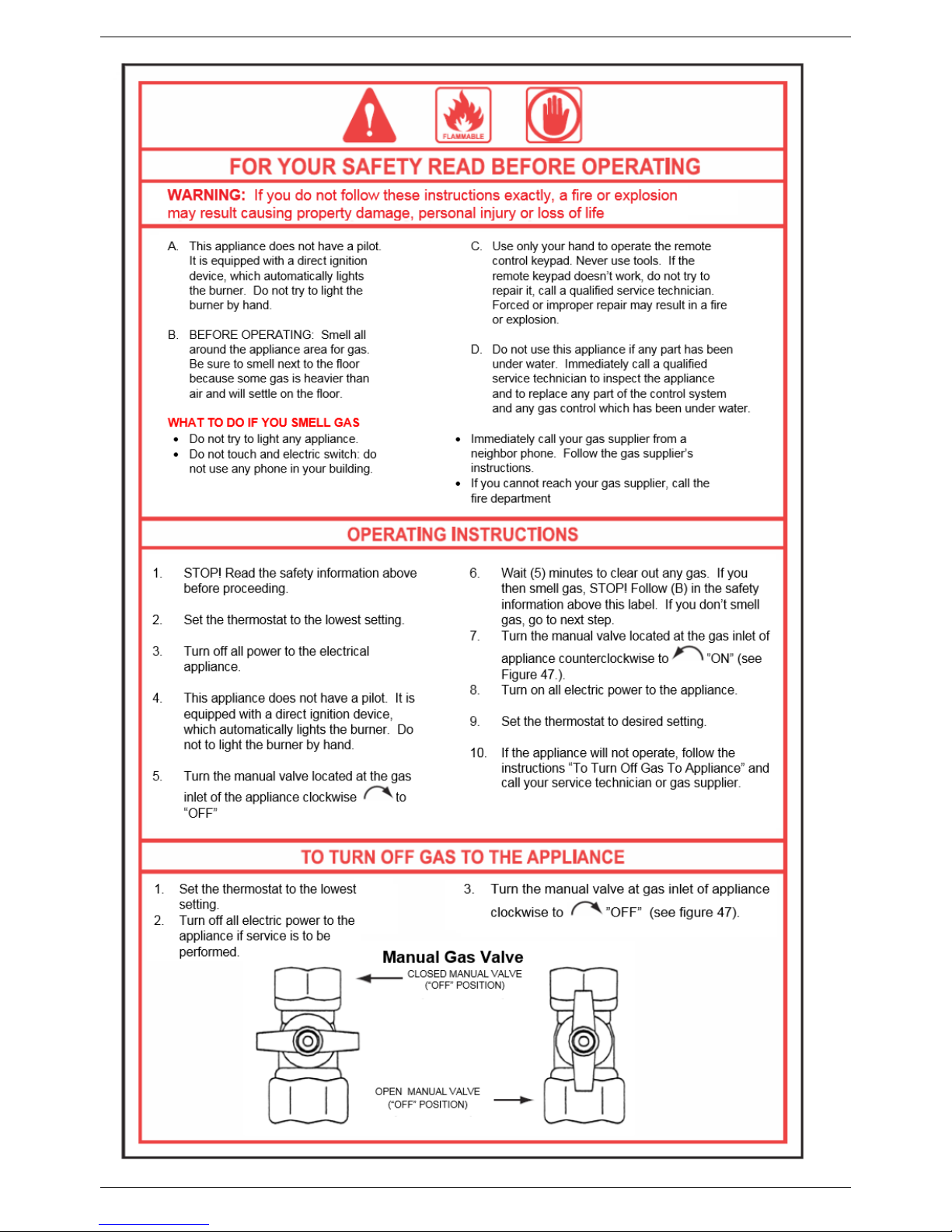
WARNING
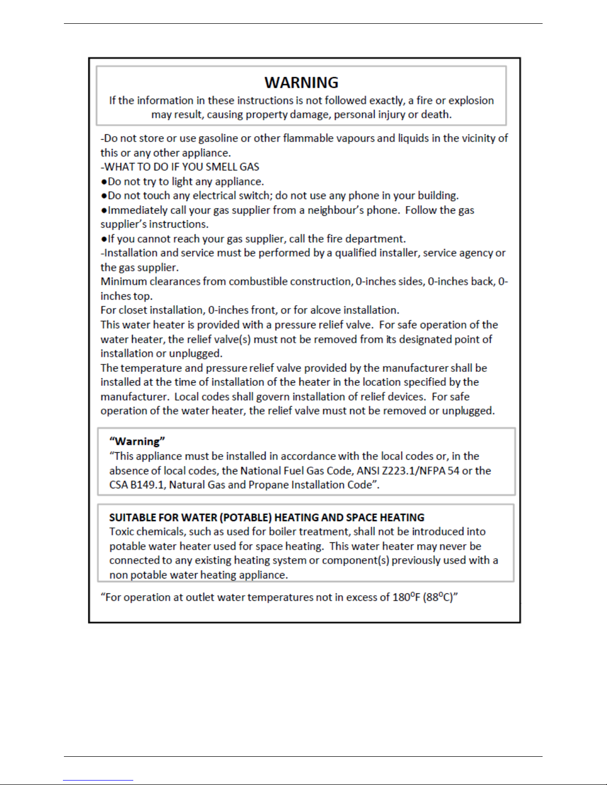
If the information in these instructions is not followed exactly, a fi re or explosion may result, causing p roperty damage, personal injury or death.
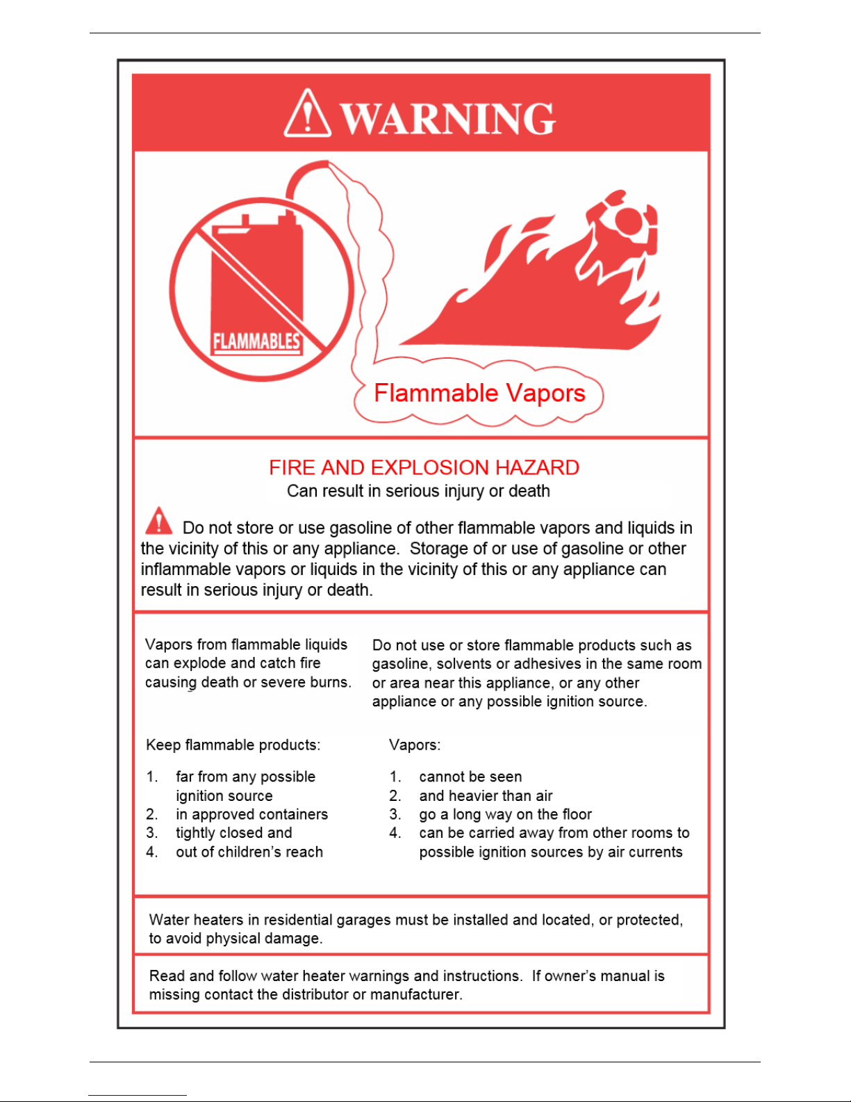
-Do not store or use gasoline or other flammable va pours and liq uids in the vicinity o f t his or any other applianc e.
-WHAT TO DO IF YOU SMELL GAS
●Do not try t o light any applia nce.
●Do not touch any elect rical switch; do not use any phone in your building.
●Immediately ca ll yo ur gas supplier from a neighbour ’s phone. Follow the gas supplie r ’s instruc tions.
●If you cannot reach your gas supplier, call the fire department.
-Installation and service must be performed by a qualified installer, service agency or the gas supplier.


CONTENTS
Pages
1. General information
1.1 General warnings 1
1.2 Product conformity 9
2. Technical characteristics
2.1 Technical data 10
2.2 Dimensions 11
2.3 Internal parts of the water heater 12
2.4 Water cir cuit 13
2.5 Circulation pump head/flow graph 14
2.6 Printed circuit board – Technical characterist ics 15
2.7 Control panel 15
3. Installation (authorized personnel)
3.1 Reference standard 16
3.2 Unpacking 17
3.3 Installation water heater 18
3.4 Fixing the water heater 19
3.5 Water connections 20
3.6 Domestic Hot Wat er Circuit/Hard W at er Warning/ Condensat e Dr ain 21
3.7 Schematic of Piping Installation 23
3.8 Gas connection 25
3.9 Electrical connections
26
3.10 Venting connections 29
4. Commissioning the appliance (authorized personnel)
4.1 General warnings 36
4.2 Filling the system 37
4.3 Flushing the system 38
4.4 Filling the condensate trap 38
4.5 Starting up the water heater 39
5. Regulating the appliance (authorized personnel)
5.1 Parameters table 40
5.2 Setting the parameters 41
5.3 Gas Data 48
5.4 Regulating the Gas Valve Offset 49

CONTENTS
Pages
6. Maintenance (authorized personnel)
6.1 General warnings 50
6.2 Maintenance 50
6.3 Water heat er inspection 50
6.4 Accessing the water heater 52
6.5 Flushing out the primary side 52
6.6 Draining the central heating and domestic hot water s ystem 53
6.7 Maintenance operations 54
6.8 Wiring diag r ams 60
6.9 D.H.W Sensor Connect ion 66
6.10 Troubleshooting 67
6.11 Diagnostics 68
6.12 Parts list 78
7. Warranty
7.1 Terms and Condition of Sale 79
7.2 Warranty Registrat ion For m 81
7.3 Warranty Parts Request Form 82
GENERAL INFORMATION
1
1. GENERAL INFORMATION
1.1 General warnings – Installation
Read all s afety warnings in the “Instruction Manual”. The additional safety issues outlined below must also be
followed completely when installing this FLOWMAX Combination Water heater.
Failure to remove or maintain the area free of combustible material, gasoline and other flammable liquids or
vapours can result in severe personal injury, death or substantial property damage.
All applicable local, state, national and provincial codes, ordinances, regulations and laws must be observed.
For installations in Massachusetts – code requires the units to be installed by a licensed plumbing or gas fitter.
The appliance cannot operate without the correct amount of air for combustion. Please make sure there is
sufficient inflow and outf low of air for ventilation; never obstruct the flow of ventilation air. Failure to provide the
proper amount of combustion air can result in a fire or explosion and cause death, serious bodily injury or
property damage.
If an external electrical source is utilized, the appliance, when installed, must be electrically grounded in
accordance with local codes or, in the absence of local codes, with the National Electrical Codes ANSI/NFPA 70
and or the CSA C22.1 Canadian Electrical Code.
Follow all local codes and/or the most recent edition of the National Fuel Gas Code (ANSI Z223.1/NFPA 54) in
the USA or the Natural Gas and Propane Installation Code in Canada (CAN/CSA B149.1).
This unit is designed for indoor installations. DO NOT operate this unit without the vent piping connected.
Exhaust gases must be completely expelled out of the building.
Do not use this appliance if any part has been underwater. Immediately call a qualified service technician to
inspect the appliance and replace any part of the control system and any gas control which has been
underwater.
Be sure not to reverse the water and gas connections as this may damage the gas valves.
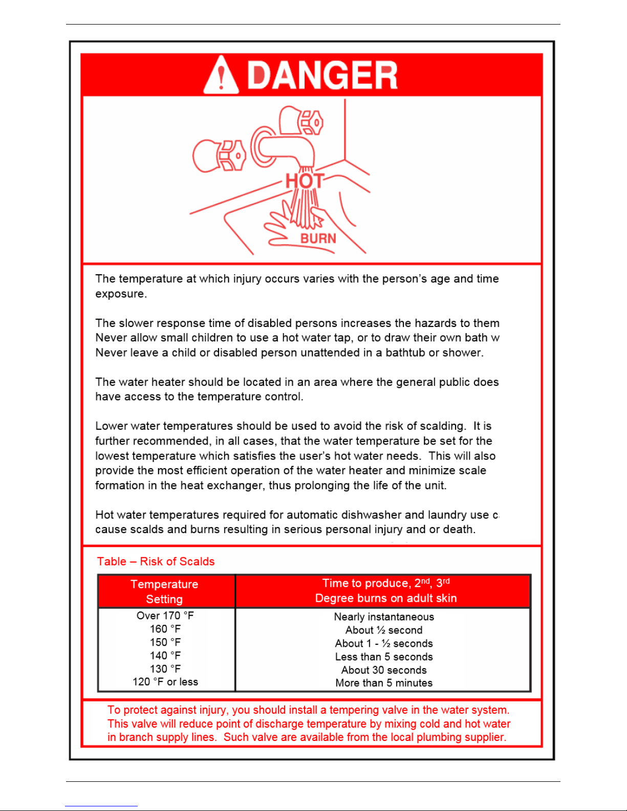
Water temperatures over 125⁰F can cause severe burns instantly or death from scalding. If the proposed water
heater outlet temperature is above 125⁰F, a thermostatically controlled mixing valve (or a temperature limiting
valve) for reducing point of use water temperature is recommended to reduce the risk of scald injury. Contact a
licensed plumber or the local plumbing authority for further information.
The appliance s hould be located in an area where leakage within the unit or at its connecti ons will not result in
damage to the area adjacent to the appliance or to lower floors of the structure. FLOWMAX will not be
responsible for any damage resulting from leaking if adequate drainage is not provided. W hen such locations
cannot be avoided, it is recommended that a suitable drain pan, adequately drained, be installed under the
appliance.
Do not use this combination water heater for any purpose other than water heating and space heating.
The fl ow of combustion air and ventilation to the water heater must not be obstructed. The water heater area
must be kept clear and free from combustible materials, gasoline and other flammable vapours and liquids.
If the water quality is known to be highly acidic and/or extremely hard, water treatments (ie water softeners and
filtration) are recommended to maintain full warranty. Consult the local water authority.
DO NOT over-tighten fittings, as pipe and/or fitting damage may occur causing leakage.
DO NOT install water heater where subject to vibrations.
For other than a direct vent appliance, the appliance must be loc ated as close as possible to a c himney or gas
vent.
Should overheating occur or the gas supply fails to shut off , turn the manual gas control valve to the appliance.
Contact a Service Technician immediately.
Clearance must be in accordance with the local installation codes and the requirements of the gas supplier.
GENERAL INFORMATION
2
Never operate the heater unless it is vented to the outdoors and has adequate air supply to avoid risks of
improper operation, fire, explosion or asphyxiation.
DO NOT ins tall this water heater directly on a carpeted floor. A f ire hazard may result. The water heater shall
be installed on a metal or wood panel extending beyond the full width and depth of the water heater by at least 3
inches (76.2mm) in any direction or, if the water heater is installed in an alcove or closet, the entire floor shall be
covered by the panel.
For safe operation, an ample supply of air must be provided for proper combustion and ventilation in accordance
with the National Fuel Gas Code ANSI Z223.1/NFPA 54 National Fuel Gas Code CSA/B149.1 Natural Gas and
Propane Installation Codes or applicable provisions of the local buil ding codes. An insuffic ient supply of air may
result in a yellow, luminous burner flame, carboning or sooting of the heat exchanger, or create a risk of
asphyxiation. Do not obstruct the flow of combustion and ventilation air.
This unit is not intended to operate at gas supply pressures other than those shown on the rating plate.
Exposure to higher gas supply pressure may cause damage to gas valves, which can result in fi re or explosion.
If over-pressure has occurred, such as through improper testing of gas lines or emergency malfunction of the
supply system, the gas valves must be checked for safe operation.
A thermostatic mixing valve must be added to this system to prevent scalding, if regulated by local codes and
authorities.
Check the Rating Plate
FLOW MAX units come from the factory configured for use with natural gas. Prior to installation, check the
rating plate of the water heater to ensure the unit matches gas type, gas pressure, water pressure and electrical
supply. If the unit does not match the requirements, do not install.
Be sure the gas type and electricity voltage match the rating plate.
There is a risk i n using fuel burning appliances in rooms or areas where gasoline, other flammable liquids or
engine-driven equipment or vehicles are stored, operate or are repaired. Flammable vapours are heavy and
travel along the floor and may be ignited by the igniter or main burner flames causing fire or explosion. Some
local codes permit operation of gas appliances if ins talled 18 inches or more above the floor. This may reduce
the risk if loc ation in such an area cannot be avoided. Flammable items, pressurized containers or any other
potential fire hazardous articles must never be placed on or adjacent to the water heater. Open containers of
flammable materials should not be stored or used in the same room with the water heater.
Do not install the FLOWMAX water heater in areas with excessive high humidity.
Do not install the unit in location where there is excessive humidity, such as a bathroom, damp crawl space and
other areas with high levels of humidity. This may cause the unit to malfunction.
To avoid possible electrical s hock, DO NOT touch the internal components of the water heater or the power
cord with wet hands.
DO NOT splash excessive water on the water heater when cleaning, as they are water resistant, not water
proof.
Professionally qualified personnel in accordance with current laws and standards and in line with the
manufacturer’s instructions must install the appliance.
The commissioning of the water heater and any subsequent works carried out on the appliance must be
effected by an appropriately qualified technician.
The appl iance must be used solely for the purpose f or which it has been designed and manufactured: central
heating and domestic hot water production. Any other use is deemed as improper and as such dangerous.
Under no circumstances will the manufacturer be held responsible for damage or injury to persons or animals
caused by errors in the installation and/or use of the appliance, or through non-compliance with current local
and national standards and/or the manufacturer’s instructions.
The install ation, operation and maintenance manual forms are an integral and essential part of the product and
must be kept with the appliance always.
The warnings contained i n this chapter have been written for the appliance user, the installer and the service
technician.

GENERAL INFORMATION
3
The “operating instructions” chapter of this manual must be read carefully as it provides information on the
operation and the operating limits of the appliance.
• After the removal of all the packaging, check that the appliance has not been damaged. In case of doubt, do not
attempt to use the product but refer to the supplier. Packing materials (cardboard box, wooden crate, nails, staples,
plastic bags, polystyrene, etc.) must not be left within reach of children in that these items represent a potential
hazard and must be disposed of in a responsible manner.
• Before carrying out any cleaning or maintenance operations, disconnect the appliance from the mains electricity
supply by switching off at the main switch and/or any other isolating device.
• In the case of a fault and/or malfunction in the appliance, shut down the s ystem. Do not interfere with or attempt any
repairs. Call for professionally qualified technical assistance only.
• Any warranty repairs to the appliance must be carried out exclusively by the manufacturer’s authorized service
dealers using original spare parts. Non-compliance with the above requirements may compromise the safety of the
appliance and invalidate the warranty. In order to guarantee the efficiency of the appliance and its c orrect operation, it
must be serviced regularly by professionally qualified personnel in line with the manufacturer’s instructions .
• Only original accessories or optional extras (including electrical parts) must be used with the applianc e.
• Should there be a smell of gas present in the room where the appliance is i nstalled, DO NOT attempt to activate any
electric switches, telephones or any other equipment that may cause sparks. Open doors and windows immediately to
create a current of air and ventilate the room. Shut-off the main gas supply valve (at the meter), or on the cylinder in
the case of bottled gas, and call an authorized service centre.
• Do not attempt to interfere with the appliance in any way.
• As dictated by current legislation, this appliance must be installed exclusively by qualified personnel. Before
starting the water heater for the first time, make sure that it is connected to a water supply and central heating system
compatible with its performance characteristics.
• Prior to start-up, the central heating pipes should be flushed to remove any residues that could compromise the
operation of the appliance.
• The domestic power supply must be checked by a qualified electrician to ensure that it can support the maximum
power absorption of the appliance, as indicated on the appliance rating plate (positioned on the casi ng). In particular,
make sure that the cable ratings are adequate for the power absorbed.
• Do not use adapters; multiple sockets or extension leads to connect the appliance to the power supply.
• The appliance must be connected to the mains power supply through an appropriate electrical isol ator in accordance
with the current wiring regulations.
• If the cable is damaged in any way, switch off the appliance and have the cable replaced by a suitably qualified
technician.
• When the appliance is no longer required for use, switch off the main power supply, to switch all electrical
components off (circulating pump, burner, etc).
GENERAL INFORMATION
4
Important: Carbon Monoxide Detectors
Many jurisdictions require the installation of carbon monoxide detectors in building where a side wall vented fuel burning
appliance is installed. Installers must abide by local code requirements regarding the installation of CO detectors. The
use of a certified carbon monoxide detector is recommended but not required by FLOWMAX.
“In the State of Massachusetts only”
(a)For all horizontally vented gas fuelled equipment installed in every dwelling, building or structure used in whole or in
part for residential purposes, including those owned and operated by the Commonwealth and where the side wall
exhaust vent termination is less than seven (7) feet above finished grade in the area of the venting, including but not
limited to decks and porches, the following requirements shall be satisfied:
1. INSTALLATION OF CARBON MONOXIDE DETECTORS. At the time of installation of the si de wall
horizontal vented gas fuelled equipment, the installing plumber or gas fitter shall observe that a hard wired
carbon monoxide detector with an alarm and battery back-up is installed on the floor level where the gas
equipment is to be installed and on each additional level of the dwelling, building or structure served by the
equipment. It shall be the responsibility of the property owner to secure the services of qualified licensed
professionals for the installation of hard wired carbon monoxide detectors.
a. In the event that the side wall horizontally vented gas fuelled equipment is installed in a crawl space
or an attic, the hard wired carbon monoxide detector with alarm and battery back-up may be
installed on the next adjacent floor level.
b. In the event that the requirements of this subdivision cannot be met at the time of completion of
installation, the owner shall have a period of 30 days to comply with the above requirements;
provided, however, that during said 30 day period a battery operated carbon monoxide detector with
alarm shall be installed.
2. APPROVED CARBON MONOXIDE DETECTORS. Each carbon monoxide detector as required in
accordance with the above provisions shall comply with NFPA 720 and be ANSI/UL 2034 listed and IAS
certified.
3. SIGNAGE. A metal or plastic identification plate shall be permanently mounted to the exterior of the building
at a minimum height of eight (8) feet above grade directly in line with the exhaust vent terminal for the
horizontally vented gas fuelled heating appliance or equipment. The sign shall read, in print size no less than
one-half (1/2) inch in size, “GAS VENT DIRECTLY BELOW. KEEP CLEAR OF ALL OBSTRUCTIONS”.
4. INSPECTION. The state or local gas inspector of the side wall horizontally vented gas fuelled equipment
shall not approve the installation unless, upon inspection, the inspector observes carbon monoxide detectors
and signage installed in accordance with the provisions of 248 CMR 5.08(2)(a) 1 through 4.
GENERAL INFORMATION
5
GENERAL INFORMATION
6
GENERAL INFORMATION
7
GENERAL INFORMATION
8

GENERAL INFORMATION
9
1.2 Product conformity
All FLOWMAX water heaters are ETL certified and possess technical and functional characteristics that comply with
the following standards:
Gas fired water heaters also comply with the following directives:
American National Standard/CSA Standard for Gas Water Heaters Volume III, Storage W ater Heaters with input
Ratings above 75,000 Btu per Hour, Circulating and Instantaneous. Conform s to ANSI STD Z21.10.3, certified to
CSA STD 4.3.
The materials used suc h as copper, brass, stainless steel, etc. form a compact, homogeneous, highly functional
unit that is easy to install and simple to operate. In its simplic ity, the wall-mounted appliance is equipped with all the
appropriate accessories required to m ake it a fully independent water heater capable of satisfying domestic hot
water production and central heating needs. All water heaters are fully inspected and are accompanied by a quality
certificate, signed by the inspec tor, and a guarantee c ertific ate. T his m anual m us t be k ept in a safe plac e and must
accompany the water heater at all times.
FLOWMAX will not be held responsible for any misinterpretation of this manual resulting from the
inaccurate translation of same.
FLOWMAX will not be held responsible for the consequences in the case of non-observance of the
instructions contained in thi s manual or in the case where actions not specifically described herein are
undertaken.
TECHNICAL CHARACTERISTCS
10
2. TECHNICAL CHARACTERISTICS
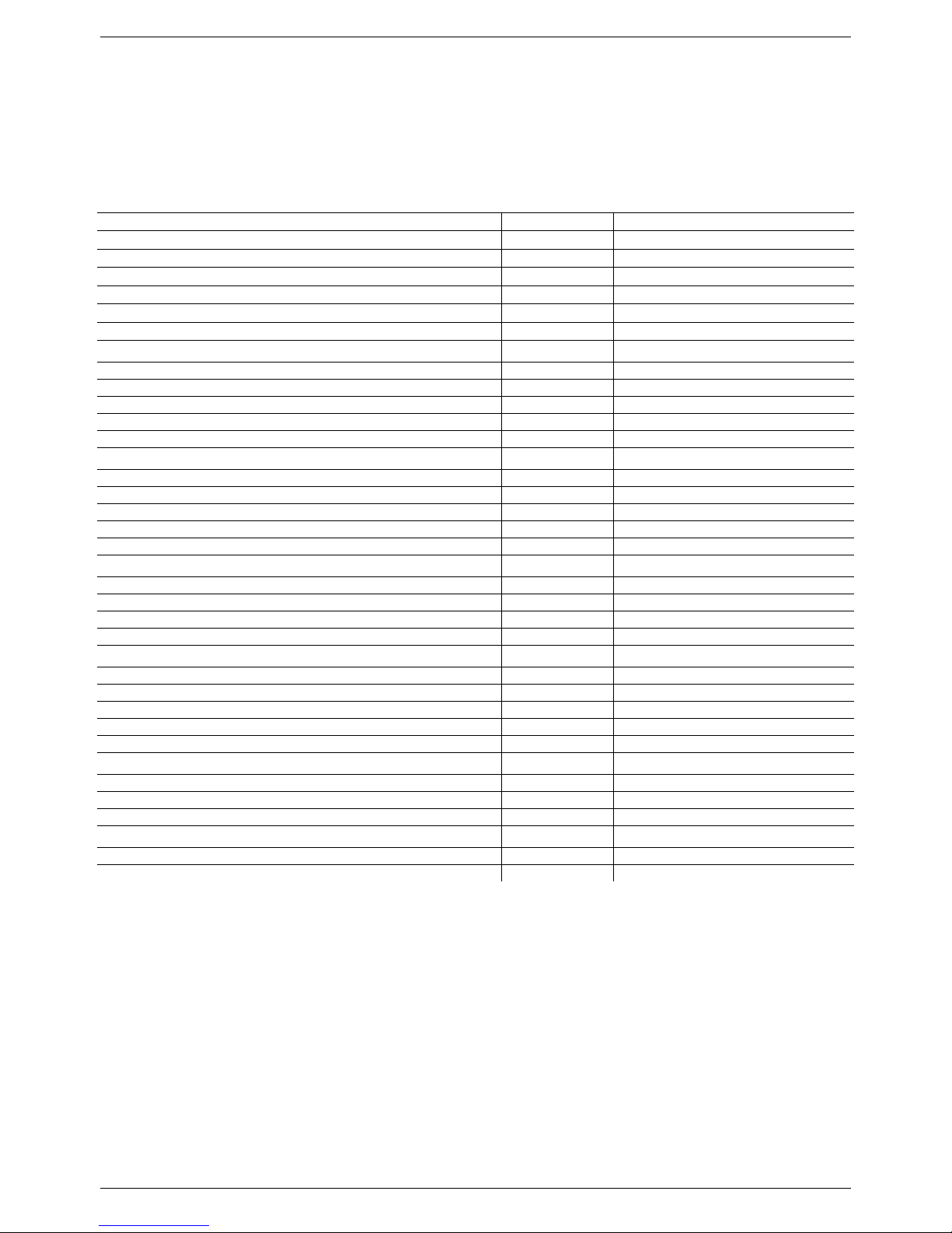
2.1 Technical data
Model FLOWMAX 170
Heat Input max
kW - BTU/hr
51 - 174019
Heat Input min
kW - BTU/hr
12 – 40946
Heat Output max - 122/86°F
kW - BTU/hr
54.5 – 185859
Heat Output max - 167/140°F
kW - BTU/hr
49.9 – 170198
Heat Output min - 167/140°F
kW - BTU/hr
11.65 - 39758
Efficiency 100% (full load 167/140°F)
%
97.8
Central Heating circuit
Central Heating water temperature setting (min-max)
°C – °F
30-75 / 25-40 – 86-167 / 77-104
Max. heating working temperature
°C – °F
75/167
Expansion vessel capacity
gal
1.58
Max. working pressure (heating)
bar - psi
2.1 - 30
Min. working pressure (heating)
bar - psi
0.3 - 4.29
Domestic Hot Water circuit
D.H.W. temperature setting (min-max)
°C – °F
35-60 – 95-140
Max. Hot water working pressure
bar - psi
6 - 86
Min. Hot water working pressure
bar - psi
0.5 - 7.16
D.H.W. flow rate at ∆T 45°F (25°C)
l/min - gal/min
30 - 7.93
D.H.W. flow rate at ∆T 72°F (40°C)
l/min - gal/min
18.8 – 4.95
Dimensions (Water heater casing size)
Width
in
19.3
Height
in
27.6
Depth
in
18.5
Weight (net)
lb
120
Hydraulic connections
Central Heating Flow connection
NPT
3/4"
Central heating Return connection
NPT
3/4"
Cold water mains connection
NPT
1/2"
D. Hot water connection
NPT
3/4"
Gas connection
NPT
3/4"
Gas Supply
Natural gas G 20
Inlet pressure
mbar - psi
20 - 0.29
Gas consumption
m3/h - ft3/h
5.40 – 190.7
Electrical specifications
Power supply
V/Hz
120/60
Electrical power consumption
W
225
TECHNICAL CHARACTERISTCS
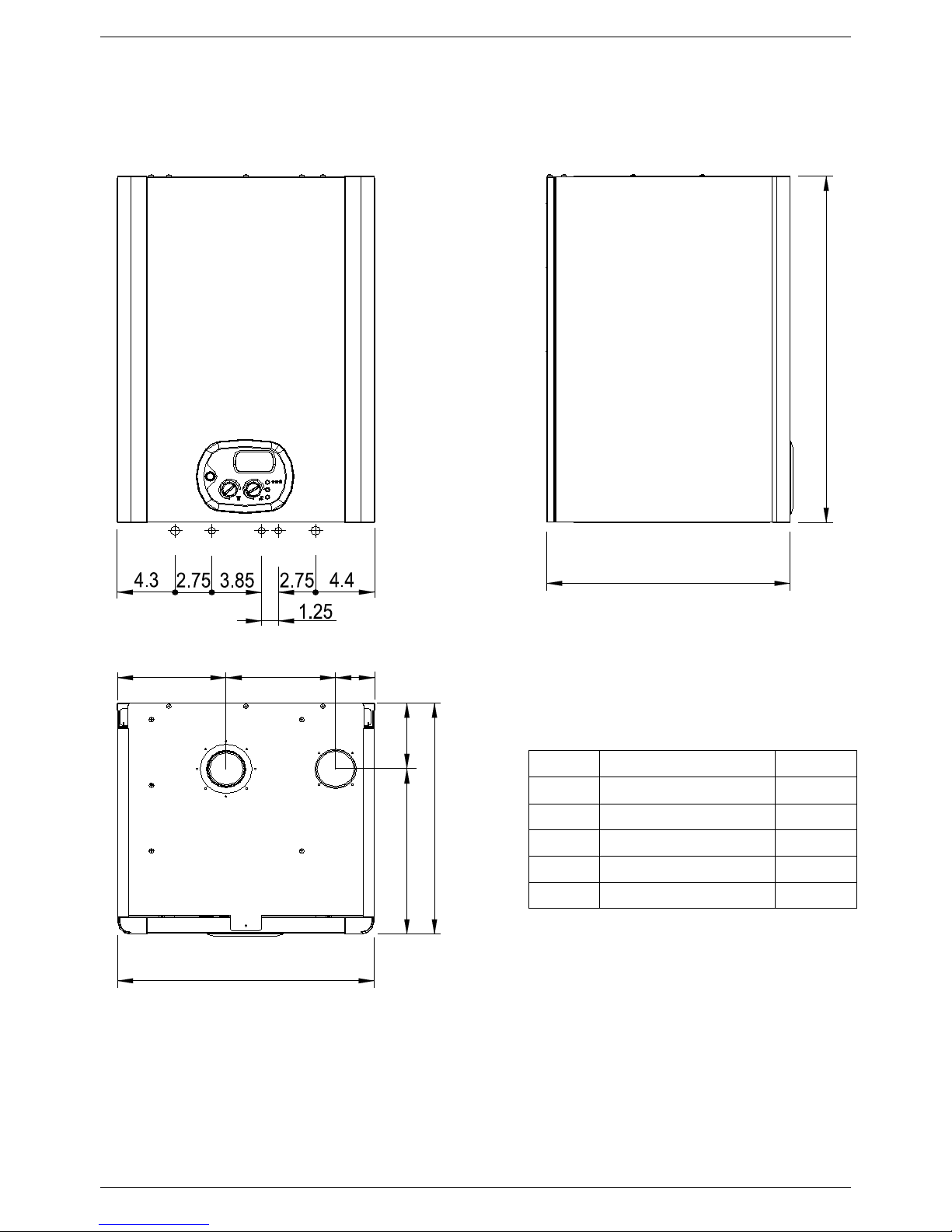
11
18.5
18.5
5.313.2
19.3
27.6
8.3
8.3
2.7
HWO G
CWI
HI
HO
2.2 Dimensions
LEGEND
HI
HEATING INTAKE
Ø 3/4"
HO
HEATING OUTLET
Ø 3/4"
G
GAS
Ø 3/4"
CWI
COLD WATER INLET
Ø 1/2"
HWO
HOT WATER OUTLET
Ø 3/4"
SC
CONDENSATE DRAIN
Ø 0.98 in
TECHNICAL CHARACTERISTCS
12
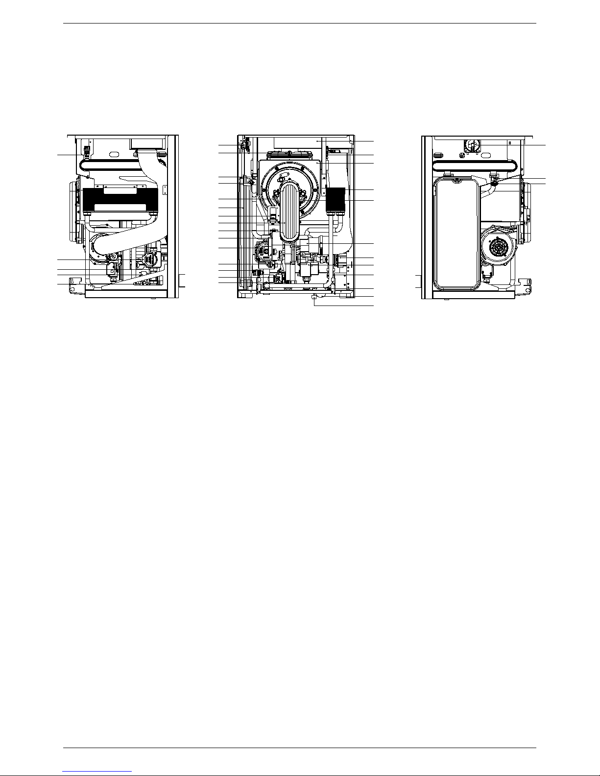
2.3 Internal parts of the wat er heater
LEGEND
1. AIR PRESSURE SWITCH
2. SAFETY THERMOFUSE
3. HEATING SENSOR
4. HEATING SAFETY THERMOSTAT
5. IONIZATION ELECTRODE
6. EXPANSION TANK
7. IGNITION TRANSFORMER
8. FLOWMAX BURNE R UNIT (GAS MANIFOLD + BURNER)
9. AUTOMATIC AIR VENT VALVE
10. FAN
11. PUMP
12. CONDENSATE TRAP
13. AIR VENT VALVE 1/4
14. SAFETY VALVE 3/4
15. D.H.W. SENSOR
16. EXHAUST HOOD
17. PRIMARY CONDENSING HEAT EXCHANGER
18. D.H.W. EXCHANGER
19. IGNITION ELECTRODE
20. VENTURI
21. DIVERTER ACTUATOR VALVE
22. ELECTRONIC GAS VALVE
23. WATER PRESSURE SWITCH
24. NO-RETURN VALVE
25. WATER PRESSURE GAUGE
26. FILLING TAP
27. ELECTRONIC FLOWSWITCH
1
2
4
5
6
7
8
9
10
11
13
14
15
16
3
12
1
3
4
13
13
17
18
19
20
21
22
23
24
25
26
21
27
23
24
TECHNICAL CHARACTERISTCS
13
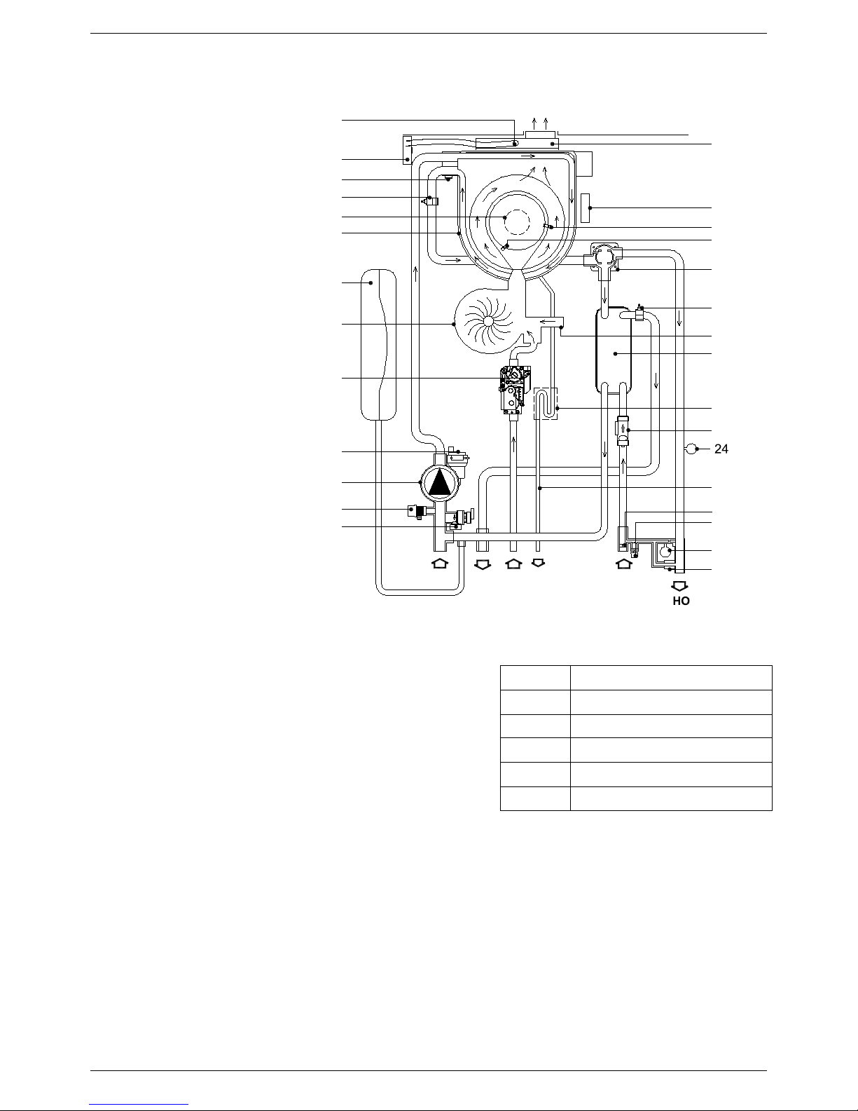
2.4 Water circuit
LEGEND
1. SAFETY THERMOFUSE
2. AIR PRESSURE
SWITCH
3. HEATING SAFETY THERMOSTAT
4. HEATING SENSOR
5. FLOWMAX BURNE R UNIT (GAS MANIFOLD+BURNER)
6. P RIMARY CONDENSING HEAT EXCHANGER
7. EXPANSION VESSEL
8. FAN
9. ELECTRONIC GAS VALVE
10. AUTOMATIC AIR VENT VALVE
11. PUMP
12. AIR VENT VALVE 1/4
13. PRESSURE RELIEF VALVE
14. EXHAUST HOOD
15. IGNITION TRANSFORMER
16. IGNITION ELECTRODE
17. IONIZATION ELECTRODE
18. DIVERTER ACTUATOR VALVE
19. D.H.W. SENSOR
20. VENTURI
21. D.H.W. EXCHANGER
22. CONDENSATE TRAP
23. ELECTRONIC FLOWSWITCH
24. WATER PRESSURE SWITCH
25. CONDENSATE DRAIN PIPE
26. FLOW LIMITER
27. FILLING TAP
28. WATER PRESSURE GAUGE
29. NO-RETURN VALVE
LEGEND
HI
HEATING INTAKE
HO
HEATING OUTLET
G
GAS
CWI
COLD WATER INLET
HWO
HOT WATER OUTLET
SC
CONDENSATE DRAIN
3
6
4
11
10
9
8
14
5
1
G CWIHWO
SC
12
15
16
17
18
19
20
21
22
23
25
7
2
13
26
27
28
29
HI
TECHNICAL CHARACTERISTCS
14
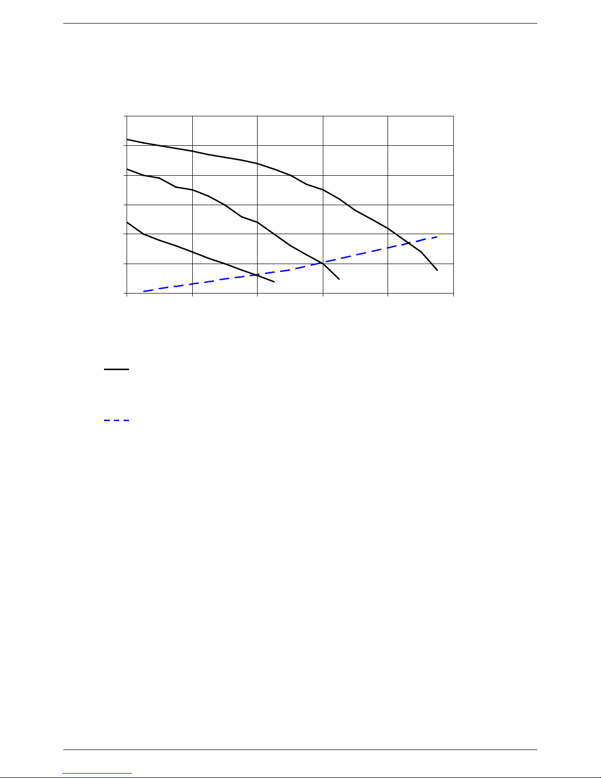
2.5 Circulati on pum p he a d/flow gr a ph
Pump head
I, II, III Pump speed
Water heater
losses
I
II
III
0
5
10
15
20
25
30
0 2 4 6 8 10
Water flow (US gpm)
Head (ft)
TECHNICAL CHARACTERISTCS
15
2.6 DIGITECH® printed circ uit board – SM 20021
Technical characteristics
Adjustments possible by service personnel only
• Standard (86-167°F) / reduced (77-104°F) central heating temperature
• Water hammer prevention function
• Central Heating timer - (adjustable from 0 to 7,5 minutes)
• Central Heating pump overrun timer
• Domestic Hot Water pump overrun timer
• Minimum Gas pressure setting
• Maximum Heating Load
• D.H.W. temperature setting 95-160°F
User settings
• On/Off
• Heating Temperature setting (86-167°F) – (77-104°F)
• D.H.W. temperature setting (95-140°F) – (95-160°F)
• Summer only mode / Winter only mode / Summer + Winter mode selection
Operation/Functions display
• Lock-Out
• Water deficiency indicator
• Temperature display
When the water heater is switched off at the switch on the control panel, the word OFF appears on the
display. The D.H.W and central heating frost protec tion system, nevertheless, remain enabled. If the
water heater was previously on, it is switched off and the post-ventilation, pump overrun , circulation
pump and three-way valve inactivity protection functions are enabled.
The remote control, where fi tted, remains active and illuminated.
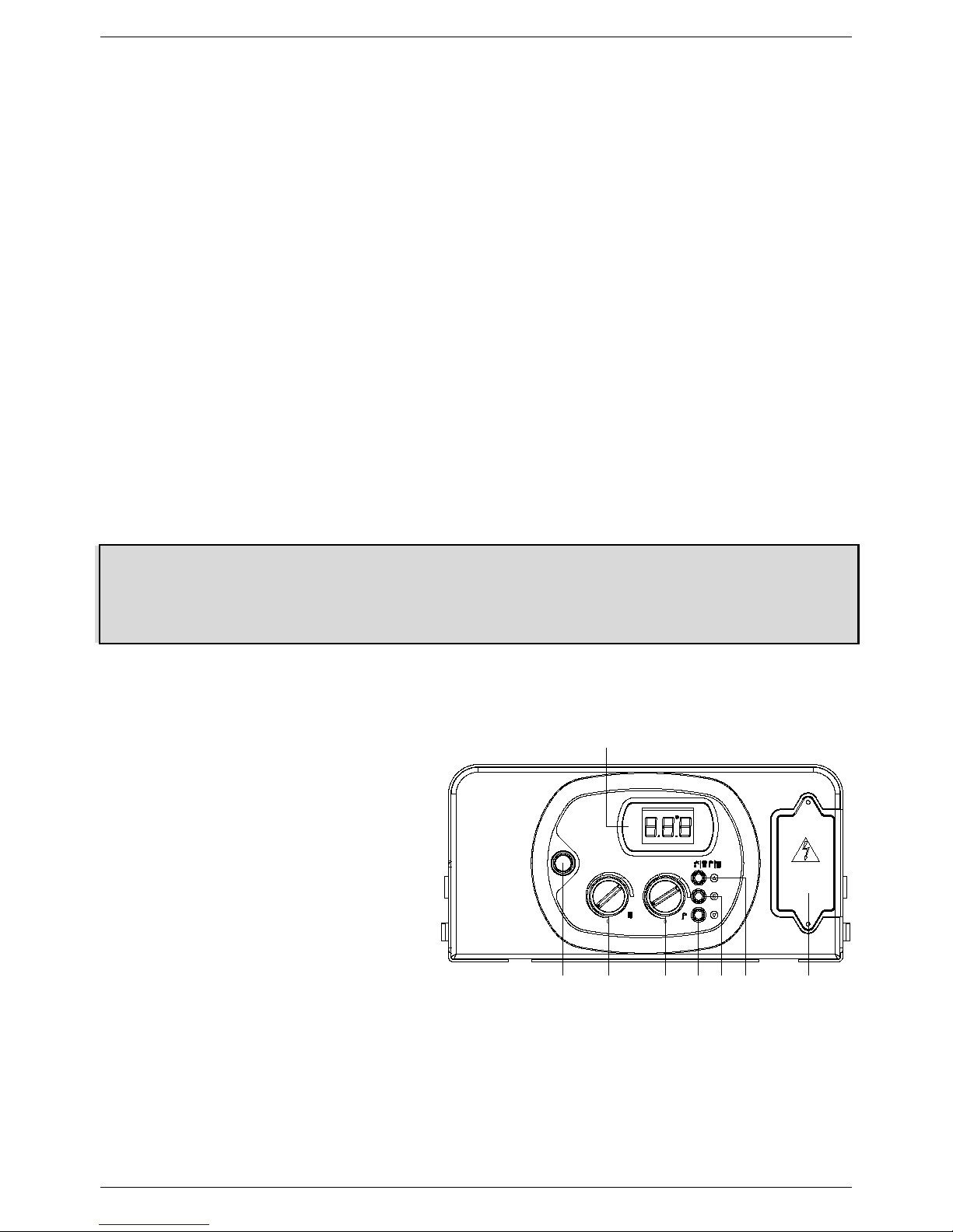
2.7 Control panel
LEGEND
1. ON/OFF SWITCH
2. HEATING TEMPERATURE CONTROL KNOB
3. D.H.W TEMPERATURE CONTROL KNOB.
4. D.H.W TEMPERATURE BUTTON. KEEP
PRESSED FOR 5 SECONDS TO DISPLAY
OUTSIDE TEMPERATURE (ONLY WITH
OPTIONAL OUTDOOR SENSOR)
5. SERVICE BUTTON.
6. SUMMER, WINTER OR SUMMER/WINTER
MODE SELECTION BUTTON.
7. TERMINAL BOARD FOR EXTERNAL WIRING.
8. TEMPERATURE, ERROR CODE AND
OPERATING STATUS DISPLAY
6 7543
21
8
120V 60Hz

INSTALLATION INSTRUCTIONS
16
3. INSTALLATION (authorized personnel)
3.1 Reference standard
Install in accordance with CEC and NEC. All wiring shall conform to CEC , NEC and local building and electrical
codes.
This appliance meets the requirements of:
American National Standard/CSA Standard for Gas Water Heaters Volume III, Storage W ater Heaters with input
Ratings above 75,000 Btu per Hour, Circulating and Instantaneous. Conform s to ANSI STD Z21.10.3, certif ied to
CSA STD 4.3.
Failure to install a gas appliance correctly and in accordance with the above norms could lead to prosecution. It is in
the interest of the installer and safety that the law is complied with.
The manufacturer’s instructions form an integral part of the installation and should be left with the appliance but do
not over ride in anyway statutory obligations.
Installation requirements
Please refer to local and national standards in force with the Country of destination of the product.
INSTALLATION INSTRUCTIONS
17
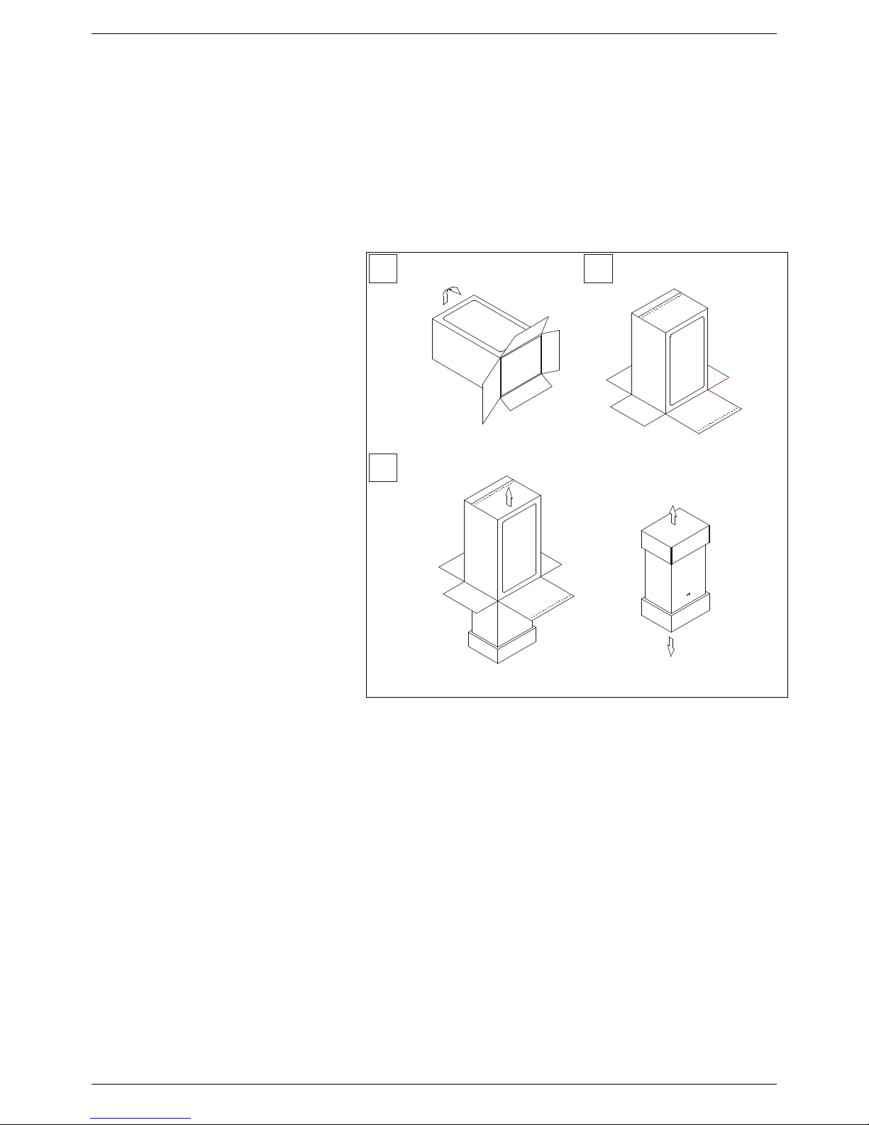
3.2 Unpacking
■ The materials (cardboard) used for packing the appliance are fully recyclable.
■ It is recommended that the packing material is only removed prior to installing the water heater. The
manufacturer will not be held responsible for damage caused by incorrect storage of the product.
■ Packing materials (plastic bags, polystyrene, nails, etc.) must not be left within reach of children, in that
these items represent a potential hazard.
A. Place the packed appliance on the f loor
(see fig. 1) m aking sure that the "up” arrow
is facing down. Remove the staples and
open out the four flaps of the box.
B. Rotate the water heater 90° while
manually supporting it from underneath
C. Lif t the box and remove the protections.
Lift the water heater by grasping the rear
part and proceed with the installation.
STORAGE & HANDLING
Please note that prior to installation the
Radiant water heaters should be stored in
the horizontal position with no more than
three water heaters to a stack;
Ensure that the water heaters are stored in
dry conditions and be aware that the carton
is a tow-man lift;
B
C
A
Fig. 1
INSTALLATION INSTRUCTIONS
18
3.3 Installing the water heater
The appliance must be installed
exclusively on a vertical solid wall capable
of supporting its weight. The
water heater should be fitted within the
building unless otherwise protected by a
suitable enclosure i.e. garage or
outhouse. (The water heater may be fitted
inside a cupboard)
■ If the water heater is sited in an
unheated enclosure then it is
recommended to leave the ON/OFF
switch always in ON position to give
frost protection.
In order to allow access to the interior of
the water heater for maintenance
purposes, it is important that the
minimum
distances
indicated in figure 2 are
respected
. To make the installation
easier, the water heater is s upplied with a
template to enable the pipe connections
to be positioned prior to fixing the
appliance to the wall.
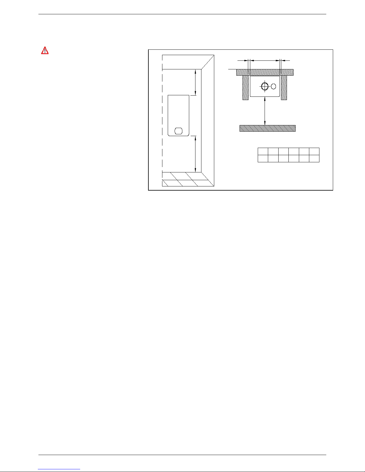
To install the water heater, proceed as follows (see fig. 2):
a. Use a s pirit level (of not less than 25 m m long) to m ark a horizontal line on the wall where the water heater is to
be fitted.
b. Position the top of the tem plate along the line drawn with the level, respecting the distances indicated. Then
mark the centr es of the positions of the two wall-plugs or anchor s. Finally, mark the positions of the water and
gas pipes.
c. Rem ove the template and install the supplied bracket sec urely to the wall. Once the water heater is securely
installed, connect the domestic hot and cold water pipes, the gas supply pipe and the central heating pipes
using the fittings supplied with the water heater.
d. Clearance to Combustibles-
Front –0 inches
Sides – 0 inches
Rear – 0 inches
Top – 0 inches from jacket cover
MINIMUM DISTANCE [INCHES]
H
A
X
L
Y
X Y L H
24200
FLOWMAX-170
B
A B
12 12
0
Model
Fig. 2
INSTALLATION INSTRUCTIONS
19
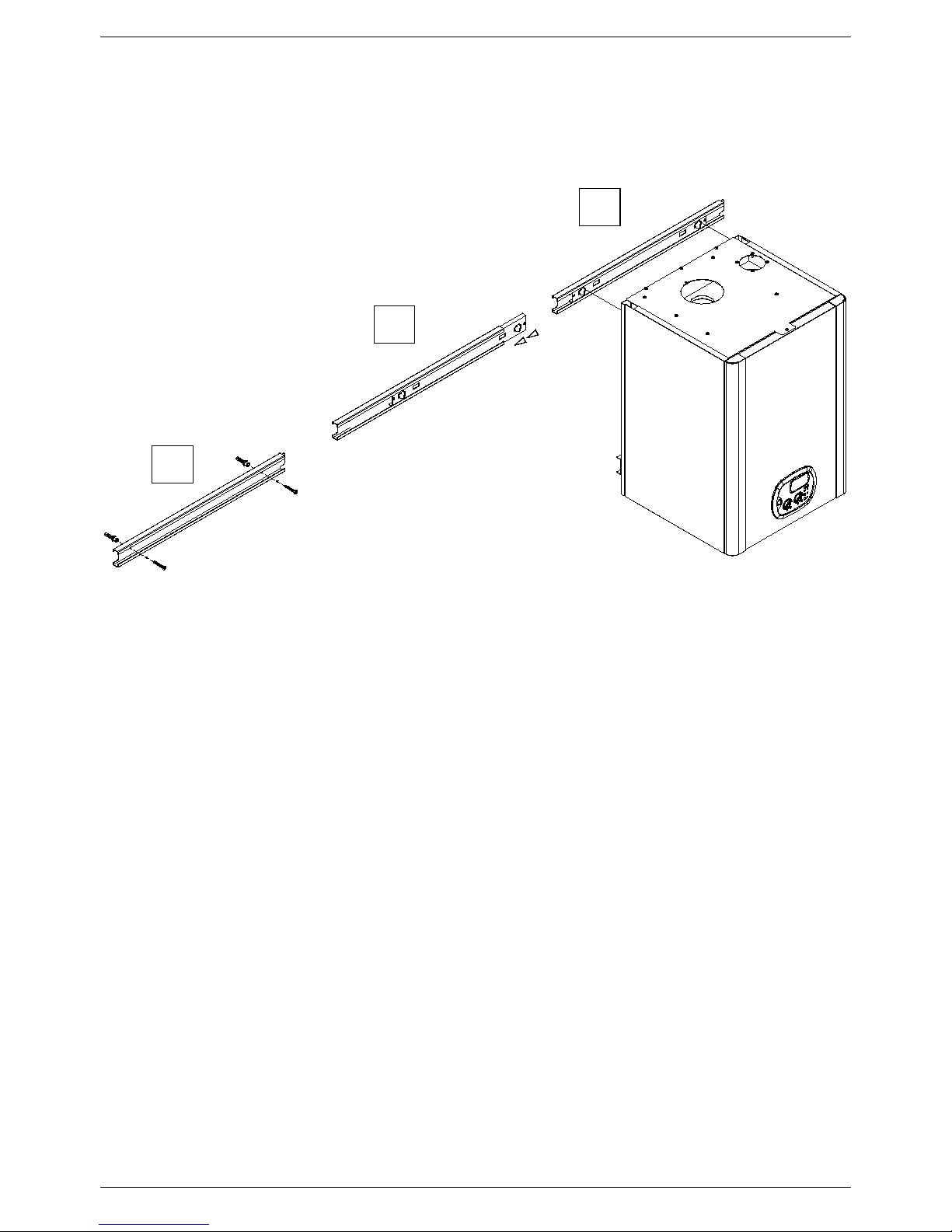
3.4 Fixing the water heater to wall
1
2
3
Instructions as follows:
1) Fix the external part of mounting bracket to wall using proper screw anchors.
2) Insert the inner guide of mounting bracket
3) Hang the water heater onto the opposite hooks.
INSTALLATION INSTRUCTIONS
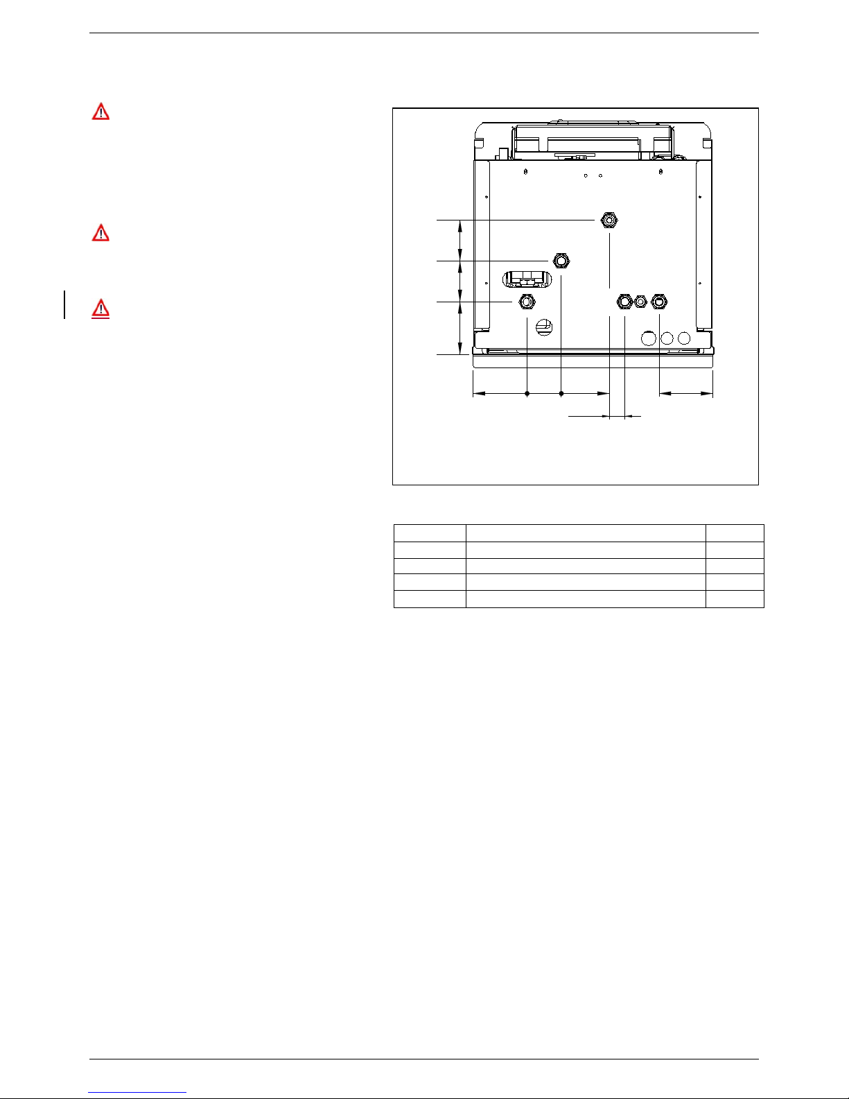
20
G
CWI
4.3 2.75 3.85
4.4
1.25
4.3 3.25 3.25
HWO
HI
HO
3.5 Water connecti ons
In order to safeguard the heat exchanger
and circulation pum p, especially in case
of water heater replacement, it is
recommended that the system is hotflushed to remove any impurities
(especially oil and grease) from the pipes
and radiators.
Make sure that the domestic water and
central heating pipes are not used to
ground the electrical system. The pipes
are totally unsuitab le for this purpose.
Isolation Valves must be installed on the
heating and D.H.W circuits. This will
facilitate all maintenance and service
operations where the water heater needs
to be drained.
■ To prevent vibration and noise coming from
the system, do not use pipes of reduced
diameter, short radius elbows or severe
reductions in the cross sec tions of the water
passages.
In order to guarantee the reliability of the
water heater and prevent permanent damage
in areas with high water inlet pressure too, a
36.3 psi (2.5 bar) pressure reducing valve
should be fitted.
■ The water flowing out of the pressure/relief
valve during its operation may be extremely
hot. Before operating relief valve, make sure
drain line is installed to direct discharge to a
safe location such as an open drain. Avoid
scalding and/or water damage.
A pressure relief valve is installed in this dual purpose water heater that is rated in accordance with and com plying
with either The Standard for relief Valves and Automatic Shutoff Devices for Hot Water Supply Systems, ANSI
Z21.22 CSA 4.4 Code.
The relief valve must be installed such that the dis charge will be conducted to a suitable place for disposal when
relief occurs and that no reducing coupling or other restriction be installed in the dischar ge line. The discharge line
must be installed to allow complete drainage of both the valve and the line. If this unit is inst alled with a separate
storage vessel, the separate vessel must have its own temperature and pressure r elief valve. No valve is to be
placed between the relief valve and the tank. This valve must also com ply with The Standard for Relief Valves and
Automatic Shutoff Devices for Hot W ater Supply Sys tems. ANSI Z21.22 or CSA 4.4. If a relief valve discharges
periodically, this may be due to the thermal expansion in a closed water system.
Contact the water supplier or local plumbing inspector on how to correct this situation. Do not unplug relief valve.
LEGEND
HI
HEATING INTAKE
Ø 3/4
HO
HEATING OUTLET
Ø 3/4
G
GAS
Ø 3/4
CWI
COLD WATER INLET
Ø 1/2
HWO
HOT WATER OUTLET
Ø 3/4
Fig. 1

INSTALLATION INSTRUCTIONS
21
3.6 Domestic hot water circuit/ Condensate Drain
Warning/ Hard Water
If this water heater is installed in an application where the supply water is hard, it must be treated with either
a water softener and filtration, which removes the hardness, or by using sequestering agents that reduce
the amount of scale deposits.
Damage to the water heater as a result of water in excess of 14.5 gpg (250mg/L) of hardness is not
covered by FLOWMAX Limited warranty. If there a problem with the water quality, contact your local water
conditioning company for equipment to condition the water supply to this appliance
The cold water supply pressure at the inlet to the water heater must be between 7.25 psi (0.5 bar) and 87 psi
(6 bar).
In areas with higher water inlet pressure a pressure reducing valve must be fitted before the water heater.
The frequency of the heat exchanger coil cleaning depends on the har dness of the mains water supply and the
presence of residual solids or impurities, which are often present in the case of a new installation. If the
characteristics of the mains water supply are such that require it to be treated, then the appropriate treatment
devices must be installed, while in the case of residues, an in-line filter should be sufficient.
Central heating circuit
In order t o prevent scaling or deposits in the primar y heat exchanger, the mains supply water to the heating circuit
must be treated according to the requirements of local standards.
This treatment is indispensable in the c ase where the circuit is frequently topped-up or when the system is often
either partially or fully drained.
Condensate Drain
■ FLOWMAX water heater is a high efficient gas appliance that creates condensation when it operates. A
condensate trap and flexible drain pipe comes factory installed inside each water tank.
The condensate trap must be primed before operation to prevent exhaust gases from entering the building.
■ Follow your local code with regards to the disposal of condensation
■ Here are several options for disposal of condensate
o From combination water heater direct to drain
o From combination water heater to neutralizer to drain
o From combination water heater to laundry tub (bottom of water heater must be above the height of
the laundry tub; must have a negative slope to properly drain)
o From combination water heater to condensate pump to laundry tub (for long distances between
water heater and laundry tub or when bottom of the water heater is installed below height of the
laundry tub)
■ Failure to install the condensate discharge properly will affect the reliability of the water heater.
For all units installed with vertical exhaust, must have an additional approved condensate drain. Fittings
must be ULC S636 approved.
Failure to properly connect the condensate line will cause combustion gases to enter the room, possibly
causing serious injury to occupants or death.
Note: Check with your municipality, local codes, or local gas company to determine if disposal of
combustion condensate is permitted. In the State of Massachusetts the condensate must be
neutralized prior to entering a drain
■ Use only PVC, Vinyl or CPVC pipe for the condensate drain line, metal pipe work is not suitable for
condensate discharge system.
■ The condensate drain line should be a minimum of 1/2” diameter that connects to the 7/8” supplied hose
and must be supported to prevent sagging. Manufacturer will supply a ¾” to ½” reducer for connection.
■ Keep the length of the condensate drain as short as possible. Long runs or applications where the nearest
drain is above the water heater will require the use of a condensate pump. Size the pump to allow for a
maximum condensate discharge of 2 gpm from the water heater. The end drain pipe must not be
submerged in water or blocked in any way.

INSTALLATION INSTRUCTIONS
22
■ The condensate pump must be installed with an overflow safety switch that detects downstream clogs and
shuts off the water heater before flooding occurs. See condensate pump manufacture for installation
instructions.
■ Be sure to check that condensate is freely flowing from the drain piping after the system has been installed.
Condensate will begin flowing out of the water heater within 15 minutes after operation has started.
■ Do not run condensate line outside and take measures to prevent the condensate drain lines from freezing
(insulation, heat tape, electric heaters, etc.)
■ Be sure to clean the condensate trap at least once per year to prevent any problems, and after cleaning be
sure to check for any leaks of condensed water or flue gas.
Space Heating
This water heater is suitable for water (potable) heating and space heating.
Piping and components connected to the water heater f or t he spac e heating application s hall be suitable for
use with potable water.
Toxic chem icals, such as used for water heater treatm ent, shall not be introduced into the potable water
used for space heating.
A water heater which will be us ed to supply potable water shall not be connected to any heating system of
component(s) previously used with nonpotable water heating appliance.
W hen the system requires water for the space heating at temperat ures higher than r equired for other uses ,
a means suc h as a mixing valve shall be installed to temper the water for those uses in order to reduce
scald hazard potential.
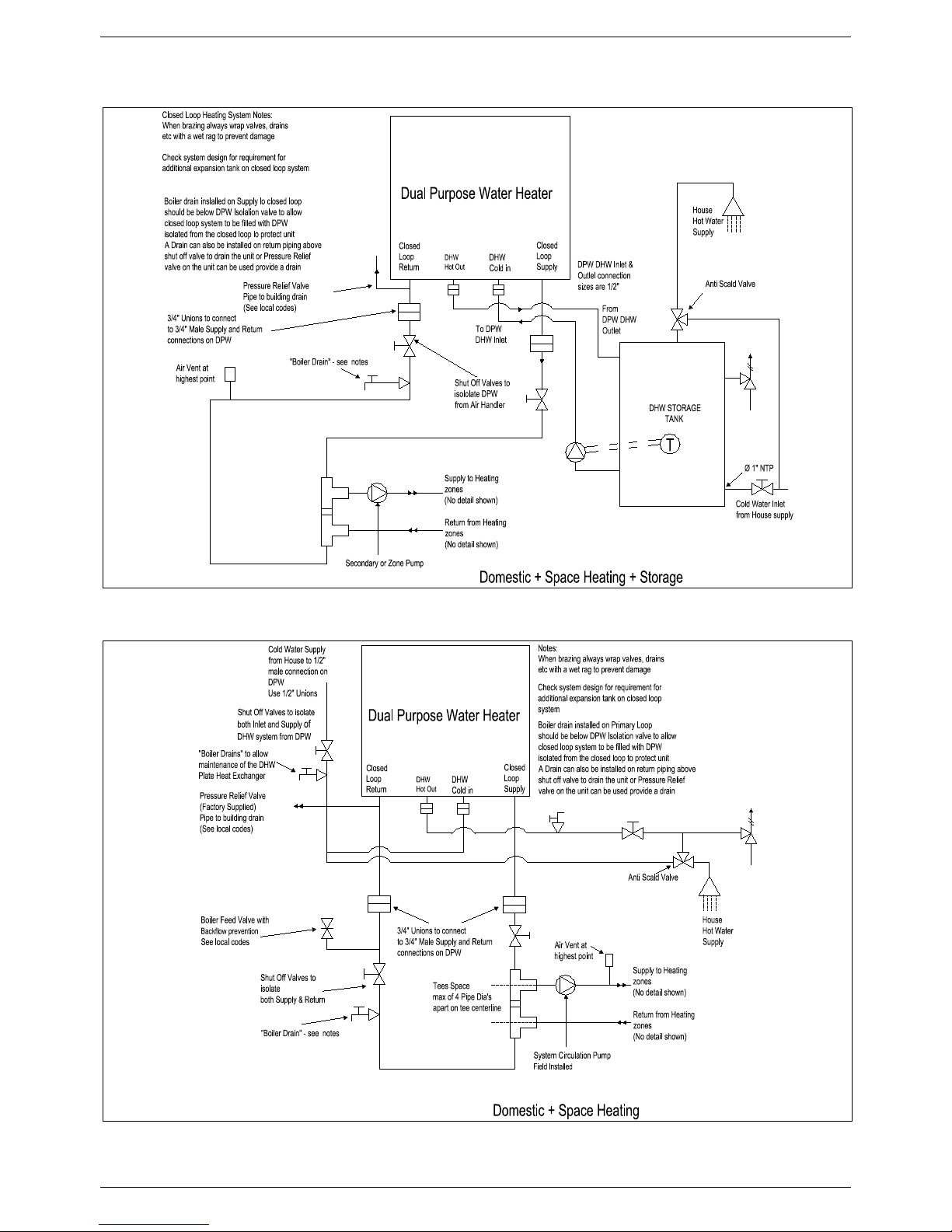
The water heater can be used for potable hot water heating and combination space heating applications.
Note: the following illustrations are c onc eptual designs only. There are many design variations of the equipment
presented. Designers m ust add all necessary saf ety and auxiliary equipment to conform to Code requirement
and proper design practice. For more details, contact the manufacturer or distributors of the products.
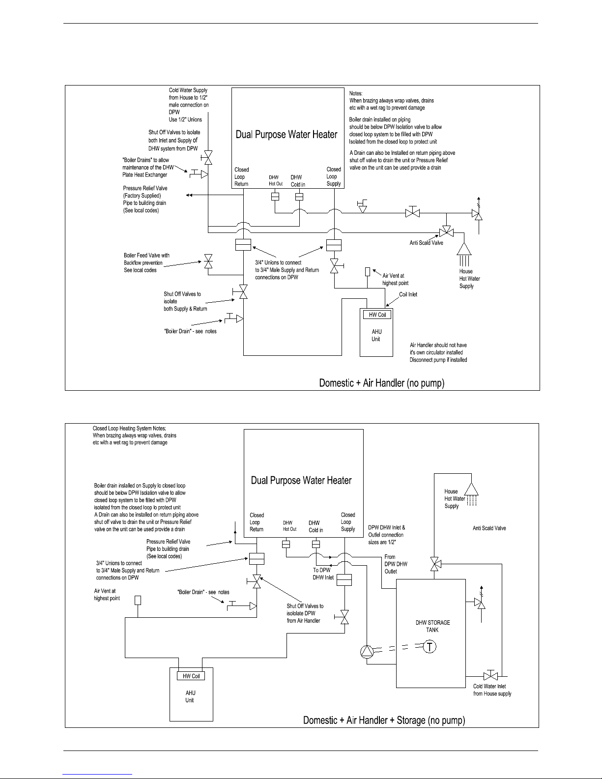
INSTALLATION INSTRUCTIONS
23
3.6 Schematic of Piping Installation
INSTALLATION INSTRUCTIONS
24

INSTALLATION INSTRUCTIONS
25
3.8 Gas Connection
Gas Piping Guidelines
Follow all local codes and/or the most recent edition of the National Fuel Gas Code (ANSI Z223.1/NFPA 54) in
the USA or the Natural Gas and Propane Installation Code in Canada (CAN/CSA B149.1).
Gas Supply Lines Pressures
The minimum and maximum inlet gas pressures are Natural Gas Min. 7.00”WC – Max. 14.00”WC.
Gas press ures over and above the s pecif ied r ange will result in adverse perf or mance and dangerous operating
conditions; any damage resulting from extreme gas supply pressures will not be covered by the limited
warranty.
Until pressure testing of the main gas supply line is completed, ensure the gas line to the FLOWMAX
Combination Water Heater is disconnected to avoid any damage to the water heater.
The appliance and its individual shut off valve must be dis connected fr om the gas supply piping system during
any pressure testing of that system at test pressures in excess of 0.5 psi (3.5 kPa)..
The appliance m ust be isolated from the gas supply piping system by closing its individual manual shut-off
valve during any pressure testing of the gas supply system at test pressures equal to or less that 0.5 psi (3.5
kPa).
The gas appliance and its gas connections must be leak tested before placing the appliance in operation.
Leaks can be found by using a gas leak detection device or by applying soapy water to all gas fittings. Should
bubbles occur, tighten those connections and re-test.
Always purge the gas line for any debris before connecting to the water heater gas inlet.
Never use an open flame to test for gas leaks as property damage, personal injury or death could result.
The maximum inlet gas pressure must not exceed the valve specified by the manufacturer and that the
minimum valve listed as for the purposes of input adjustment.
The connection to the gas supply must be carried out by professionally qualified personnel in accordance with
the relevant standards.
■ Check the internal and external seals of the gas supply system.
■ A gas shut-off valve must be installed upstream of the appliance
■ Before starting up the water heater, mak e sure that the type of gas corresponds to that for which the appliance
has been set-up.
■ The gas supply pressure must be between the values reported on the rating plate.
■ Conversion of the appliance from natural gas to LPG or vice versa must be carried out by qualified personnel.
■ The power supply cable must be replac ed by a qualified electrician. If the cable is damaged in any way, switch
off the appliance and have the cable replaced by a suitably qualified electrician.
When using an electrical appliance, a few fundamental rules must be observed:
• Do not touch the appliance with damp or wet parts of the body or when barefoot.
• Do not pull on the electric wires.
• Do not allow the appliance to be used by children or anyone unfamiliar with its operation.

INSTALLATION INSTRUCTIONS
26
3.9 Electrical connections
General warnings
Follow the electrical code requirements of the local authority having jurisdiction. In the absence of such
requirements, follow the lates t edition of the National Electr ical Code ( NFPA 70) in the U.S. or the lates t edition
of CGA C22.1 Canadian Electrical Code – Part 1 in Canada.
Electric Wiring: Ground and Surges
All units c ome with factory installed 3-pronged (grounded) plug end. T he combination water heater can be
plugged into any standard electrical duplex outlet close to the unit as it requires only 4 Amps.
If the local j urisdiction requires the unit to be wired directly, remove and discard the f actory installed plug. An
ON/OFF switch controlling the main power between the break er and the FLOW MAX W ater Heater should be
provided to facilitate end-user maintenance and servicing. This should be done by a qualified electrician.
The combination water heater must be electrically grounded. Ensure the electrical receptac le, in which the
water heater will be plugged into, is properly grounded; if wiring directly, do not attach the ground wire to either
the gas or the water piping as plastic pipe or dielectric unions may isolate the water heater electrically.
The use of a surge protector is recommended to protect from power surges.
Do not energize elec tric power to the unit until all plumbing and gas piping is complete and the combination
water heater has been filled with water.
The electrical supply required by the water heater is 120VAC at 60Hz with a maximum 4A rating with proper
grounding.
DO NOT connect 220-240VAC and any other voltage to this FLOW MAX Com bination Water Heater. This will
damage the combination water heater and void the warranty.
Do not disconnect the power supply when the unit is in normal operation.
If there is a power failure in cold weather areas, the freeze prevention system in the water heater will not
operate and may result in freezing of the heat exchanger; in cold weather areas where power failures are
common, you m us t c ompletely drain the unit to prevent damage if the power will be off f or any extended period
of time.
Damage caused by freezing is not covered under warranty.
CAUTIO N : Label all wires prior to disconnection when servicing controls. W iring errors can cause improper
and dangerous operation. Verify proper operation after servicing.
The c onnection to the main power supply must be carried out by professionally qualified electrical personnel,
registered in accordance with current legislation and local authorities.
Always check to make sure that the appliance has an efficient ground system. This requirement is only
satisfied if it has been properly connected to an efficient ground system installed in accordance with the
requirements of current safety standards and carried out by professionally qualified personnel.
This basic safety measure must be checked, verified and carried out by professionally qualified electrical
personnel.
Have the electrical system checked by a qualified electrician. The m anufacturer will not be held liable for any
damage or injury caused as a result of an inefficient or faulty ground system.
■ Ensure the domestic power supply is checked by a qualified electrician to ensure that it can support the
maximum power absorption of the appliance, as indicated on the rating plate. In particular, mak e sure that the
cable sizes are adequate for the power absorbed by the appliance;

INSTALLATION INSTRUCTIONS
27
■ The power supply cable must be replaced by a qualified electrician. If the cable is dam aged in any way, switch
off the appliance and have the cable replaced by a suitably qualified electrician;
When using an electrical appliance, a few fundamental rules must be observed:
• Do not touch the appliance with damp or wet parts of the body or when barefoot.
• Do not pull on the electric wires..
• Do not allow the appliance to be used by children or anyone unfamiliar with its operation;
If the unit fails to re-start after any fault, unplug the unit for 30 seconds, then re-plug in the unit and try to restart with the on/off
switch. If the unit fails to restart, call a qualified Technician for service.

INSTALLATION INSTRUCTIONS
28
Remote control connection
Connect the power supply to the terminal board inside the control panel as follows:
a. Switch off the power supply at the main switch.
b. Remove the front case panel of the water heater.
c. Slacken the screws and remove plate A (see fig. 1).
d. With the plate removed, connect the wires to the terminal board B as follows:
• Connect the ground wire (normally coloured green/yellow) to the terminal marked with the ground symbol “
“.
• Connect the neutral wire (normally coloured blue) to the terminal marked with the letter “N”.
• Connect the live wire (normally coloured brown) to the terminal marked with the letter “L”.
• Terminals identified by the letters: Ta ⇒ Room thermostat
Se ⇒ Outside temperature sensor
When the wires have been connected, place plate “A" back to position.
TaL N Ta Se Se
B
A
Fig. 1

INSTALLATION INSTRUCTIONS
29
3.10 Venting
Improper venting of combination water heater can result in excessive levels of car bo n monoxide which
can result in severe personal injury or death. This combination water heater must be vented in
accordance with the “Venting of Equipment” section of the latest edition of the ANSI Z223.1 / NFPA 54
Natural Gas Code and/or the “Venting systems and air supply for appliances” section of the latest
version of the CAN/CSA B149.1 Natural Gas and Propane Installation Code in Canada and in
accordance with all applicable local building codes.
Venting Guidelines
• For best results, keep the vent system as short and straight as possible.
• Locate the combination water heater as close as possible to the vent termination.
• The combination water heater vent must not be common vented with any other gas appliance or vent stack.
• Slope vent upwards towards the vent terminal at a rate of 1/8” per foot (1% slope).
• Vent termination must be a minimum of 12” above grade or expected snowfall.
• Vent and air intake pipe must be supported every 4 feet of horizontal run and every 5 feet of vertical run.
FLOWMAX and Direct Vent
• All FLOWMAX Combination Water Heaters are prepared at the factory to be direct vent (sealed
combustion) units which draw all of their required combustible air directly from outside the building.
• All FLOWMAX Combination W ater Heaters use 2” or 3” diam eter exhaust and 2” or 3” diameter air intake
pipe.
• The air intake vent materials can be made of ABS, CPVC, PVC materials and in accordance with all
applicable local building codes.
Contaminated Make-Up Air Will Damage the Unit
• Recommend not to oper ate the combination water heater in an area that is or will be under construction or
renovation.
• The FLOWMAX warranty will not cover damage and premature wear caused to the unit due to installation in
a contaminated environment.
• All of the exhaust venting connections must be leak check ed with a soap solution upon initial start up of the
water heater. Any leaks must be repaired before continuing operation of the water heater.
• Warranty will not be available if the water heater is used for construction heat.

INSTALLATION INSTRUCTIONS
30
Exhaust Vent Piping Materials
• Use only 2” or 3” solid PVC/CPVC schedule 40 PVC/CPVC or ULC S636 pipe and fittings.
• Venting requirements in USA and Canada are different. Please consult with the mos t recent edition of the
National Fuel Gas Code (ANSI Z223.1 / NFPA 54) or CAN/CSA B-149.1 as well as local codes for
applicable venting regulations and restrictions.
• For installation in Canada, field supplied plastic vent piping must comply with CAN/CSA B-149.1 (latest
edition) and be certified to the standard for type BH Gas Venting Systems, ULC S636 c omponents of this
listed system shall not be interchanged with other vent systems or unlisted pipe/fittings. All plastic
components and specified primers and glues of the certified vent system must be from a single
manufacturer and not intermixed with other system m anufacturer’s vent system parts. The supplied vent
adaptors are certified as part of the combination water heater.
• For all units installed with vertical exhaust, must have an additional approved condensate drain installed on
the Horizontal section of the exhaust vent. Fittings must be ULC S636 approved.
• PVC/CPVC pipe/fittings have been approved for use on this appliance with zero clearance to combustibles.
Intake Vent Pipe Materials
• Solid PVC schedule 40 PVC or ULC S636 pipe and fittings and ABS pipe and fittings can be used for
combustion air intake on FLOWMAX products.
• Transition cement must be used for the ABS pipe connected to the PVC appliance adaptors.
• All plastic components and specified primer s and glues of the certified vent system m ust be from a single
manufacturer and not intermixed with other system manufacturers vent system parts.
Allowable Vent Lengths
Model
Size
Max Equivalent Length
Vertical and Horizontal
per Vent Run
Type
Exhaust Vent
Intake Vent
FLOWMAX-90
2"/3" Diam
100 ft
Natural Gas or LP
Schedule 40 PVC/CPVC
PVC, CPVC or ABS
FLOWMAX-120
3" Diam
100 ft
Natural Gas or LP
Schedule 40 PVC/CPVC
PVC, CPVC or ABS
FLOWMAX-170
3" Diam
100ft
Natural Gas or LP
Schedule 40 PVC/CPVC
PVC, CPVC or ABS
Equivalent Lengths
• Reduce the maximum vent length accordingly for each elbow used.
• Each 2”/3” 45⁰ elbow equates to 2.5 linear feet of vent pipe.
• Each 2”/3” 90⁰ short radius elbow equates to 7.5 linear feet of vent pipe.
• Each 2”/3” 90⁰ long radius elbow equates to 5 linear feet of vent pipe.
• The maximum length listed is for exhaust vent only. The intake length should be equal length.
• The total maximum equivalent vent pipe distance cannot exceed 100f t for horizontal and vertical venting
distance.
• The maximum lengths are not including elbows.
• Exceeding the maximum venting distances will cause the appliance to malfunction or cause an unsafe
condition.
Minimum Vent Lengths
• 3" Diameter - 6" pipe (Iength) plus one elbow.

INSTALLATION INSTRUCTIONS
31

INSTALLATION INSTRUCTIONS
32

INSTALLATION INSTRUCTIONS
33

INSTALLATION INSTRUCTIONS
34

INSTALLATION INSTRUCTIONS
35

INSTALLATION INSTRUCTIONS
36
4. COMMISSIONING THE APPLIANCE
4.1 General warnings
The following operations must be carried out by professionally qualified personnel, registered in
accordance with current legislation.
The water heater leaves the factory pre-set and tested for burning either natural Gas or LPG.
Nevertheless, when startin g the water heater for the first time, make sure that the information on the
rating plate corresponds to the type of gas being supplied to the water heater.
Once th e system has been f illed an d t he n ecessary adjustment s made, remember to tight en the screw s
of the gas valve test point and make sure that there are no gas leaks from the test point and from any
pipe fittings upstream of the gas valve.
■ Preliminary operations
Switching the water heater on for the f irst tim e means check ing that the installation, regulation and operation of the
appliance are correct:
• Check that the rating on the rating plate corresponds to that of the mains supply networks (gas, electricity,
water));
• Check that the power supply voltage to the water heater c omplies with the rating plate (120 V – 60 Hz) and that
the live, neutral and ground wires are connected properly. Also make sure that the ground connection is sound;
• Check that the gas s upply is correctly sized for the flow rate required by the water heater and that it is fitted with
all the safety and control devices stipulated current regulations;
• Check that the supply of combustion air and exhaust and condensate discharge systems are functioning
correctly and in line with current law and national and local standards;
• Check for the presence of permanent aeration/ventilation openings as required by current law for the type of
appliances installed;
• Check that the exhaust vent and its connections to the term ination comply with the requirements of current law
and national and local standards for the type of appliances installed;
• Make sure that any central heating shut-off valves are open;
• Check that the condensate drain system, including outside the water heater (exhaust system condensate
collection devices), allows the condensate to flow freely to the drain.
• Check that there are no flammable materials or liquids in the immediate vicinity of the water heater;
Flush out both primary and domestic hot water circuits (see 4.3 “Flushing the system”).

INSTALLATION INSTRUCTIONS
37
4.2 Filling the system
Check the properties of the water supply and install the
appropriate treatment devices if the mains water has a
hardness rating more than 14.5 gpg (250 mg/L) i
n order
to prevent scaling and eventual damage to the D.H.W
heat exchanger.
Use only clean tap water to fill the system.
A pre-filtering system can be installed on the incoming
water supply to help reduce impurities and limestone.
This water heater must have adequate water flowing
through it whenever the burner is on. Failure to do this
will damage the unit and void the warranty.
Once the water pipes have been connec ted, close the gas feed
valve and fill the system as follows:
• Check that the circulation pump runs freely;
• Check that the plug of the air vent valve has been slac kened
slightly to allow air to escape from the system (fig.1);
• Open the main domestic water supply valve;
• Open the filling tap R (fig. 2);
• Unscrew the plug on the pump to remove any trapped air,
check that the pump is free then re-tighten it when water
starts to flow out (fig.1);
• Before switching on the water heater, purge air completely from
the air vent valve positioned on the top of t he condensing
exchanger (fig. 3);
• Open the air vents on the radiators and monitor the air
evacuation process. When water starts to flow out of the
radiators, close the air vents;
• Use the pressure gauge M (fig. 2), to check that the systems
pressure reaches the middle of the green area (equal to 1,2
bar, see fig. 4).
• On completion, make sure that the filling tap R is
perfectly closed.
1
4
3 bar
1.5 bar
0.5 bar
1.2 bar
GREEN AREA
PUMP PLUG
PUMP
AIR VENT VALVE PLUG
AIR VENT VALVE
M
R
3
2

INSTALLATION INSTRUCTIONS
38
4.3 Flushing the system
Failure to flush and add inhibito r to the system will invalidate the appliance operation.
All systems must be thoroughly drained and flushed out using additives – corrosio n inhibitors and flushing
agents/descalers. All flushing must be done for new and retrofit installs.
Warning: Failure to clean the system and add adequate inhibitor invalidates the warranty
To flush out the primary side of this unit:
a. Fill the water heater with clean water as per the filling instructions.
b. Using a drain off cock on the lowest point of the s ystem allow the water to dr ain from the system and water
heater.
c. In order to f lush the system correctly, turn off all radiators or fan coils. Open the filling loop and drain cock
simultaneously and allow the water to flow through the water heater.
d. Open each individual radiator or fan coil, allowing water to flow through. Then, turn that radiator or f an coil off
and repeat for all radiators or fan coils on the system.
e. T urn off the filling loop and close the drain cock. Open all radiators or fan coils and open the filling to fill the
system.
f. Continue to fill the system until the pressure gauge reaches 14.5 psi (1 bar).
g. Add an inhibitor to the system water to prevent limestone and magnetite deposits from form ing and to protect
the water heater from galvanic corrosion.
h. In areas where freezing might occ ur, an antifreeze (Gycol) may be added to the system water to protect the
system. Please adhere to the specifications given by the antifreeze manufacture. Do not use automotive
silicate based antifreeze. Please observe that the antifr eeze and water mixture does not exceed 40% of the
antifreeze content. Do not use antifreeze other than that specifically made for hot water heating systems.
Advise systems operator/ultimate owner that system is filled with antifreeze.
To flush out domestic hot water circuit:
a. Open all hot water outlets.
b. Turn on inlet group supply so water enters the water heater; leave to fill until water is released from the hot
water outlets. Turn off all hot water outlets.
c. Connect a hosepipe to the cylinder drain cock and open the drain cock.
d. Allow water to flow through the water heater and out of the drain cock.
e. Turn off water supply, disconnect the hosepipe, close the drain cock and refill the water heater.
4.4 Filling the c onde ns a t e t rap
The condensation trap must be pre-filled when
starting the water heater for the first time in order to
prevent flue gases from flowing back through the
trap.
The filling operation is carried out as follows (see fig.
1):
• Remove plug T and fill the trap S three quarters
full with water;
• Replace plug T and connec t the drainpipe P into
a condensate discharge trap conforming to
current legislation;
Attention! It is recommended to clean the
condensate trap, after a few m onths of water heater
operation, to remove deposits/res iduals left after the
first condensate passage within the water heater
new components that may interfere with the correct
operation of the trap itself.
T
S
Fig. 1

INSTALLATION INSTRUCTIONS
39
4.5 Starting up the water heater
Once the system has been filled,
proceed as follows:
• Check that the exhaust flue is free
of obstructions and correctly
connected to the water heater;
• Switch on the power supply to the
water heater;
• Open the gas isolation valve;
• Place switch 1 in the ON position
(see 2.7 “Control Panel”), after a few
seconds the circulating pump will start
to run;
• Use button 6 to set the SUMMER,
WINTER or SUMMER/WINTER
function. The symbols
will light
up (fixed light) to indicate that the
water heater is working;
• T he automatic ignition system will then
light the burner. This operation is
repeated for 3 times. It may however
be necessary to repeat the operation in
order to eliminate all the air from the
pipes. To repeat the operation, wait
approximately three minutes bef ore reattempting to light the water heater. To
reset the water heater Switch off
switch 1 (see 2.7 “Control Panel”) and
switch it back on again and repeat the
lighting procedure;
• With the water heater ignited, if the
system still emits noises, the
operations must be repeated until all
the air has been removed;
• Check the pressure in the system. If
the pressure has fallen, re-open the
filling tap until the code H2O
disappears on the display and the
pressure reaches the middle of the
green area (1,2 bar). On completion,
close the filling tap.
• If t he CO2 value does not corres pond to the specified value, adjust screw V (see fig. 1) on the venturi clock wise
to reduce the CO2 value or anticlockwise to increase it
;
Table n°1
Gas type
CO2 %
Natural Gas - G20
9.3
Liquid Propane Gas - G 31
11
V
Fig. 1
REGULATION INSTRUCTIONS
40
5. REGULATING THE APPLIANCE
5.1 Parameters table
PARAMETER N° TYPE OF OPERATION PARAMETER VALUE FUNCTION
1 Selects the type of water heater
00
01
02
03
Instantaneous (95-140°F)
Water heater with storage tank
B. w/storage tank Comfort (+45°F)
D.H.W. Temperature 95-160 °F
2 Selects the type of gas
00
01
Natural gas
Lpg
3
Sets the central heating
temperature
00
01
Standard (86-167°F)
Reduced (77-104°F )
41
Selects pump mode during
heating phase
00
01
Standard ( 3’ pump overrun)
Permanent (pump runs continuously)
5 Water hammer prevention
00
01
Off
On
6 Central heating timer 00-90 (default = 36)
Delays the heating restart to prevent
frequent On/Offs, Expressed in steps of 5
sec (factory set at 36 x 5 = 180”)
7
Central heating pump overrun
timer
00-90 (default = 36)
The overrun timer can be modified.
Expressed in steps of 5 sec (factory set
at 36 x 5 = 180”)
8 D.H.W pump overrun timer 00-90 (default = 18)
The overrun timer can be modified.
Expressed in steps of 5 sec (factory set
at 18 x 5 = 90”)
9 Minimum gas pressure setting -
Not applicable for FLOWMAX water
heaters
10
Minimum central heating output
setting
-
Not applicable for FLOWMAX water
heaters
11
Maximum gas pressure and
maximum central heating output
setting
-
Not applicable for FLOWMAX water
heaters
12 Ignition sequence setting -
Not applicable for FLOWMAX water
heaters
13
D.H.W priority function (2 min
delay on dhw function)
00
01
Off
On
144
Selects the type of burner
00
01
02
03
Atmospheric (not FLOWMAX)
FLOWMAX 90
FLOWMAX 120
FLOWMAX 170
152
Zone management board
activation
00
01
Off
On
163 Telephone control activation
00
01
Off
On
17 Minimum fan speed setting
60 Hz (Natural Gas)
60 Hz (propane)
To set the minimum frequency value (Hz)
for the fan operation
18 Maximum fan speed setting
155 Hz (Natural Gas)
143 Hz (propane)
To set the maximum frequency value
(Hz) for the fan operation
19
Minimum fan speed setting
(Central Heating)
60 Hz (Natural Gas)
60 Hz (propane)
To set the minimum frequency value (Hz)
for the fan operation in heating mode .
20
Maximum fan speed setting
(Central Heating)
155 Hz (Natural Gas)
143 Hz (propane)
To set the maximum frequency value
(Hz) for the fan operation in heating
mode
21 Ignition sequence setting
90 Hz (Natural Gas)
110 Hz (propane)
To set the fan frequency value (Hz) at the
ignition
22 Fan frequency value display
00
01
Off
On (for 10 min. time)
NOTES:
1 - Activate onl y f or “heat i ng onl y” water heaters;
2 - If the heating s ystem has m ore than one zone, an additional i nterface board (optional extra) must be instal led on the circuit board and
parameter 15 set at 01;
3 - To install t he telephone control, use non-polarised conductors c onnected to contac t TA of the termi nal board in parallel with the remote
control if fitted. Set the parameter 16 at 01.
4- When t he param eter value 01/02/ 03 is s et, param eters from no. 17 to 22 are aut om atic ally ac tivat ed and water heater set ti ngs are c arried -
out in through these parameters (i n Hz) t hat repl ace parameters from no.9 t o no.
Once the parameter value has been set ac cording to the water heater output, the P.C.B will automatically adjust the maximum and
minimum values .
REGULATION INSTRUCTIONS
41
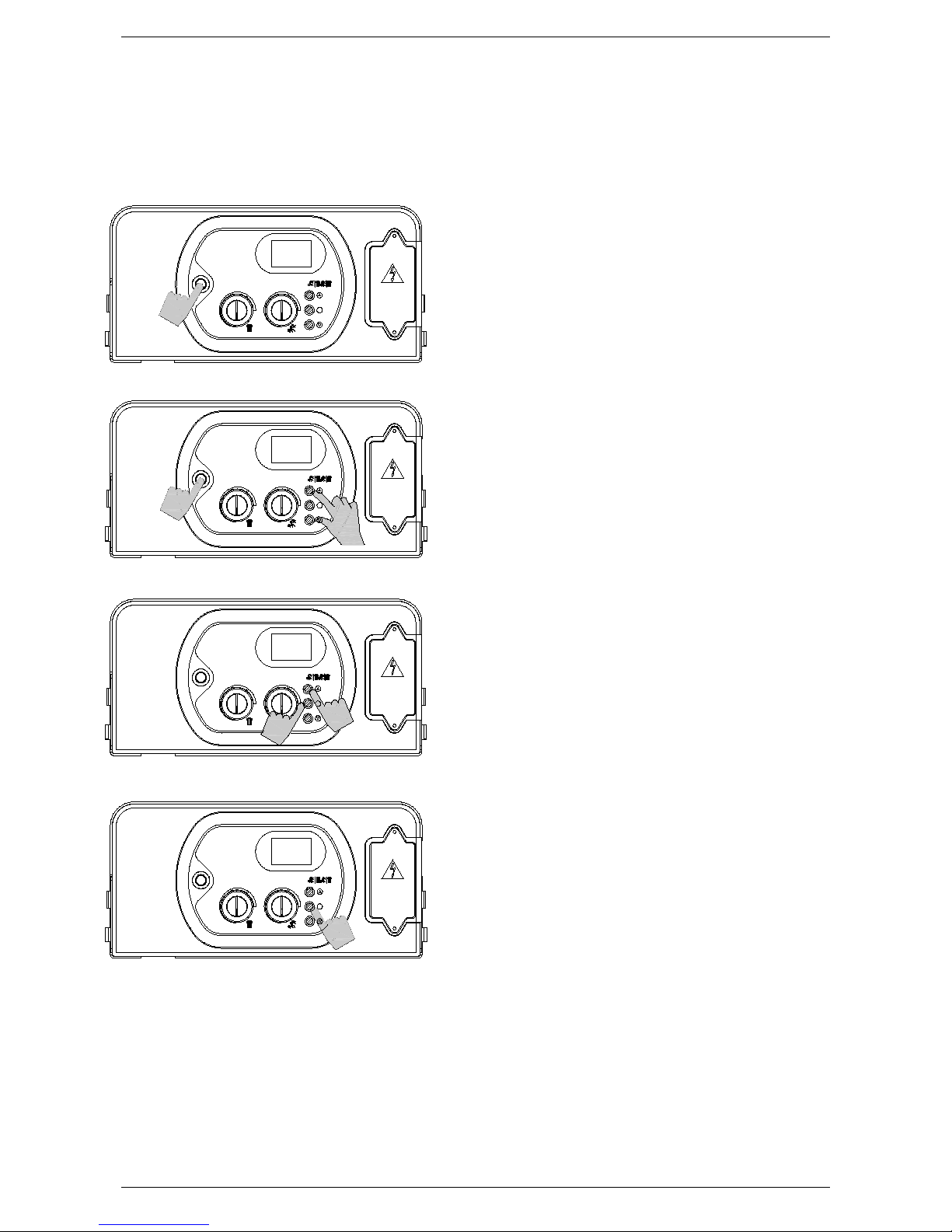
5.2 Setting the parameters
To modify the preset values of the parameters r eported in the previous table, open the paramet er
settings menu as follows:
1. Place the On/Off switch in the OFF
position.
2. Activate the On/Off switch while keeping
buttons ‘+’ and “-“ pressed. W ait for “P 00”
to appear on the display.
3. Release buttons ‘+’ and ‘-’.
4. Keep button ‘S’ pressed and use button ‘+’
and ‘-‘ to select the parameter to modify.
5. Release button ‘S’, then re-press and
release it. The display will indicate the value
of the parameter to modify.
Adjust the value of the parameter using the
procedure described in the following pages.
P 00
S
S
S
S
OFF
P 00
P 01
120V 60Hz
120V 60Hz
120V 60Hz
120V 60Hz

REGULATION INSTRUCTIONS
42
To enter the parameters menu, follow the previously described procedure (steps 1-5).
P
ARAMETER 1 – TYPE OF WATER HEATER
6. Use buttons ‘+’ and ‘-‘ to modify the value of the
parameter:
00 = Instant aneous water heater
01 = Storag e water heat er
02 = Storag e water heat er ‘comfort’ (+ 45 °F)
03 = D.H.W. t emperature 95-160°F
7. Press and release button ‘S’ to confirm. The parameter
number (1) will appear on the display.
8. Switch off the appliance and switch it back on again to
render the new parameter operative.
P
ARAMETER 2 - GAS SUPPLY
6. Use buttons ‘+’ and ‘-‘ to modify the value of the
parameter:
00 = natural gas
01 = propane
7. Press and release button ‘S’ to confirm. The parameter
number (2) will appear on the display.
8. Switch off the appliance and switch it back on again to
render the new parameter operative.
P
ARAMETER 3 – CENTRAL HEATING TEMPERATURE
6. Use buttons ‘+’ and ‘-‘ to modify the value of the
parameter:
00 = standar d ( 86⁰F – 167°F)
01 = reduced (77⁰F – 104°F) for under-floor heat ing
7. Press and release button ‘S’ to confirm. The parameter
number (3) will appear on the display.
8. Switch off the appliance and switch it back on again to
render the new parameter operative.
P 01
S
S
S
S
S
S
00
01
P 02
01
P 03
120V 60Hz
120V 60Hz
120V 60Hz
120V 60Hz
120V 60Hz
120V 60Hz

REGULATION INSTRUCTIONS
43
PARAMETER 4 – CENTRAL HEATING PUMP
6. Use buttons ‘+’ and ‘-‘ to modify the value of the
parameter:
00 = standard (3” overr un)
01 = permanent ( always running)
7. Press and release button ‘S’ to confirm. The parameter
number (4) will appear on the display.
8. Switch off the appliance and switch it back on again to
render the new parameter operative.
P
ARAMETER 5 – WATER HAMMER PREVENTION
6. Use buttons ‘+’ and ‘-‘ to modify the value of the
parameter:
00 = off
01 = on (def ault = 2” )
7. Press and release button ‘S’ to confirm. The parameter
number (5) will appear on the display.
8. Switch off the appliance and switch it back on again to
render the new parameter operative.
P
ARAMETER 6 – CENTRAL HEATING TIMER
6. Use buttons ‘+’ and ‘-‘ to modify the value of the
parameter within the prescribed limits
00 = 0 x 5” = 0”
90 = 90 x 5” = 450” (7.5 m in)
The default value is 36 = 180” = 3 min
7. Press and release button ‘S’ to confirm. The parameter
number (6) will appear on the display.
8. Switch off the appliance and switch it back on again to
render the new parameter operative.
P 04
S
S
S
S
S
S
00
01
P 05
36
P 06
120V 60Hz
120V 60Hz
120V 60Hz
120V 60Hz
120V 60Hz
120V 60Hz

REGULATION INSTRUCTIONS
44
PARAMETER 7 – CENTRAL HEATING PUMP OVERRUN TIMER
6. Use buttons ‘+’ and ‘-‘ to modify the value of the
parameter within the prescribed limits
00 = 0 x 5” = 0”
90 = 90 x 5” = 450” (7.5 m in)
The default value is 36 = 180” = 3 min
7. Press and release button ‘S’ to confirm. T he parameter
number (7) will appear on the display.
8. Switch off the appliance and switch it back on ag ain to
render the new parameter operative.
P
ARAMETER 8 – D.H.W PUMP OVERRUN TIMER
6. Use buttons ‘+’ and ‘-‘ to modify the value of the
parameter within the prescribed limits
00 = 0 x 5” = 0”
90 = 90 x 5” = 450” (7.5 m in)
The default value is 18 = 90” = 1.5 min
7. Press and release button ‘S’ to confirm. T he parameter
number (8) will appear on the display.
8. Switch off the appliance and switch it back on ag ain to
render the new parameter operative.
P
ARAMETER NO. 9 – MINIMUM GAS PRESSURE SETTING
Not applicable for FLOWMAX burner (only for atmospheric burner)
P
ARAMETER NO.10 – MINIMUM CENTRAL HEATING OUTPUT SET T ING
Not applicable for FLOWMAX burner (only for atmospheric burner)
P
ARAMETER NO.11 – MAXIMUM GAS PRESSURE AND MAX. CENTRAL HEATING OUTPUT SETTING
Not applicable for FLOWMAX burner (only for atmospheric burner)
P
ARAMETER NO.12 – IGNITION SEQUENCE SETTING
Not applicable for FLOWMAX burner (only for atmospheric burner)
P 07
S
S
S
S
36
18
P 08
120V 60Hz
120V 60Hz
120V 60Hz
120V 60Hz

REGULATION INSTRUCTIONS
45
PARAMETER 13 – D.H.W PRIORITY
6. Use buttons ‘+’ and ‘-‘ to modify the value of the par am et er:
00 = off
01 = on (def ault = 120” )
7. Press and release button ‘S’ to confirm. The parameter number
(13) will appear on the display.
8. Switch off the appliance and switch it back on again to render the
new parameter operative.
P
ARAMETER 14 – TYPE OF BURNER
6. Use buttons ‘+’ o ‘-’ to modify the value of the parameter:
00 = water heater with atmospheric burner;
01 = water heater with FLOWMAX - 90
02 = water heater with FLOWMAX - 120;
03 = water heater with FLOWMAX - 170;
7. Press and release button ‘S’ to confirm. The parameter number (14)
will appear on the display.
8. Switch off the appliance and switch it back on again to render the
new parameter operative.
P
ARAMETER 15 – ZONED SYSTEM
6. If the system is f itted with zone valves, set the parameter at ‘01’. If
a remote control is installed, an extra interface board must be
installed to control the zone valves. Then set the parameter at ‘01’.
7. Press and release button ‘S’ to confirm. The parameter number
(15) will appear on the display.
8. Switch off the appliance and switch it back on again to render the
new parameter operative.
P
ARAMETER 16 – TELEPHONE CONTROL
6. If a telephone interface is installed, enable the board by setting
parameter 16 at ‘01’;
7. Press and release button ‘S’ to confirm. The parameter number
(16) will appear on the display.
8. Switch off the appliance and switch it back on again to render the
new parameter operative.
N.B.: The connection of the telephone interface to contact TA of the
terminal board must be wired in parallel with the r emote control using
two non-polarised conductors.
S
S
S
S
P 14
02
S
S
00
P 15
00
P 16
01
P 13
S
S
120V 60Hz
120V 60Hz
120V 60Hz
120V 60Hz
120V 60Hz
120V 60Hz
120V 60Hz
120V 60Hz

REGULATION INSTRUCTIONS
46
PARAMETER 17 – MINIMUM FAN SPEED SETTING
6. Use buttons ‘+’ o ‘-’ to modify the value of the parameter between: min
= 33 Hz ; max = value of parameter 18
The default value is :
- 60 Hz for Natural Gas;
- 60 Hz for propane;
7. Press and release button ‘S’ to confirm. The parameter number (17)
will appear in the display.
8. Switch off t he appliance and switch it back on again to render the
new parameter operative.
P
ARAMETER 18 – MAXIMUM FAN SPEED SETTING
6.
Use buttons ‘+’ o ‘-’ to modify the value of the parameter between:
min
= value of parameter 17; max = 202 Hz.
The default value is:
- 155 Hz for Natural Gas;
- 143 Hz for propane;
7. Press and release button ‘S’ to confirm. The parameter number (18)
will appear in the display.
8. Switch off t he appliance and switch it back on again to render the
new parameter operative.
P
ARAMETER 19 – MINIMUM FAN SPEED SETTING
C
ENTRAL HEATING MODE
6. Use buttons ‘+’ o ‘-’ to modify the value of the paramet er between:
min = 33 ; max = value of parameter 18.
The default value is:
- 60 Hz for Nat ur al G as ;
- 60 Hz for propane;
7. Press and release button ‘S’ to confirm. The parameter number (19)
will appear in the display.
8. Switch off t he appliance and switch it back on again to render the
new parameter operative.
P
ARAMETER 20 – MAXIMUM FAN SPEED SETTING
C
ENTRAL HEATING MODE
6. Use buttons ‘+’ o ‘-’ to modify the value of the parameter bet ween:
min = value of parameter 17; max = 202 Hz.
The default value is:
- 155 Hz for Natural Gas;
- 143 Hz for propane;
7. Press and release button ‘S’ to confirm. The parameter number (20)
will appear in the display.
8. Switch off t he appliance and switch it back on again to render the
new parameter operative.
S
S
P 17
055
P 20
164
P 19
055
S
S
164
P 18
S
S
S
S
120V 60Hz
120V 60Hz
120V 60Hz
120V 60Hz
120V 60Hz
120V 60Hz
120V 60Hz
120V 60Hz

REGULATION INSTRUCTIONS
47
PARAMETER 21 – IGNITION SEQUENCE SETTING
6. Use buttons ‘+’ o ‘-’ to modify the value of the
parameter between: min = value of par ameter 17; max
= value of parameter 18.
The default value is:
- 90 Hz for Nat ur al G as ;
- 110 Hz for propane;
7. Press and release button ‘S’ to confirm. The parameter
number (21) will appear in the display.
8. Switch of f the appliance and switch it back on again to
render the new parameter operative.
P
ARAMETER 22 – FAN FREQUENCY VALUE DISPLAY
6. Use buttons ‘+’ o ‘-’ to modify the value of the parameter:
- 00 = Off
- 01 = On
If parameter value 01 is selected, during the water heater
operation, the display will show the fan frequency value
for 10 min.
7. Press and release button ‘S’ to confirm. The parameter
number (22) will appear in the display.
8. Switch of f the appliance and switch it back on again to
render the new parameter operative.
P 21
S
S
S
S
110
00
P 22
120V 60Hz
120V 60Hz
120V 60Hz
120V 60Hz
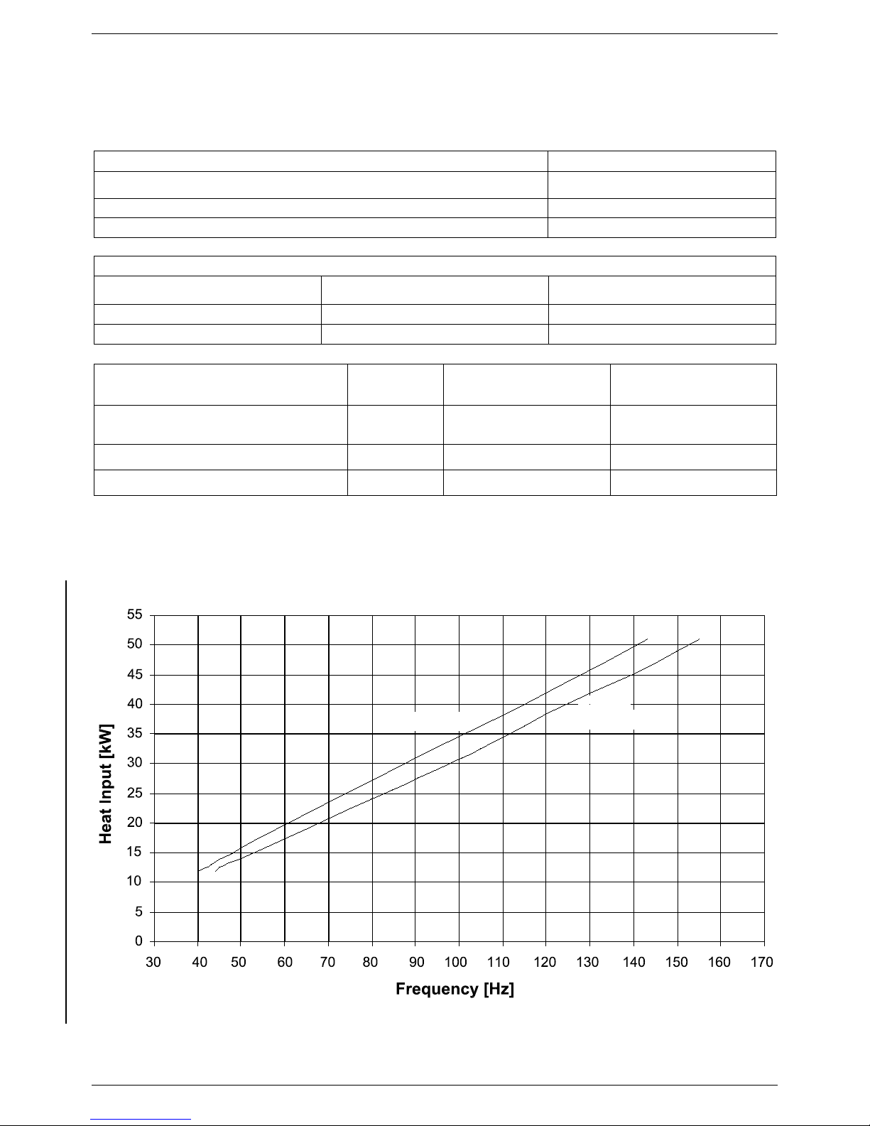
REGULATION INSTRUCTIONS
48
5.3 Gas data
Technical data tables
Table no.3 - Gas data table
NATUR AL GAS G20
LIQUID PROPANE GAS
G31
Lower Wobbe Index
(59°F; 14.5 psi)
MJ/Nm3 45.67 70.69
Nominal supply gas pressure
mbar - psi
20 - 0.29
37 - 0.537
Consumption (59°F; 14.5 psi)
ft3/hr
190.7
73.10
Heating Power (kW) – Fan frequency (Hz) diagram
L.P.G. (G31)
Natural
gas - G20
Table no.1 - CO
2
Values
Gas type CO2 %
Natural gas - G20
9.3
Liquid Propane Gas - G 31
11
Table no.2 - Frequency
Gas type Minimum (Hz) Maximum (Hz)
Natural gas - G20
60
155
Liquid Propane Gas - G 31
60
143

MAINTENANCE INSTRUCTIONS
49
5.4 Regulating the gas valve offset
i
T
-
p
+
tp v
Fig. 1
Fig. 2
Fig. 3
Fig. 4
When replacing the gas valve, it is necessary to regulate
the offset on the new gas valve to guarantee a correct
operation of the water heater.
Instructions as follows:
Fig. 1 – Disconnect the silicon pipe from its connection i
onto the venturi air intake point.
Fig. 2 – Connect that end of the silicon pipe to a ‘T’
connection
T
and bring the end of another silicon pipe from
the same ‘T’ connection to the venturi air intake point
i
.
Insert a third silicon pipe on the free connection of the ‘T’
and connect its end to the negative point
-
of a gas
pressure manometer.
Fig. 3 – Unscrew the pres sure
p
point screw and connect
there the pipe that goes to the positive point
+
of the gas
pressure manometer.
Switch the water heater On at the minimum power. The
manometer should read a value of
-
0.04 mbar
; if you read
a different value, proceed as follows (Fig.4)
Fig. 4 – Rem ove the protection cover tp of the
gas valve and adjust plastic screw
v
with a
screwdriver to modify the value on the
manometer and to bring it to
-
0.04 mbar
.
Once the regulation is completed, disconnect
pipes and restore original water heater
configuration.

MAINTENANCE INSTRUCTIONS
50
6. MAINTENANCE (authorized personnel)
6.1 General War nings
All maintenance operations must be carried out by professionally qualified personnel, authorized by
FLOWMAX.
The frequency of water heater maintenance is recommended to be carried out once a year.
In order to guarantee the long life of the appliance and in accordance with the current gas safety
regulations, only us e original spare parts
Before carrying out any type of maintenance operation, disconnect the appliance from the electrical
supply and shut off the gas valve.
Warranty will not be offered if recommended maintenance is not followed.
6.2 Maintenance
Periodic examination of the entire venting system is recommended. Make sure all the venting
connections/joints are tight and in go od condition where visible.
Clean the burner cylinder using a non-metal brush and without damaging the ceramic fibre.
Clean the heat exchanger using a recommended detergent from FLOWMAX Technologies for the
stainless steel. Do not wet the ceramic fibre coating.
Visually inspect the burner flame. The flame must burn with a clear blue, stable flame. If the burner
flame appearance is not satisfactory or debris is visible on the burners, remove and clean with a
vacuum cleaner.
All electric motors are permanently lubricated and do not need oiling. Remove the combustion air
blower and clean wheel and housing with soft brush or vacuum.
Verify proper operation after any servicing.
Wipe the outside surface with a wet cloth; then dry the surface. Use a neutral detergent to clean any
stains.
Vent termination should be inspected for blockage during maintenance checks.
Check for blockage at the drain pipe and condensate trap.
Clean condensate trap and check for correct level of water.
Check for water leaks from the equipment and piping.
Warranty will not be offered if recommended maintenance is not followed.
6.3 Water heater inspection
In order to ensure that the water heater operates efficiently and safely, it is recomm ended that the appliance is
inspected by a suitably competent technician at least once a year.
The following operations should be carried out annually
■ Check the condition of the gas seals and replace where necessary.
■ Check the condition of the water seals and replace where necessary.
■ Visually inspect the condition of the combustion chamber and flame.
■ When required, check that the com bustion is correctly regulated and if necessary proceed in line with section
“Commissioning the water heater”.

MAINTENANCE INSTRUCTIONS
51
■ Remove and clean any oxidation from the burner.
■ Check that the seal of the room-sealed chamber is undamaged and positioned correctly.
■ Check the primary heat exchanger and clean if necessary.
■ Check the maximum and minimum modulation pressures and the modulation itself.
■ Check the c ondition and operation of the ignition and gas safety systems. If necessary, rem ove and clean the
scaling from the ignition and flam e detect ion electrodes, paying particular attention to replace them at the c orr ect
distance from the burner.
■ Check the heating safety systems: temperature limit safety thermostat, pressure limit safety device.
■ Check the pre-fill pressure of the expansion vessel (see expansion vessel data plate).
■ For safety reasons, periodically check the integrity and operation of the exhaust system.
■ Check that the connection to the mains electricity supply complies with that reported in the water heater’s
instruction manual.
■ Check the electrical connections inside the control panel.
■ Check the D.H.W flow rate and temperature.
■ Check that the condensate drain system is working cor rectly, including any parts of the system outside the water
heater such as condensate collection devices along the length of the flue and/or any acid neutralising devices.
■ Check that the condensate flows freely and that there are no exhaust fumes present within the appliance.
Warranty will not be offered if recommended maintenance is not followed.

MAINTENANCE INSTRUCTIONS
52
6.4 Accessing the water heater
All maintenance operations require one or
more of the water heater casing panels to
be removed.
The side panels can only be removed
after the front panel has been removed.
Front panel:
Remove the fixing screws at the lower
edge of the front panel.
Grasp the lower part of the panel and
pull it outwards
(fig. 1) and then
up.
Left and right side panel:
Remove the fixing screws at the f ront
and lower edge of the side panel to
remove.
Grasp the bottom of the panel, m ove
it sideways and then upwards to
remove it
.
To access the electrical connections
of the control panel, proceed as
follows:
• Remove the front panel (see fig. 1).
• Grasp the left and right control panel
support brackets
and pull them
outwards, at the sam e time rotating the
panel downwards.
• Unscrew the four fixing screws
and
remove the cover.
6.5 Flushing out the primary side
• Fill the water heater as per the filling instructions.
• Using a drain off cock on the lowest point of the system allow the water to drain from the system and water
heater.
• In order to flush the system correc tly, turn of f all radiators or fan coils. Open the filling loop and drain cock
simultaneously and allow the water to flow through the water heater.
• Open each individual radiator or fan coil, allowing water to flow through. Then turn that radiator or f an coil off
and repeat for all radiators or fan coil on the system.
• Turn off the filling loop and close the drain cock open all radiators and open the filling to fill the system.
• Continue to fill the system until the pressure gauge reaches 14.5 psi (1.0 bar).
Fig. 1
2
4
3
5

MAINTENANCE INSTRUCTIONS
53
6.6 Draining the central heating system
If the need arises to drain the system, this can be
done as follows:
• Switch the system to “W INTER” mode and ignite
the water heater.
• Switch off the power supply to the water heater.
• Wait for the water heater to cool down.
• Connect a hosepipe to the system drain point R
and locate the other end of the hose in a suitable
drainage system.
• Open the system drain valve (fig. 1).
• Open the air vents on the radiators, starting with
the highest and moving down the system to the
lowest.
• When the system has been drained, close the
radiator breather valves and the drain valve.
• If only the water heater needs to be drained,
close the flow/return isolating valves on the heating circuit and open the drain valve R located at the
bottom of the water heater on the pump manifold (see fig. 1 );
Draining the domestic hot water system
If there is a danger of freezing, the domestic hot water system should be drained. This can be done as follows:
• Close the mains water supply valve.
• Open all the hot and cold water taps.
• On completion, close all the previously opened taps.
R
Fig. 1

MAINTENANCE INSTRUCTIONS
54
6.7 Maintenanc e ope rations
Before carrying out any cleaning or part
replacement operations, ALWAYS turn off
the ELECTRICITY, WATER and GAS
supplies to the water heater.
FLOWMAX will not be held responsible for
damage to any of the water heater’s
components caused by non-compliance
with this instruction.
For all maintenance operations requiring removal of
the water heater casing, r ef er to the pr ocedur es
described in paragraph 6.3 “Accessing the
water heater”.
Cleaning the main exchanger module and
combustion unit (fig. 1)
• Disconnect the electrical connections of the
electric fan.
• Disconnect the joint and remove the pipe linking
the gas valve to the injector unit (venturi).
• Disconnect the joint and rem ove the gas feed pipe
from the gas valve.
• Un-plug the ignition electrode and f lame detection
wires from the ignition control unit.
• Unscrew the ring-nut at the bottom of the room-
sealed chamber and remove the gas valve.
• Unscrew the nuts securing the burner unit
(consisting of a fan, manifold and burner) to the
primary heat exchanger.
• Rem ove the burner unit, paying particular attention
not to remove the ceramic fibre protect ion from the
bottom of the heat exchanger.
• Check that the burner is not affected by deposits,
scaling or excessive oxidation. Check that all the
holes in the burner are free.
• Clean the elec trodes carefully without altering their
positions with respect to the burner.
• Clean the burner c ylinder using a non-metal brush
and without damaging the ceramic fibre.
• Check the integrity of the gasket on the cover of
the burner.
• Clean the heat exchanger using a recommended
detergent from FLOWMAX Technologies for
stainless steel, distributing the product on the
spirals of the exchanger using a brus h. Do not wet
the ceramic f ibre coating. W ait a f ew minutes then
remove the deposits using a non-metal brush.
Then remove the residues under running water.
• Remove the pipe clip, remove the condensate
drainpipe and clean under running water.
• Unsc rew the joint to the condensate trap, remove
the trap and wash under running water.
• With the cleaning completed, re-assemble the
components following the above procedure in
reverse order.
Finally, check the water heater to make sure that all
gas and exhaust joints are tight.
Primary
heat
exchanger
flue
connection
chamber
Fig. 2
stainless steel
pipe coil
Ceramic fibre
gasket
Fig. 1
Premix burner unit
burner
ignition electrode
ionization electrode
primary heat
exchanger

MAINTENANCE INSTRUCTIONS
55
Cleaning the D.H.W heat exchanger
(see fig. 1)
• Close the shut-off valve and drain the domestic hot
water circuit and central heating circuit of the water
heater;
• Disconnect the joints securing the heat exchanger to
the pipes;
• Unscrew the screws joining heat exchanger fixing
bracket to its support and remove it;
• Remove the heat exchanger;
• De-scale the heat exchanger by chemically washing
the plates;
• Fit new washers;
• Re-assemble the heat exchanger and components
following the above procedure in reverse order;
• Fill the system with water and check for any leaks from
the joints.
Part replacement:
Ignition and/or flame ionization electrodes
(see fig. 2)
• Un-Plug the electrode wires;
• Slacken the fixing screws;
• Remove the electrodes. When fitting the new ones,
check that the seals are not damaged. Replace if
necessary;
• Reconnec t the wires and re-ass emble the c omponents
following the above procedure in reverse order;
• Switch on the power supply and restart the appliance;
If the water heater does not restart, check the
positions of the electrodes (especially the ignition
electrode). Make sure that original position and
distances between the electr odes and the burner are
respected to avoid a water heater malfunction).
Fig. 2
ionization
electrode
ignition
electrode
Fig. 1
D.H.W heat
exchanger
fixing
nuts
washers
fixing
bracket
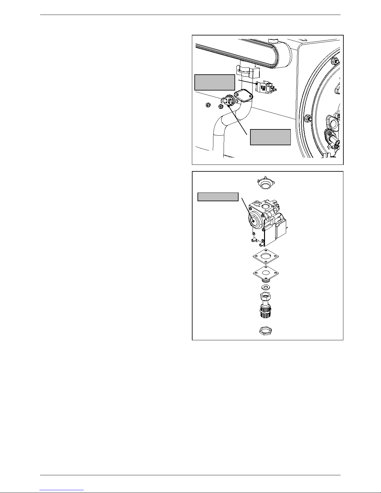
MAINTENANCE INSTRUCTIONS
56
Safety thermostat (see fig. 1)
• Disconnect the connecting wire;
• Unscrew the fixing screws and remove the
thermostat;
• Replace the thermostat and re-assemble the
components following the above procedure in
reverse order;
• Switch on the electricity, water and gas supplies and
restart the appliance.
Heating sensor (see fig. 1)
• Un-Plug the connecting wire;
• Replace the sensor and re-assemble the
components following the above procedure in
reverse order;
• Switch on the electricity, water and gas supplies,
open the shut-off valves and fill the central heating
circuit. Then restart the appliance, remembering to
discharge any air that may be trapped in the system;
Gas valve
(see fig. 2)
• Unsc rew the screws connecting the gas valve to the
venturi.
• Disconnect the gas feed pipe and valve ring-nut at
the bottom of the room-sealed chamber.
• Remove the flanged elbow coupling of the existing
valve and fit it to the new valve; also fit a new cork
washer and a new rubber gasket.
• Replace the gas valve and re-assemble the
components following the above procedure in
reverse order.
• Replace all the gas seals.
• Fully tighten the gas connections.
• Switch on the electricity, water and gas supplies and
check for any gas leaks using a soapy solution or
leak detector spray;
gas valve
Fig. 2
heating
sensor
safety
thermostat
Fig. 1

MAINTENANCE INSTRUCTIONS
57
Electric fan (see fig. 1)
• Remove and dismantle the entire burner unit (see
“Cleaning the burner unit”).
• Use an 8 mm wrench to unscrew the four nuts
securing the electric fan to the gas manifold and then
remove the electric fan, noting the positions of the
washer.
• Remove the air intake duct, unscrew the two fixing
screws from the venturi and remove the electric fan,
paying particular attention not to damage the cork
gasket.
• Replace the electric fan and re-assemble the
components following the above procedure in reverse
order.
• Switch on the electricity, water and gas supplies and
check the soundness of the j oint by measuring the CO
2
levels;
D.H.W heat exchanger (see fig. 2)
•
Close the shut-off valve and drain the domestic hot
water circuit and central heating circuit of the water
heater.
• Disconnect the joints securing the heat exchanger to
the pipes.
• Unscrew the screws joining heat exchanger fixing
bracket to its support and remove it.
• Remove the heat exchanger.
• Fit new washers.
• Replace the heat exchanger and re-assemble the
components following the above procedure in reverse
order.
• Switch on the electricity, water and gas supplies, fill the
system with water and check for any leaks from the
joints.
Circulating pump
(motor body) (see fig. 3)
• Close the s hut-off valves and drain the central heating
circuit of the water heater;
• Use a 5 mm Allen key to unscrew the four screws
securing the motor body to the impeller body;
• Rem ove the motor body and check the condition of the
washer. If necessary, replace the washer;
• Replace the circulation pump and re-assemble the
components following the above procedure in reverse
order;
• Switch on the electricity, water and gas supplies and fill
the system with water. Check for any leaks from the
joints and bleed off any air from the circ uit. Restart the
water heater.
venturi
electric fan
Fig. 1
Fig. 2
D.H.W.heat
exchanger
fixing
nuts
washers
fixing
bracket
Fig. 3
circulating
pump

MAINTENANCE INSTRUCTIONS
58
Diverter valve (see fig. 1)
Replacing the motor
• Unscrew the fixing screws securing the transparent
cover of the diverter valve and remove the cover;
• Unscrew the two motor fixing screws and disconnect
the wires;
• Replace the motor and re-assemble the components
following the above procedure in reverse order;
• Replace the motor and re-assemble the components
following the above procedure in reverse order;
Replacing the diverter valve
• Close the s hut-off valves and drain the central heating
circuit of the water heater;
• Disconnect the joints securing the valve to the pipes;
• Replace the valve body and re-assemble the
components following the above procedur e in reverse
order;
• Switch on the electr icity, water and gas supplies and fill
the system with water. Check for any leaks from the
joints and bleed off any air from the circ uit. Restart the
water heater.
Modulation circuit board (see fig. 2-3)
• Open the control panel (see 6.4 “Accessing the water
heater”);
• Disconnect all the connectors, remove the
regulating knobs, unscrew the four fixing screws and
remove the modulation circuit board;
• Replace the circuit board and re-assemble the
components following the above procedure in reverse
order;
• Switch on the electricity, water and gas supplies
and regulate the water heater (see 5.3 “Gas data”);
The preset parameters of the printed circuit
board correspond to an instantaneous type
water heater fed by natural gas. W hen replacing
the modulation circuit board, check the
“Minimum heating flow rate” – Parameter 19 and
“Max Heating power” – Parameter 20.
Electric fan circuit board (see figs. 2-3)
• Open the control panel (see 6.4 “Accessing the water
heater”);
• Disc onnect the two connectors from the circuit board,
unscrew the two fixing screws and remove the board;
• Replace the circuit board and re-assemble the
components following the above procedur e in reverse
order;
• Switch on the electricity, water and gas supplies.
electric fan circuit board
modulation circuit board
Fig. 2
electric fan circuit board
modulation circuit board
Fig. 3
diverter valve motor
Fig. 1

MAINTENANCE INSTRUCTIONS
59
Primary heat exchanger (see fig. 1)
• Close the shut-off valves and drain the central
heating circuit of the water heater;
• Switch off the power and gas supply to the water
heater;
• Rem ove and dismantle the entire burner unit (see
“Cleaning the condensation module and burner
unit”);
• Remove the gas valve;
• Remove the spring and then the condensate
drainpipe;
• Remove the fixing springs and then the delivery
and return pipes;
• Rem ove the s upport brac kets and pull out the heat
exchanger;
• Remove the regulation sensor from the old heat
exchanger and refit it together with the two
condensate drainpipes to the new one;
• Replace the heat exchanger and re-assemble the
components following the above procedure in
reverse order;
• Switch on the electricity, water and gas supplies
and fill the system with water. Check for any leaks
from the joints and bleed off any air from the
circuit. Restart the water heater, making sure that
there are no gas leaks;
Expansion vessel
(see fig. 2)
• Close the shut-off valves and drain the central
heating circuit of the boiler.
• Use a 19 mm spanner to unscrew the pipe
coupling to the vessel.
• Unscrew the fixing screws and rem ove the upper
mounting bracket. Remove the expansion vessel
from the left side of the boiler.
• Replace the expansion vessel and re-assemble the
components following the above procedure in
reverse order.
• Switch on the electricity, water and gas supplies
and fill the system with water. Check for any leaks
from the joints and bleed off any air from the
circuit;
primary heat
exchanger
flue connection
chamber
stainless steel
pipe coil
ceramic fibre
washer
Fig. 1
B
A
A
B
fixing bracket
expansion vessel
Fig. 2

INSTALLATION INSTRUCTIONS
60
6.8 Wiring diagr a m s
M7
M5
M9
M4M6
M2
1
23456678
M1
1234561234567
1
2
3
4
1
2 3 4
5 6
5
4
M10
321
Zone valve management +
option remote controller board
Zone valve
contact closure
remote controller
zone valve
Telephone control
Remote control
VG
(option)
Storage cylind er timer
brown
VD
SE
EV2
EV1
MF
SSSRIG
TF
TS
C
C
M4
M8
M10
M9
M7
M6
M3
M2M1
M5
+
PRINTED CIRCUIT BOARD DIGITECH - SM20021
EXHAUST FAN
type RG 128
N
L
yellow/green
fusibile 2A
brown
brown
light-blue
green
light-blue
brown
orange
orange
light-blue
light-blue
brown
light-blue
black
red
black
orange
orange
Heating
D.H .W.
brown
brown
brown
black
black
light-blue
orange
black
light-blue
light-blue
brown
black
black
light-blue
black
PA
Key
IG: Main Switch
PA: Air Pressure switch
TS: Safety thermostat
TF: Thermo Fuse 216°F
SR: Heating sensor
SS: DHW sensor
EV: Fan
SE: Outside temperature sensor (optional)
ER: Ionization electrode
EA: Ignition electrode
TRA: Ignition transformer
VD: 3-way valve
C: Circulating pump
MF: Flowswitch micro
PACQ: Water pressure switch
VG: Electronic gas valve
OPTIONAL
M3
PRINTED CIRCUIT BOARD
KOND DT - SK11003
COD. 76702LA
M8

INSTALLATION INSTRUCTIONS
61
Connecting the room thermostat (Option)
Connect the wires to the terminal board inside the instrument panel as follows:
(Example with WEEK digital weekly chronostat):
a. switch off the power supply at the main switch.
b. remove the front case panel of the water heater.
c. slacken the screws and remove plate A (see fig.1).
d. remove jumper TA -TA from the terminal board B;
e. connect the room thermostat/chronostat wires;
When the wires have been connected, place plate “A" back to position and then the front case panel.
Connecting the outside temperature sensor (Option)
Connect the wires to the termi n al board inside the instrument panel as follows:
a. switch off the power supply at the main switch.
b. remove the front case panel of the water heater.
c. slacken the screws and remove plate A (see fig.1).
d. connect the outside temperature sensor on contacts marked as SE-SE on the terminal board B ;
When the wires have been connected, place plate “A" back to position and then the front case panel.
Ta
B
L N Ta Se Se
1
M1
2
A
CHRONOSTAT
Outside
temperature sensor
Fig. 1

INSTALLATION INSTRUCTIONS
62
REMOTE "OPEN THERM"
A
SeSe
TaNL
B
Ta
Outside
temperature
sensor (option)
Ta
B
L
N Ta
Se Se
A
REMOTE "OPEN THERM"
Telephone control
Connecting the remote controller the outside te m perature sensor (option)
Connect the wires to the terminal board
inside the instrument panel as follows:
a. switch off the power supply at the main
switch.
b. remove the front case panel of the water
heater.
c. slacken the screws and remove plate A
(see fig.1).
d. remove jumper TA-TA from the terminal
board B;
e. connect the remote controller wires;
f. connect the outside temperature sensor on
contacts marked as SE-SE on the terminal
board B.
When the wires have been connected, place plate “A" back to position and then the front case panel.
Connecting the remote controller and the tel ephone control (option)
Connect the wires to the termi n al board inside the instrument panel as follows:
a. switch off the power supply at the main
switch.
b. remove the front case panel of the water
heater.
c. slacken the screws and remove plate A
(see fig.1).
d. remove jumper TA-TA from the terminal
board B;
e. connect the remote controller and the
telephone control wires;
f. Active the telephone control through the
parameter no.16 (see 5.1 “Parameters
Table”)
When the wires have been connected, place
plate “A" back to position and then the front
case panel.
Fig. 2
Fig. 1

INSTALLATION INSTRUCTIONS
63
Outside
temperature
sensor (option)
Terminal block
REMOTE "OPEN THERM"
Zone valve management +
option remote controller board
Remote control and zone valves wiring
For the installation of a zone valve p.c.b, it is necessary to access the main p.c.b for electrical connection (see 6.3
“Accessing the water heater”) and to activate the parameter no. 16 (see 5.1 “Parameters table”).

INSTALLATION INSTRUCTIONS
64
REMOTE "OPEN THERM"
Telephone control
Terminal block
Outside
temperature
sensor (option)
Zone valve management +
option remote controller board
Remote control, zone valves and telephone control wirings

INSTALLATION INSTRUCTIONS
65
Regulating the Flow tempera ture in accordance wi th the outdoor temperature
The outdoor sensor has to be connected di rectly to circuit board SM 20021. The sensor can thus be managed in
one of two ways:
• In case of remote cont roller + outdoor t emperature sensor installation, the climat ic c ompensation curve is set by
the remote itself (see remote control installation and operating manual).
• In case of outdoor tem per ature s ensor only installation, the climatic com pens ation curve is s et using the centr al
heating control knob. As the knob (see fig. 2) is rotated, the numbers corresponding to the curve shown in figure
1 are displayed
The factors governing the correction are reported in figure 1.
The selection of the c ompensation curve is determined by the maximum delivery temperature Tm and the minimum
outdoor temperature Te.
N.B. The y-axis values of the delivery temperature Tm refer to standard 167-86 °F appliances or 104-77 °F floor-
mounted appliances. The type of appliance can be programmed using parameter 3 (see 5.1 “Parameter
programming”).
55
OUTDOOR SENSOR
DELIVERY TEMPERATURE CORRECTION AS A FUNCTION OF OUTSIDE
TEMPERATURE WITH RESPECT TO THE POSITION OF THE HEATING
TEMPERATURE CONTROL SET BY THE USER
TM-MAX/MIN = delivery temperature range selected
158
95
MIN
77
81 79
86
86
95
113
104
122
140
131
149
66
7577
73 7072 68 6164 63 59
57
Tm
MAX
104 176
167
Te = Outdoor temperature Tm = delivery temperature
10505452 4648
45
4143 39 3637 34 21273032 28 25 23 1619 18 14 12
8
9
7
6
5
0
Te (°F)
597
1
2
3
4
Fig. 1
Fig. 2
120V 60Hz

INSTALLATION INSTRUCTIONS
66
M2
FILLING LOOP
MAX . L ENGHT 8 mt.
HOT WATER SENSOR LEAD
REMOTE DHW CYLINDER FLOW
REMOTE DHW CYLINDER RETURN
PRINTED CIRCUIT BOARD CVI-M SM20021
6.9 D.H.W. Sensor connection
Fig. 1

INSTALLATION INSTRUCTIONS
67
6.10 Troubleshooting
ERROR
CODE
PROBLEM POSSIBLE CAUSE
REMEDY
E01
NO FLAME
WITH NO IGNITION
a. NO GAS.
b. IGNITION ELECTRODE B ROKEN OR GROUNDED.
c. GAS VALVE MALFUNCTION
d. MECHANICAL MINIMUM ADJUSTMENT (ON G AS
VALVE) SET TOO LOW OR SLOW IGNITION
ADJUSTMENT SET TOO LOW.
e. GAS VALVE INLET PRESSURE TOO HIGH (FOR
PROPANE WATER HEATERS ONLY );
WITH IGNITION
f. POWER SUPPLY LIVE AND NEUTRAL WIRES
INVERTED.
g. IONIZATION ELECTRODE MALFUNCTION.
h. IONIZATION ELECTRODE CABLE DISCONNECTED.
a. CHECK MAINS SUPPLY.
b. REPLACE PART.
c. REPLACE PART
d. REGULATE MECHANICAL
MINIMUM OR SLOW IG NITION.
e. CHECK THE MAXIMUM PRESSURE
SETTING.
f. CONNECT THE POWER SUPPLY
WIRES CORRECTLY.
g. REPLACE PART.
h. CONNECT THE IONIZATION
ELECTRODE W IRE.
E02
SAFETY
THERMOSTAT
TRIPPED (203°F) /
AIR PRESSURE
SWITCH TRIPPED
SAFETY THERMOSTAT
i. THERMOSTAT MALFUNCTIO N O R OUT O F
CALIBRATION.
j. THERMOSTAT CABLE DI SCONNECTED.
AIR PRESSURE SWITCH
k. SWITCH OUT OF ORDER
l. INLET OR OUTLET FLUE GAS DUCTS
OBSTRUCTED
m. SWITCH CABLE NOT STABLE
SAFETY THERMOSTAT
i. REPLACE PART.
j. CHECK THE W IRING ;
AIR PRESSURE SWITCH
k. REPLACE PART
l. CHECK FLUE GAS DUCTS
m. CHECK CABLE
E03
FLUE SAFETY
THERMOFUSE
n.
THERMOFUSE BROKEN;
o. THERMOFUSE CABLE DICONNE CT ED;
p. THERMOFUSE LOCK OUT. (HIGH F LUE
TEMPERATURE)
n.
REPLACE PART;
o. CHECK THE ELECTRICAL
CONNECTION;
p. RESTART AND CHECK THE
THERMOFUSE
H20
NO WATER IN
THE SYSTEM
q.
INSUFFICIENT WATER PRESSURE IN THE SYSTEM
(STOPS AT 4.5 PSI (0.3 BAR)).
r. WATER PRESSURE SWITCH CABLE DISCONNECTED.
s. WATER PRESS URE SWITCH MALF UNCT ION.
q.
FILL THE SYSTEM;
r. CHECK T HE WIRING;
s. REPLACE PART;
E05
HEATING
SENSOR
t.
SENSOR MALFUNCTION OR OUT O F CALIBRATION
(RESISTANCE VALUE 10 kOhms AT 77 °F).
u. SENSOR CABLE DISCONNE CT ED OR WET.
t.
REPLACE PART;
u. CHECK THE ELECTRICAL
CONNECTION;
E06
D.H.W SE NSOR
v.
SENSOR MALFUNCTION OR INCORRECT
(RESISTANCE VALUE 10 kOhms AT 77 °F).
w. SENSOR CABLE DISCONNECTED OR WET.
v.
REPLACE PART;
w. CHECK THE ELECT RICAL
CONNECTION ;
E16
FAN
x.
BURNT FAN
x.
REPLACE PART
E22
PARAMETER
PROGRAMMING
REQUEST
y.
LOSS OF MICROPROCESSOR MEMORY;
y.
REPROGRAM PARAMETERS;
E35
FLAME
DETECTION
MALFUNCTION
z.
IONIZATION ELECTRODE MALFUNCTION
aa. IONIZATION ELECTRODE CABLE MALFUNCTION
bb. PRINTED CIRCUIT BOARD MALFUNCTION
z.
CLEAN IT OR REPLACE PART
aa. REPLACE PART
bb. REPLACE PART
E42
FAN PRINTED
CIRCUIT BOARD
cc.
FAN PRINTED CIRCUIT BOARD MALFUNCTION
cc.
REPLACE PART

INSTALLATION INSTRUCTIONS
68
120V 60Hz
6.11 Diagnostics
■ Error codes:
E01 Ionization Lock Out
E02 Safety Thermostat Tr ipped / Air Pr ess ur e Switch Tr ipped
E03 Flue Gas Thermofuse Tr ipped
H2O Low Water Pressure Alarm
E05 Heating Sensor Malfunction
E06 D.H.W Sensor Malfunct ion
E16 Electric Fan Malfunction
E22 Parameter Programming Request
E35 Flame Detection Malfunction
E42 Fan Speed P.C.B. Malfunction
■ Function codes :
Code
Function
Description
07
Flue test function active
(Chimney-Sweeper)
Pressing the “service” button f or 7 sec onds
activates the Flue test function. Pressing the
water heater off butt on deactivates the
function.
The Flue test function operates t he water
heater at the maximum heating pressure for 15
minutes without any modulation. The function
is useful for combustion test ing.
08
Frost Protection
Central heating circuit
The function is activated when the heating
sensor senses a temperature of 41 °F. The
water heater operates at minimum gas
pressure with the 3-way diverter valve in the
winter position. The function is deactivated
when the temperature detected by the sensor
reaches 86°F.
09
Frost Protection
D.H.W. circuit
The function is activated when the sensor
senses a temperature of 40°F. The water
heater operates at minimum gas pr ess ur e. The
3-way diverter valve closes in the summer
position and heats the D.H.W. circuit. The
function is deactivated when the D.H.W.
sensor detects a temperature of 46°F.
31 Incompatible Remote Control
Function active when the remote control
connected is not compatible with the printed
circuit board.

FLOW CHART
69

FLOW CHART
70

FLOW CHART
71

FLOW CHART
72

FLOW CHART
73

FLOW CHART
74

FLOW CHART
75

FLOW CHART
76

FLOW CHART
77

PARTS LIST
78
6.12 Parts List / Available fr om FLO WMAX
Main components
CODE
DESCRIPTION
20094-LA
CONDENSING EXCHANGER
20079LA
PLATE EXCHANGER 40P.
24060LA
PUMP STAR S 21 KU RSL-PL6 UL/CSA
25-00274
PUMP UPS 15-58 CACAO ETL MOLEX-PN98282128
25-00045
EXPANSION VESSEL 6 lt. – 1,58 gal
25-00274
SAFETY VALVE 3/4"M - 3/4"F 30 psi
27044LA
CONDENSATE TRAP
35031LA
IGNITION ELECTRODE
35032LA
IONISTATION ELECTRODE
36072LA
VENTURI MINIFOLD
36075LA
GAS VALVE UL/CSA
37033LA
FAN RG 128 / 1300 UL/CSA
59015LA
WATER PRESSURE SWITCH PC 5411 BRASS
59021LA
AIR PRESSURE SWITCH 3.28 UL/CSA
73516LA
HTG CLIP SENSOR FOR PIPE 17/18 mm BLUE-T7335D1123B
73517LA
THERMO FUSE 102°C RED ISOTHERM. 1/4" 4X45
76702LA
PRINTED CIRCUIT BOARD KOND DT - SK11003 (FAN)
76719LA
MAIN PRINTED CIRCUIT BOARD UL/CSA - SM20021
86006LA
SAFETY THERMOSTAT 95 °C
12-00196
WATER PRESSURE GAUGE
88022LA
TRANSFORMER UL/CSA
96007LP
FLOWSWITCH
96018LA
NO-RETURN VALVE
96055LA
AIR VENT VALVE 1/4
96093LA
DIVERTER ACTUATOR VALVE UL/CSA

Terms and Conditions of S ale
E-mail: info@flowmaxtechnologies.com
79
Warranty: W arranty period is t welve (12) months from date of purchase. Warrant y includes parts and labour (c heck with
FLOWMAX Technologies Inc . for labour allowance rates ). An extended twelve (12) m onth warranty is avai lable,
where applicable on parts; please consult FLOWMAX Technologies Inc. Cost of returning the goods to
FLOWMAX Technologies Inc . is by others. All warranty parts are t o be prepaid by the custom er. No warranty
will be in effect until the equipment is paid f or in full. Warranty on all equipment sold to c ustomer may be
suspended, at FLOWMAX Technologies Inc.’s discretion, until the customer’s account is in good standing.
Warranty covers defective com ponents only. Norm al wear and abuse is not c overed. The customer’s account
will be credited only af ter t he defecti ve part has been examined by FLOWMAX Technologies Inc. or t he vendor
and determined to be defective.
All Energy Star approved Models have 5 year warranty on parts
FIRST YEAR
Limited Warranty for Condensing Wat er Heat er
(All Residential Water Heaters)
(Includes Space Heating Domestic Water ‘Combo’ Heating Applications)
FLOWMAX warrants that i ts combo water heaters are free from defec ts in materi als and workmanship for one
(1) year from the date of inst allation. If any parts are found to be defective in m anufacture, FLOWMAX will
provide replacement of such def ective parts.
SECOND THROUGH THE TENTH YEAR
Limited Warranty for Primary Heat Exchangers on all Energy Star approved models
(Residential Water Heaters)
(Space Heating Applicat i ons O nl y)
FLOWMAX warrants that t he stainless steel tube (primary) heat exchanger of it s residential condensing gas
water heater is free from defects in material and workmanship from the date of installation for the second
through the tenth year to the original purc haser only. If during suc h time period, any part of the stainless steel
tube heat exchanger is found to be defective, FLOWMAX will provide replacement for the original heat
exchanger.
SPECIAL FIVE YEAR WARRANTY
Limited Warranty for Flat Plate Heat Exchangers
(Domestic Hot Water Heat Exchangers-Residential Use Only)
FLOWMAX warrants that the stainl ess steel , flat plat e heat exchanger (used for the product ion of dom estic hot
water) is free from defects in material and workmanship for f ive (5) years from the date of installation. Any
coagulation or block age of the normal water flow through the heat exchanger, due to trapped sediment, heavy
calcification, l ime deposits minerals and or other waterborne build-up in the plate heat exchanger, or corrosion
due to chemical anti-freeze addit ive is not considered def ects in workmanshi p and therefore any malfunction or
damage to other parts or com ponents resul ting from these bui ld-ups in the pl ate heat exchanger is not covered
under the terms of this warranty.
Limitations on Liabili ty This Warranty Does No t Cover
1. Install ations by other than licensed plumber, gas installer or heating c ontractor.
2. Install ations of equipment for other purposes than those intended by the instructions supplied with t his
equipment.
3. Installations of equipment for purposes other than residential space heating and domestic hot water
production.
4. Any product which i s improperly installed or moved f rom its original place of i nstallation.
5. Any product which has been repai red or repl aced with other than FLOWMAX factory parts.
6. Any product m odified in any way, misused or damaged or which has been used c ontrary to warrantor’s
written instructions.
7. Introduct i on of l i qui ds other than potable water or potable water/glycol mi xtures i nto this product.
8. Any dam age t o t he product c aused by fai lure to m ai ntain t he unit properl y, im proper volt age, improper gas
pressure, improper water pressure, f l ood, freezing, electrical surges , fire, lightning, or Act s of God.
9. Nicks , scratches or discolorat i on of decorative finishes.
10. Installation, pl umbing, gas piping and wiring not integral to t he product.
11. Any FLOWMAX product ins talled in an improper environment (e.g. Corrosive, dusty, and or chemic ally
contaminated).
12. Condensate damage due to im properl y i nstalled or lack of a condensat e trap (drain).
13. Damages due to ac cidents, abuse, mis use, improper installations , misapplication or inc orrect sizing and
lack of regular recommended maintenance.
14. The water heater is installed outdoors.
15. Failures resulting in the FLOWMAX unit not being properly maintained as per the recommended
maintenance.
16. Failures not reported to FLOWMAX Technologies Inc. within t he time period specified above.
17. Products damaged in shipment or storage or otherwise without faul t of FLOWMAX Technologies Inc .
18. The water heater has not been installed in ac cordance with all applicable local plum bing and/or building
code and/or regulations or in their absence with the latest edition of the natural gas and propane
installation code and/or the Nat i onal Electrical Code or Canadian Electri cal code.
19. This warranty does not cover any expenses related to the removal or re-installation process. The
homeowner will be responsible for the cost of removing and re-installing the alleged def ective part or its
replacement and all labor and material connected therewith, and transport ation to and from FLOWMAX.

Terms and Conditions of S ale
E-mail: info@flowmaxtechnologies.com
80
20. The warranty cannot be cons idered as a guarantee of workmanship of an installer connected with t he
installation of the condensing water heater or as imposing a liability of any nature for unsatisfactory
performance as a result of f aul ty workmanship in the installat i on, which liability is expressly disc l ai med.
Exclusion of Incidental and Consequential Damages/ Disclaimers
FLOWMAX will not pay in contract or in t ort, consequential or incidental damages under this warranty, both of
which are specifically excluded. This means we shall not be responsible for any loss, expense or damage
caused by any defect in the water heater, other than the water heater itself. The maximum liability of
FLOWMAX in connection with this limit ed warranty shall not in any case exceed price of the part claimed to be
defective, or price of the water heater if the entire water heater is claim ed to be defective. “Incident al” damages
include expenses of inspection, obtaining substitute goods, t ransportation, etc.
“Consequential” damages include i njury to persons or property inconvenience or other consequential damage
resulting from a breach of warranty.
Owner’s Responsibilities
This Warrant y is iss ued to the original purc haser only. This produc t must be used and cared for in acc ordance
with the instruction manual. You are responsible for required periodic maintenance or service. See your
instruction manual f or details. You m ust be able to verify the i nstallation date of the product against which you
make and warranty claim. The origi nal bill of sale, installer’s i nvoice or other similar document is required to
verify warranty. If you cannot show evidence of the actual date of installation, warranty coverage will be
considered to start on the date the product i s shipped from our distributor. The attached W arranty Regis tration
Form must be fil led out compl etely and returned to FLOW MAX. Failure to do s o will prevent or delay our being
able to contact you (or the person resi di ng at this address) in case of a rec al l or i mportant product safety alert .
Your warranty information will be held stric tly confidential.

Warranty Registration Form
E-mail: info@flowmaxtechnologies.com
Website
www@flowmaxtechnologies.com
PLEASE COMPLETE THE FOLLOWING INFORMATION AND RETURN WITHIN 30 DAYS OF
COMMISSIONING THE APPLIANCE (HOT WATER HEATER)
Please Print Clearly
Sold To:
Homeowners Name:
Address: Unit #:
City: Province: Postal Code:
Phone No. Fax:
Email Address:
Item Purchased:
Unit Model: Serial No.
Date of Purchase: Date of Startup:
Purchased From:
Installing Contractors Name:
Address:
City: Province: Postal Code:
Phone No. Fax:
Email Address:
Signature: Date:
To ensure your warranty protection, please complete and return this form to
FLOWMAX Technologies Inc.
Attention: Product Registration

Warranty Registration Form
E-mail: info@flowmaxtechnologies.com
Website
www@flowmaxtechnologies.com
Please complete the following information and return it with the part request
Date:
Contractor / Distributor / Rental Provider Name:
Address: Unit #
City: Prov. Postal Code:
Phone # Other #
Email:
Homeowner Name:
Address: Unit #
City: Prov. Postal Code:
Phone # Other #
Email:
Model Number: Serial number:
Date installed: Date Failed: Date Serviced:
Failed Part Number: Replacement Part Number:
Failed Part Description:
Reason for Failure:
“FAILED, NOT WORKING, DEFECTIVE” etc.,
is not acceptable and will be considered incomplete.
Incomplete warranty forms will not be accepted or considered.
Only a detailed explanation will be considered for warranty.
All parts returned must be accompanied with a completed warranty tag.

FLOWMAX Technologies
209 Citation Drive, Units 5&6,
Concord, Ontario, L4K 2Y8
Tel; 905-264-1414
Fax; 905-264-1147
E-mail: info@flowmaxtechnologies.com
Web Site: www.flowmaxtechnologies.com
 Loading...