

Page 1
Page 1
AND MAINTENANCE MANUAL
Warning
Please read carefully before proceeding with installation. Your failure to follow any attached instructions
or operating parameters may lead to the products failure and possible damage to property.
System Tested and certifi ed by NSF International against ANSI/NSF
Standard 58 for the reduction of claims specifi ed on the performance
data sheet.
Refer to enclosed warranty for operating parameters to ensure proper use with your water supply.
Flowmatic Systems Inc. 1161 SW 147 Court Dunnellon, FL 34432
Phone: 352-465-2000 www.fl owmatic.com Fax: 352-465-4898
Page 2

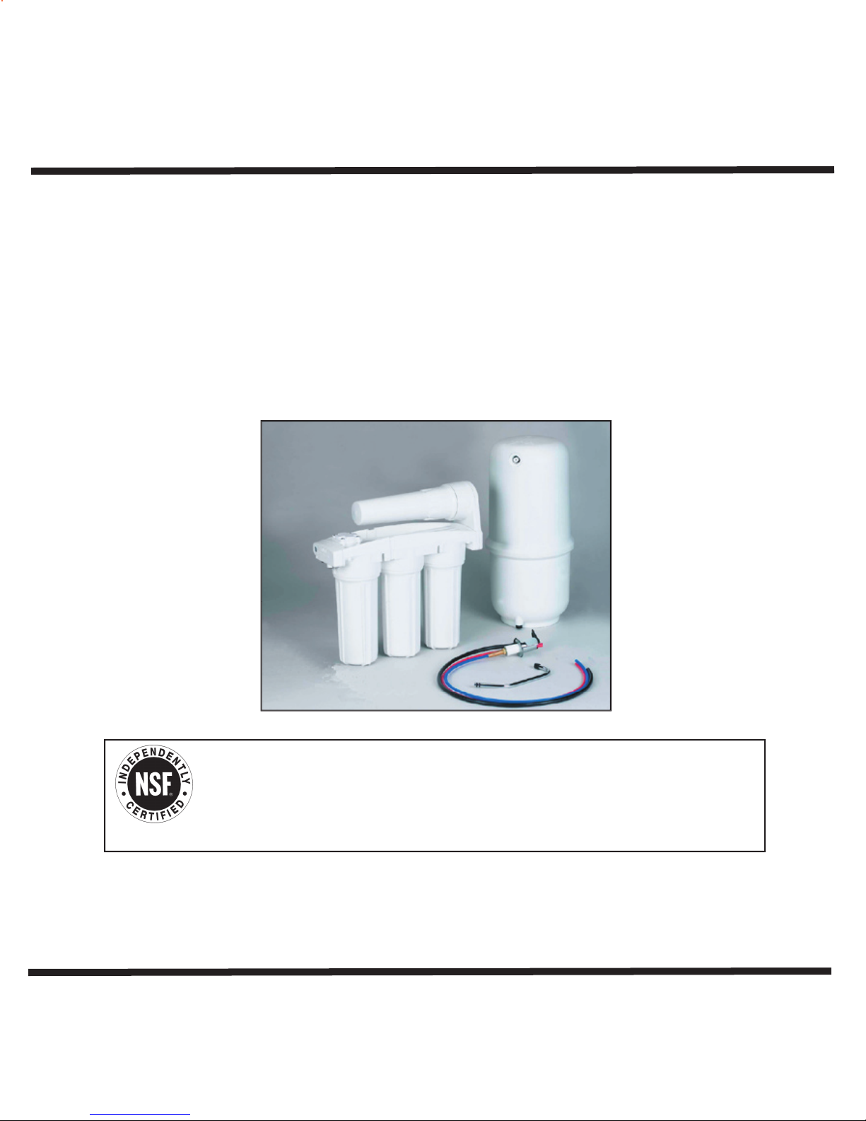
Thank you for your purchase of a state of the art Reverse Osmosis (RO) water treatment system. Water quality concerns
materials that cause bad taste and odor are greatly reduced.
water treatment system is equipped with a storage tank.
The fi nal stage is an inline granular activated carbon (GAC) fi lter. This fi lter is used after the water storage tank,
and is used as a fi nal polishing fi lter.
are quickly becoming more of a focus for the public. Lately you may have heard about contaminants in the drinking water,
such as arsenic, chromium, cryptosporidium or Giardia. There may also be some local water issues in your area such as high
levels of lead and copper. This water treatment system has been designed and tested to provide you with high quality water
for years to come. The following is a brief overview of the system.
Your Reverse Osmosis System:
Osmosis is the process of water passing through a semi permeable membrane in order to balance the concentration of
contaminants on each side of the membrane. A semi permeable membrane is a barrier that will pass some particles like clean
water, but not other particles like arsenic and lead.
Reverse osmosis uses a semi permeable membrane; however, by applying pressure across the membrane, it concentrates
contaminants (like a strainer) on one side of the membrane, producing crystal clear water on the other. This is why RO
systems produce both clean drinking water and waste water that is fl ushed from the system. This reverse osmosis system also
utilizes carbon block fi ltration technology, and can therefore provide a higher quality drinking water than carbon fi ltration
systems can alone.
Your system is a fi ve stage RO which is based upon fi ve separate treatment segments within the one complete water fi ltration
system. These stages are as follows:
Stage 1 – Sediment fi lter, recommended change 6 months.
Stage 2 and 3 – Carbon fi lters, recommended change 6 months.
Stage 4- Membrane, recommended change 2-5 years.
Stage 5- Carbon inline fi lter, recommend change 6 - 12 months.
System Maintenance
Just because you can not taste it, does not mean that it is not there. Contaminants such as lead, chromium and arsenic (to
name a few) are undetectable to the taste. Additionally, over time if you do not replace the fi lter element, other bad tastes
and odors will be apparent in your drinking water.
This is why it is important to change out your fi lter at the recommended intervals as indicated in this system manual. When
replacing the fi lter elements, pay special attention to any cleaning instructions.
Page 3

Tools Recommended For Installation
Adapta Valve Installation
Tank Elbow Installation
Annual Maintenance
Trouble Shooting
Arsenic Fact Sheet
Warranty
Page 4
Recommended hardness should not exceed 10 grains per gallon, or 170 ppm. System
The operating pressure in your home should be tested over a 24 hour period to attain the
then a pressure regulator is required.
TDS (Total Dissolved Solids):
Turbidity:
will operate with hardness over 10 grains but the membrane life will be shortened. (Addition of a water
softener may lengthen the membrane life.)
Note: Reverse Osmosis water should not be run through copper tubing as the purity of the water will
leach copper and cause an objectionable taste in water and may cause pin holes. Be sure to follow
any state or local regulations.
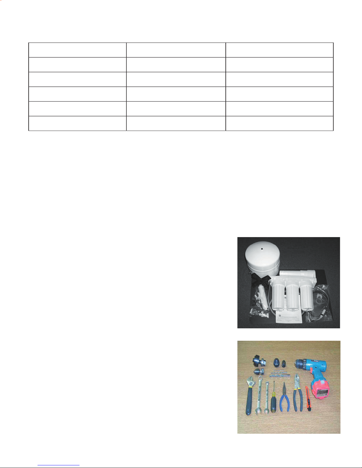
1 Tank – White (Plastic or Metal)
1 Module – White
1 Parts Bag – With a Final Filter
1 Faucet Bag
1 Manual
Tools Recommended For Installation
√ 1 1/4" Hole Saw Bit for Faucet opening
√ Round Knock out Punch for Stainless Sinks, ½” & 1 ¼”
√ Adjustable Wrench
√ Sharp Knife
√ 1 / 2" - 13/16” Open End Wrenches
√ Phillips Screw Driver
√ Needle Nose Pliers – Adjustable Pliers
√ Electric Drill
√ 1/8", 1/4" & 3/8" Drill Bits
Page 5

the faucet to the sink after drilling. Remove all sharp edges.
the desired location. (If drill bit gets hot it may cause the porcelain to
wrench to punch the hole in the sink. Change to the 1 1/4” Hole
The faucet can now be installed.
For the Air Gap Faucet (included), a 1 1/4” hole will be required. If using a non air gap
faucet, a 3/4” hole will be required.
1
/
8
¼
Punch a Hole for the Faucet in a Stainless Steel Sink
If mounting faucet to a Stainless Steel Sink you will need a ½”
& 1 ¼” Hole Punch. The faucet opening should be centered
between the back splash and the edge of the sink, ideally on the
same side as the vertical drain pipe.
¼
Page 6
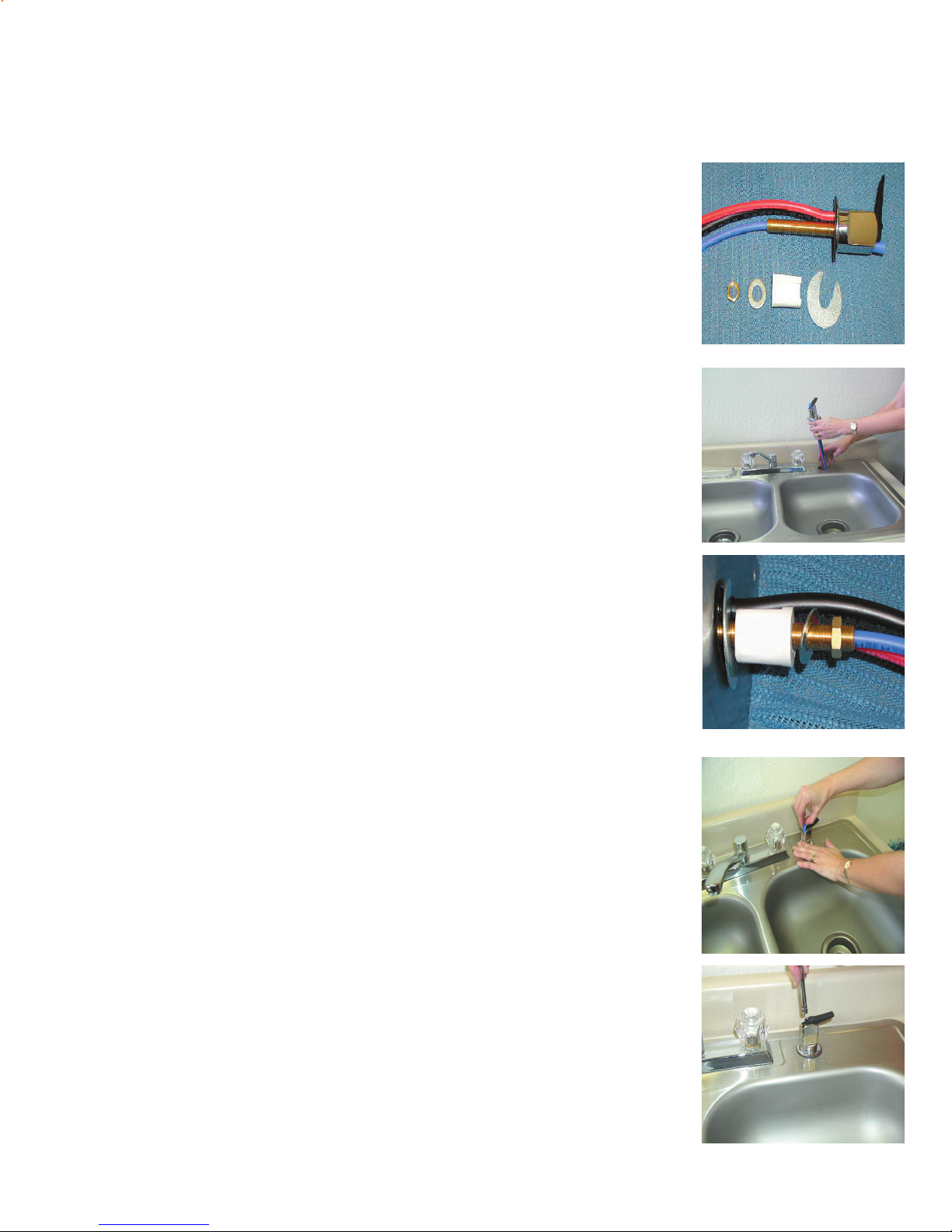
Remove the Brass Nut, Washer, Spacer and Slotted Washer
from Faucet.
1 faucet base with tubing attached
1 small washer
1 brass nut
1 White plastic spacer
1 Slotted washer
Slide tubes through the opening for the
faucet until faucet base is resting on top
of sink.
Slip blue tube through small washer and brass nut. Position
white washer into place then tighten to within ¼” of top.
Slip slotted washer into position. Check orientation of
Faucet on top of sink. Tighten with a wrench.
DO NOT
OVERTIGHTEN. Some porcelain sinks could crack if over
tightened.
The three (3) tubes from the faucet will be cut to length
later in the installation.
Remove the piece of tubing from the top of the
faucet base by pulling upward. Needle nose pliers
can be used to grip the tube.
Insert spout of faucet into the opening in front of the black
lever and push down fi rmly.
Page 7
Adapta Valve Installation
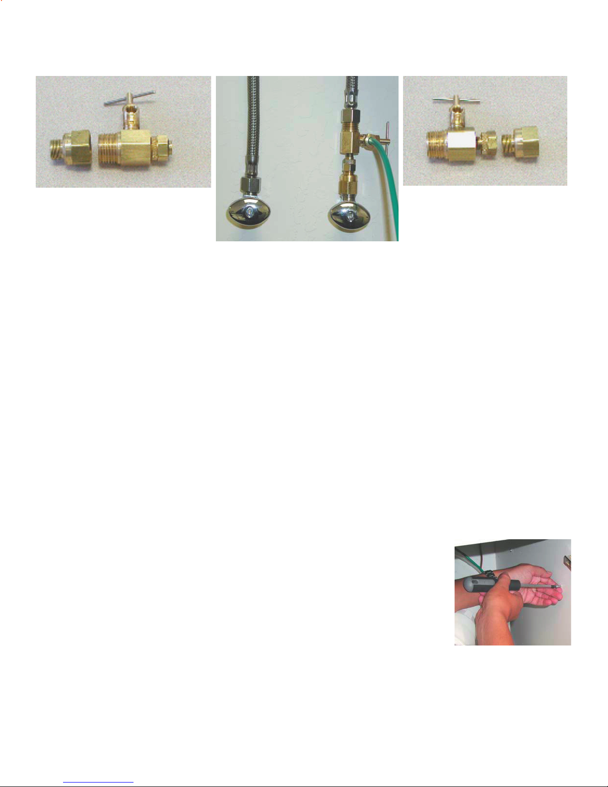
Water supply line to the system must be from the cold water supply line. Hot water
will severely damage the system.
Step 11
Step 12 Attach adapta valve as illustrated in the three photos above, choosing the
Turn off cold water supply to the kitchen faucet by turning the angle stop valve clockwise.
confi guration that fi ts your plumbing. The green tube from inlet side of RO
module will be cut to length and attached later in the installation.
Reverse Osmosis Module Mounting
Determine best location for the RO module to be mounted to allow
for future system maintenance. The parts bag has 2 self tapping
screws. Using a phillips screwdriver, screw them into the cabinet
wall 6 ” apart and at least 16” from the bottom of the cabinet.
Page 8
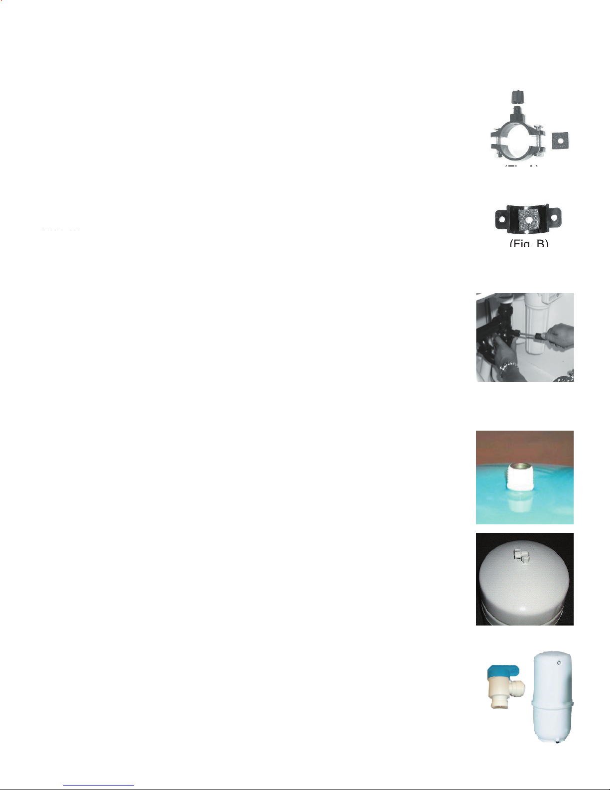
Drain Saddle Installation
(Fig. B)
Thread ball valve directly to plastic tank. This valve does not need tefl on
tape. Tightened until snug and o-ring seals.
Tank
Valve
Drain Saddle fi ts standard 1 ¼” – 1 ½” drain pipes
Gather the pieces of the drain saddle found in parts bag.
The black square foam gasket with a hole cut out of the middle
must be applied to the inside of the drain saddle. Remove sticky
tape backing and stick to the drain saddle matching holes as
shown. Be sure to remove the hole cut out. (Fig. B)
Drill a ¼” hole through the drain pipe at least 1 ½” above the nut of the
P-trap to allow for the removal of the P-trap. Assemble the drain
saddle around the drain pipe. Position the drain saddle over the drilled
hole in pipe. Insert screw driver into the opening of the drain saddle
and align with drilled hole in drain pipe. Using Phillips screw driver
tighten screws evenly and securely on both sides of the drain saddle.
Over tightening the screws may break drain saddle. Caution: Hand
tighten compression nut. If necessary you can turn 1/4 turn with a
wrench. Attach black compression nut, but do not tighten at this time.
The black tubing will be installed later.
1 Black compression nut
1 Semi-circle bracket with fi tting
2 Screws
1 Foam washer
2 Nuts for screws
1 Semi-circle bracket
(Fig. A)
Tank Elbow Installation FRO5-M-MT
Wrap (7 to 12 turns) Tefl on tape clockwise around the male pipe
threads (MPT) on the Stainless Steel fi tting on top of the tank.
Step 18
Thread the plastic elbow (supplied in the parts bag) onto the
stainless steel connection on the top of tank. Tighten using an
adjustable wrench. Do not over tighten as plastic could crack.
Tank Elbow Installation FRO5-M-PT (Plastic Tank)
Do not use Tefl on tape when installing valve to plastic tank.
Page 9
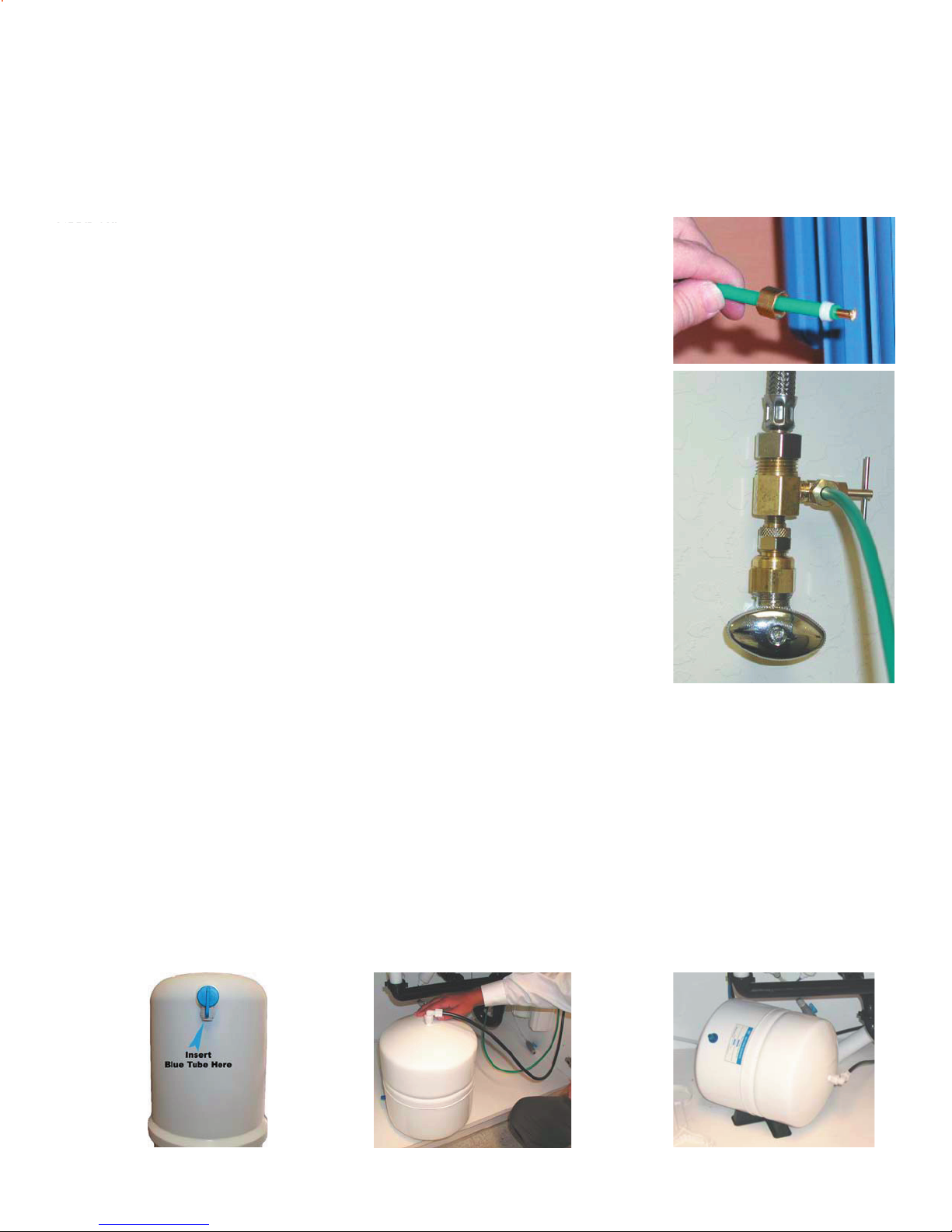
Green Tube Connection
Measure the green tube coming from the port marked TAP on the Reverse Osmosis
Module over to the adapta valve attached to the Angle Stop Valve. Leaving a gentle curve
in the tubing so the tube does not kink. Cut to desired length using a sharp knife.
Remove a brass nut, plastic delrin sleeve and brass insert from
the parts bag. Slide the nut on the tube fi rst, then the Delrin
sleeve (Small taper end of Delrin sleeve must point to the end of
tube). Then insert the brass Insert into the end of the tube.
Insert the green tube into the ¼” opening on adapta valve until
it stops. Slide nut and sleeve down and thread onto the male
pipe threads. Hand tighten brass nut, add one full turn with a
½” wrench for secure fi t.
Connect Blue Tube from TANK port on RO
Module to the Tank
Position tank in desired location. Stand it upright or lay it on its
side (using the black plastic stand FR05-M-MT only). Measure
the blue tube from the RO module port marked TANK over to
the tank and cut it to desired length.
Insert the blue 3/8” tube into the compression nut as far as it
will go. Tighten the compression nut securely with a wrench.
Page 10
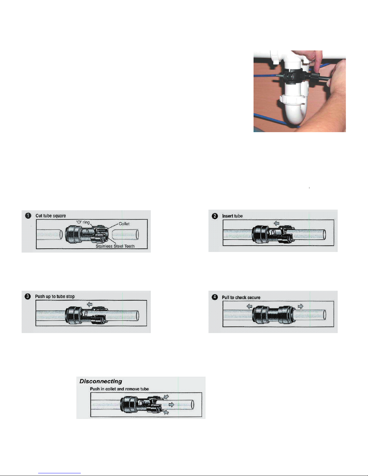
3/8” Black Tube Connection from faucet
This is a gravity fed line, if there is any bend or dip in the
tube the rinse water will not fl ow into the drain properly.
Water will back up and come out the air gap hole in the
The tubing must be as SHORT and STRAIGHT as possible to the drain saddle, making a
To make a connection, the tube is simply pushed into the fi tting. Place a piece of tape 1/2” from end
locking
diameter be free of score marks and that burrs and sharp
the tube stop.
the tube fi rmly in position while the O-ring provides a
tice to test the system prior to leaving site and /or before
To disconnect, ensure the system is depressurized be-
fore removing the tube. Push in collect squarely against
face of fi tting. With the collect held in this position, the
tube can be removed. The fi tting can then be reused.
Remove black plastic nut from drain saddle. Slip black tube
through black nut. Insert black tube into the opening in the
drain saddle and hand tighten the black nut, and add 1/4 turn
with a wrench.
®
Page 11
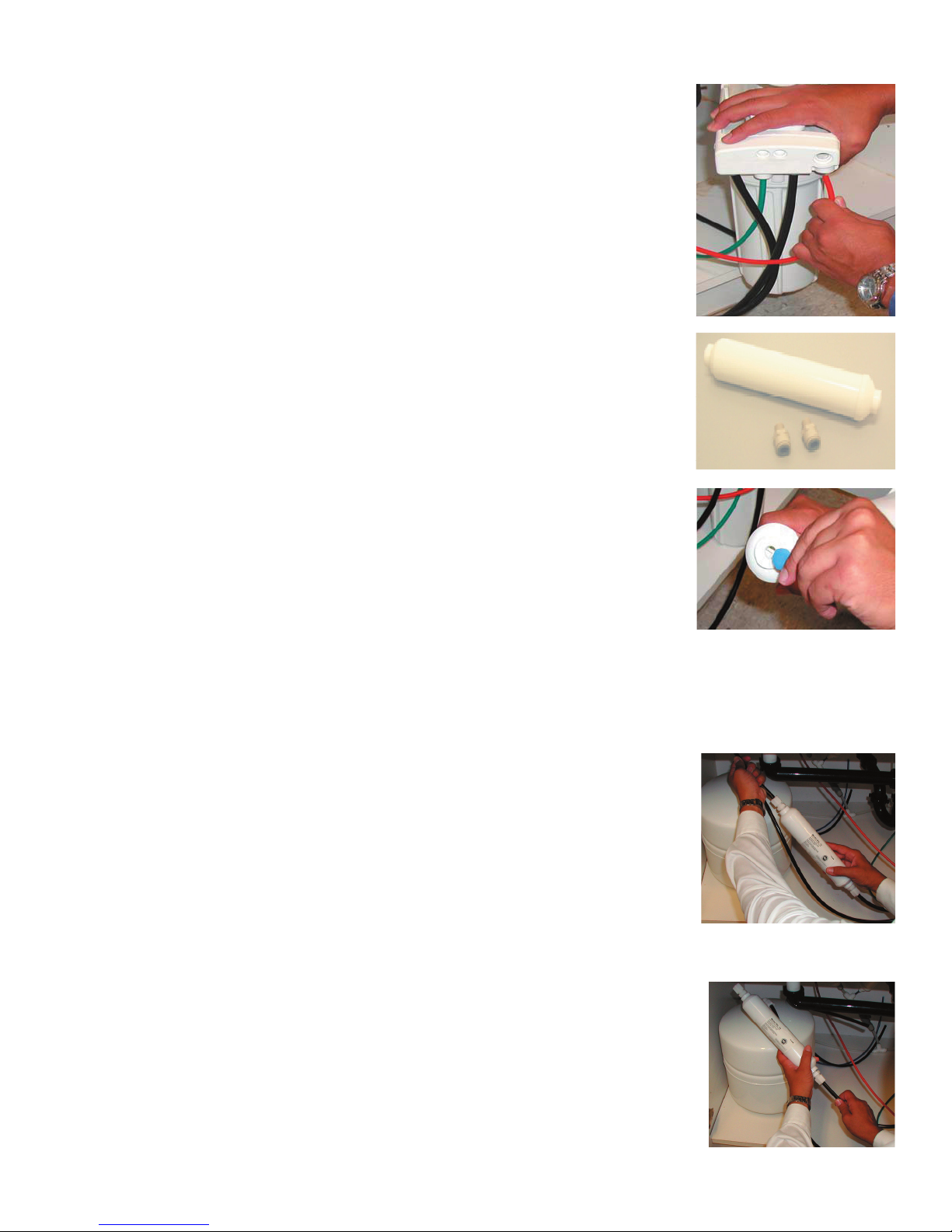
Connect the Red Tube from Faucet to RO Module
Insert the red 1/4” tube from the faucet into the port on the
module marked DRAIN. Make sure the tube is pushed in all
the way to the tube stop.
Final Filter Installation
The Final Filter and 2 plastic connectors are in the parts
bag.
Remove the blue/white caps from the fi nal fi lter.
Thread the 3/8” plastic connector into the inlet side of the fi nal
fi lter and tighten. Thread the 1/4” connector to the outlet side of
fi nal fi lter (refer to directional arrow on fi lter).
Push in 3/8” blue tube from the manifold into the 3/8”connector
on the fi nal fi lter.
Insert the 1/4” blue tube from the faucet into the outlet of the
fi lter. Note: Flow arrow should be pointing toward the faucet.
Page 12

Start up Instructions
After water trickles out of the faucet, close RO faucet so the tank will fi ll with water.
Step 1
Step 2
Step 3
Step 4
Step 5
Turn on the incoming cold water at the angle stop valve. Open the needle valve on the
brass Adapta Valve by turning counter clockwise. Check the system for leaks and tighten
any fi tting as necessary. (Check frequently over the next 24 hours to ensure no leaks are
present).
Open the RO faucet and leave it open until water begins to trickle out, (it will come out
slowly).
The
tank will take approximately 6 hours at fi rst to fi ll completely depending on the size of the
membrane, local water temperature and pressure.
After the Tank has fi lled, open the RO Faucet and drain the Tank completely to remove
carbon particles from the system. Repeat steps 3 and 4, this initial fl ushing of the system
should take about a day to complete. Note: The fl ushing of the system is only necessary
during initial installation.
If system is connected to an Ice Maker, turn the Ice Maker off until fl ushing is complete
and the tank has refi lled. The system should have an in-line valve installed before the Ice
Maker so it can be closed to prevent water fl owing to the Ice Maker. Your tank must be
allowed to fi ll up in order for the unit to shut off. (If you are installing an Ice Maker Kit, tee
off after the fi nal fi lter).
Note:
Your reverse osmosis system contains replaceable treatment components that are critical
for effective contaminant reduction. Periodic inspection and following proper system
maintenance is critical for continued performance.
Page 13
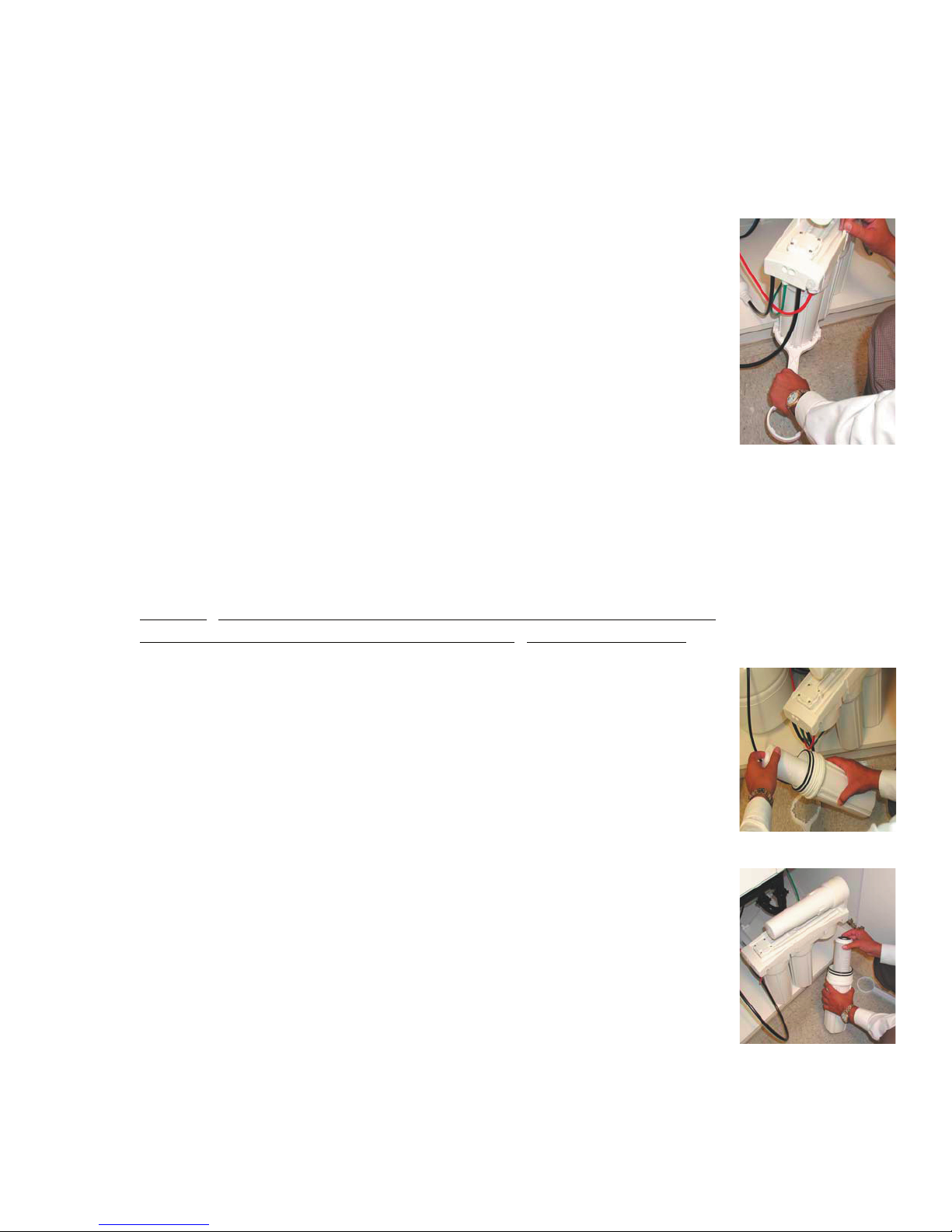
√ One 10” sediment fi lter (part no. 104017) √ Bucket to catch water from fi lter housings.
Turn water on to the unit by turning the needle valve on the adapta
valve counter clock wise.
√ Two 10” carbon fi lters (part no. 101009)
Turn off incoming water supply to the RO by turning the needle valve
on the adapta valve clockwise. (The green tube is connected to the
adapta valve.)
Open RO Faucet to allow water to drain from the tank until completely
empty. Water can be saved in a container for drinking or to rinse
system parts.
Let system sit for 10 – 15 minutes after tank is empty to depressurize
before attempting to remove fi lter housings.
For more leverage, leave RO module attached to wall of cabinet. If
you are unable to access the module you may remove it to change
fi lters. Starting with the closest housing, remove and empty water, then
nd
discard fi lters. Continue on to the 2
and/or 3rd Bowls.
Clean all fi lter housings (bowls) with a mild soap solution and rinse
with water. Check O-rings and lubricate with water soluble lubricant.
KY Jelly® , Canola oil and other water based lubricants can be used,
petroleum based lubricants (such as Vaseline
®) must not be used.
The sediment fi lter has a cloth like appearance. It should be in the 1
housing on the side with tubing connections.
Insert the Carbon Block fi lter (fi lter has a gasket on each end) into
the middle housing.
Repeat this step for 3rd housing .
st
Page 14
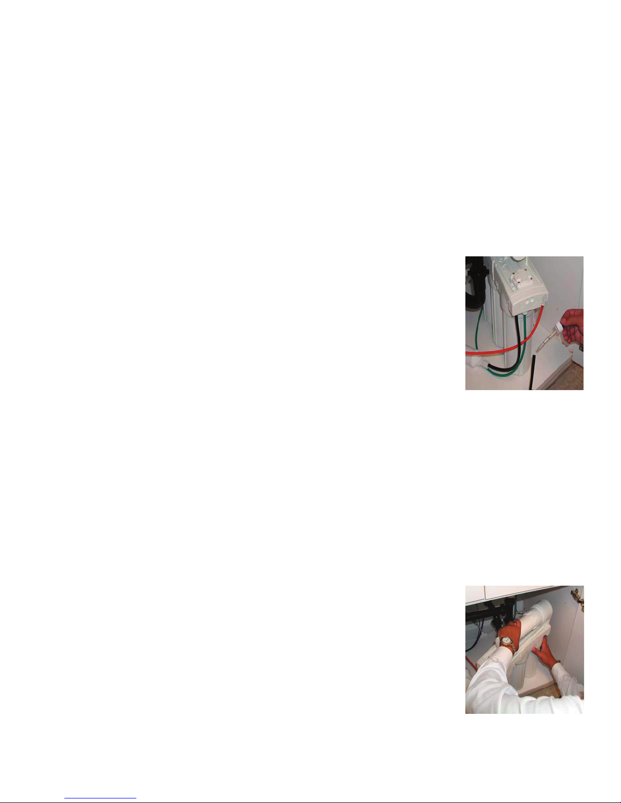
Annual Maintenance
vessel counter clockwise to loosen.
Turn off the cold water supply and open the RO faucet to drain the
tank.
Be sure water is turned off before going to step 2.
Perform 6 month system maintenance. (previous section)
The Final Filter (should be replaced annually. Remove white nuts at both ends of the fi lter
to replace the old fi nal fi lter. Replace with new fi lter and connectors (as shown on page 10).
The white nuts can be re-used so they do not have to be removed from the tubes.
Note: Flow arrow on fi nal fi lter must be pointing in the direction of the
faucet.
Annual sanitizing of unit is recommended to prevent bacteria
growth. Remove the Blue Tube from the module marked TANK.
Using a clean eye dropper insert ½ teaspoon of 3% hydrogen
peroxide or common household bleach into the blue tube. This will
fl ow into the tank once water is turned back on to unit. Reattach the
blue tube to the port marked TANK on the module. Then follow steps
3 and 4 on page 12 in the start up procedure .
Membrane Maintenance
Membranes have a life expectancy of between 2 and 5 years, depending on the incoming water
conditions and the amount of use of the RO system.
Normally, a membrane would be replaced during a semiannual or annual fi lter change. However, if
at any time you notice a reduction in water production or an unpleasant taste in the reverse osmosis
water, it could be time to replace the membrane.
Page 15
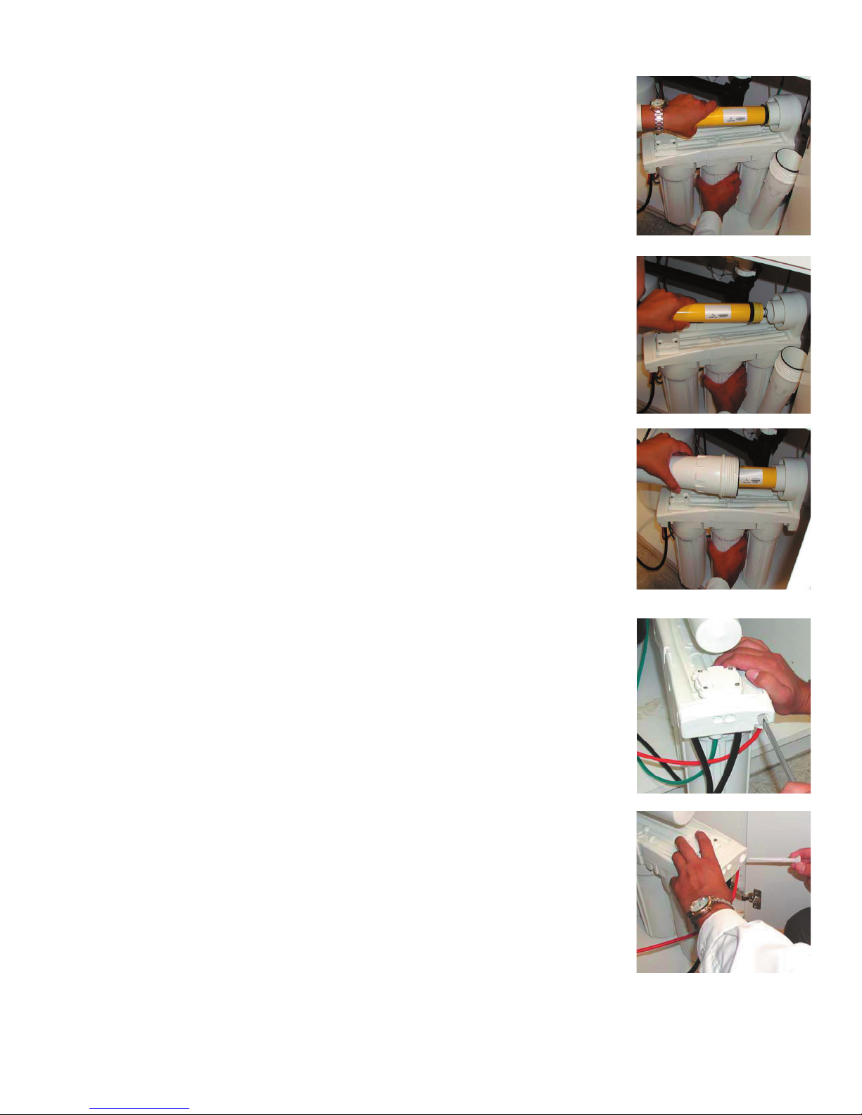
Pull fi rmly on the membrane to remove from the housing and
discard.
Unwrap new membrane and lubricate the o-rings with water
soluble lubrication such as KY Jelly ® before inserting into
housing. Insert end with the two black O-rings into the cap.
Twist the membrane as you push fi rmly into the cap.
Replace the vessel onto the cap by turning clockwise. Tighten
securely.
The fl ow restrictor plug (part no. 164015) must be replaced each
time you change the Membrane (part no.110015.) Remove the
existing fl ow restrictor with a screwdriver and discard.
Insert the new fl ow restrictor plug and tighten.
Follow the Start Up Instructions on page 11.
Page 16
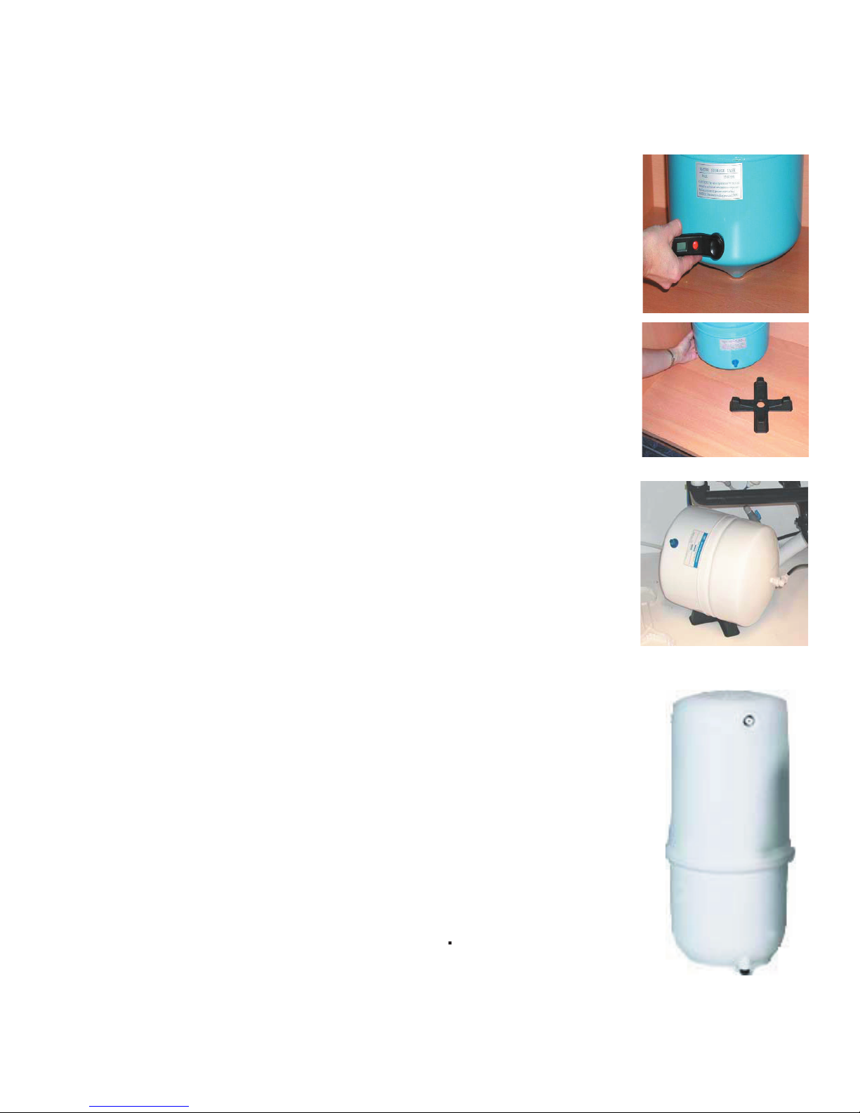
Checking Air Pressure in the Tank
Valve is located at the base of the tank. You will need to unscrew the
Note:
Check air pressure when tank is empty.
Use a digital air gauge to check the air pressure in the tank. You
should always have between 5 -7 psi on an empty tank. If you have
more than 7 psi release air and recheck. If you have less than 5 psi,
add air. Air can be added with a bicycle pump.
Your unit comes with a stand for your storage tank (model FRO5M-MT only)to sit on if you need to turn the unit on its side. This
allows air fl ow under the tank keeping moisture and standing water
from rusting out the bottom of your tank which voids your warranty.
Use a digital air gauge to check the air pressure in the tank. You
should always have between 5 -7 psi on an empty tank. If you have
more than 7 psi release air and recheck. If you have less than 5 psi,
add air. Air can be added with a bicycle pump.
Page 17

TROUBLE SHOOTING
Premier sells a booster pump if home water pressure is
low. Maker sure water supply is turned on and Adapta
Valve is all the way open
Crimps in tubing Check tubing and straighten or replace as necessary.
Clogged pre-fi lters Replace pre-fi lters.
Fouled membrane Replace membrane and clean fl ow restrictor.
up of the RO system. This milky look will disappear
during normal use within 1-2 weeks. If condition reoccurs
after fi lter change, drain tank 1 to 2 times.
High water pressure Check incoming water pressure to make sure it does not
exceed 100 psi. A presser relief valve may be necessary.
High air pressure in tank Empty storage tank of water. Set tank air pressure to 5
psi. See previous page.
4. Noise from faucet or drain Air gap faucet Inherent sound with air-gap faucets.
Location of drain saddle See diagram for proper location of drain saddle.
Higher capacity membrane Normal with high capacity membrane
High water pressure Check incoming water pressure to make sure it does not
exceed 100 psi. A presser relief valve may be necessary.
the air gap feature Drain tube clogged/restricted Caused from dishwasher or garbage disposal.
Disconnect the 3/8” black tube at the drain, clean the 3/8”
black tube out with a wire, then reconnect.
production rate.
Low water pressure See #1 Above
Too much air in tank Add air if below 5 psi and bleed if above 5 psi. Check
only when tank is empty of water. See previous page.
fi lter housing Missing or kinked O-ring Turn off the water supply. Release the pressure, remove
bowl and replace the O-ring. (p/n 113043). Make sure
the O-ring is seated in the fi lter bowl properly before
reinstalling the fi lter bowl.
Page 18

Performance Data Sheet
Flowmatic Systems Inc.
11611 SW 147 Court
Dunnellon, FL 34432 USA
FMRO5-M-PT, FMRO5-M-MT
System conforms to NSF Standard 58 for specifi c claims.
GENERAL USE CONDITIONS:
1. System to be used with municipal or well water sources treated and tested on regular basis to insure bacteriological safe quality. Do not use
with water that is microbiologically unsafe or unknown quality without adequate disinfection before and after the system. Systems certifi ed for cyst
reduction may be used on disinfected water that may contain fi lterable cysts.
2. This system is acceptable for treatment of infl uent concentrations of no more than 27 mg/L nitrate and 3 mg/L nitrite in combination measured as
N and is certifi ed for nitrate/nitrite reduction only for water supplies with a pressure of 280 kPa (40 psig) or greater. If your water supply is under 40
psi, Flowmatic recommends the use of a RO booster pump for proper operation.
3. Operating Temperature: Maximum: 100°F (40.5°C) Minimum: 40° (4.4°)
4. Operating Water Pressure: Maximum: 85 psi (5.95kg/cm2) Minimum: 40 psi (2.8kg/cm2)
5. pH 3 to 11
6. Hardness of more than 10 grains per gallon (170 ppm) may reduce TFM membrane life expectancy.
7. Recommend TDS (Total Dissolved Solids) not to exceed 1800 ppm.
RECOMMENDED REPLACEMENT PARTS AND CHANGE INTERVALS:
Depending on incoming feed water conditions replacement time frame may vary.
Change Time Description
6 months: Sediment Pre-fi lter; Carbon Pre-fi lters
12 months Final Carbon fi lter
2 to 5 years R.O. Membrane
This system has been tested according to NSF/ANSI 58 for reduction of the substances below. The concentration of the indicated substances in water entering the
system was reduced to a concentration less than or equal to the permissible limit for water leaving the system as specifi ed in NSF/ANSI 58. This system has been
tested for the treatment of water containing pentavalent arsenic (also known as As (V), As (+5), or arsenate) at concentrations of 0.30 mg/L or less. This system
reduces pentavalent arsenic, but may not remove other forms of arsenic. This system is to be used on water supplies containing a detectable free chlorine residual
at the system inlet or on water supplies that have been demonstrated to contain only pentavalent arsenic. Treatment with chloramine (combined chlorine) is not
suffi cient to ensure complete conversion of trivalent arsenic to pentavalent arsenic, Please see the Arsenic Facts section of the Performance Data Sheet for further
information.
Avg. In. Avg. Eff. % Reduction pH Pressure Max Eff. Inf. challenge Max Allowable
(mg/L) (mg/L) mg/L concentration concentration
mg/L mg/L
Arsenic (Pentavalent) 334.62 ug/L 5.039 ug/L 98.4% 50psi 19 ug/L 0.30±10% 0.010 mg/L
Barium Reduction 10.2 0.13 98.7% 7.24 50psi 0.27 10.0±10% 2.0
Cadmium Reduction 0.031 0.0001 99.7% 7.49 50psi 0.0009 0.03±10% 0005
Chromium (Hexavalent) 0.30 0.006 98.0% 7.24 50psi 0.013 0.03±10% 0.1
Chromium (Trivalent) 0.30 0.003 99.0% 7.24 50psi 0.008 0.03±10% 0.1
Copper Reduction 3.0 0.04 98.7% 7.64 50psi 0.06 3.0±10% 1.3
Cysts 222,077#/ml 10 #/ml 99.99% 50psi 58 minimum 50,000/mL N/A
Fluoride Reduction 8.0 0.33 95.9% 7.49 50psi 0.47 8.0±10% 1.5
Lead Reduction 0.15 0.004 97.3% 7.49 50psi 0.008 0.15±10% 0.0107
Nitrite and Nitrate 29.2 6.6 77.3% 7.64 50psi 10.0 3.0±10% 10.0
Nitrate Reduction 26.3 6.1 76.8% 7.64 50psi 10.0 3.0±10% 10.0
Nitrite Reduction 2.8 0.5 82.1% 7.64 50psi 0.77 3.0±10% 1.0
Perchlorate 0.10 0.003 96.5% 7.39 50 psi 0.005 mg/L 0.10±10% 0.006
Radium 226/228 25pCi/L 5pCi/L 80.0% 7.24 50psi 5pCi/L 25pCiL±10% 5pCiL
Selenium 0.10 <0.001 99.0% 50psi <0.001 0.10±10% 0.05
TDS 764 36 95.2% 7.84 50psi 50.0 750±40mg/L 187
Turbidity 81 NTU 0.15 NTU 99.8% 50psi 0.28 NTU 11±1 NTU 0.5 NTU
Recovery - 16.34% Daily Production Rate - 17.32 GPD Effi ciency - 8.91%
Effi ciency rating means the percentage of the infl uent water to the system that is available to the user as reverse osmosis treated water under operating
conditions that approximate typical daily usage.
There is an average of 4 gallons of reject water for every 1 gallon of product water produced. Testing performed under standard laboratory conditions,
actual performance may vary. Refer to owners manual for further maintenance requirements and warranty information.
Phone: (352) 465-2000 Fax: (352) 465-4898
Page 19

Arsenic Fact Sheet
Arsenic (As) is a naturally occurring contaminant found in many ground waters. Arsenic
in water has no color, taste or odor. It must be measured by an arsenic test kit or lab test.
Public water utilities must have their water tested for arsenic. You can obtain the results
from your water utility contained with in your consumer confi dence report. If you have your
own well, you will need to have the water evaluated. The local health department or the
state environmental health agency can provide a list of test kits or certifi ed labs.
There are two forms of arsenic: pentavalent arsenic (also called As (V), As (+5))and trivalent
arsenic (also called As (III), As (+3)). In well water, arsenic may be pentavalent, trivalent,
or a combination of both. Although both forms of arsenic are potentially hazardous to your
health, trivalent arsenic is considered more harmful than pentavalent arsenic.
RO systems are very effective at removing pentavalent arsenic. A free chlorine residual
will rapidly convert trivalent arsenic to pentavalent arsenic. Other water treatment
chemicals such as ozone and potassium permanganate will also change trivalent arsenic
to pentavalent arsenic. A combined chlorine residual (also called chloramine) may not
convert all the trivalent arsenic. If you get your water from a public water utility, contact
the utility to fi nd out if free chlorine or combined chlorine is used in the water system.
This reverse osmosis system is designed to remove up to 98% of pentavalent arsenic. It
will not convert trivalent arsenic to pentavalent arsenic. Under laboratory standard testing
conditions, this system reduced 0.30 mg/L (ppm) pentavalent arsenic to under 0.010 mg/L
(ppm) (the USEPA standard for drinking water). Actual performance of the system may
vary depending on specifi c water quality conditions at the consumer’s installation.
The RO component of this reverse osmosis system must be maintained according to its
recommended maintenance cycle.
California Proposition 65 Warning
WARNING: this product contains chemicals know to the State of California to cause cancer
and birth defects or other reproductive harm. (Installer: California law requires that this
warning be given to the consumer).
Page 20
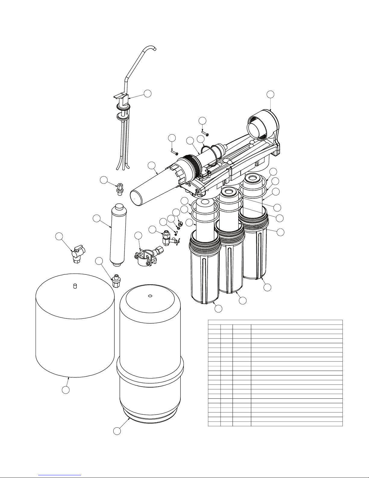
1 1 100017
GAC-IL-10-1-4 F
2 2 101009 CARBON BLOCK-10 INCH-5M-CTG-WATTS
3 1 104017 SED-SPUN-10 INCH-5M-CTG
4 1 110015
MEM-TFM-50 GPD-MANIFOLD
5
3 113018 BOWL-MANIFOLD
6 1 113035
Membrane Vessel - Manifold
7 6 113041 O-RING-BOWL-MANIFOLD-341
8 1 113045 O-RING-VESSEL-MANIFOLD-233
9 1 116063 Faucet-AG-CHR-3-8-With ADPT
10 1 119007 TANK-PRESS-3 GAL WHITE
11 1 119009
Tank-Pres-Plastic-3 Gal-White
12 1 125017 CON-PL-1-4CX1-4M
13 1 131002 NUT-BR-1-4 C INCH
14 1 131012 SLEEVE-DELRIN-1-4 INCH
15 1 131017
INSERT-BR-1-4 INCH
16 1 134007 VALVE-ADAPTA PREMIER
17 1 134023 VALVE-BALL-PLAS-ELB-1-4FX3-8JG
18 2 146004
SCREW-#10-1 INCH PHIL PANHEAD
19 1 164016 Drain Saddle 3-8
20 1 400031
CON-3-8CX1-4M CELCON
21 1 610023 Prepared Lid Manifold Section
Parts List
ITEM QTY PART NU DESCRIPTION
9
18
18
12
6
4
8
21
7
7
7
7
2
2
5
5
5
3
7
7
13
14
15
16
19
1
20
17
10
11
Page 21
Serial No. _____________________
TFM
Page 22

Limited Warranty
Flowmatic warrants each reverse osmosis system to be free from defects in material and
workmanship under normal usage for a period of one year from date of original shipment.
In the event of such defects within the warranty period, Flowmatic will, at its option, replace
or recondition the product without charge. This warranty does not cover system installation
(which is not performed by the manufacturer) or return freight to the factory for inspection.
This shall constitute the sole and exclusive remedy for breach of warranty, and Flowmatic shall
not be responsible for any incidental, special or consequential damages, including without
limitation, lost profi ts or the cost of repairing or replacing other property which is damaged if
this product does not work properly, other costs resulting from labor charges, delays, vandalism, negligence, fouling caused by foreign material, damage from adverse water conditions,
chemical, or any other circumstances over which Flowmatic has no control.
This warranty shall be invalidated by any abuse, misuse, misapplication or
improper installation of the product. THIS WARRANTY IS IN LIEU OF ALL OTHER
WARRANTIES, EXPRESS OR IMPLIED, INCLUDING ANY IMPLIED WARRANTIES
OF MERCHANTABILITY OR FITNESS FOR A PARTICULAR PURPOSE. Any implied
warranties that are imposed by law are limited in duration to one year. In order for this
limited warranty to be valid, reverse osmosis systems must be installed and maintained
according to the manufacturer’s written instructions and procedures. Warranty is void in the
event product identifi cation label is removed from the system.
Some states do not allow limitations on how long an implied warranty lasts, and some
states do not allow the exclusion or limitation of incidental or consequential damages.
Therefore the above limitations may not apply to you. This Limited Warranty gives you
specifi c legal rights, and you may have other rights that vary from state to state. You should
consult applicable state laws to determine your rights.
 Loading...