

Page 1
Installation Instructions
SYSTEM #817518
2010 FORD MUSTANG V6
409S® Stainless Steel
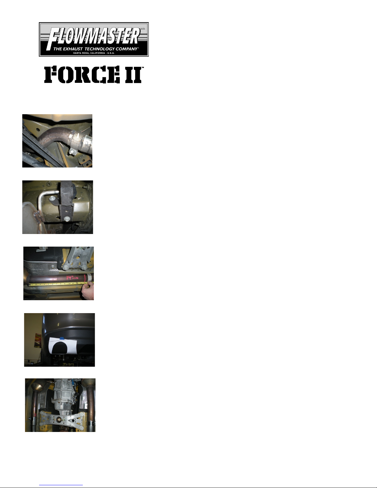
1) Loosen the 15mm nut on the clamped connection between the muffler and
over-axle pipe and also the over-axle pipe to the factory Y-pipe.
2) Unbolt the mounting brackets that m ount the muffler to the frame (these are
the two that connect the hangers on the muffler body to the frame). The mount
connecting the hanger welded to the inlet pipe should remain bolted to the frame.
Once these two hangers are unbolted, lower the muffler from the vehicle. Do not
discard the OEM mounting brackets or hardware as they will be used in the
installation of the new system. Lower the factory over-axle pipe from the vehicle and
set aside.
3) To install the new Flowmaster Scavenger X-pipe assembly #16676S, the
factory Y-pipe must be removed. To do this, measure back 14.00” from the weld at
the rear of each of the catalytic converters and make a mark on both pipes. Be sure
to double check that the measurements are correct and cut both pipes on the marks.
Remove any burrs.
4) Because there is no cutout in the rear valance for the left side tailpipe, it will
be necessary to make a new cutout. Follow the instructions on the attached
template to properly align and make the cutout.
5)
#16676S. Place the assembly up into position and fully slide onto the back of the
factory front pipes, support the rear of the assembly with a stand. Tighten the
clamps enough to hold, but still allow for adjustment. Flowmaster embossing should
be facing the ground.
Place a 2¼” clamp onto the inlets of the new Scavenger X-pipe assembly
Page 2
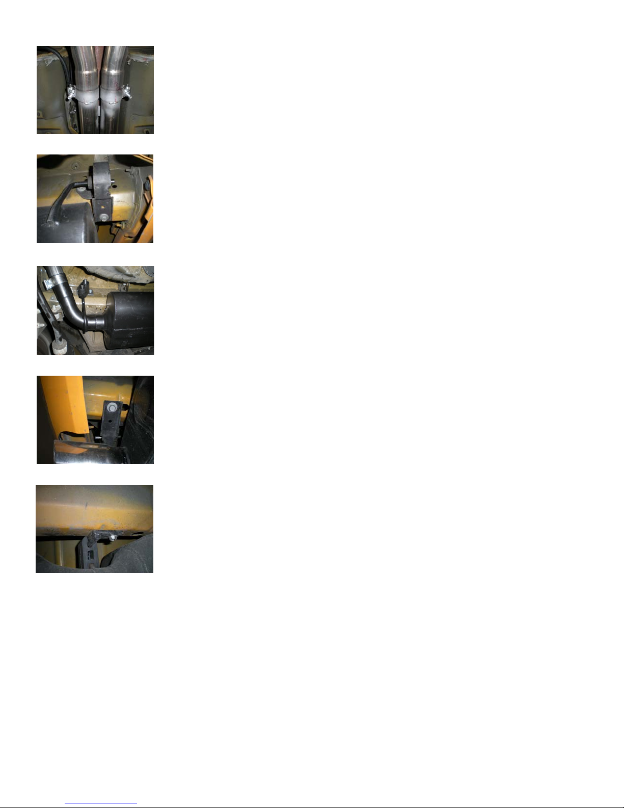
6) Place a 2¼” clamp onto the slip-fit of over-axle pipe #16679S and slide onto
the back of the right Scavenger outlet and support with a stand. Repeat this step with
the left over-axle pipe #16680S.
7) Install the OEM hanger bracket removed from the rear of the factory muffler
onto the rear hanger of m uffler #852467-231. Place the muffler up into position and
connect the muffler inlet to the over-axle pipe. Bolt the hanger bracket to the frame
using the OEM hardware from Step 2.
8) Place the HA168 rubber hanger onto the hanger welded to t he front of muffler
#852467-231. Connect hanger assembly #428HA to t he rubber mount and s ecure to
the existing holes in the frame using the supplied 5/16” x 1” thread cutting bolts.
9) Install the OEM hanger bracket removed from the front of the factory muffler
onto the rear hanger of muffler #852467-232. Place the muffler up into position and
connect the muffler inlet to the over-axle pipe. Bolt the hang er bracket to the frame
using the OEM hardware.
10) Place the HA168 rubber hanger onto the hang er welded to the f ront of m uffler
#852467-232. Connect hanger assembly #415HA to the rubber mount and secure to
the existing hole in the frame using the supplied 5/16” x 1” thread cutting bolt.
11) Adjust the position of all pipes and mufflers to provide a satisfactory fit. This is a tight fitting s yst em , so
take your time and be patient, tightening and adjusting a little bit at a time. Be sure to maintain an adequate
clearance around all parts of the system to avoid rattles or damage to heat sensitive components. Once you’re
happy with the fit, tighten all connections down securely. For a cleaner appearance and more secure
installation, we highly recommend welding all slip-fit connections.
Page 3

PACKING LIST
Qty Description
1 Left Muffler Assembly 852467-232
1 Right Muffler Assemb ly 852467-231
1 Scavenger Assembly 16676S
1 Left Intermediate Pipe 16680S
1 Right Intermediate Pipe 16679S
1 Parts Kit PK597
1 Left Muffler Frame Hanger 415HA
1 Right Muffler Fram e H anger 428HA
6 2¼” Band Clamp MC225BS
2 3/8” Hanger Keepers HW501
2 7/16” Hanger Keepers HW502
3 5/16” x 1” Bolt HW229
2 Rubber Hanger HA168
Part#
Page 4
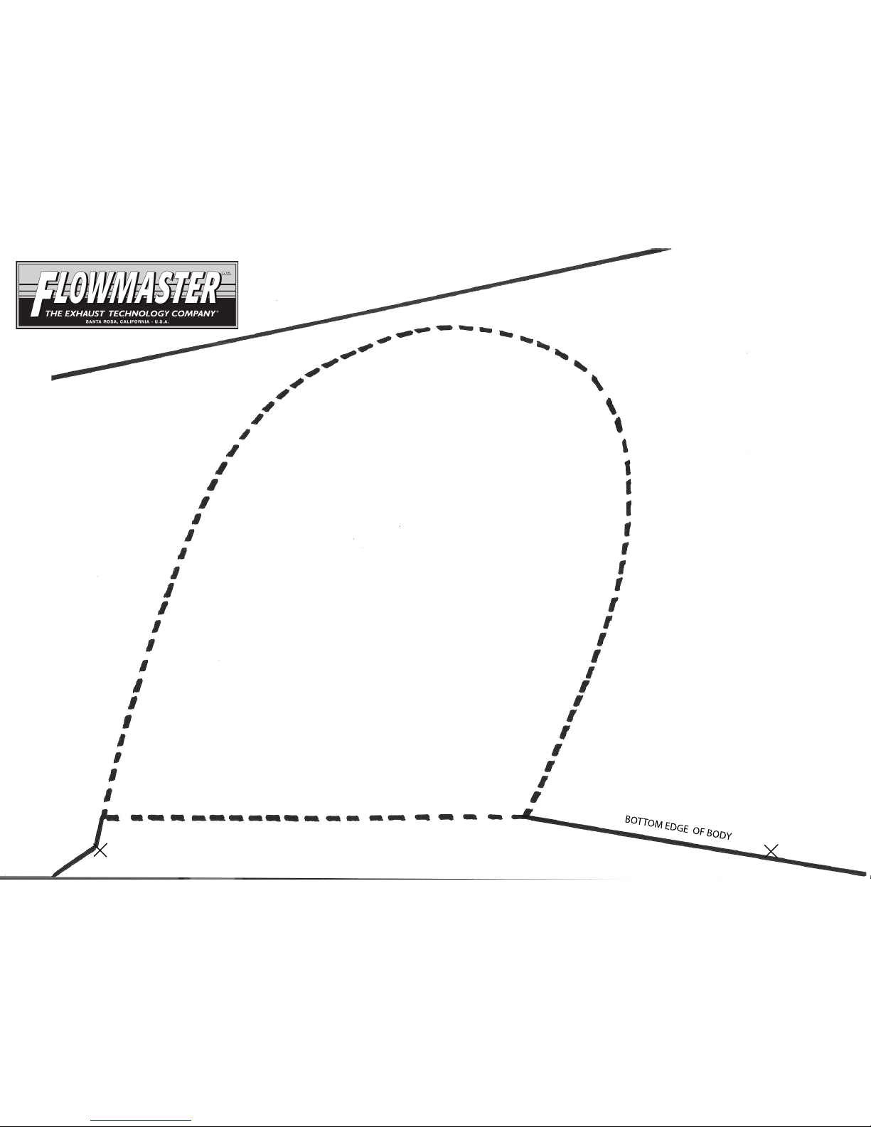
1) Use scissors to cut out this template along the lines.
2) Align the template on the bumper by matching up the
contours of upper body line and the bottom edge of the
bumper valance. Tape the template in place.
3) Use a paint pen or silver marker to mark the contour
onto the valence. Remove template after marking.
4) Use a jigsaw, sawsall or die grinder to carefully cut
along the contour. Use a file to clean up the edges
after cutting.
#817518 - MUSTANG V6
BUMPER CUT-OUT TEMPLATE
INTERNAL REF 9.00”
ALIGN WITH BODY LINE
ALIGN WITH BODY LINE
Page 5
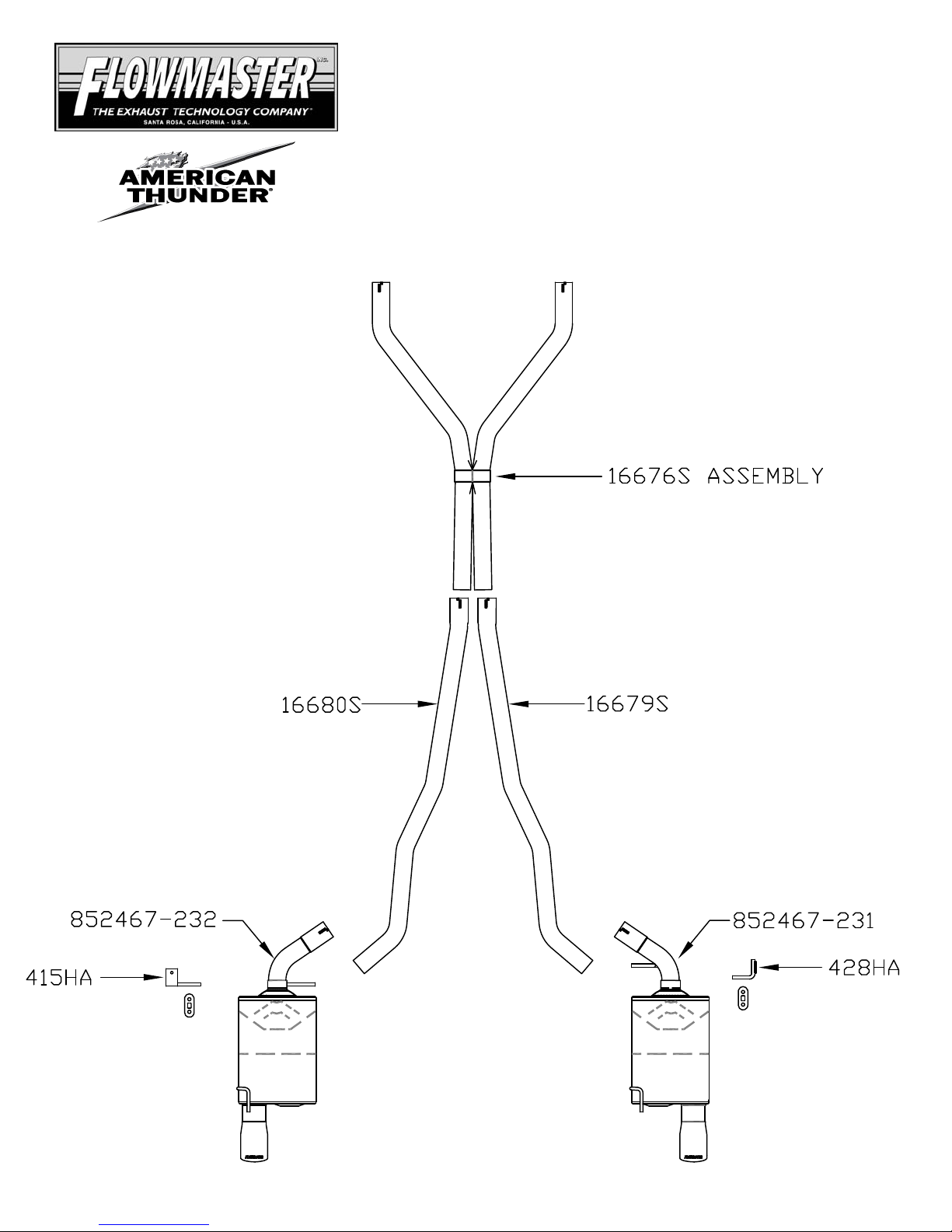
409S® Stainless Steel
Installation diagram for:
SYSTEM #817518
2010 MUSTANG V6
FLOWMASTER PERFORMANCE EXHAUST
EXHAUST SYSTEMS
 Loading...