

Page 1
Installation Instructions for:
SYSTEM #817654
1967-1972 GM C10 PICKUPS
2 ½” HEADER BACK SYSTEM
409S® Stainless Steel
Removal:
1) Raise the rear of the vehicle and support securely with jack stands.
2) Remove the existing system from the header collector or manifold down pipes back.
Installation:
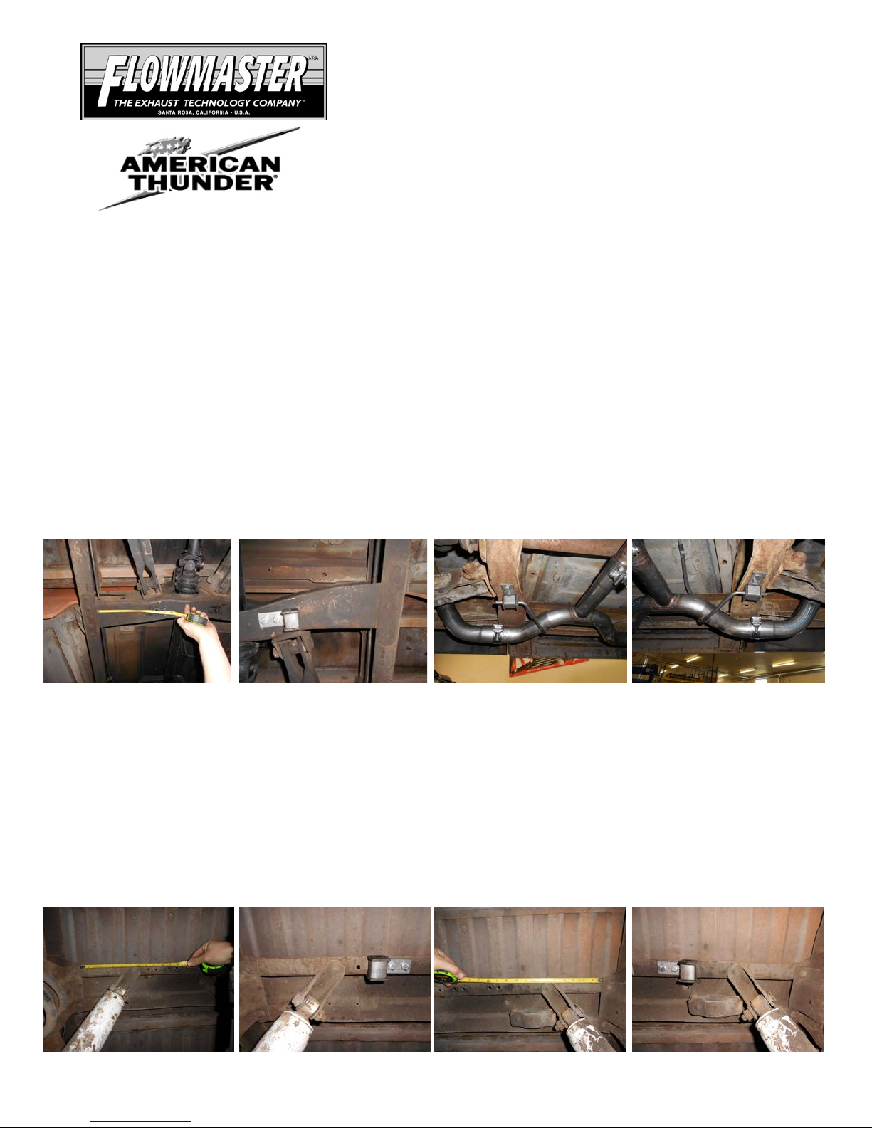
1) Locate the center carrier bearing cross member; this is where the front hangers will be mounted.
Measuring in 9-5/8” from the frame toward the center of the cross member there should be a factory hole.
Using a drill and bit, open the hole up to 3/8”. Then measure in 1.00” toward the center of the vehicle and make
a mark. This is where you will drill a second 3/8” hole. Mount one of the HA572 rubber hangers to the bottom of
the cross member using the 3/8” hardware provided, do this for both sides of t he cross member. See photos
below.
2) Take the right and left H-pipe assemblies, 86074S & 86075S and connect them together at the center
cross-over connection. Place them up into position and connect the hangers on the pipe t o the rubber mounts
installed above. The hanger rods should stick through the rubber block on the HA572 hanger approximately
1.00”. Support the front of the assembly with a stand. Place the provided 2” clamp at the center H-pipe
connection.
3) Locate the rear spring mount cross member, measure in 11 & 12 inches from the edge of the spring
mount and make a mark. This will be on the forward channel of the cross member. Once you have verified the
measurements are correct, center punch the two holes and drill a 3/8” hole in these locations. Mount one of the
HA572 rubber hang ers to the bottom of the cross member using the 3/8” hardware provided. Do this step on
both sides of the cross member. See photos below.
Page 2
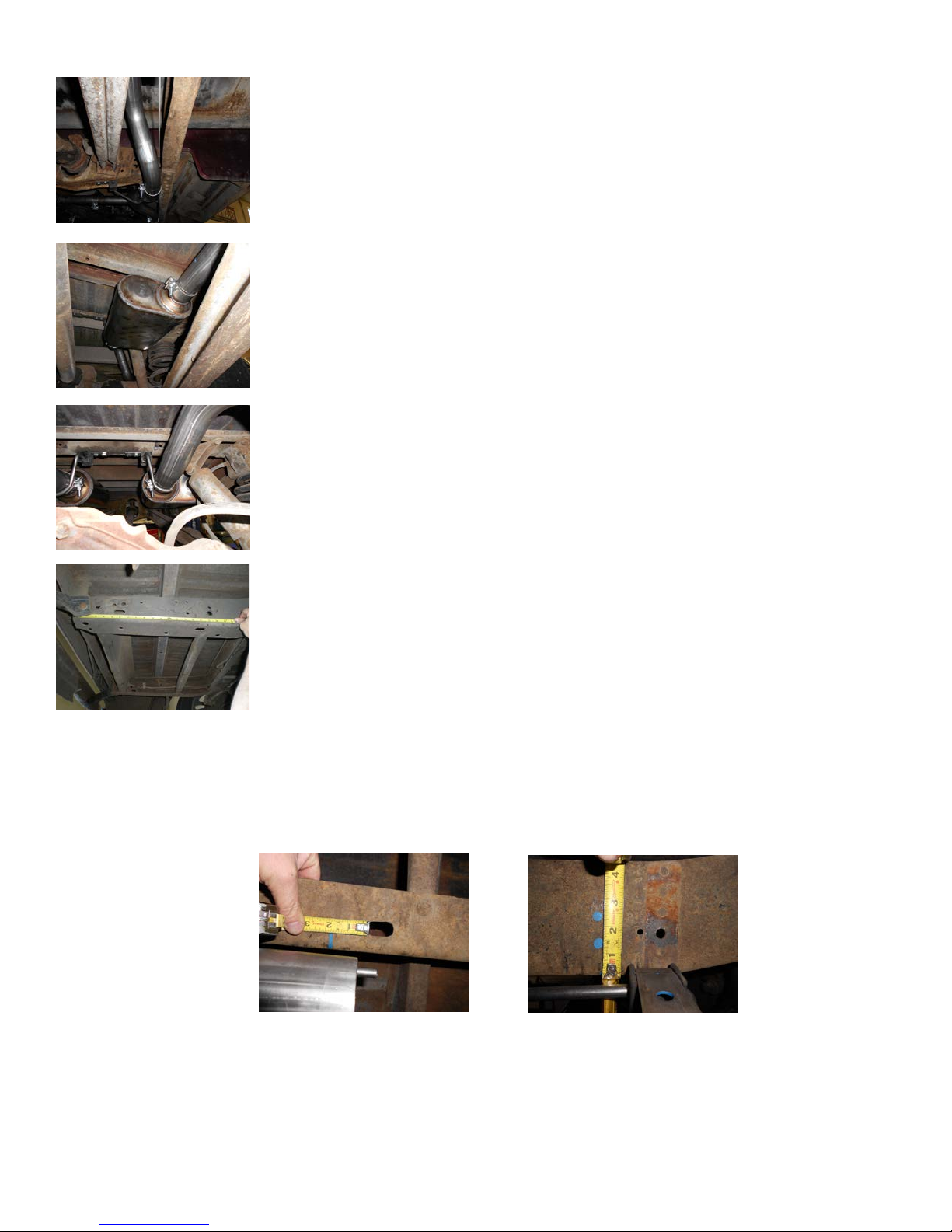
4) Take the 86076S muffler inlet pipes and place a supplied 2½” clamp onto
the expanded end, place them onto the back of the H-pipe assembly’s 86074S &
86075S. Rotate them up into their approximate position and tighten the clamps
enough to hold, but sti l l allow for adju stment.
5) Take one of the 842548-Z mufflers and place a supplied clamp onto the
inlet, slide the inlet onto the back of one of the 86076S inlet pipes with the outlet of
the muffler in the center of the vehicle. Support the muffler with a stand and tighten
the clamp enough to hold , but still allow for adjustm ent .
6) Place a supplied clamp onto the right muffler outlet; take the right over-axle
tailpipe #86077S and slide into the muffler outlet while connecting the front hanger
on the pipe to the rubber mount installed in step 3 above. The tailpipes have been
left long to work for long bed model trucks, for short bed trucks the rear of the
tailpipes will need to be trimmed approximately 12.00”. Place a second HA572
hanger onto the rear hangers in preparation for the two steps below.
7) To mount the rear tailpipe hangers on short bed trucks, measure forward
17¼” from the rear of the frame, there will be a factory hole mid-way up the frame
rail. Using t he 3/8” hardware provided, and bolting through the bottom hole of the
HA572 hanger inst alled on the tailpipe hanger, bolt the hanger to the side of the
frame. Be sure the HA572 is straight up and down then drill a 3/8” hole through the
top hole in this hanger and secure with a 3/8” bolt, nut and washers.
8) To mount the rear tailpipe hangers on long bed trucks, locate the oval slot in the bottom of the rear
frame rail. Measure forward 1¾” and make a mark on the bottom of the frame. Then measure up from the
bottom of the frame 1¼” for the bottom hole and 2¼” for t op hole and make a mark. Center punch the two
marks and then using a drill and 3/8” bit, drill out the holes. Bolt the HA572 hanger installed on the tailpipe
hanger to the side of the frame using the 3/8” bolt, nut and washers provided.
9) Included in the system are 4 different exit pipe styles, deter mine which of the exit pipes that you would
like to use. Place a clamp over the expanded end of your chosen exit pipe and slide them onto the back of the
over-axle pipes. Tighten the clamps enough to hold.
Page 3

10) It will be necessary to adapt from your existing header s or manifold downpipes to the Flowmaster Hpipe assembly. Due to the many different variables in header/manifold down pipe locations, we have included
2 #86084S adapter pipes to aid in the fabrication of the connection between these two areas.
11) Remove temporary support and allow the system to suspend on the hangers.
12) Adjust the position of the pipes and mufflers to provide a satisfactory fit. Be sure to maintain an
adequate clearance around all parts of the system to avoid rattles or damage t o heat sensitive components.
Once you’re happy with the fit, tighten the clamps down securely. For a cleaner appearance and more secure
installation, we highly recommend welding all slip-fit connections.
Qty Description
2 Muffler 842548-Z
2 Front Adapter Pipe 86084S
1 Left H-pipe Assy. 86074S
1 Right H-pipe Assy. 86075S
2 Muffler Inlet Pipe 86076S
1 Right Over-axle Pipe 86077S
1 Left Over-axle Pipe 86078S
2 Rear Exit Pipe (R/ L) 86079S
2 Side Exit Pipe (R/L) 86080S
2 Turndown Exit Pipe (R/L) 86081S
1 Right Dump Down Exit 86085S
1 Left Dump Down Exit 86086S
1 Parts kit PK733
10 2½" Clamp MC250BS
1 2” Clamp MC200BS
6 Rubber Mount HA572
12 3/8” x 1” Bolt HW208
12 3/8” Nut HW103
4 3/8” Flat Washer HW303
12 3/8” Lock Washer HW309
PACKING LIST
Part#
Page 4
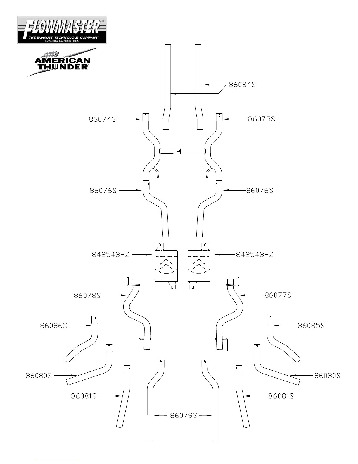
409S® Stainless Steel
Insta llatio n dia gram for:
SYSTEM #817654
1967-1972 GM C10 TRU CKS
2½” HEADER BACK SYSTEM
FLOWMASTER PERFORMANCE EXHAUST
EXHAUST SYSTEMS
 Loading...