

Page 1

Header Installation Instructions:
Part Number: 814110
1965-89 Chevrolet Passenger Car & Wagon
1967-81 Camaro, 1964-87 Chevelle, El Camino
1970-87 Monte Carlo, 1968-79 Nova
409S® Stainless Steel
WARNING: The product accompanying this document is legal only for off-highway use (except in California or
states that have adopted California emission standards), racing use or for use on pre-emission-controlled motor
vehicles/motor vehicle engines (pre-1966 domestic vehicles certified to California standards, pre-1968 domestic
vehicles certified to federal standards and all pre-1968 foreign vehicles), per the manufacturer’s application guide.
Note: Installation of this product requires an adequate work space, general mechanic’s tools, general
mechanical “know how” and a reasonable level of experience. Most auto enthusiasts with these resources will
have little difficulty installing these headers. However, you should carefully read these instructions before
attempting to install these headers. If in doubt, consult a professional mechanic. (Better to do it now than to get
stuck halfway through the installation.)
Check to make sure that you have received the proper parts for your installation. The header number will be
stamped on the engine flange. If you are unsure you have received the proper parts call before you start work.
Be sure to work safe! Whenever you work under the vehicle be sure that it is located on level, solid ground and
is supported by adequate safety stands. Remember: Hot asphalt will not support most jack stands!
Many factors affect the installation of headers, some of which are; broken or aftermarket motor mounts,
accidents that impact the configuration of the frame, and/or the installation of different engines or aftermarket
cylinder heads. If you are not comfortable with welding operations, we recommend that you contact a
professional exhaust system specialist to install your new headers.
Attention Customers breaking in new engines: Due to the extreme heat generated during the break-in
process, the appearance of the ceramic coating may be altered in certain areas. The protection characteristics
and thermal barrier properties of the coating is never compromised. It is recommended that a cast iron
manifold or old set of headers be used for this process.
The purchaser is responsible for following all installation instructions and safety guidelines supplied with your
new Flowmaster Performance Exhaust Product. Flowmaster Performance exhaust assumes no responsibility
for damages resulting from improper operation, misuse, abuse, or lack of reasonable care, or any problems
resulting from incompatibility with other manufacturer’s products.
Flowmaster uses sealing beads on its headers. We have found that when installed correctly, the raised bead
around each port increases the pressure exerted on the gasket directly adjacent to the port and effectively
prevents leaking gaskets. It is normal for the flange to be raised off the cylinder head the thickness of the
sealing bead. It is important when installing the header to install all bolts loosely, and then tighten evenly to
ensure the flat installation of the flange. The torque sequence from one flange to another will vary, but
generally every bolt on a header should be first fit snug, starting from the inside of the flange working out,
alternating from top to bottom so that the bolt connects the flange to the manifold to the point where they barely
touch. Second, using the same inside-out pattern, tighten each bolt until finished. This method will help prevent
leakage and will give the user the best possible performance out of their new set of headers.
Page 2

DISASSEMBLY
1) Place the vehicle in a location where the floor is solid and flat, with adequate lighting. Do not
attempt to work on a hot engine. Heat causes metal to expand and makes removal of fasteners
difficult at best. Disconnect the battery cables from the battery. Raise the front of the vehicle to
obtain adequate access to the bottom exhaust manifold flanges. Use large base jack stands to
support the vehicle. Do not rely on the jack! Block the tires to prevent the vehicle from rolling off of
the jack stands.
2) Disconnect the spark plug wires by grasping and gently twisting the spark plug wire boots. Do not
pull on the wires! Brush or blow off any debris which may have collected around the manifolds or
spark plugs. This will help prevent foreign matter from entering the combustion chamber when the
manifolds are removed. Spray WD-40 or some type of penetrating lubricant on all accessible
exhaust manifold fasteners and fittings before attempting to remove them.
3) Disconnect the head pipes from the exhaust manifolds and remove the manifolds.
4) Remove the alternator, dipstick, dipstick tube, clutch linkage, and oil filter. Remove the starter if
needed. On late model cars, remove the power steering bracket.
5) On cars equipped with air conditioning, unbolt the compressor and lay aside.
6) Some cars may require the removal of the floor board heat shield for adequate clearance.
7) Early models will require a conversion screw-on type filter.
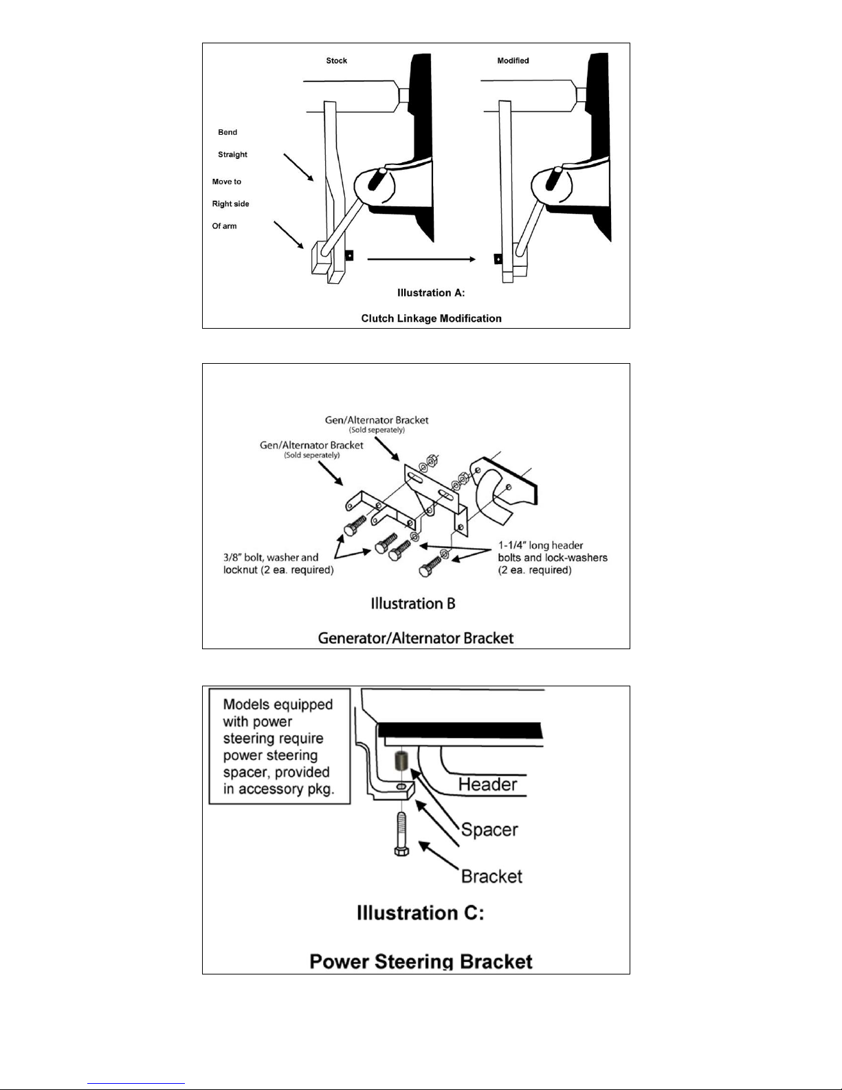
8) The clutch linkage will need to be modified as in Illustration A.
9) Models with the generator/alternator on the left side may need to purchase a set of aftermarket
brackets sold separately. See Illustration B.
10) On some model years it will be necessary to remove the two struts that bolt to the sub-frame.
11) Replace the spark plugs finger tight so that no debris will get into the cylinders during the cleaning
process.
12) Remove any gasket material or carbon deposits that remain on the head surface. The use of a
gasket removal agent will ease the removal of any gasket material. We recommend the use of a
sharp gasket scraper to remove the bulk of material and to finish the operation with a sanding
block to provide a clean flat sealing surface.
13) After cleaning has been completed, remove the spark plugs again.
ASSEMBLY
14) Apply a THIN film of Ultra Copper Hi-Temp Sensor Safe Silicone Sealer to each side of the header
gaskets and stick the gaskets to the header flanges. Masking tape can be used to help hold the
gaskets to the header.
15) Note: Some year models may require the engine to be raised slightly by removing the motor mount
bolt on either side. Use a board between the pan and the jack.
16) Install the headers from the bottom of the vehicle, slide the headers into place and install a bolt at
either end of the header to hold them in place.
Page 3

17) Lower the motor, replace the motor mount bolts and check for header clearance.
18) Using the supplied header bolts and lock washers, apply a small amount of anti-seize to the bolts
and start the most restrictive bolts first. Tighten to a final torque of 35 ft./lbs.
19) Replace the clutch linkage, oil filter, dipstick tube, dipstick and alternator.
20) On late model cars with power steering, use the spacer provided and the long bolt from the stock
exhaust manifold to remount the power steering. See Illustration C.
21) Replace the starter and connect the wires. Reroute the wires as needed for clearance.
22) Using the hardware provided, install the Flowmaster Ball flange connector to the back of the
header and determine the connection to the exhaust. Weld the exhaust system to the ball collector.
23) If the spark plugs have a lot of miles on them, now would be a good time to replace them. If you
replace the spark plugs, make sure to put a small amount of anti-size on the threads.
24) Install the spark plugs and connect the wires to the proper plug. It may be necessary to reroute the
wire to clear the headers.
25) Check to make sure that all wiring, brake lines, hoses, etc. are clear of the headers or any exhaust
component.
26) Make sure all necessary brackets and accessories have been replaced and secured. Reconnect
the negative battery cable.
27) Start the engine and allow it to warm up to operating temperature. Check for any unusual noises or
exhaust leaks. If everything is OK, stop the engine and tighten all bolts while the engine is still
warm. Note: Recheck the header bolts periodically to make sure they have not loosened. Retighten after the first 500 miles and then again at 1000 miles.
IMPORTANT CHECK LIST
Be sure that all brake lines and fuel lines are clear of headers and/or connector pipes.
All spark plug wires, battery cables or other electrical components should be clear of headers and/or
connector pipes.
If dipstick tube has been removed, make sure it is installed properly and that the dipstick has been
replaced.
Double check the tightness of all bolts including brackets and accessories.
PARTS LIST
Qty: Description
(1) Drivers Side Header Assembly.
(1) Passenger Side Header Assembly
(2) Header Gaskets
(2) 3” to 2½” Header Reducer Tube
(2) Ball Connector Flange
(1) Power Steering Spacer
(12) 3/8”-16 x 1” Header Bolts
(4) 3/8”-16 x 2¼” Ball Collector bolts
(4) 3/8”-16 Hex Nuts
(16) 3/8” Lock Washers
(4) 3/8” Flat Washers
(1) Flowmaster Decal
Page 4
Flowmaster Performance Exhaust
Exhaust Systems
 Loading...