

Page 1
DIGITAL PANEL METERS
MODEL LI2X
1
3
/2 Digit
Loop Powered Meter
• 4-20 mA INPUT
1
• 3
/2 DIGIT DISPLAY
• EASY CALIBRATION
AND
INSTALLATION
• LOOP-POWERED
DESCRIPTION
The LI2X 31/2 digit loop-powered meters are
perfect for applications where a simple,
inexpensive display is required and no AC
power is available.And even if the lighting is
poor, the loop-powered backlighting option lets
you see the display under any lighting condition.
This option gets its power from the 4-20
input loop so there is no need for additional
wiring and no batteries to ever change.The
LI2X is housed in a NEMA 4X enclosure, so
it can be installed in just about any nonhazardous area in the plant.
mA
BACKLIGHTING OPTION
• OPERATING
TEMPERATURE RANGE:
-40° TO 85°C
ORDERING INFORMATION
Model Description
LI21-1001 NEMA 4X
Loop-powered Meter
LI22-1001 NEMA 4X
Loop-powered Meter with
Loop-powered Backlighting
10500 Humbolt Street • Los Alamitos, Ca 90720
Tel: (562) 598-3015 • Fax (562) 431-8507
Page 2
LI2X
TOP VIEW END VIEW
A C
B
D
Wall Mounting
Holes Beneath
Cover Screws
E
F
Balance Control
(factory adjust only)
LO Calibration Control
HI Calibration Control
Decimal Point
Jumper Array
Ribbon Cable
Connector
JP1
HI
R9
R 11
LO
++
+
--
-
Loop Power
Supply
Signal Input
Connections
SS
4-20 mA
Transmitter
Screw Terminal Connector
Ribbon Cable
Connector
Display Board
Input Signal Board
Screw Terminal
Connector J5
APPLICATION INFORMATION
SPECIFICATIONS
INPUT: 4-20 mA
DISPLAY: Sharp, 0.5
" high LCD, 3
selectable decimal point.
CALIBRATION: 2 Step; Non-interacting zero and span.
CALIBRATION RANGE: 4 mA input: -500 to +500; 20 mA
input: between 20 to 2000 above 4 mA display.
MAXIMUM INPUT CURRENT: 30 mA
MAXIMUM VOLT A GE DROP: 1.5 VDC @ 20 mA; 3.5 VDC
@ 20 mA with backlighting option.
ACCURACY: ±0.1% of span, ±1 count.
CONNECTIONS: Removable screw terminal block (provided).
OPERA TING TEMPERA TURE RANGE: -40 to 85°C
ENCLOSURE: High impact-resistant ABS plastic body, clear
ABS plastic cover; NEMA 4X,
base. May be provided on back for panel mounting
applications, call factory for details.
LOOP-POWERED BACKLIGHTING OPTION: Factory
installed only. Powered directly off the 4-20 mA loop, no
batteries
input signal
required.The display br ightness will increase as the
current increases.
WARRANTY: 1 year parts & labor.
1
/2 digits, 1999, User
1
/2" conduit hole provided at
SETUP
The only tools needed for calibration are a calibrated current
source and a screwdriver.
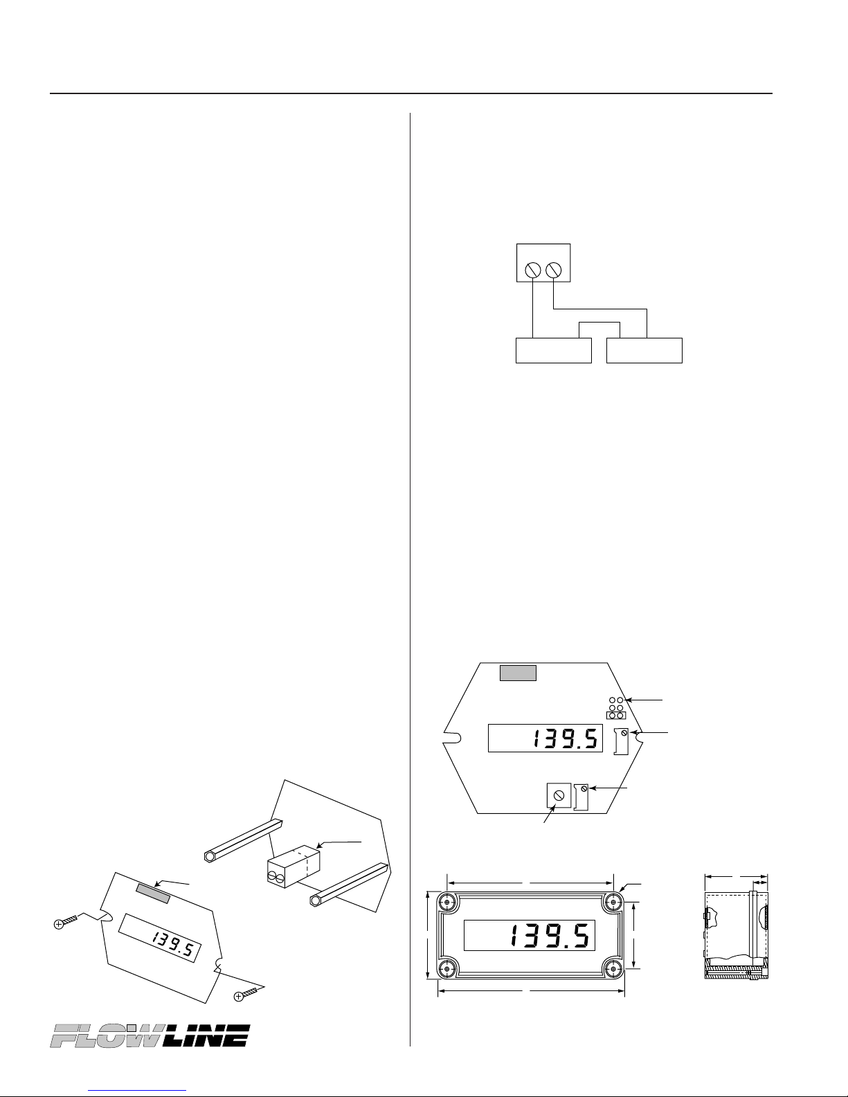
DISASSEMBLY
The removable screw terminal connector is located on the
lower circuit board.To access these input terminals it is
necessary to remove the display board from the input signal
board.This is done by first removing the enclosure cover.
Next,
loosen the 2 screws that hold the display board to the
standoffs. Rotate the display board so the right side comes
off the standoff
from both standoffs. Be careful to avoid contact of the display
with rough surfaces.The display board may be disconnected
from the ribbon cable simply by pulling up on the ribbon
cable connector located above the display.Connect a
mA input signal to terminal J5 located on the input signal
board as shown below. When re-assembling the circuit
boards be careful NOT to over-tighten the screws.
first, proceed to remove the display board
4-20
INSTALLATION
Installation of the LI2X involves removing the display board
and screw terminal connector.It may also be necessary to
remove the input signal board depending on type of conduit
hubs used.
CONNECTIONS
DECIMAL POINT SELECTION
The decimal point jumper array (JP1) is located to the upper
right corner of the display board. Place a jumper across the
bottom pins for a display of 199.9, across the middle pins for
a display of 19.99, and across the top pins for a display of
1.999
CALIBRATION
The LO calibration control (R11) is located below the display
and the HI calibration control (R9) is located to the right of
the display. Apply a 4 mA input signal and adjust the LO
control to display the desired reading. Next, apply a signal
between 16 and 20 mA and adjust the HI control to display
the desired reading. Complete the calibration procedure by
making any minor adjustments to the LO and HI controls.
DIMENSIONS
A. 3.15
B. 4.33
"
"
C. 2.36
D. 3.54
"
"
 Loading...