

Page 1

The LI20 control loop readout is a "go anywhere"
meter.First, there is its freedom from the AC lines.
You may power the LI20 directly from the 4-20 mA
loop.Its 1V drop makes the LI20 usable even in
loops protected by safety barriers.Or you can flip a
switch and power the LI20 from a Iow voltage DC
source with transformer isolation between the DC
power and the signal.
Also, you can put the LI20 anywhere because the
large LCD display makes the LI20 easy to read in all
kinds of lighting from bright sunlight to dark shade.
ORDERING GUIDE
MODEL DESCRIPTION:
NUMBER Loop Powered
LI20-1001 Panel Meter
SPECIFICATIONS
DISPLAY: Sharp, large, 0.5" (12.7mm), high LCD.
±1999(0), (0) may be switched on to display to 19,990.
INPUTS: User Selectable, 4-20mA, 1-5 V
CALIBRATION RANGE: 4 mA, (1V) input: -500(0) to
+500(0); 20 mA, (5V) input: between 20(0) to 2000(0)
counts greater than 4 mA display.
POWER: Two modes field selectable; loop power 4 to 20
mA with maximum voltage drop of 1 V and separate DC
supply, 5 to 25 VDC at 6 mA.Transformer isolation
between signal and power inputs is 500 V in the
separate supply mode.
MAXIMUM INPUT CURRENT: 30 mA, DC
MAXIMUM VOLT A GE DROP: 1 V at 20 mA
ACCURACY: ±0.1% of span, ± 1 count
CONVERSION RATE: 1 Conversion/sec.
OPERA TING TEMPERA TURE RANGE: 0° to +70°C
(32° to +158°F)
ENCLOSURE: 1/8 DIN
WARRANTY: One-year par ts and labor
CONNECTIONS: Removable screw terminal block
10500 Humbolt Street • Los Alamitos, Ca 90720
Tel: (562) 598-3015 • Fax (562) 431-8507
DIGITAL PANEL METERS
PROCESS
CONTROL
LI20
31/2 DIGIT
LOOP-POWERED
Page 2
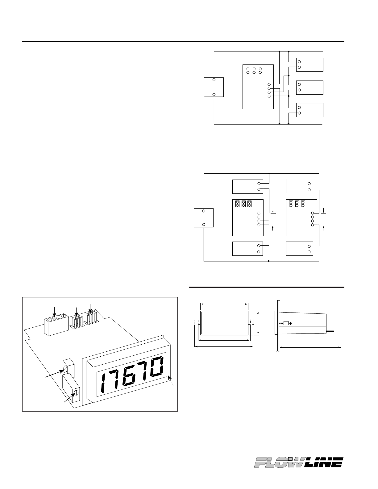
SETUP:
The LI20 may be powered by either of two methods:
directly from the 4-20 mA loop or by a separate DC
supply of between 5 and 25 VDC at 6 mA.Transformer
isolation between signal and power inputs is 500V in the
DC supply mode. Refer to diagrams at right for
connections.
Decimal point or extra zero is activated by a pin array
labeled Z 1 2 3 at the back of the instrument. Place the
jumper over the "Z" pins to illuminate the extra zero, the
"1" pins to illuminate a decimal point in the XXX.X
position etc.
Input signal selection is made by a pin array labeled A B
C at the back of the instrument. For a 4-20 mA control
current input place jumpers over pins A B C. For 1-5 V
input, remove all the jumpers, (to avoid losing the
jumpers, place each jumper over 1 pin of pins A B C.)
CALIBRATION:
The LI20 may be calibrated in its case.The HI and LO
controls are behind the faceplate with the HI control on
the left and the LO control on the right. Remove the
faceplate by inserting a stiff wire in the groove at the
bottom edge of the bezel and prying off the faceplate.
These controls are labeled on the PCB.
Apply 4 mA (1V) to the input and adjust the LO control
for the desired reading.Then apply a signal between 16
and 20 mA (4 and 5V) and adjust the HI control for the
desired reading. Complete the calibration by making any
minor adjustments to the LO and HI displays.
LI20
A. Balanced control; (Factory adjusted only)
B. HI calibration control
C. LO calibration control
D. Decimal point & extra zero pin array
E. Input selection pin array
F. Removable screw terminal block (supplied)
Circuit connection for LI20 monitoring loop current by measuring
voltage across the controller input. LI20 powered by the system
power supply. Power supply circuit (terminals P+ and P-)
completely isolated from signal circuit (terminals S+ and S-).
Here the LI20 adds no voltage drop to the loop.
Circuit connections for LI20 monitoring current loop and
delivering its power from that loop.
NOTES:
A. Panel cutout required - 1.772” x 3.622” (45mm x 92mm)
1/8 DIM
B. Panel thickness - .060”-.250” (1.52mm - 6.34mm)
C. Allow 6 inches (152mm) behind panel
D. Weight: 12 oz. (340 g)
Model LI20
APPLICATION INFORMATION
Power
Supply
Transmitter
Controller
Recorder
P+
P S+
S -
A B C
LI20
+
+
+
+
-
-
-
-
Power
Supply
Transmitter
P+
P -
S+
S -
A B C
LI20
P+
P -
S+
S -
A B C
LI20
+
+
-
-
--
Transmitter
+
+
+
-
ControllerController
1 V Drop
Max
1 V Drop
Max
6" (152mm)
SIDE VIEWFRONT VIEW
Mounting Dimensions
3.82" (97mm)
4.30" (109mm) Installed
4.83" (123mm) Req'd for Inst.
1.88"
(48mm)
A
B
C
F E
D
Page 3

LI20
APPLICATION INFORMATION
 Loading...