

Page 1
EchoWave®
Guided Wave Liquid Level Transmitter
LG10 & LG11 Series Manual
Flowline, Inc. | 10500 Humbolt Street, Los Alamitos, CA 90720 p 562.598.3015 f 562.431.8507 w flowline.com MN300840 REV A10
Page 2

Introduction / Table of Contents Step One
EchoWave
®
utilizes TDR (Time Domain Reflectometry) technology. It is best described as low-energy, highfrequency electromagnetic impulses, generated by the sensor’s circuitry that is propagated along the probe as
it is immerged in the liquid to be measured. Impulses hit the surface of the media and part of the impulse
energy is reflected back up the probe to the circuitry. Level Measurement is calculated from the time difference
between the impulses sent and the impulses reflected. The sensor analyzes the level output as a continuous
measurement reading from its analog output. TDR-Sensors are also known as Guided Radars or Guided Wave
Radars (GWR).
NEW FEATURES
Precise continuous level measurement in one device
Complete galvanic insulation of device electronics from its inputs/outputs and the tank potential (no
problems with electrochemical corrosion protection)
Highly robust measurement due to 3-wire design, innovative signal analysis and disturbance signal
suppression
TABLE OF CONTENTS
Introduction: ...................................................................................................................... 2
Specifications: .................................................................................................... 3-4
Dimensions: .......................................................................................................... 5
About this Manual: ................................................................................................ 6
Getting Started (Setup Overview): .................................................................................... 7
Part Numbers: ....................................................................................................... 8
Probe Length: ....................................................................................................... 9
Measurement Range: ......................................................................................... 12
Distance (Height of Liquid) vs. Volume of Liquid: ............................................... 14
Installation (Mounting Considerations): .......................................................................... 15
Installation Tips: ............................................................................................. 17-20
Wiring (Analog Output): .................................................................................................. 21
Common Wiring to Displays, Controllers & PLCs: ......................................... 23-24
Configuration: ................................................................................................................. 25
Step 1 – Install WebCal Software: ...................................................................... 26
USB Fob Interface: .................................................................................. 27
Step 2 – Measure the Tank: ................................................................................ 28
Step 3 - Sensor Configuration: ............................................................................ 29
Step 4 - Dimensional Entry: ................................................................................ 30
Step 5 - Tank Level Configuration: ..................................................................... 31
Step 6 - Write to Unit: .......................................................................................... 32
Empty Signal Scan: ........................................................................................................ 32
Appendix: ........................................................................................................................ 34
Echo Curve: ........................................................................................................ 34
Sensor Configuration: .................................................................................... 35-37
Volumetric Configuration: ............................................................................... 38-40
Tank Level Confirmation: .................................................................................... 41
Write to Unit: ....................................................................................................... 42
Cutting the Probe: .......................................................................................... 43-45
Troubleshooting: ................................................................................................ 47
Warranty: ....................................................................................................................... 48
| 2 MN300840 REV A10
Page 3

Introduction Step One
ELECTRICAL
Analog output: 4 to 20mA
Total load resistance: < 250Ω
Lower range value: 4.0mA (span 0%)
Upper range value: 20.0mA (span 100%)
Supply voltage: 10 to 30VDC (reverse-polarity protected)
Current consumption: <50mA at 24VDC
Start-up time: <6s
Cable terminals: Terminal block [wires 16 to 26 AWG (solid or stranded)]
MEASUREMENT
Reference condition: (dielectric constant [εr] =80, water surface, tank 01m, DN200 metal flange)
Accuracy: ±3mm
Repeatability: <2mm
Resolution: <2mm
Probe type:
Rod: 4mm
Cable: 4mm, type 7x19
Coaxial: 21.34mm (NPT ½", sch. 40)
Probe length [can be ordered in 5mm (0.2”) increments from the reference point]
Rod: 0.61 to 3.0m (2’ to 9.8’)
Cable: 1.0 to 5.5m (3.3’ to 18’)
Coaxial: 0.61 to 3.0m (2’ to 9.8’)
Probe loading
Rod: Maximum lateral load: 6Nm… (0.2kg at 3 m)
Cable: Maximum tensile load: 5kN
Coaxial: Maximum lateral load: 100Nm… (1.67kg at 6 m)
Top dead band: 100mm (4”)
Bottom dead band: 50mm (2”)
APPLICATION SPECIFICATIONS
Intended Installation:
Rod: Metallic tank or below grade concrete basin
Cable: Metallic tank or below grade concrete basin
Coaxial: Non-metallic, plastic, fiberglass or metallic tank or below grade concrete basin
Dielectric [εr] >1.8
Conductivity: No restrictions
Density: No restrictions
MN300840 REV A10 3 |
Page 4
Introduction Step One
APPLICATION SPECIFICATIONS (CONTINUED)
Process temperature
Rod: F: -40° to 302° C: -40° to 150°
Cable: F: -40° to 302° C: -40° to 150°
Coaxial: F: -40° to 266° C: -40° to 130°
Ambient temperature
Operation: F: -13° to 176° C: -25° to 80°C
Storage: F: -40° to 185° C: -40° to 85°C
Application pressure: -14.5 to 250 psi -1bar to 17.2bar
Rate of level change: 1”/s
MECHANICAL SPECIFICATIONS
Wetted materials:
Rod: 1.4404 / 316L, PEEK
Cable: 1.4401 / 316, PEEK
Coaxial: 1.4404 / 316L, PEEK
Housing materials
Housing rating: IP66, NEMA 4
Cable entries: Single cable entry ½” NPT
Cord grip: ½” NPT, Ferrite Bead included
Cord grip material: Nylon
Cord grip cable
Minimum size: 0.170” (4.3mm)
Maximum size: 0.450” (11.4mm)
Process mount: ¾”NPT (G)
Certification:
Compliance: CE: EN61326-1: 2013 & EN55011 Class A Group 1
CRN
RoHS
CSAus: UL Std. No 61010-3 (3rd edition) & CAN/CSA-C22.2 No. 61010-1-12
c
Aluminum alloy EN AC-AlSi9Cu3 (DIN EN 1706), epoxy
Housing body and cover:
spray coating (~70μm) other alloys and coatings on
request.
Cover o-ring: Silicone rubber (Elastosil R 750/50)
Screws; cover locking screw: 1.4301 / 304 external earth terminal
Screw: Tin plated stainless steel 1.4301 / 304
| 4 MN300840 REV A10
Page 5
Introduction Step One
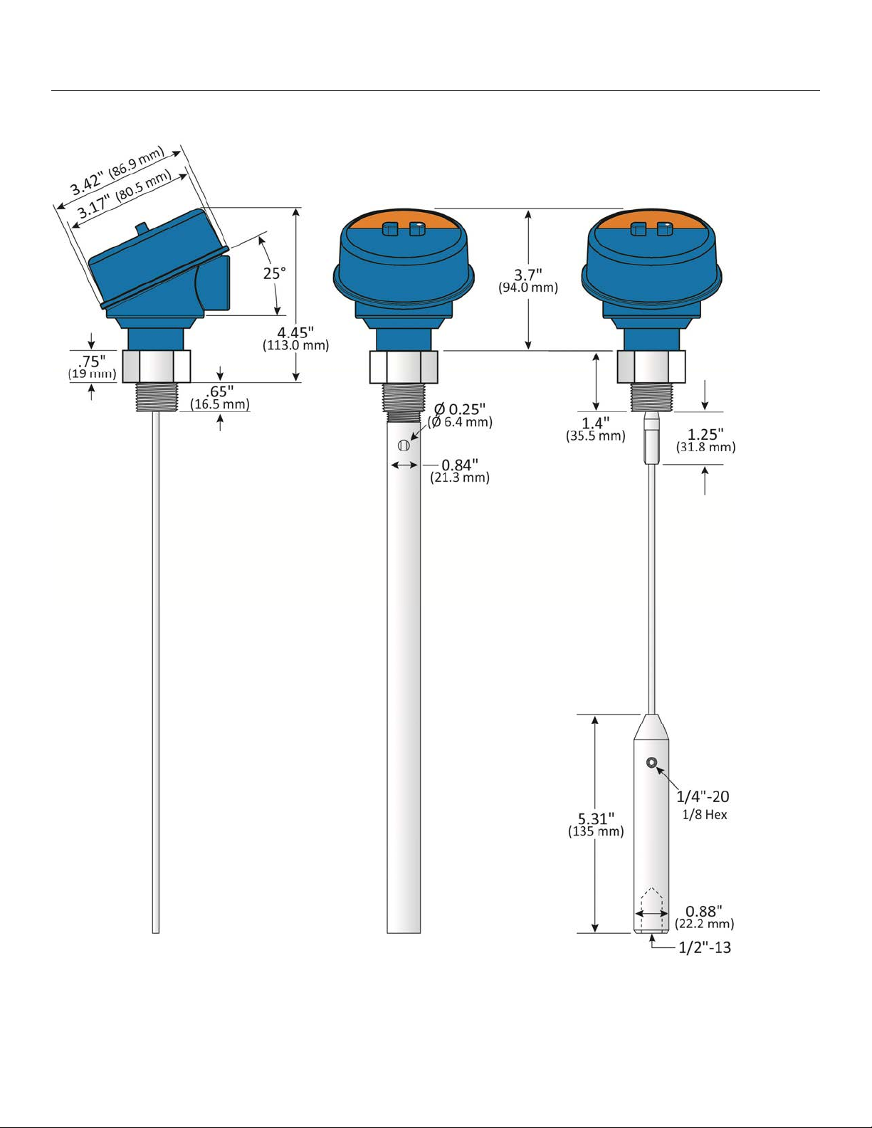
DIMENSIONS
MN300840 REV A10 5 |
Page 6
Introduction Step One
About this Manual: PLEASE READ THE ENTIRE MANUAL PRIOR TO INSTALLING OR USING THIS
PRODUCT. This manual includes information on the EchoWave
from Flowline
®
. Please refer to the part number located on the switch label to verify the exact model
®
series Guided Wave Radar Level Transmitter
configuration, which you have purchased.
User’s Responsibility for Safety: Flowline® manufactures a broad range of level sensing technologies.
While each of these sensors is designed to operate in a wide variety of applications, it is the user’s
responsibility to select a sensor model that is appropriate for the application, install it properly, perform tests of
the installed system, and maintain all components. The failure to do so could result in property damage or
serious injury.
Proper Installation and Handling: Only professional staff should install and/or repair this product. Never
over tighten the sensor within the fitting. Always check for leaks prior to system start-up.
Wiring and Electrical: A supply voltage of 10 to 30 VDC is required to power the EchoWave®. Electrical
wiring of the transmitter should be performed in accordance with all applicable national, state, and local codes.
Material Compatibility: The enclosure is made of metal. Make sure that it is chemically compatible with
the application media.
Enclosure: While the sensor housing is liquid-resistant the EchoWave® is not designed to be operational
when fully immersed. It should be mounted to insure the enclosure does not come into contact with the
application media under normal operational conditions. The probe is designed for full liquid contact.
Note: If using the Flowline
®
LM90-1001 (liquid tight fitting) on the ½” conduit, the cable minimum is 0.170”
(4.3mm) and the maximum is 0.450” (11.4mm).
Handling Static-Sensitive Circuits/Devices: When handling the transmitter, the technician should follow
these guidelines to reduce any possible electrostatic charge build-up on the technician’s body and the
electronic part.
1. Always touch a known good ground source before handling the part. This should be repeated while
handling the part and more frequently after sitting down from a standing position, sliding across the seat
or walking a distance.
2. Avoid touching electrical terminals of the part unless making connections.
3. DO NOT open the unit cover until it is time to calibrate.
Make a Fail-Safe System: Design a fail-safe system that accommodates the possibility of switch and/or
power failure. Flowline
®
recommends the use of a redundant backup system and alarm in addition to the
primary system.
Flammable, Explosive or Hazardous Applications: The EchoWave® sensor is not certified for
application in a hazardous location.
| 6 MN300840 REV A10
Page 7

Getting Started Section Two
SETUP OVERVIEW
Below highlights the initial steps in setting up your sensor for operation.
1. Check Part Number (Section Two)
a. Confirm that the sensor’s part number matches the ordered part number and all components
are provided with the model delivered.
2. Measure Probe & Installation (Section Two)
a. Prior to installation, measure the length of the probe. Confirm that the probe length matches the
actual installation location.
b. If the probe length is too long, refer to Cutting the Probe in Section 8.
c. Understand the location of the sensor’s Measurement Range as well as Minimum Fill-Height
and Maximum Fill-Height settings.
3. Install the sensor (Section Three)
a. Section 3 contains information on the location and mechanical installation of the sensor.
4. Wire the sensor (Section Four)
a. Section 4 contains information on electrical wiring and power requirements for the sensor.
5. Configure Sensor with WebCal™ (Section Five)
a. Section 5 contains information on using the WebCal
®
configuration software.
6. Perform an Empty Scan (Section Six)
a. Section 6 contains information on how to run an empty scan.
b. An empty scan may not be required on a sensor that has a coaxial probe.
MN300840 REV A10 7 |
Page 8
Getting Started Section Two
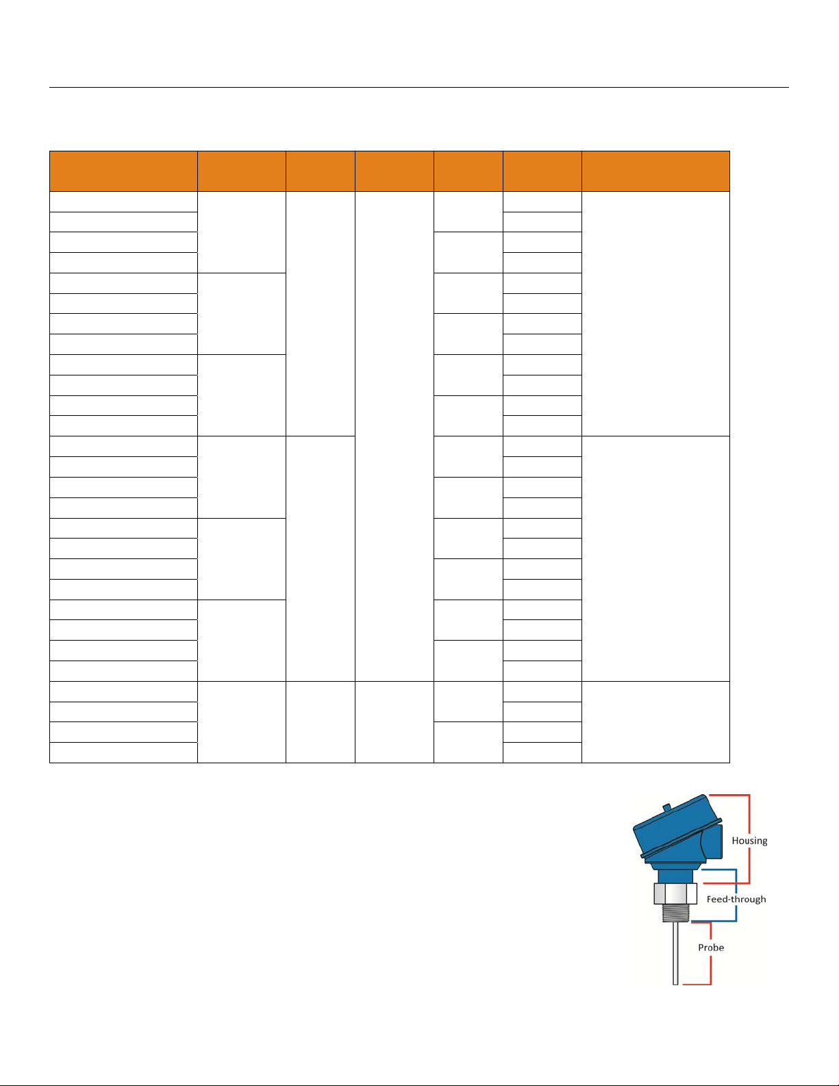
Components: EchoWave
®
is offered in 28 different models. Depending on the model purchased, you may or
may not have been shipped the configuration component shown below.
Part
Number
LG10-0003-00-036
LG10-0003-01-036 Yes
LG10-0013-00-036
LG10-0013-01-036 Yes
LG10-0003-00-072
LG10-0003-01-072 Yes
LG10-0013-00-072
LG10-0013-01-072 Yes
LG10-0003-00-118
LG10-0003-01-118 Yes
LG10-0013-00-118
LG10-0013-01-118 Yes
LG10-1003-00-036
LG10-1003-01-036 Yes
LG10-1013-00-036
LG10-1013-01-036 Yes
LG10-1003-00-072
LG10-1003-01-072 Yes
LG10-1013-00-072
LG10-1013-01-072 Yes
LG10-1003-00-118
LG10-1003-01-118 Yes
LG10-1013-00-118
LG10-1013-01-118 Yes
LG11-2003-00
LG11-2003-01 Yes
LG11-2013-00
LG11-2013-01 Yes
Maximum
Range
3’
(0.91m)
6’
(1.83m)
9.8’
(3m)
3’
(0.91m)
6’
(1.83m)
9.8’
(3m)
18.0’
(5.5m)
Probe
Style
Rod
Coaxial
Cable 316 SS
Mat’l of
Const.
316L SS
Thread Fob Components
¾” NPT
¾” G
¾” NPT
¾” G
¾” NPT
¾” G
¾” NPT
¾” G
¾” NPT
¾” G
¾” NPT
¾” G
¾” NPT
¾” G
The above are standard length models. For custom length probes, add a
length dimension to the end of the part number (i.e. LG10-0003-01-060” or
LG11-2003-01-4.5m). Be sure to indicate the units of measurement.
Coaxial style probe
Cable style probe
1
- includes rod, threaded ½” tube and spacers
2
- includes counterweight
No
No
No
No
No
No
No
No
No
No
No
No
No
No
Housing,
feed-through,
rod style probe
Housing,
feed-through,
coaxial style probe
Housing,
feed-through,
cable style probe
1
2
Quick Start
| 8 MN300840 REV A10
Page 9
Getting Started Section Two
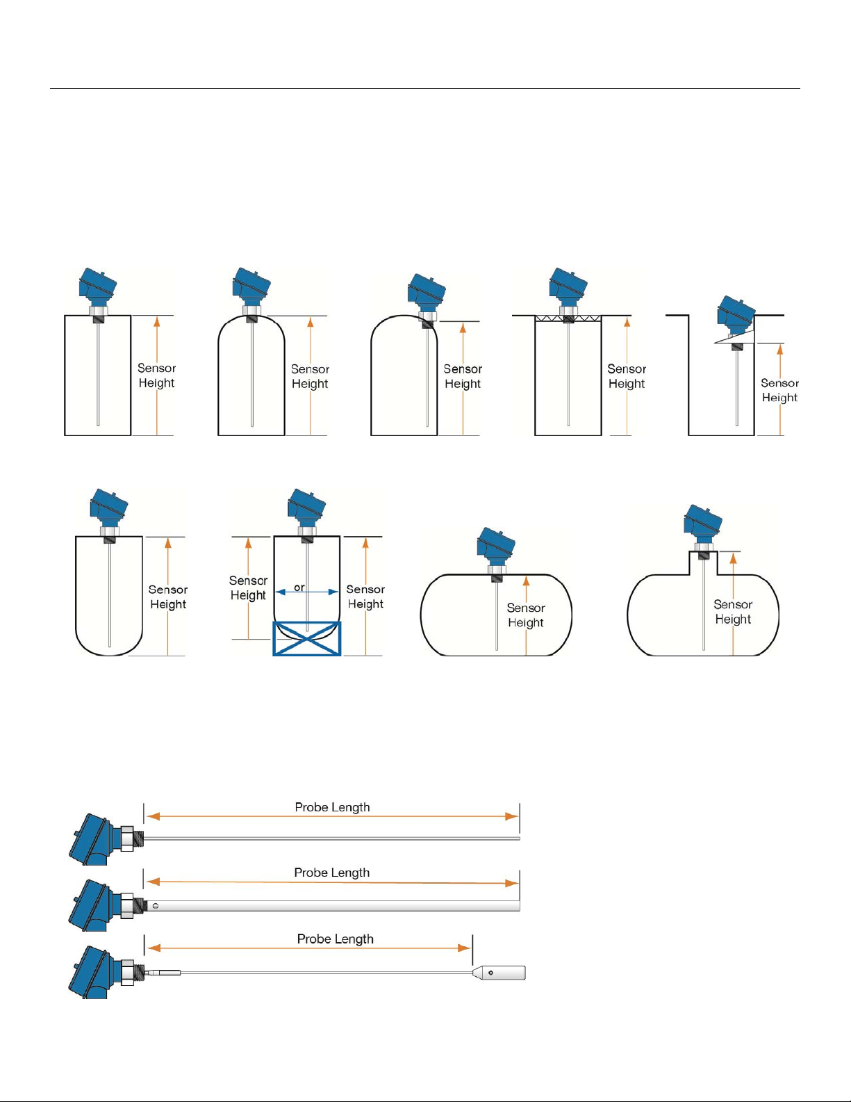
UNDERSTANDING SENSOR HEIGHT
This is a critical setting for EchoWave®. Sensor Height defines the height of the sensor above the bottom of
the tank. The height value must take into account the shape of the tank and any risers, fittings, structures or
extensions associated with the tank or the installation (see examples below). The reference point for definition
of the Sensor Height is always the bottom of the mounting nut.
Simple
Tank
Cone Bottom Raises
Sensor Height
Dome Top Raises
Sensor Height
(SH)
Mounting Fixture
Raises Sensor Height
Sensor Off Center
Changes SH
Simple
Tank
Simple Open
Top Tank
Sensor Extends
into Sump
Lowering SH
Riser Raises
Sensor Height
UNDERSTANDING PROBE LENGTH
The reference point for definition of the probe length [Length] is always the bottom of the threads [bottom of
the feed through (see below)]. Note: This is a different reference location from the Sensor Height. The probe
Length is an important mechanical dimension which is needed to make sure the probe physically fits into the
tank at the anticipated mounting location. Probe length has an influence on the actual measuring range of the
sensor, but it is a different aspect of the sensor.
Rod
Probe
Coaxial
Probe
Cable
Probe
Note: Sensor Height and Probe Length have different reference points for measurement.
MN300840 REV A10 9 |
Page 10
Getting Started Section Two
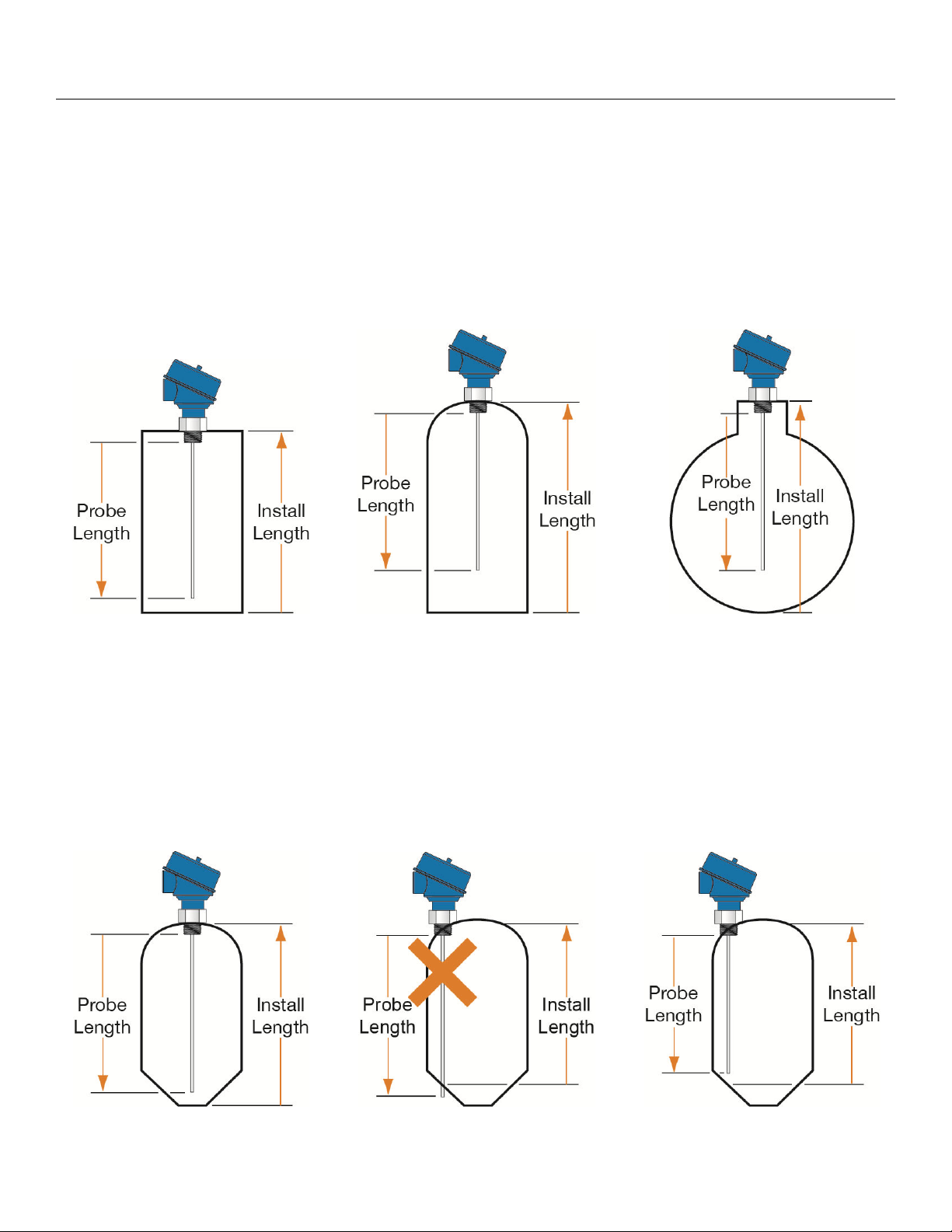
UNDERSTANDING INSTALL LOCATION LENGTH
Measure the space below the actual installation location for the sensor. This distance (install length) must be
greater than the probe length. In many tanks, the install length corresponds to the height of the tank. With
dome top, cone bottom and horizontal tanks, include the added height of the curved surface. Be sure to take
into account the height of fittings, risers, tank flats etc. which may be added for installation. All of the above can
raise the bottom of the probe higher in the tank than what was originally expected resulting in a reduced lowest
level of measurement (see Measurement Range).
Tank with Flat Top
& Flat Bottom
Tank with Dome Top
& Flat Bottom
Horizontal
Tank
CONE AND ROUNDED BOTTOM TANKS
The location of an EchoWave® installed along the top of a dome or cone bottom tank may have an effect on
the installation of the sensor. Be sure to measure from the actual point of installation. Round or cone bottom
tanks will reduce the install height available, depending on install location. If this occurs, either the sensor can
be raised using fittings (see Adding a Riser to Avoid Cutting the Probe) or the probe’s length may be reduced
by cutting the probe (see Cutting the Probe in Section 7).
Install Height >
Probe Length
Install Height <
Probe Length
Install Height >
Probe Length
| 10 MN300840 REV A10
Page 11
Getting Started Section Two
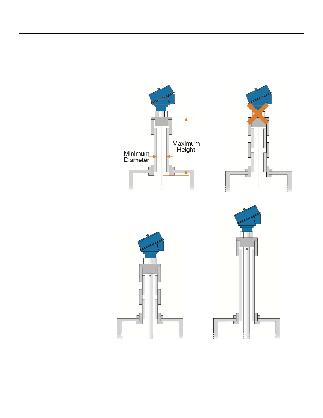
ADDING A RISER TO AVOID CUTTING THE PROBE
In some conditions, a riser may be added to avoid cutting the probe.
Rod and Cable Probes
With the Rod and Cable versions
of the probe, the maximum height
for the riser is 12” (300mm). The
minimum diameter of the riser is 2”
(50mm). The riser must be
metallic in construction using the
least number of fittings
/connections. Note: An Empty
Signal Scan is a requirement so
that the EchoWave
®
can eliminate
the odd geometry created by the
riser.
Least Number of Fittings
Too Many Fittings
Coaxial Probes
With the coaxial probe, there is no
maximum riser height or minimum
riser diameter. This is because the
coaxial shield isolates the physical
changes to the installation from the
sensor’s energy signal. In both
examples, the energy signal
cannot see any changes to the
fitting/connections or from being
installed in an extension that
exceeds the maximum height for
rod and cable probes.
MN300840 REV A10 11 |
Page 12
Getting Started Section Two
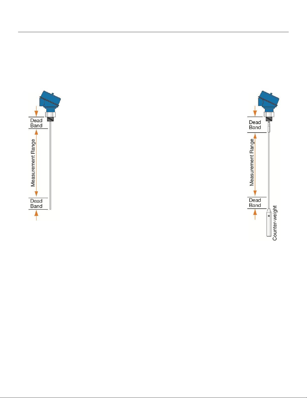
UNDERSTANDING MEASUREMENT RANGE
EchoWave
the presence of unavoidable signal disturbances at both ends of the probe. In these dead band areas the
measurements are non-linear or have reduced accuracy. Therefore, it is not recommended to actually measure
level within these dead band areas. Their length depends on the probe type and the reflectivity
(i.e. dielectric constant) of the liquid to be measured.
®
level transmitters have small dead band areas at both the top and bottom of the probe. It is due to
The Measurement Range of LG10/LG11 series extends between the
top and bottom dead band areas; this is the area in which a sensor will
have the specified measurement performance. It is recommended that
the maximum and minimum levels to be measured in the tank are
actually within the Measurement Range of the sensor. The span
between the lower range value [4mA] and the upper range value [20mA]
of the current output is proportionally equal from 0 to 100% of your
continuous level measurement reading. It is recommended that the span
between these two range values stays within the Measurement Range.
The [Top Dead Band], closest to the threads, is set to 4” (100mm). This
is measured from the top of the threads down to the probe. This is
consistent for all styles of probe. Note: the measurement location for the
Top Dead Band is different to the measurement location for the probe
length.
The [Bottom Dead Band], closest to the end of the probe, is set to 2”
(50mm). This is measured from the end of the probe on rod and coaxial
probes. For cable probes, it is measured from the top of the counterweight. The counter-weight must be included with the dead band as the
sensor’s inactive area.
| 12 MN300840 REV A10
Page 13
Getting Started Section Two
®
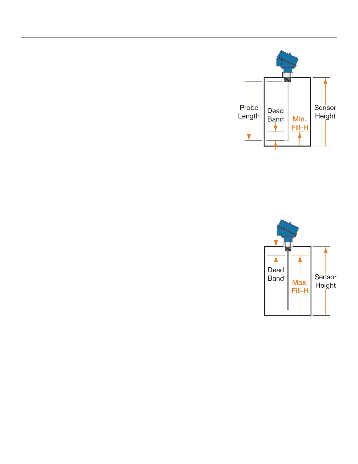
UNDERSTANDING MINIMUM FILL-HEIGHT (PUTTING IT ALL TOGETHER)
EchoWave
from the bottom of the tank to the top of the Bottom Dead Band. As
shipped from the factory, Min. Fill-H is where the 4mA current is located
and is the lowest point on the probe where the sensor can detect a liquid
level. Any point below this position will stop at 4mA. The Min. Fill-H is
influenced by the Sensor Height (SH), Probe Length (P), Height of the
Threads [0.65” (16.5mm)] and Bottom Dead Band.
Min. Fill-H = (SH) – [0.65” (16.5mm)] – (P) + (Bottom Dead Band)
With a cable probe, include the height of the counter-weight.
Switch output to volumetric will allow Min. Fill-H to be set to (0).
If the 4-20 mA output is reversed (20mA at bottom and 4mA at
Note: Because of the bottom dead band, the Minimum Fill-Height can never be at the end of the probe.
Note: The configuration of the sensor (Distance or Volume) will affect the current output at Minimum Fill-
Height. Upon selecting Distance, the current will be set to 4mA at Min Fill-H. However, upon selecting volume,
the current at Min Fill-H will be the calculated based upon 4mA being set at the bottom of the tank [see
Distance (Height of Liquid) vs. Volume of Liquid].
®
has a Minimum Fill-Height (Min. Fill-H), which is measured
top), then the level will max out at 20 mA when the level falls
below the Min. Fill-H.
Understanding Maximum Fill-Height
EchoWave
has a Maximum Fill-Height (Max. Fill-H), which is measured from the
bottom of the tank to the Top Dead Band. As shipped from the factory, Max. Fill-H
defines the 20mA current depicting the highest point on the probe where the
sensor detects liquid level. Any point above this position will stop at 20mA. The
Max. Fill-H is influenced by the Sensor Height (SH), Height of the Threads [0.65”
(16.5mm)] and Top Dead Band.
Max. Fill-H = (SH) – [0.65” (16.5mm)] – (Top Dead Band)
The Max. Fill-H may be decreased to lower the 20mA location, but it cannot
be raised above its original setting.
If the 4-20 mA output is reversed (20mA at bottom and 4mA at top), then
the level will max out at 4 mA when the level rises above the Max. Fill-H.
Note: Because of the top dead band, the Maximum Fill-Height can never be at the bottom of the threads.
MN300840 REV A10 13 |
Page 14
Getting Started Section Two
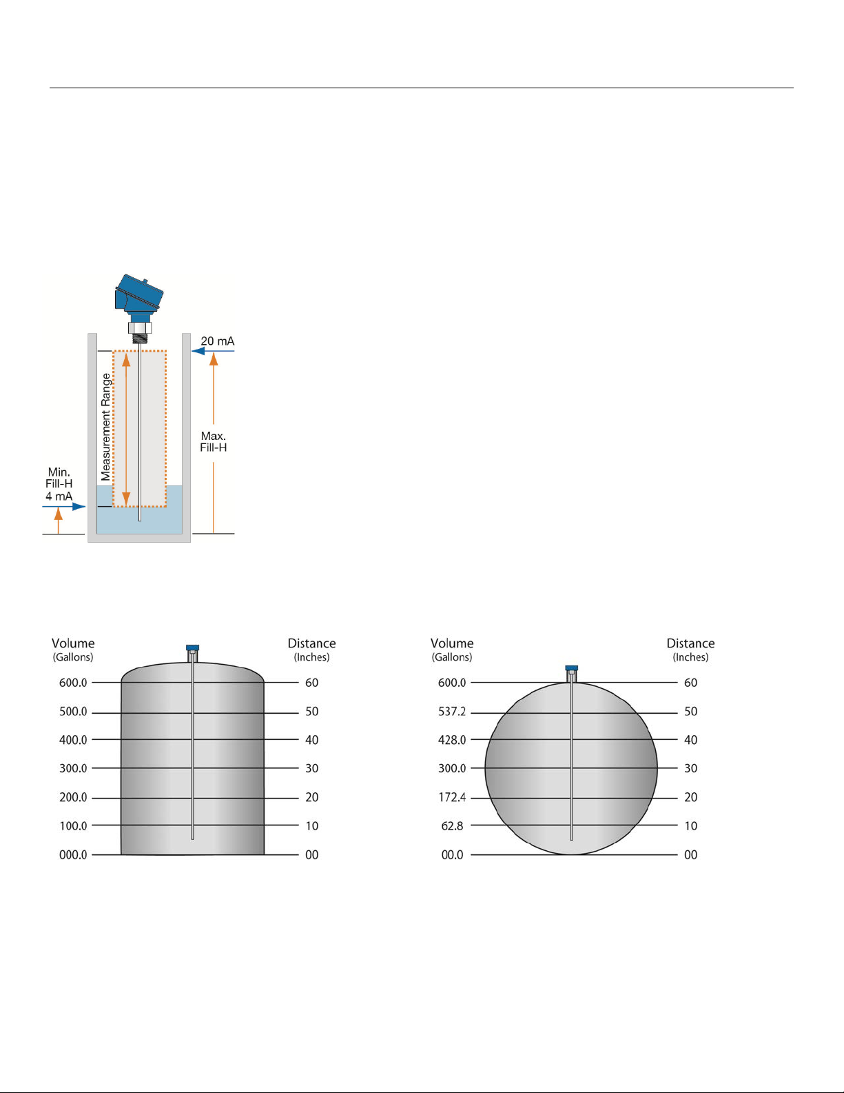
DISTANCE (HEIGHT OF LIQUID) VS. VOLUME OF LIQUID
®
With WebCal
of liquid) or volume of a liquid. The location of the empty current will adjust depending on which configuration
method is selected.
Note: The empty (4mA) location is placed at a different location based upon selecting distance (liquid height)
or liquid volume.
, the LG10/LG11 series can be configured to operate as a device that reads the distance (height
Distance (Height of Liquid): When the EchoWave
®
is configured to read the
distance (height of the liquid), the default for the sensor Empty will be at the
bottom of the measurement range (end of the probe minus the bottom dead
band). This is where 4mA will be set. The default for sensor Full will be at the
top of the measurement range (Top Dead Band), where 20mA will be set. The
20mA can be set by the Maximum Fill-Height.
Volume of Liquid: When the LG10 series is configured to read the volume of
liquid, the output will track the volume of the tank as the level increases and
decreases. Like Distance, the Empty and Full settings will default to the low
and high end of the Measurement Range. The location of the 20 mA can be
adjusted with the Maximum Fill-Height settings. However, the shape of the
tank can influence the current output, depending upon the tank being linear or
non-linear (see below).
Linear Tank Example
Note: In the above illustration, 10” of liquid will
always be equal to 100 gallons of liquid (1” = 10
gallons).
Non-Linear Tank Example
Note: In the above illustration, 1” of liquid does not
equal 10 gallons. The 10” at the bottom represents a
rise of 62.8 gallons. As a change between 10” and
20” represents an increase of 109.6 gallons (i.e.
172.4 gallons – 62.8 gallons).
| 14 MN300840 REV A10
Page 15
Installation Section Three
EchoWave
®
is mounted vertically into the tank via its connection thread. It is then screwed directly into a
standard threaded tank connection, i.e. tank adapter, bushing, weld-in socket, or it can be
screwed into a flange which is connected to a tank nozzle.
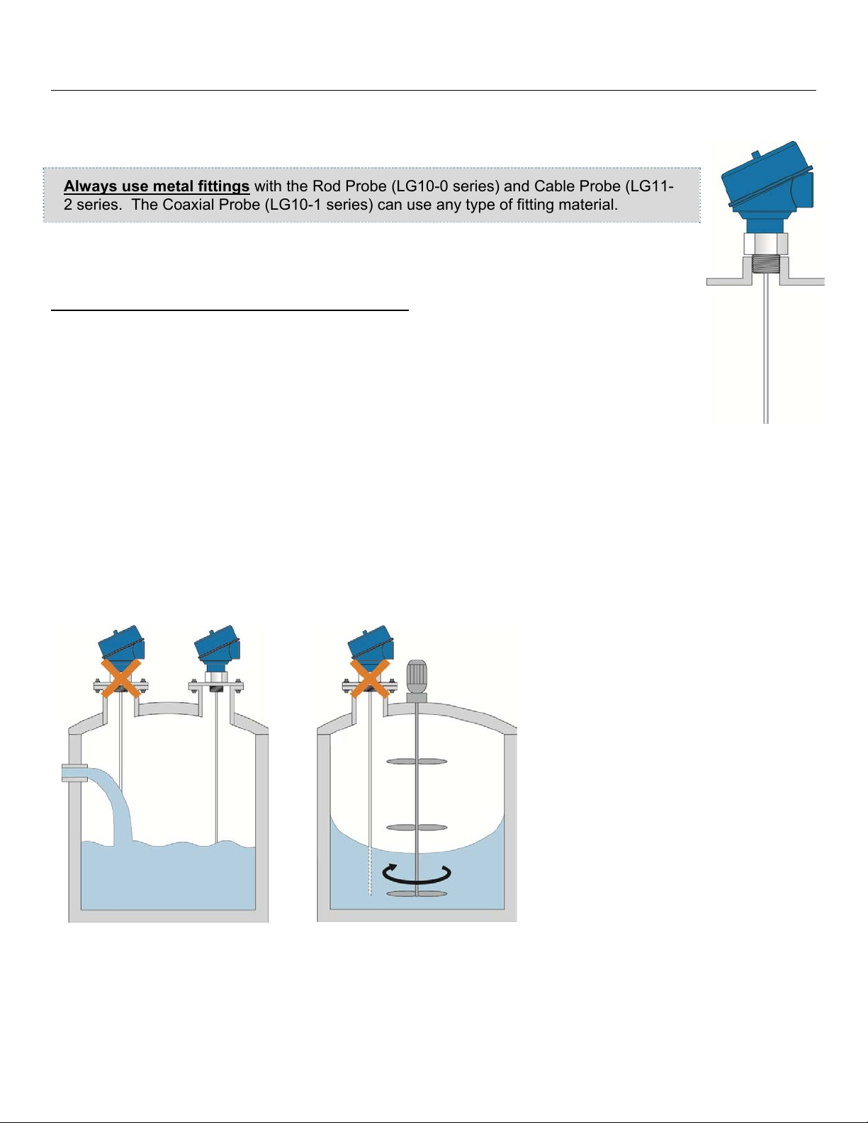
Always use metal fittings with the Rod Probe (LG10-0 series) and Cable Probe (LG11-
2 series. The Coaxial Probe (LG10-1 series) can use any type of fitting material.
LG10/LG11 series should not be welded directly into the tank. Neither should flanges be
welded onto the sensor. Welding on the metal parts of EchoWave
®
will cause serious
damage to the transmitter.
®
Do not lift or handle the EchoWave
probe connection. EchoWave
®
should be handled by the hexagon or the lower section of the
by its probe: This will cause excessive stress on the
housing. Do not screw in the sensor by its housing. It should be tightened only via its
hexagon (wrench size 32mm).
The end user has to ensure proper sealing of the sensor connection; based upon process
conditions, i.e. temperature, pressure and resistance against the process liquid’s
atmosphere.
For NPT thread connections, pressure-tight joints require a sealant directly on the threads.
In the case that the LG10/LG11 series is delivered with a detached probe (cable version only), attach the probe
onto the small threaded stud below the hexagon. Make sure to avoid cross threading or misaligning the
threads.
MOUNTING CONSIDERATIONS
The probes should be installed so that they are not directly impacted by liquids flowing out of the filling inlet.
They should neither touch nor sway towards other objects inside the tank or the tank/nozzle walls; e.g. by
agitator or mixer swirls. In
applications with very strong fluid
movements which can also cause
excessive lateral force on the
probe, it is recommended to
anchor the probe. The anchoring
fixtures are end user supplied.
MN300840 REV A10 15 |
Page 16

Installation Section Three
MOUNTING CONSIDERATIONS (CONTINUED)
The rod and cable probes are suitable for a very wide range of applications
in liquids. However, the signal has a wider detection radius around the
rod/cable. Therefore, it is more responsive for measurement signal
disturbances that are overcome by a few Mounting Considerations (see below)
as well as simple configuration adjustments to the sensor. In most cases it is
enough to activate and utilize the powerful LG10/LG11 series empty signal
scan feature. It works most efficiently on stationary interference targets like tall
and narrow nozzles or close-by objects.
In case a non-stationary interference target is close to the rod probe, like slowly
rotating agitator blades causing problems with the measurement, it is recommended
to use the coaxial probe. In any case, the rod and cable probes should never get in
direct contact with the tank/nozzle wall or other objects in the tank.
Nozzle diameter >2” (50mm) >2” (50mm) +
Rod Cable Coaxial
(1)
Nozzle height <12” (300mm) <12” (300mm) +
Clearance to tank wall or other internal objects >4” (100mm) >4” (100mm)
+
Clearance between probe end and tank bottom >0.1” (2mm) >0.1” (2mm) +
Diameter of bypass chamber / stilling well >1” (25mm) >1” (25mm) +
(2)
Metallic tank or below grade concrete basin + + +
Non-metallic or plastic tank NR NR +
+ = Recommended
(1)
+
= Enough diameter to fit in the coaxial tube (0.677” / 17.2mm)
(2)
+
= Enough diameter to fit in the coaxial tube (0.677” / 17.2mm) with allocated room around the
probe for liquid flow through the bypass chamber / stilling well
NR = Not Recommended
The rod probe is also the recommended probe type for mounting the LG10 series into bypass chambers or
stilling wells. In this case, plastic centering spacers are needed to prevent the probe from contacting the wall.
The cable probe is recommended for installations in tall tanks where limited installation headroom is available.
Its performance characteristics and mounting considerations are similar to the rod probe.
The coaxial probe does not have restrictions regarding mounting position, tank connection, proximity to the tank
wall and other objects inside the tank. The coaxial probe is recommended for installing LG10 series into a nonmetallic tank or open pit.
| 16 MN300840 REV A10
Page 17

Installation Section Three
INSTALLATION TIPS
Tall and Narrow Risers
Rod and Cable probes can be installed in tall and
narrow risers under the following criteria:
Nozzle Diameter must be >2” (50mm),
Nozzle Height must be <12” (300mm),
Riser must be metallic,
An empty signal scan is required after
installation.
Coaxial probes are not affected by tall and narrow
risers.
Difficult Tank or Riser Geometries
Rod and Cable probes must follow the criteria below:
Tall and Narrow Risers criteria must be
followed,
Nozzle diameter remains the same diameter,
Nozzle Diameter does not decrease,
Nozzle Diameter may get larger, but an empty
signal scan is required.
Coaxial probes are not affected by the shape of the
tank or the geometry of the nozzle as the above is not
applicable.
Close to Side Wall or Internal Obstructions
Rod and Cable probes must follow the criteria below:
>4” (100mm) from the side wall,
>4” (100mm) from any objects or obstructions
within the tank,
An empty signal scan may be required after
installation.
Coaxial probes are not affected by the distance from
the side wall or from other objects / obstructions within
the tank.
Moving Probe
Rod and Cable probes must follow the criteria below:
Avoid applications where the movement of the
tank will cause the probe to swing or touch
objects and obstructions in the tank or the side
wall of the tank.
Avoid applications where the tank is
truck/vehicle mounted.
Coaxial probes are not affected by the movement of
liquid within a stationary tank.
MN300840 REV A10 17 |
Page 18

Installation Section Three
INSTALLATION TIPS (CONTINUED)
Liquid Spray
Rod and Cable probes must avoid any liquid that sprays or
pours onto the probe.
Coaxial probes are not affected by liquid straying on parts
that are above the liquid surface. However, avoid installing
probe where liquid will pour onto the probe.
Non-Stationary Documents
Rod and Cable probes follow the criteria below:
>4” (100mm) from any objects or obstructions within
the tank,
An empty signal scan may be required after
installation,
Non-stationary objects must not be moving when
empty signal scan is preformed.
Coaxial probes are not affected by the movement of nonstationary objects, such as mixer blades or pump lifting
chains.
Note: All probes (rod, cable and coaxial) can be affected by
any liquid vortex created by a mixer.
Measurement Readings at the Very Top or Bottom of
Tank
Rod and Cable probes do not have the outer tube and must
adhere to all mounting requirements, specifically:
>4” (100mm) from any objects or obstructions within
the tank, including the bottom of the tank,
Criteria for difficult tank or riser geometries must be
followed.
Coaxial probes can easily be mechanically mounted to
ensure the measurement of liquid up to a full or empty tank.
Because the coaxial is encased within the outer tube, the
sensor is self-contained so other objects or obstructions are
not an issue. This makes raising or lowering the sensor
simple and straight forth.
| 18 MN300840 REV A10
Page 19

Installation Section Three
INSTALLATION TIPS (CONTINUED)
Non-Metallic Tanks
Unlike coaxial, rod and cable probes have no containment
mechanism. This energy must be contained by the tank wall,
requiring that all rod and cable probe sensors be installed in
metallic tanks or within below grade concrete sumps.
Coaxial probes can be installed in any type of tank, including nonmetallic tanks. This is because the outer tube acts as an insulator
preventing the sensor’s energy emanating beyond the probe.
Stilling Wells / Bypass Chambers
Installations within a stilling well or a bypass chamber are
recommended with a rod probe. A metallic pipe is required. A
coaxial probe can be used in a stilling well or bypass chamber if
required. Note: Never use a cable probe within a stilling well or
bypass chamber.
Make sure that the probe does not come into contact with the
inner wall of the stilling well or bypass chamber
o Non-metallic spacers may be required to keep the
probe within the center of the stilling well or bypass
chamber
Make sure the liquid is able to freely fill, empty and that no
residue remains within the stilling well or bypass chamber.
All other mounting criteria must be observed
An Empty Signal Scan may be required after installation
Limited Headroom
When installing in a tank where there is limited space above the top of
the tank, the cable probe is the recommended solution. The cable
probe design allows for the probe to be installed through a small
space above the tank.
The rod and coaxial probes may be installed as long as the probes
are not damaged or bent and as long as the sensor is not held by the
probe (sensor must be held by the head).
All other mounting criteria must be observed.
MN300840 REV A10 19 |
Page 20

Installation Section Three
INSTALLATION TIPS (CONTINUED)
Tall Tanks
The rod and coaxial probes have a maximum insertion length of
9.8’ (3m). For metal or concrete tanks that are taller/deeper, the
cable probe can be used for lengths up to 18.0’ (5.5m).
The maximum length is based from the bottom of the
threads.
o Note: the coaxial probe consists of a rod probe
with a metal outer tube installed around the
original rod. The bottom of the mounting threads
are used as the reference point for measurement.
Side Mount Bracket (LM50 Series)
Rod and Cable probes can be installed with the side mount
bracket under the following criteria:
The side wall or any object / obstructions do not come
within 4” (100mm) from the probe
Any movement of the liquid will not cause the probe to
swing into the side wall or any object / obstruction
The tank must be metallic or a below grade concrete
basin
An empty signal scan may be required after installation
A metal plate of 6” in diameter may be required if there is
no roof to the tank/basin
Coaxial probes are not affected by the side mount bracket.
Probe Too Long
For information on cutting the probe, see Cutting the Probe within the Appendix, Section 7.
| 20 MN300840 REV A10
Page 21

Wiring Section Four
Analog Output (4-20 mA): The analog output of the EchoWave
®
is a sourced 4-20 mA control circuit. The
typical way to use this feature is to connect a positive supply to the (+) input terminal, a negative supply to the
(-) input terminal and to connect the current output out of the 420 (+) terminal. The device that accepts the 420 mA current signal must reference the same negative supply listed above (see diagram below).
SampleWiringDiagram
Diagram will change based upon
the sensor’s configuration, use
WebCal™ to view appropriate
wiringdiagram.
The cabling should be shielded and twisted to minimize EMI interference. Its shield should be connected at either
end and never connected at both ends. Typically 18 to 24 gauge wire is used in this application.
GENERAL NOTES FOR ELECTRICAL CONNECTIONS, USAGE AND SAFETY
Where personal safety or significant property damage can occur due to a spill, the installation must
have a redundant backup safety system installed.
Wiring should always be completed by a licensed electrician.
Protect the sensor from excessive electrical spikes by isolating the power, whenever possible.
Supply voltage should never exceed 30 VDC.
Make sure that the power supply does not have a current more than 2A or that there is 2A rated fuse
in the electrical circuit that energizes the device.
The sensor materials must be chemically compatible with the liquids to be measured.
Design a fail-safe system for possible sensor and/or power failure.
Never use the sensor in environments classified as hazardous.
MN300840 REV A10 21 |
Page 22

Wiring Section Four
WIRE CONNECTIONS
The housing has single cable entry and can be attached to screw plugs, cord grips or conduit with the ½” NPT
thread. Note: the customer must confirm the suitability of those connectors for the specific application
requirements and cabling; and replace them when necessary. IP66-rated screw plugs and cord grips have to
be properly mounted and tightened around cable of suitable type and diameter to ensure the IP66 rating of the
housing.
Note: A liquid-tight cord grip and ferrite bead are included with the
sensor (see Specification Section for cord grip data).
Note: Always include the ferrite bed when using the cord grip or
when using non-metallic conduit.
Note: Always shield the signal wire per instructions on the wiring diagram.
Conduit Connection Cord Grip (Liquid Tight)
Ferrite Bead
Liquid-Tight Cord grip
Avoid Condensation in the Conduit
You can give your instrument additional
protection against moisture penetration by
leading the conduit connection or cable
downward in front of the cable entry.
Condensation in the conduit will thus not enter
the sensor enclosure.
| 22 MN300840 REV A10
Page 23

Wiring Section Four
COMMON WIRING TO DISPLAY, CONTROLLERS & PLC’S
Below is a quick review of wiring the EchoWave® to common display, controllers and PLC’s.
DataView™ LI55 Series
Level Controller
DataLoop™ LI23 Series
Level Indicator Without Backlight
Commander™ LI90 Series
Multi-Tank Level Controller
DataLoop™ LI23 Series
Level Indicator with Backlight
Note: 4-20 mA signal wire requires shielding (power supply wires may use the same shielding as the signal
wire). Shield wire can be connected at either end. Never connect shield wire at both ends. EchoWave is a 3wire transmitter and should never be wired as a 2-wire loop device.
MN300840 REV A10 23 |
Page 24

Wiring Section Four
COMMON WIRING TO DISPLAY, CONTROLLERS & PLC’S (CONTINUED)
Below is a quick review of wiring the EchoWave
®
to common display, controllers and PLC’s.
Generic Loop
Powered Display
DataPoint™ LC52 Series
Level Controller
(JWB mode)
Generic PLC
Note: LC52 shipped from factory with jumper in JWA
mode. Jumper must be switched to JWB mode for
operation with the EchoWave
®
.
Note: 4-20 mA signal wire requires shielding (power supply wires may use the same shielding as the signal
wire). Shield wire can be connected at either end. Never connect shield wire at both ends. EchoWave is a 3wire transmitter and should never be wired as a 2-wire loop device.
| 24 MN300840 REV A10
Page 25

Configuration Section Five
EchoWave
®
can be configured before installation or within the tank. The transmitter features non-volatile
memory, so any setting configured before installation will not be lost when the sensor is powered down. To
configure, follow the steps below:
1. Install WebCal
a. Go to www.flowline.com/webcal-software/
b. Review how USB
®
Software
®
and select language version.
Fob interfaces with EchoWave® and your computer.
2. Measure the Tank
a. Begin by measuring the key tank and fitting dimensions.
b. Correct tank dimensions will result in accurate sensor measurement.
3. Sensor Configuration
a. Configures Loop Fail-Safe, Output at Empty, Startup Condition & Dielectric Range for the sensor.
4. Dimensional Entry
a. Distance Mode (default).
i. Basic information for operation including Sensor Height, Probe Length, Max. Fill-Height.
5. Tank Level Confirmation
a. Confirm the values are accurate for the application.
6. Write to Unit
a. Uploads configuration into the sensor.
b. Access to a customer wiring diagram.
MN300840 REV A10 25 |
Page 26

Configuration Section Five
STEP 1 – INSTALL WEBCAL® SOFTWARE
EchoWave® is configured through WebCal®*, a PC software program. WebCal® is a free download from
®
Flowline’s website. You must download and install WebCal
(version 6.5 or greater) prior to plugging in
the USB® Fob. Please go to flowline.com/webcal-software, and select your language version.
WEBCAL® SYSTEM REQUIREMENTS
Windows® XP, Vista, 7, 8, 10
32 or 64-bit system
1 USB
®
2.0 port
10 mB hard drive space
256 mB RAM
Internet connection
* For complete information on the WebCal
®
software, please refer to the WebCal® manual located at
flowline.com/webcal-software.
| 26 MN300840 REV A10
Page 27

Configuration Section Five
USB® FOB INTERFACE
EchoWave
Before plugging your Fob into your computer’s USB
6.5 or greater) on your computer.
Connect the red, green, white and black terminals on the Fob to the corresponding terminals within the
EchoWave
®
communicates with WebCal® (version 6.5 or greater) through a USB® interface called a Fob.
®
. Tighten the screws on the terminals and plug your Fob into the USB® port of your computer.
®
port, be sure that you have installed WebCal® (version
WIRING IS IDENTICAL FOR ALL SERIES OF ECHOWAVE
The maximum cable distance between the computer and EchoWave® is 15’. This only applies when
configuring the EchoWave
Once EchoWave
®
is configured and prior to installation, disconnect all wires from the center two terminals
®
.
®
to prevent a short of the configuration circuit
Note: When using the Fob, do not add VDC power. The Fob, when connected to the computer, will provide
®
the required power to the EchoWave
* For complete information on the WebCal
.
®
(version 6.5 or greater) software, please refer to the WebCal®
manual located at flowline.com/webcal-software.
MN300840 REV A10 27 |
Page 28

Configuration Section Five
STEP 2 - MEASURE THE TANK
Measuring the tank is one of the most important aspects in
configuring the sensor. When measuring the tank, take
into account the location of the sensor with respect to
fittings, risers, dome tops and bottoms, and identify where
the measurements are taken from the sensor. The Sensor
Height is influenced by the installation location. Sensors
mounted along the sloped portion of the tank will result in a
lower (HEIGHT) value. On the other hand, sensors
installed in risers/nozzles will result in a higher (HEIGHT)
value.
The basic measurements (Sensor Height, Probe Length, Max. Fill-H and Man. Fill-H) for configuration are
described below:
1. SENSOR HEIGHT - Distance from the Top of Sensor’s
Threads (sensor’s measurement location) to the bottom
of the tank.
a. The Sensor Height is typically set to the bottom
of the tank.
b. This setting determines the 4mA location.
2. PROBE LENGTH – Actual physical length of probe.
a. The Probe Length is measured from the bottom
of the threads to the end of the probe.
3. MAX. FILL-H - Distance from the bottom of the tank to
the level of liquid where the tank is full.
a. This setting determines the 20 mA location.
b. The MAX. FILL-H is typically set to the liquid full
level.
c. 20mA cannot be set within the sensor’s upper
dead band [4” (10cm) from top
of the threads].
d. Largest MAX. FILL-H value will be as follows:
Largest MAX. FILL-H = SENSOR HEIGHT – 4” (10cm)
4. MIN. FILL-H - Distance from the bottom of the tank to the lowest portion of the probe when level can be
detected.
a. This setting determines the 4 mA location.
b. The MIN. FILL-H is automatically calculated by WebCal
®
.
c. 4mA cannot be set within the sensor’s lower dead band [2” (5cm) from end of the probe].
d. Smallest MIN. FILL-H value will be as follows:
Smallest MIN. FILL-H = SENSOR HEIGHT – Probe Length - 2” (5cm)
| 28 MN300840 REV A10
Page 29

Configuration Section Five
With EchoWave
Follow steps 3 to 6 to configure the transmitter using WebCal
open the help menu of WebCal
WebCal
®
, please contact a Flowline® application engineer at (562) 598-3015. Note: For complete information
on the WebCal
STEP 3 – SENSOR CONFIGURATION
®
connected to your computer, open the WebCal® software by clicking on the WebCal® icon.
®
for more instructions on WebCal®. If you need additional assistance using
®
software, please refer to the WebCal® manual located at flowline.com/webcal-software.
®
. Click “Help” in the lower right hand corner and
Configures the Loop Fail-Safe, Output at Empty, Startup Condition, Probe Type and Dielectric Range.
Out of Range
Flowline suggests setting the Loop Fail-safe to
HOLD Last Value in application where the liquid
level falls below the end of the probe or rises
above the Max. Fill-H.
If the level only falls below the end of the
probe, then EMPTY can be used.
If the level only rises above the Max. Fill-H,
then FULL can be used.
Note: Never allow the liquid to rise into the top dead band of the sensor (within 4” from the top of the
threads.
MN300840 REV A10 29 |
Page 30

Co
n
P
N
v
o
S
e
y
y
c
SdP
f
e
w
S
T
f
e
n
r
m
t
f
t
e
M
e
u
e
s
a
m
e
m
c
p
m
c
h
O
a
f
o
u
m
e
w
u
C
H
p
r
d
s
b
a
e
:
U
e
b
e
a
d
o
c
n
e
s
m
e
t
M
S
e
f
T
H
b
o
y
e
e
e
STE
figurati
4 – DIMEN
n
IONAL EN
RY:
ection Fiv
Distanc
change i
categor
settings
settings
Mode (de
n liquid leve
. For Volum
ou must e
an be ente
ensor Heig
istance fro
robe Leng
o
the probe
F
ill-Height:
p
osition to th
ault): Outp
l will reflect
tric output
ter for Dist
ed on the
ht: Sets th
the Empty
h: Sets the
o the botto
Sets the lo
Full level
t of sensor
linearly to t
, refer to V
nce Mode
ain configu
location o
level positi
physical len
of the mo
ation for 20
osition (se
is based on
e current o
LUMETRI
re Sensor
ration scree
the sensor
n to the To
gth of the p
nting threa
A. It is ba
below).
the distanc
tput. Note
CONFIG
eight, Prob
n.
above the
of the Thr
obe. It is b
s.
ed on the
(height of
Most appli
RATION o
Length an
ottom of th
ads of the
sed on the
istance fro
liquid) in th
ations will
page ??.
d Max Fill-
tank. It is
ensor (see
distance fr
the Empt
tank. Any
all into this
he three
. All three
ased on th
below).
m the end
level
ote: In th
alue will al
Distance
ays indicat
ode, the 4
the distan
A location
e the 4mA
ill always
location is
e 2” from th
bove the b
e end of th
ttom of the
probe. Th
ank.
Min-Fill-H
| 30
N300840 REV A1
0
Page 31

Configuration Section Five
STEP 5 – TANK LEVEL CONFIRMATION:
Verify the Height Units, Sensor Height, Probe Length, Maximum Fill-Height & Minimum Fill-Height. All values
were calculated in the previous Dimensional Entry window.
STEP 6 – WRITE TO UNIT:
This WebCal®* operation uploads configuration into the sensor. Other features in the section include providing
a custom wiring diagram specific to the signal output and saving the configuration file to your hard drive.
VolumetricSensorOutput
TheVolumetricModebutton will
be highlighted in Blue when a
volumeoutputisselected.
* For complete information on the WebCal
flowline.com/webcal-software.
MN300840 REV A10 31 |
®
software, please refer to the WebCal® manual located at
Page 32

Empty Signal Scan Section Six
EMPTY SIGNAL SCAN
The Empty Signal Scan is a powerful disturbance signal suppression feature of EchoWave®. The sensor scans
its entire probe length for any disturbance/interference signals within the application that could potentially be
misinterpreted as level readings by memorizing and suppressing them during operation. Therefore, the
LG10/LG11 series only recognizes the actual level signals caused by the liquid being measured.
The Empty Signal Scan is intended for the rod & cable probe, since its signal has a wider detection
radius around the probe making it more responsive for measurement signal disturbances. An
Empty Signal Scan is typically not required for the coaxial probe.
The Empty Signal Scan works most efficiently on stationary interference targets like tall and narrow risers or
close-by objects/obstructions. To enable an Empty Signal Scan, the EchoWave
®
has to be mounted in its final
position. The tank has to be completely empty. This will ensure a reliable identification of the actual
disturbance signals only. In case there are non-stationary interference targets close to the rod probe (slowly
rotating agitator blades or streams of liquid filling into the tank), it is recommended to use the coaxial probe.
ACTIVATE EMPTY SIGNAL SCAN
When EchoWave® is shipped, this feature is deactivated. To initiate a
Empty Signal Scan, use the following instructions:
1. Make sure the LG10/LG11 series is installed in its final
installation position.
2. Make sure the liquid is at its lowest level (empty).
a. Performing an Empty Signal Scan when the tank is not
empty will create an incorrect scan. It can affect the
sensors performance especially at liquid levels below the
Empty Signal Scan tank level.
3. Press and hold the SCAN button for 6 seconds.
a. The LED will begin to flash Orange indicating the empty
signal scan has begun, release the button.
b. Upon completion of the empty scan, a solid green LED will return
c. If the empty scan is not successful. The LED will flash red
ERASE EMPTY SIGNAL SCAN
If there is a need to erase or turn off the Empty Signal Scan, perform the following: First remove power to the
EchoWave
®
. Next, hold down the SCAN button while applying power to the sensor. When the LG10/LG11
series acquires a signal (LED will flash Green), the disturbance signal scan will be erased.
No other setting or functions will be affected when this step is preformed.
The Empty Signal Scan cannot be retrieved once erased.
A new disturbance signal scan must be preformed for this function to operate again.
®
The Empty Signal Scan can also be erased using WebCal
software. Please refer to the instructions on the
following page.
| 32 MN300840 REV A10
Page 33

Empty Signal Scan Section Six
VIEWING THE EMPTY SIGNAL SCAN
The Empty Signal Scan can be viewed with the WebCal
consult a Flowline
®
representative for reviewing of the signal data. To view, follow the directions below:
1. Activate an Empty Signal Scan (see instructions in Empty Signal Scan, Section 6).
2. Connect EchoWave
®
to WebCal® software via Fob
3. Click on Diagnostics Tab on the main WebCal
4. In the Select Signal Data pull down, select Empty Signal Scan.
5. The Empty Signal Scan will be displayed in the window.
®
®
screen
software (version 6.5 and greater). Note: Always
ERASE EMPTY SIGNAL SCAN WITH WEBCAL®
If there is a need to erase or turn off the empty signal scan, perform the following:
1. Disconnect the sensor from the application wiring.
2. Connect EchoWave
3. Click on Diagnostics Tab on the main WebCal
®
to WebCal® software via Fob.
®
screen.
4. Click on Erase Empty Signal Scan.
MN300840 REV A10 33 |
Page 34

Appendix Section Seven
ECHO CURVE
This function displays the primary echo return(s) that the sensor is seeing graphically as well as the location
and amplitude of the return(s). It can be used to confirm the correct level reading by the sensor or to
troubleshoot any false signals. There is a two step process involving the creating and viewing of an Echo
Curve. Note: Always consult a Flowline
#1 - CREATE AN ECHO CURVE
To create an Echo Curve, use the following instructions:
1. Make sure the LG10/LG11 series is installed within the actual
application.
a. Echo Curve will not provide any useful information when
placed outside of the application.
2. Press and hold the SCAN button for 1 second (LED will turn off),
then release.
3. Echo Curve is completed.
a. To view, you must connect the sensor to WebCal
Note: LG10/LG11 series can store a single Empty Signal Scan and a single
Echo Curve.
®
representative for reviewing of the signal data.
®
.
#2 - VIEWING THE ECHO CURVE
The Echo Curve can be viewed with the WebCal® software (version 6.5 and greater). To view, follow the
directions below:
1. Create an Echo Curve (see
instructions above).
®
2. Connect EchoWave
WebCal
®
software via Fob
3. Click on Diagnostics Tab on
the main WebCal
to
®
screen
4. In the Select Signal Data pull
down, select Echo Curve.
5. The Echo Curve will be
displayed in the window.
| 34 MN300840 REV A10
Page 35

Appendix Section Seven
This section of WebCal
®
is where you select the sensor configuration settings. Start from the top and work to
the bottom, choosing the sections that are applicable to your configuration. All configuration settings must be
selected before you can Write to Unit.
SENSOR CONFIGURATION
LOOP FAIL-SAFE
This feature allows you to select the fail-safe current output if the
sensor looses echo confidence (LOST). When the sensor regains
echo confidence, the output current will revert back to the current level
condition.
Hold Last Value - The output will remain in the same state as
the last validated echo detected. Example: If the output was
6.7mA just prior to the lost signal, the sensor will continue to
output 6.7mA until echo confidence is regained.
Empty - The output will revert to the current value for an
empty condition. When 4 mA at Bottom is selected, the
sensor will output 4 mA during a fail-safe condition. If 20 mA
at Bottom is selected, the sensor will output 20 mA during a
fail-safe condition.
Full - The output will revert to the current value for a full
condition. When 4 mA at Bottom is selected, the sensor will
output 20 mA during a fail-safe condition. If 20 mA at
Bottom is selected, the sensor will output 4 mA during a failsafe condition.
Overfill (21mA) - The sensor will output 21mA during a fail-
safe condition.
Overfill (22mA) - The sensor will output 22mA during a fail-
safe condition.
Note: Right click on any item to open the help menu. To reset the configuration table, press the Clear Screen
button.
Note: Choose Hold Last Value setting when your
Falling Below Probe
Rising Above Max. Fill-H
application level either falls below the end of the
probe or rises above the Max. Fill-H setting. An
alternative solution is to choose Empty setting if the
level only falls below the end of the probe or
choose Full if the level rises above the Max. Fill-H.
Choose Hold Last Value
or Empty
Choose Hold Last Value
or Full
MN300840 REV A10 35 |
Page 36

Appendix Section Seven
SENSOR CONFIGURATION (CONTINUED)
OUTPUT AT EMPTY
This feature allows you to select the orientation of the 4 to 20mA
output (4 to 20 mA or 20 to 4 mA). Choose which output setting best
fits the application. Factory default is 4mA at bottom and 20mA at top
as this configuration scenario is an industry standard. When
connecting your sensor to a display, you must account for your output
orientation setting.
4mA at Bottom - The output current will be 4mA when the
sensor measures an empty tank and 20mA when the sensor
measures a full tank.
20mA at Bottom - The output current will be 20mA when the
sensor measures an empty tank and 4mA when the sensor
measures a full tank.
STARTUP CONDITION
This feature allows you to select the startup current when power is
first applied to the sensor. The sensor will consume the selected
power while it is acquiring the liquid level. When the correct level
has been identified, the output will adjust to the level output. Use
this feature to avoid false alarms with the controller when power is
first applied to the sensor.
Empty - The current output will revert to the selected current
value for an empty condition.
o 4 mA at Bottom - The sensor will output 4 mA while
the sensor powers up.
o 20 mA at Bottom - The sensor will output 20 mA while
the sensor powers up.
Mid Tank (12 mA) – The sensor will output 12 mA while the
sensor powers up.
Full - The output will revert to the selected current value for a
full condition.
o 4 mA at Bottom - The sensor will output 20 mA while
powering up.
o 20 mA at Bottom - The sensor will output 4 mA while the
sensor powers up.
Overfill (22mA) - The sensor will output 22mA while the
sensor powers up.
Note: Right click on any item to open the help menu. To reset the configuration table, press the Clear Screen
button.
| 36 MN300840 REV A10
Page 37

Appendix Section Seven
SENSOR CONFIGURATION (CONTINUED)
PROBE TYPE
This feature allows you to select the type of probe attached to the
feed-through. It is critical to select the correct type of probe.
Rod - Recommended for installations in liquids, in bypass
chambers and stilling wells (when combined together with
the rod emulate a coaxial probe).
Cable - Recommended for installations in tall tanks and
where limited headroom is available.
Coaxial - Recommended for the use with clean liquids only.
It cannot be used with viscous, crystallizing, adhesive,
coating, or sticky liquids; fibrous liquids, sludge, slurry, pulp
DIELECTRIC RANGE
This feature allows you to select the dielectric range, which sets the
amplitude threshold within the sensor.
or any liquids containing solid particles.
Water based media (water, H2SO4, HCl)
o 40 to 100
o 20 to 39.9
o 10 to 19.9
Varying dielectrics (Alcohols, Ethyl Acetate, Caster Oil)
o 9 to 9.9
o 8 to 8.9
o 7 to 7.9
o 5 to 5.9
o 4 to 4.9
o 3 to 3.9
o 6 to 6.9
Typical Hydrocarbons (Diesel Fuel, Mineral Oil, Solvents)
o 2 to 2.9
Note: Only change the probe type when the probe has been physically changed. Never change this setting to
improve sensor performance. This will only cause issue with the operation of EchoWave
®
. Right click on any
item to open the help menu. To reset the configuration table, press the Clear Screen button
Note: It is very important to select the correct range for the dielectric value of the liquid. Choosing an incorrect
range will affect the performance of the sensor. Reference a website such as http://flowline.com for dielectric
information.
Note: Right click on any item to open the help menu. To reset the configuration table, press the Clear Screen
button.
MN300840 REV A10 37 |
Page 38

Appendix Section Seven
VOLUMTRIC CONFIGURATION
The sensor may be configured in volumetric
units (Gallons or Liters) or Distance (Height
of Liquid) units (inches, cm, feet or meters).
WebCal
Liquid) with units of Inches. To change
units or change from Distance to Volume,
press the Volumetric Mode button as
located near the center of the window.
Note: The Volumetric Mode button will be
highlighted in Blue when a volume output is
selected.
®
will default to Distance (Height of
| 38 MN300840 REV A10
Page 39

Appendix Section Seven
Shape Selection Window: This window will shows the different tank shape options available in WebCal
®
.
Vertical Cylinder
Vertical Cylinder with Cone Bottom
Horizontal Cylinder with End caps
Horizontal Cylinder with Spherical Ends
Spherical
Rectangular
Strapping Table – Use this feature for manual entry
of measured tank distances and volumes.
Select any of the above tank shapes and press OK to
confirm.
Dimensional Entry - Vertical Cylinder Example
Choose the Sensor Output Units as Distance or Volume. After choosing the Sensor Output Units, select the
units of measurement in the pull down to the left.
Distance Volume
Inches
Cm
Feet
Meters
Distance – Sensor Output Units (Vertical Cylinder Example)
Enter the dimensions of the tank. You must
enter data in all fields shown.
Sensor Height: Distance from the bottom of
the tank to the top of the threads.
Max. Fill Height: Distance from the bottom
of the tank to the operational full level of
liquid (20mA). This setting defines the
location of full current output and is the top of
the sensor’s measurement range.
Min. Fill Height: Distance from the bottom of
the tank to the operational empty level of
liquid (4mA). This setting defines the location
of empty current output and is the bottom of
the sensor’s measurement range.
Units of Measurement
Gallons
Liters
Probe Length: Distance of the probe from the bottom of the threads (feed through) to the end of the probe.
MN300840 REV A10 39 |
Page 40

Appendix Section Seven
Volume – Sensor Output Units (Vertical Cylinder Example)
Enter the dimensions of the tank. You must enter data
in all fields shown.
Sensor Height: Distance from the bottom of the tank
to the top of the threads.
Max. Fill Height: Distance from the bottom of the
tank to the operational full level of liquid (20mA). This
setting defines the location of full current output and is
the top of the sensor’s measurement range.
Min. Fill Height: Distance from the bottom of the tank
to the operational empty level of liquid (4mA). This
setting defines the location of empty current output
and is the bottom of the sensor’s measurement range.
Tank Height: Distance from the bottom of the tank to the top of the straight side wall.
Diameter: Distance of the inside tank diameter.
Probe Length: Distance of the probe from the bottom of the feed through to the end of the probe.
Volume – Tank Capacity (Vertical Cylinder Example): After entering the dimensions, press the Capacity
button to show the Calculated Capacity of the tank. If the Calculated Capacity is slightly different than the
expected capacity, click on the Adjust Capacity box and enter the expected capacity of the tank. If the
Adjusted Capacity is more than 10% of the Calculated Capacity, recheck the dimensions information entered
above.
When all dimensions are entered, press the Apply button to return to the previous Configuration window.
Apply – Transfers the dimensions to the original Configuration window.
Tanks – Returns to the previous Shape Selection window.
Cancel – Returns to the Configuration window without saving any information.
Help – Jumps to the Help menu.
| 40 MN300840 REV A10
Page 41

Appendix Section Seven
TANK LEVEL CONFIRMATION
This section of WebCal
under the Dimensional entry window. To edit these settings, you must go back to the Dimensional entry
window via the Volumetric Mode button.
Height Units: Units selected for configuration. When used as a device to measure the distance (height
of liquid), the options are inches, cm, feet or m. When used as a device to measure the volume of
liquid, the options are gallons or liters.
Sensor Height: Distance from the bottom of the tank to the bottom of the top of the threads.
Max. Fill-Height: Distance from the bottom of the tank to the operational full level of liquid (20mA).
This setting defines the location of full current output and is the top of the sensor’s measurement range.
Min. Fill-Height: Distance from the bottom of the tank to the operational empty level of liquid (4mA).
This setting defines the location of empty current output and is the bottom of the sensor’s measurement
range.
Probe Length: Total length of the probe from the bottom of the probe to the bottom of the threads
(feed through).
o Cable version only: The height of the counter-weight is included in this measurement.
Capacity: The total volume of the tank. Only shown when gallons or liters are selected.
Maximum Current: Displayed value of the largest operational current of the sensor’s measurement
range. Typically 20mA when Output @ Empty is set to 4mA.
Maximum Volume: Displayed value of the largest operational volume of the sensor’s measurement
range. This is the calculated volume of liquid at the Max. Fill-Height. This feature is only shown when
the sensor is selected to measure the volume of liquid in the tank.
Minimum Current: Displayed value of the smallest operational current of the sensor’s measurement
range. This value is dependent on the location of the Min. Fill-Height.
Minimum Volume: Displayed value of the smallest operational volume of the sensor’s measurement
range. This is the calculated volume of liquid at the Min. Fill-Height. This feature is only shown when
the sensor is selected to measure the volume of liquid in the tank.
Note: By extending the empty (4mA) to the bottom of the tank, the 4-20 mA output will track the volume of the tank.
This allows any local display to read the actual volume of liquid without the need for any unique configuration. This
feature is very useful with any non-linear tanks such as horizontal, spherical or tanks with cone bottoms.
®
is where you confirm the values set in the previous step. The values were entered
HeightUnits
Max.Fill‐H
Min.Fill‐H
Capacity
SensorHeight
ProbeLength
Max.Volume
Max.Current
Min.Current
Min.Volume
MN300840 REV A10 41 |
Page 42

Appendix Section Seven
WRITE TO UNIT
After you have entered configurations,
selected and configured the Tank Shape and
entered the Tank Values, click “Write to Unit”
and load the configuration into the memory of
the sensor. When completed, this
configuration will remain inside the sensor
memory and will not change unless the sensor
is connected to WebCal
®
and a new
configuration is written to the sensor. Loss of
Write to Unit
Wiring diagram
Factory Config
Save Config File
power will not change or lose the configuration
within sensor memory.
Next, use the file management features to save your configuration by clicking “Save Config File” and print
your wiring diagram by clicking “Wiring Diagram.”
®
“Save Config File” will save this configuration as a text file which can be loaded back into WebCal
by
pressing the “Open Config File” button. It is good practice to save the configuration file for each different
configuration with a unique name for easy identification. If using multiple sensors in identical applications, then
use of a single configuration file is recommended.
“Wiring Diagram” will display a PDF file showing the unique wiring for the specific configuration created in
WebCal
®
. The PDF can be printed or emailed. It is good practice to save the wiring diagram as a backup.
“Factory Reset” will return the sensor to its original factory configuration. The factory probe lengths will return
to the original maximum range. Sensors with pre-cut lengths of 36” (91.4cm), 72” (182.9cm) and custom
lengths will also return to the original factory configuration of 118.1” (300cm) for Rod and Coaxial probes and
216.5” (549.9cm) for Cable probes. Note: Make sure to re-enter the correct probe length and click on Write to
Unit before installing the EchoWave
®
.
Probe Style Sensor Probe Length
Rod
Coaxial
Cable (includes
counter-weight)
LG10-0_ _ _-_ _-_ _ _
LG10-1_ _ _-_ _-_ _ _
LG11-2_ _ _-_ _-_ _ _
118.1”
(300cm)
118.1”
(300cm)
216.5”
(549.9cm)
| 42 MN300840 REV A10
Page 43

Appendix Section Seven
CUTTING THE PROBE
If the length of the probe is too long (touches bottom of tank, prevents the sensor from being threaded into the
tank or a shorter length is required for the application), the probe can be cut to length in the field. Note: The
most important requirement for cutting the probe is to protect the housing from being dropped, banging into
other objects or swinging freely. Follow the instructions for the appropriate probe style.
ROD
Place the probe on a sturdy surface.
Measure and mark the location for the cut.
Secure the rod to prevent it from moving during cutting.
o Be sure to secure the housing to prevent it from moving when the probe is cut.
Use a saw with a blade designed to cut 316L SS to cut the probe.
o Examples include hack saw, diamond wheel rotary tool, etc.
o Once the probe is cut, trim/file the fresh cut.
Install the probe per mounting instructions.
COAXIAL
Place the probe on a sturdy surface.
Measure and mark the location for the cut on the coaxial shield.
Unthread the coaxial shield from the GWR sensor.
MN300840 REV A10 43 |
Page 44

Appendix Section Seven
Measure and mark the location for the cut on the exposed rod.
o Use the coaxial shield as a guide to confirm both cuts are at the same length.
Cutting the rod
o Secure the rod to prevent it from moving during cutting.
Be sure to secure the housing to prevent it from moving when the probe is cut.
o Use a saw with a blade designed to cut 316L SS to cut the probe.
Examples include hack saw, diamond wheel rotary tool, etc.
Once the probe is cut, trim/file the fresh cut.
o Attach a spacer to the end of probe.
Offset the spacer approx. 1/8” (3mm) from the end of the probe.
Make sure the remaining spacers are no further than 39.4” (1m) apart.
Secure retaining rings on each side of the spacer.
Note: Do not weld the spacers to the probe.
Cutting the coaxial shield
o Secure the coaxial shield to prevent it from moving during cutting.
o Use a pipe cutter with a blade designed to cut 316L SS to cut the coaxial shield.
A hack saw can be used to cut the coaxial shield if the pipe cutter is too difficult.
Use the initial cut of the pipe cutter as a score line for the hack saw.
Once the coaxial shield is cut, trim/file the fresh cut.
Slide the coaxial shield over the rod making sure not to move the spacers.
Thread the coaxial shield to the GWR sensor.
Install the probe per mounting instructions.
| 44 MN300840 REV A10
Page 45

Appendix Section Seven
CABLE
Place the probe on a sturdy surface.
Measure the location for the cut on the cable.
Wrap the cable with electrical tape along the area of the cut.
o This will prevent the cable from fraying while being cut.
Mark the location of the cut on the electrical tape.
Loosen the (¼–20, ⅛ Hex) set screws in the counterweight and remove from the cable.
Secure the cable to prevent it from moving during cutting.
o Be sure to secure the housing to prevent it from moving when the probe is cut.
Using a wire cutter or a rotary tool, cut the cable.
o Once the probe is cut, remove the tape keeping the cable intact.
Insert the freshly cut cable into the counterweight and tighten the (¼–20, ⅛ Hex) set screws.
Install the probe per mounting instructions.
MN300840 REV A10 45 |
Page 46

Appendix Section Seven
FACTORY SETTINGS
From Bottom
(Lowest point of probe)
From Top
(Bottom of Mounting Nut)
Probe
Style
Rod
Coaxial
Cable
(includes
counter-weight)
Note: Cable versions of the LG10/LG11 series must account for the counterweight attached to the end of the
probe.
Sensor
LG10-0_ _ _-_ _
LG10-1_ _ _-_ _
LG11-2_ _ _-_ _
Probe
Length
118.1”
(300cm)
118.1”
(300cm)
216.5”
(549.9cm)
4mA 20mA 4mA 20mA
2.0”
(50.8mm)
2.0”
(50.8mm)
7.9”
(200.7mm)
114.8”
(2915mm)
114.8”
(2915mm)
219.1”
(5566mm)
116.8”
(2966mm)
116.8”
(2966mm)
216.2”
(5145mm)
(85.1mm)
(85.1mm)
(85.1mm)
3.4”
3.4”
3.4”
| 46 MN300840 REV A10
Page 47

Appendix Section Seven
TROUBLESHOOTING
PROBLEM SOLUTION
No LED.
LED flashes Red.
Sensor is locked on a level
above the true level.
Sensor is not receiving power (10 to 30 VDC). Check wiring to the
sensor as well as the power supply.
Sensor cannot acquire a valid level reading. Make sure the sensor is
installed properly within the application and the probe is touching liquid.
Sensor is likely acquiring a false echo from some interference close to
the probe. Running an Empty Signal Scan should address this issue.
You may have received a probe that was cut from its original factory
Probe Length is greater than
physical length of the probe.
setting. When Factory Reset is clicked in WebCal, the default restores
this original length. The correct physical length of the probe must be reentered and written to unit before the sensor is installed in your
application.
Liquid level is below the probe,
but the sensor indicates a high
Change the Fail-Safe setting to Hold Last Value or Empty
or full level.
Liquid level is above the Max.
Fill-Height, but the sensor
Change the Fail-Safe setting to Hold Last Value or Full
indicates a low or empty level.
MN300840 REV A10 47 |
Page 48

Warranty, Returns and Limitations Section Seven
WARRANTY
Flowline warrants to the original purchaser of its products that such products will be free from defects in
material and workmanship under normal use and service in accordance with instructions furnished by Flowline
for a period of two years from the date of manufacture of such products. Flowline's obligation under this
warranty is solely and exclusively limited to the repair or replacement, at Flowline's option, of the products or
components, which Flowline's examination determines to its satisfaction to be defective in material or
workmanship within the warranty period. Flowline must be notified pursuant to the instructions below of any
claim under this warranty within thirty (30) days of any claimed lack of conformity of the product. Any product
repaired under this warranty will be warranted only for the remainder of the original warranty period. Any
product provided as a replacement under this warranty will be warranted for the full two years from the date of
manufacture.
RETURNS
Products cannot be returned to Flowline without Flowline's prior authorization. To return a product that is
thought to be defective, go to flowline.com, and submit a customer return (MRA) request form and follow the
instructions therein. All warranty and non-warranty product returns to Flowline must be shipped prepaid and
insured. Flowline will not be responsible for any products lost or damaged in shipment.
LIMITATIONS
This warranty does not apply to products which: 1) are beyond the warranty period or are products for which
the original purchaser does not follow the warranty procedures outlined above; 2) have been subjected to
electrical, mechanical or chemical damage due to improper, accidental or negligent use; 3) have been modified
or altered; 4) anyone other than service personnel authorized by Flowline have attempted to repair; 5) have
been involved in accidents or natural disasters; or 6) are damaged during return shipment to Flowline. Flowline
reserves the right to unilaterally waive this warranty and dispose of any product returned to Flowline where: 1)
there is evidence of a potentially hazardous material present with the product; or 2) the product has remained
unclaimed at Flowline for more than 30 days after Flowline has dutifully requested disposition. This warranty
contains the sole express warranty made by Flowline in connection with its products. ALL IMPLIED
WARRANTIES, INCLUDING WITHOUT LIMITATION, THE WARRANTIES OF MERCHANTABILITY AND
FITNESS FOR A PARTICULAR PURPOSE, ARE EXPRESSLY DISCLAIMED. The remedies of repair or
replacement as stated above are the exclusive remedies for the breach of this warranty. IN NO EVENT SHALL
FLOWLINE BE LIABLE FOR ANY INCIDENTAL OR CONSEQUENTIAL DAMAGES OF ANY KIND
INCLUDING PERSONAL OR REAL PROPERTY OR FOR INJURY TO ANY PERSON. THIS WARRANTY
CONSTITUTES THE FINAL, COMPLETE AND EXCLUSIVE STATEMENT OF WARRANTY TERMS AND NO
PERSON IS AUTHORIZED TO MAKE ANY OTHER WARRANTIES OR REPRESENTATIONS ON BEHALF
OF FLOWLINE. This warranty will be interpreted pursuant to the laws of the State of California. If any portion
of this warranty is held to be invalid or unenforceable for any reason, such finding will not invalidate any other
provision of this warranty.
For complete product documentation, video training, and technical support, go to flowline.com.
For phone support, call 562-598-3015 from 8am to 5pm PST, Mon - Fri.
(Please make sure you have the Part and Serial number available.)
| 48 MN300840 REV A10
 Loading...