

Page 1
Warranty, Service & Repair
WARRANTY
Flowline warrants to the original purchaser of its products that such
products will be free from defects in material and workmanship under
normal use and service for a period which is equal to the shorter of
one year from the date of purchase of such products or two years from
the date of manufacture of such products.
This warranty covers only those components of the products which
are non-moving and not subject to normal wear. Moreover, products
which are modified or altered, and electrical cables which are cut to
length during installation are not covered by this warranty.
Flowline’s obligation under this warranty is solely and exclusively
limited to the repair or replacement, at Flowline’s option, of the products (or components thereof) which Flowline’s examination proves to
its satisfaction to be defective. FLOWLINE SHALL HAVE NO
OBLIGATION FOR CONSEQUENTIAL DAMAGES TO PERSONAL OR REAL PROPERTY, OR FOR INJURY TO ANYPERSON.
This warranty does not apply to products which have been subject to
electrical or chemical damage due to improper use, accident, negligence, abuse or misuse. Abuse shall be assumed when indicated by
electrical damage to relays, reed switches or other components. The
warranty does not apply to products which are damaged during shipment back to Flowline’s factory or designated service center or are
returned without the original casing on the products. Moreover, this
warranty becomes immediately null and void if anyone other than service personnel authorized by Flowline attempts to repair the defective
products.
Products which are thought to be defective must be shipped prepaid
and insured to Flowline’s factory or a designated service center (the
identity and address of which will be provided upon request) within
30 days of the discovery of the defect. Such defective products must
be accompanied by proof of the date of purchase.
Flowline further reserves the right to unilaterally wave this warranty
and to dispose of any product returned to Flowline where:
a. There is evidence of a potentially hazardous material present
with product.
b. The product has remained unclaimed at Flowline for longer than
30 days after dutifully requesting disposition of the product.
THERE ARE NO WARRANTIES WHICH EXTEND BEYOND
THE DESCRIPTION ON THE FACE OF THIS WARRANTY. This
warranty and the obligations and liabilities of Flowline under it are
exclusive and instead of, and the original purchaser hereby waives, all
other remedies, warranties, guarantees or liabilities, express or
implied. EXCLUDED FROM THIS W ARRANTYIS THE IMPLIED
WARRANTY OF FITNESS OF THE PRODUCTS FOR A PARTICULAR PURPOSE OR USE AND THE IMPLIED WARRANTY OF
MERCHANT ABILITY OF THE PRODUCTS.
This warranty may not be extended, altered or varied except by a written instrument signed by a duly-authorized officer of Flowline, Inc.
®
Version 4.2A
© 2005 FLOWLINE Inc.
All rights reserved.
Manual # LC900009 05/05
To register your product with the manufacturer, go to the Flowline
website for on-line registration. The website address is as follows:
www.flowline.com.
On-line Warranty Registration can be found under Contact Us in
the Navigation Bar along the side of the home page.
If for some reason your product must be returned for factory service, contact Flowline Inc. at (562)598-3015 to receive a Material
Return Authorization number (MRA), providing the following
information:
1. Part Number, Serial Number
2. Name and telephone number of someone who can answer
technical questions related to the product and its application.
3. Return Shipping Address
4. Brief Description of the Symptom
5. Brief Description of the Application
Once you have received a Material Return Authorization number,
ship the product prepaid in its original packing to:
Flowline Factory Service
MRA _____
10500 Humbolt Street
Los Alamitos, CA 90720
To avoid delays in processing your repair, write the MRA on the
shipping label. Please include the information about the malfunction with your product. This information enables our service technicians to process your repair order as quickly as possible.
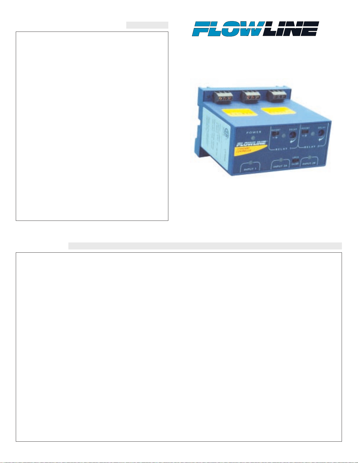
Remote Relay Controller
LC80 and LC82 Series
Owner’s Manual
Page 2
Step One
SPECIFICATIONS
Supply voltage: 120/240 VAC
@ 50-60 Hz.
Consumption: 5 watts max.
Sensor inputs: LC80: (1) four-wire flow switch
LC82: (2) four-wire flow switches
Sensor supply: 13.5 VDC @ 100 mA
Contact type: LC80: (1) SPDT relay
LC82: (2) SPDT relays
Contact rating: 250 VAC @ 10A
Contact latch: LC80: N/a
LC82: Select ON/OFF
Contact delay: 0-60 seconds
LED indication: Sensor, power and relay status
Electronics temp.: F: -40˚ to 158˚
C: -40˚ to 70˚
Enclosure type: 35 mm DIN rail
Encl. material: PP, UL94VO
Classification: General purpose
Certificate: CSA: LR 79326
CE compliance: EN 50082-2 immunity
EN 55011 emission
EN 61010-1 safety
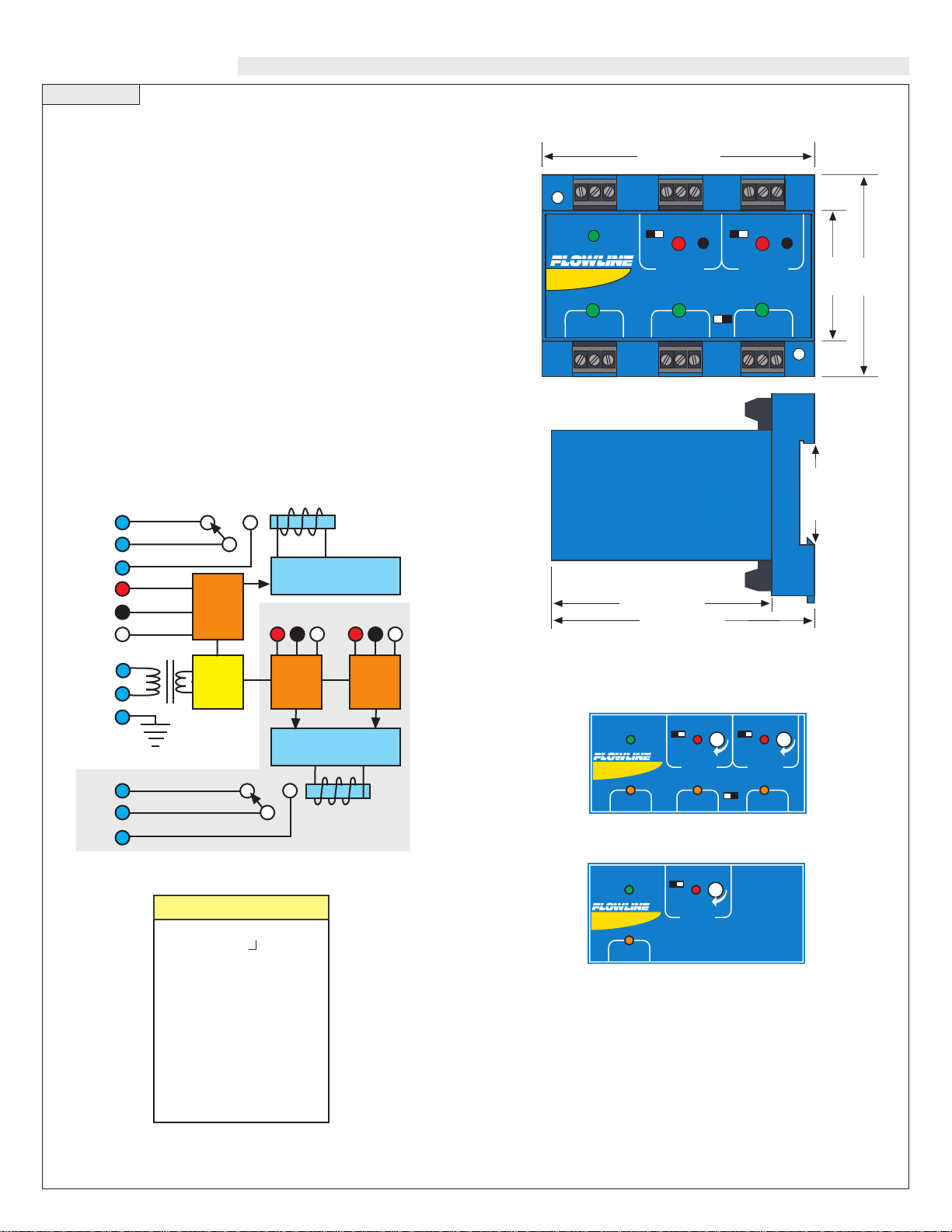
Dimensions:
LC82 Faceplate:
LC80 Faceplate:
+
INPUT 1 INPUT 2A INPUT 2B
P O W E R
IN VE R T
IN VE R T DE LA Y
+
DE LA Y
ON OFF
LATCH
STANDARD
CONTROLLER
“
-- --
RE L AY 1 RE L AY 2
+
+
+
INPUT 1
P O W E R
IN VE R T
DE LA Y
STANDARD
CONTROLLER
“
--
RE L AY 1
Power
Supply
Latch / Invert Logic
Time Delay
L1
L2
GND
Sensor
Input
2A*
Sensor
Input
2B*
(+) (-) (S)
Relay
("Relay 2" in LC82)
Relay
("Relay 1"
in LC82)
NC
C
NO
Sensor
Input
1
Latch / Invert Logic
Time Delay
NC
C
NO
(+)
(-)
(S)
(+) (-) (S)
LC8 _ - 1 0 0 1
Configuration
0 - (1) SPDT Relay
2 - (2) SPDT Relays
Remote Relay Controller
+
3.9" (98mm)
1.8"
(44mm)
2.7"
(68mm)
STANDARD
CONTROLLER
RELAY 1 RELAY 2
POWER
INPUT 1 INPUT 2A INPUT 2B
-
+
-
+
INVERT
DELAY
INVERT
DELAY
LATCH
ON OFF
3.1" (79mm)
35mm
DIN Rail
3.6" (92mm)
Page 3

Step Two Step Three
SAFETY PRECAUTIONS INTRODUCTION
About This Manual:
PLEASE READ THE ENTIRE MANUAL PRIOR TO
INSTALLING OR USING THIS PRODUCT. This manual
includes information on two different models of Remote Relay
Controllers for Flow applications from Flowline: LC80-1001 and
LC82-1001. Many aspects of installation and use are similar
between the two models.
User’s Responsibility for Safety:
Flowline manufactures several models of controller, with different
mounting and switching configurations. It is the user’s responsibility to select a controller model that is appropriate for the application, install it properly, perform tests of the installed system, and
maintain all components.
Electrical Shock Hazard:
It is possible to contact components on the controller that carry
high voltage, causing serious injury or death. All power to the controller and the relay circuit(s) it controls should be turned OFF prior
to working on the controller. If it is necessary to make adjustments
during powered operation, use extreme caution and use only insulated tools. Making adjustments to powered controllers is not recommended. Wiring should be preformed by qualified personnel in
accordance with all applicable national, state and local electrical
codes.
Flammable or Explosive Applications:
LC80 series remote mount controllers should not be used with
explosive or flammable liquids, which require an intrinsically
safe rating such as the Flowline LC90 series. If you are unsure of
the suitability of a controller for your installation, consult your
Flowline representative for further information.
Install In a Dry Location:
The controller housing is not designed to be immersed. It should
me mounted in such a way that it does not come into contact with
liquid. Its case is made out of PP (polypropylene). Refer to an
industry reference to ensure that compounds that may splash onto
the controller housing will not damage it. Such damage is not covered by the warranty.
Relay Contact Rating:
The relay is rated for a 10 amp resistive load. Many loads (such as
a motor during start-up or incandescent lights) are reactive and
have an inrush current characteristic that may be 10 to 20 times
their steady-state load rating. The use of a contact protection circuit
may be necessary for your installation if the 10 amp rating does not
provide an ample margin for such inrush currents.
Make a Fail-Safe System:
Design a fail-safe system that accommodates the possibility of relay
or power failure. If power is cut off to the controller, it will de-energize the relay. Make sure that the de-ener gized state of the relay is the
safe state in your process. For example, if controller power is lost, a
pump will turn off if it is connected to the Normally Open side of the
relay.
While the internal relay is reliable, over the course of time relay failure is possible in two modes: under a heavy load the contacts may be
“welded” or stuck into the energized position, or corrosion may build
up on a contact so that it will not complete the circuit when it should.
In critical applications, redundant backup systems and alarms must be
used in addition to the primary system. Such backup systems should
use different sensor technologies where possible.
While this manual offers some examples and suggestions to help
explain the operation of Flowline products, such examples are for
information only and are not intended as a complete guide to
installing any specific system.
Page 4

Step Four Step Five
GUIDE TO CONTROLS INSTALLATION
1. Power indicator:This green LED lights when AC power is ON.
2. Relay indicator: This red LED will light whenever the con-
troller energizes the relay, in response to the proper condition at
the switch input and after the time delay.
3. AC Power terminals: Connection of 120 VAC power to the
controller. The setting may be changed to 240 VAC if desired.
This requires changing internal jumpers; this is covered in the
Installation section of the manual. Polarity (neutral and hot) does
not matter.
4. Relay terminals (NC, C, NO): Connect the device you wish to
control (pump, alarm etc.) to these terminals: supply to the
Common (COM) terminal, and the device to the Normally Open
(NO) or Normally Closed (NC) terminal as required. The
switched device should be a noninductive load of not more than
10 amps; for reactive loads the current must be derated or protection circuits used. When the red LED is ON and the relay is in the
energized state, the NO terminal will be closed and the NC terminal will be open.
5. Time delay: Use potentiometer to set delay from 0.15 to 60 sec-
onds. Delay occurs during switch make and switch break.
6. Input indicators: Use these LEDs for indicating Flow or No-
Flow status of switch. For NC wiring, an Amber LED indicates
No-Flow and no LED indicates Flow. For NO wiring, an Amber
LED indicates Flow and no LED indicates No-Flow.
7. Invert switch:This switch reverses the logic of the relay control
in response to the switch: conditions that used to energize the
relay will now de-energize the relay and vice versa.
8. Latch switch (LC82): This switch determines how the relay
will be energized in response to the two sensor inputs. When
LATCH is OFF, the relay responds to switch Input 2Aonly; when
LATCH is ON, the relay will energize or de-energize only when
both switches (2Aand 2B) are in the same condition (Flow or NoFlow). The relay will remain latched until both switches change
conditions.
9. Input terminals: Connect the switch wires to these terminals:
Note the polarity: (+) is a 24 VDC, 50 mA power supply (connected to the red wire of a Flowline flow switch), and (-) is the
common ground path from the switch (connected to the black
wire). Also, the (S) is a 14 VDC, 25 mAsupply (connected to the
white wire). If polarity between the red and black wires is
reversed, the switch will change from NC to NO.
Panel DIN Rail Mounting:
The controller may be mounted by either a back panel using two
screws through mounting holes located at the corners of the controller
or by snapping the controller on 35 mm DIN Rail.
Note: Always install the controller in a location where it does not
come into contact with liquid.
Connecting N-channel Switches to Input Terminals:
Please note a difference between Flowline flow switches (N-channel,
P-channel and Relay). Use only the N-Channel or Relay switches
with the LC80 series of controller. Wire the Red wire to the (+) terminal and the Black wire to the (-) terminal. Wire the White wire to
the (S). See the illustration below to indicate wiring for your switch.
Reversing Red and Black wire will change switch from NC to NO.
Note: connect the Shield wire on the Flow switch to the GND terminal if required.
STANDARD
CONTROLLER
RE L A Y 1 R E L A Y 2
PO W E R
INPU T 1 INPU T 2A INPUT 2 B
-
+
-
+
INVERT
DELAY
INVERT
DELAY
LATCH
ON OFF
1
3
7
2
5
4 4
7
2
5
6
8
66
9
9 9
INPUT 1 INPUT 2A INP UT 2B
LATCH
ON OFF
White
Black
FT10-___2
GT10-___2
NC Wiring
Red
White
Red
FT10-___2
GT10-___2
NO Wiring
Black
INPUT
24 VDC
100 mA
Max
( - ) S
( + )
14 VDC
25 mA
Max
3.475"
2.2"
.275"
.225"
35 mm
DIN Rail
Page 5

Step Six Step Seven
INSTALLATION
VAC Power Input Wiring
Observe the POWER SUPPLY label on the LC80
series. The label identifies the power requirement
(120 or 240 VAC) and the terminal wiring. Note:
Polarity does not matter with the AC input terminal.
Relay Input Wiring
The relay is a single pole, double throw type rated
at 250 Volts AC, 10 Amps. The two terminal NO
and NC (normally open and normally closed) will
be used in different applications. Remember that
the "normal" state is when the relay coil is deenergized and the Red relay LED is Off / de-energized.
Changing from 120 to 240 VAC
1. Remove the back panel of the controller and gently slide the printed
circuit board from the housing. Use caution when removing the PCB.
2. Located jumpers JW1, JW2 and JW3 on the PCB.
3. To change to 240 VAC, remove jumpers from JW1 and JW2 and
place a single jumper across JW3. T o change to 120 VAC, remove
jumper JW3 and place jumpers across JW1 and JW2.
4. Gently return PCB into housing and replace back panel.
120 VAC
JWB
JWA
JWC
240 VAC
JWB
JWA
JWC
RE L AY 1
PO W ER
-
+
INV ERT
DEL AY
Ground
Neutral
Hot
RE L AY 1
PO W ER
-
+
INV ERT
DEL AY
Ground
Neutral
Hot
POWER
120 VAC, 50 - 60 Hz
L1
240 VAC, 50 - 60 Hz
L2
( )
NO NC
RELAY OUTPUT
250 VAC, 10 A
C
INSTALLATION
LED Indication:
Use LED's located above the input terminals to indicate whether the
switch is in a Flow or No-Flow state. With the flow switch wired NC,
the Amber LED indicates No-Flow and no LED indicates flow.
Wiring the switch NO (reversing the Red and Black wires), the Amber
LED indicates Flow and no LED indicates No-Flow.
NC Wiring NC Wiring NO Wiring NO Wiring
Amber OFF Amber OFF
INPUT 1
Black
Red
White
Green
INPUT 1
Black
Red
White
Green
INPUT 1
Red
Black
White
Green
INPUT 1
Red
Black
White
Green
Connecting Relay Switches to Input Terminals:
Please note a difference between Flowline flow switches (N-channel,
P-channel and Relay). Use only the N-Channel or Relay switches
with the LC80 series of controller. Wire the Red wire to the (+) terminal and the Black wire to the (-) terminal. Wire the White wire to
the (S). Jumper the Green wire to the (-) terminal. See the illustration below to indicate wiring for your switch. Reversing Red and
Black wire will change switch from NO to NC. Note: connect the
Shield wire on the Flow switch to the GND terminal if required.
INPUT 1 INPUT 2A INP UT 2B
LATCH
ON OFF
FT10-___5
GT10-___5
NO Wiring
Black
Red
Green
White
FT10-___5
GT10-___5
NC Wiring
Red
Black
Green
White
INPUT
24 VDC
100 mA
Max
( - ) S
( + )
14 VDC
25 mA
Max
Page 6

Step Eight Step Nine
TROUBLESHOOTING
Controller Logic: For all controllers, please use the following guide
to understand the operation of the Flowline LC80/LC82 controllers.
1. Make sure the Green power LED is On when power is supplied to
the controller.
2. For NC switch wiring, the input LED's on the controllers will be
Amber when the switch reads no-flow and Off when the switch
reads flow.
3. The input LED will always respond to its corresponding relay
LED. With invert Off (-), the relay LED will be On when the input
LED is On and Off when the input LED is Off. W ith invert On (+),
the relay LED will be Off when the input LED is On and On when
the input LED is Off.
4. The relay may be wired either NO or NC. The normal state of the
relay is when its LED is Off. With the LED On, the relay is in the
energized mode and all terminal connections are reversed.
5. LC82 model only, Latch ON operation: When both input LED's
are ON, the relay will be energized (red LED On). After that, if
one switch input turns Off, the relay will remain energized. Only
when both switch LED's are Off will the controller de-energize
the relay. The relay will not energize again until both switch
LED's are ON. Reversing Invert switch will reverse logic. See the
Logic Chart below for further explanation.
Set Points: If the preset factory calibration is not adequate for
your application, follow the calibration steps listed below. Note: the
switch's internal LED will be on when the switch detects no-flow and
will off when the switch detects flow.
1. Install the fitting and flow switch as described in the Installation
section of this manual. Turn the flow switch and controller power
on and adjust the flow rate to the application setting. If the medium to be sensed is likely to be subject to high temperature variations, the flow switch should be set at the highest normal temperature likely to be encountered.
2. Locate the potentiometer knob at the top of the flow switch. The
red LED is visible through the potentiometer. (If the LED is on,
slowly adjust the potentiometer counterclockwise, with a small
flat head screwdriver until the LED turns off.) The adjustment is
a single turn 270° potentiometer. The initial response time of the
flow switch after adjustment is 1 to 10 seconds. Adjust the potentiometer in slow increments and wait for the response.
If the LED is off, slowly adjust the potentiometer clockwise until
the light turns on. Then turn the potentiometer counterclockwise
to bring the LED off at a reliable setting. Remember, adjust the
potentiometer in slow increments and wait for the response.
3. Verify that the new calibration is correct by lowering the system
flow rate below the set point and check to see that the red LED
turns on. Then increase the flow rate above the set point and verify that the red LED turns off accordingly.
Liquid Switch Gas Switch
FT10-___5 Series GT10-___5 Series
EXAMPLES
Low Flow Alarm: The goal is to indicate when the flow rate falls
below a certain point. If it does, an alarm is supposed to sound, alerting the operator of a low flow condition.
If power is accidentally cut to the controller, the sensor's ability to
notify the operator of a low flow condition could be lost. The system
must alert the operator not only to low flow, but to controller power
loss. To do this, connect the hot lead of the alarm to the NC side of
the relay terminal of the controller. If power is lost, the relay will be
de-energized, and the alarm will sound (if there is still power to the
alarm circuit itself). The alarm circuit should have a non-interruptible
power supply or some other indicator or backup alarm to warn of a
power failure in the alarm circuit.
In this application, the normal status
is when the sensor is in the flow condition, and the relay will be energized
holding the alarm circuit open. If the
switch is wired NC, the input LED
will be off and the relay LED will
be on. So for this application,
Invert should be set to the On position. If the switch is wired NO, the
input LED and the relay LED will
be on simultaneously . So for this application, Invert should be set to the Off (-) position.
RE L AY 1 R EL A Y 2
PO W ER
-
+
-
+
INV ERT
DEL AY
INV ERT
DEL AY
Invert ON (+) setting
1 fps
90 fps
10 fps
.04 fps
3 fps
0.2 fps
 Loading...