

Page 1
Warranty, Service & Repair
WARRANTY
Flowline warrants to the original purchaser of its products that such
products will be free from defects in material and workmanship under
normal use and service for a period which is equal to the shorter of
one year from the date of purchase of such products or two years from
the date of manufacture of such products.
This warranty covers only those components of the products which
are non-moving and not subject to normal wear. Moreover, products
which are modified or altered, and electrical cables which are cut to
length during installation are not covered by this warranty.
Flowline’s obligation under this warranty is solely and exclusively
limited to the repair or replacement, at Flowline’s option, of the products (or components thereof) which Flowline’s examination proves to
its satisfaction to be defective. FLOWLINE SHALL HAVE NO
OBLIGATION FOR CONSEQUENTIAL DAMAGES TO PERSONAL OR REAL PROPERTY, OR FOR INJURY TO ANYPERSON.
This warranty does not apply to products which have been subject to
electrical or chemical damage due to improper use, accident, negligence, abuse or misuse. Abuse shall be assumed when indicated by
electrical damage to relays, reed switches or other components. The
warranty does not apply to products which are damaged during shipment back to Flowline’s factory or designated service center or are
returned without the original casing on the products. Moreover, this
warranty becomes immediately null and void if anyone other than service personnel authorized by Flowline attempts to repair the defective
products.
Products which are thought to be defective must be shipped prepaid
and insured to Flowline’s factory or a designated service center (the
identity and address of which will be provided upon request) within
30 days of the discovery of the defect. Such defective products must
be accompanied by proof of the date of purchase.
Flowline further reserves the right to unilaterally wave this warranty
and to dispose of any product returned to Flowline where:
a. There is evidence of a potentially hazardous material present
with product.
b. The product has remained unclaimed at Flowline for longer than
30 days after dutifully requesting disposition of the product.
THERE ARE NO WARRANTIES WHICH EXTEND BEYOND
THE DESCRIPTION ON THE FACE OF THIS WARRANTY. This
warranty and the obligations and liabilities of Flowline under it are
exclusive and instead of, and the original purchaser hereby waives, all
other remedies, warranties, guarantees or liabilities, express or
implied. EXCLUDED FROM THIS WARRANTY IS THE
IMPLIED WARRANTY OF FITNESS OF THE PRODUCTS FOR A
PARTICULAR PURPOSE OR USE AND THE IMPLIED WARRANTY OF MERCHANT ABILITY OF THE PRODUCTS.
This warranty may not be extended, altered or varied except by a written instrument signed by a duly-authorized officer of Flowline, Inc.
To register your product with the manufacturer, fill out the enclosed
warranty card and return it immediately to:
Flowline Inc.
10500 Humbolt Street
Los Alamitos, CA90720.
If for some reason your product must be returned for factory service, contact Flowline Inc. to receive a Material Return
Authorization number (MRA) first, providing the following information:
1. Part Number, Serial Number
2. Name and telephone number of someone who can answer
technical questions related to the product and its application.
3. Return Shipping Address
4. Brief Description of the Symptom
5. Brief Description of the Application
Once you have received a Material Return Authorization number,
ship the product prepaid in its original packing to:
Flowline Factory Service
MRA _____
10500 Humbolt Street
Los Alamitos, CA 90720
To avoid delays in processing your repair, write the MRA on the
shipping label. Please include the information about the malfunction with your product. This information enables our service technicians to process your repair order as quickly as possible.
®
Version 1.2A
© 2000 FLOWLINE Inc.
All rights reserved.
Manual # LA900005 08/00
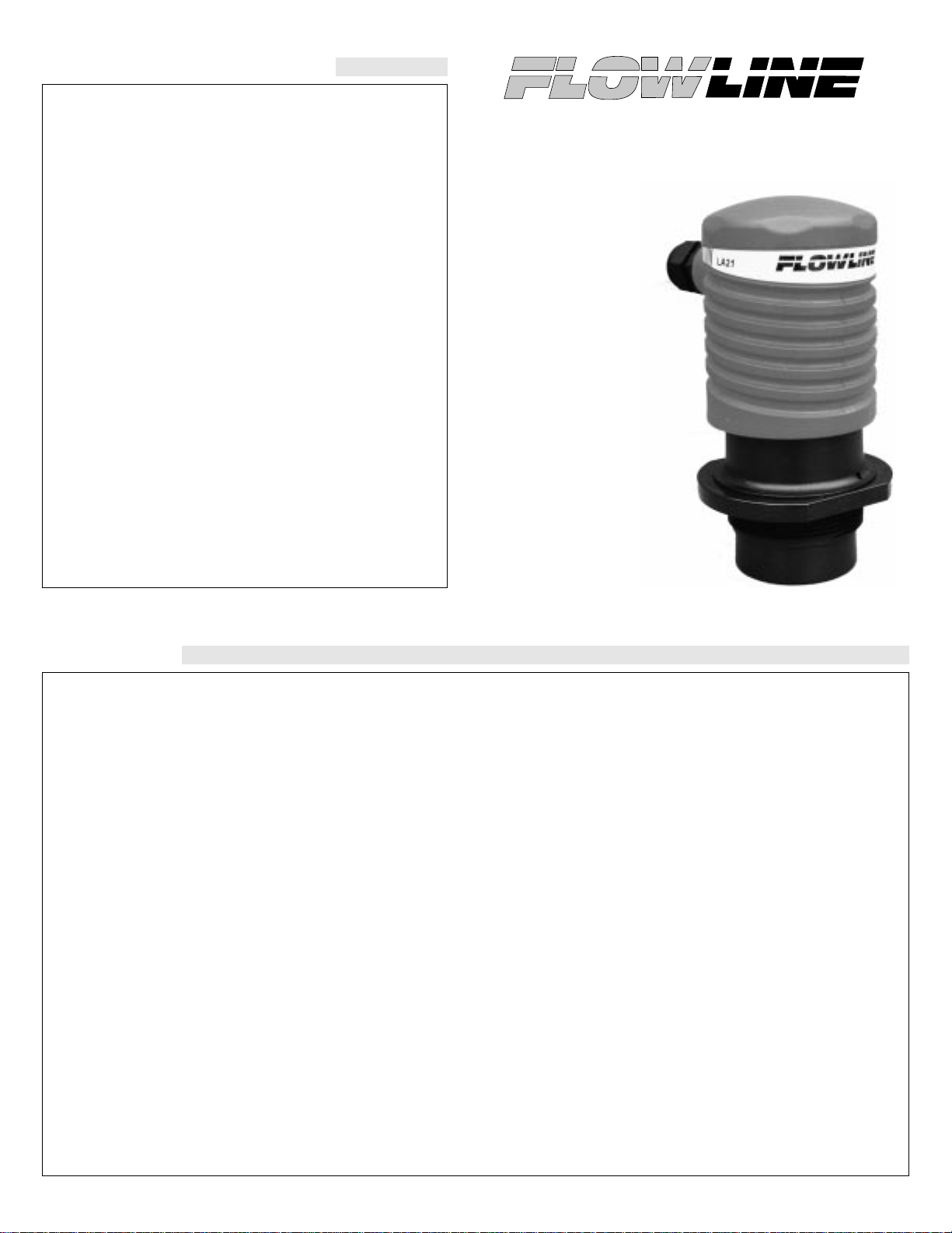
RicoRelay™
Bulk Tank Ultrasonic
Level Controller
Model LA21
Owner’s
Manual
Page 2
Step One
SPECIFICATIONS
Range: 6” to 12 feet (15.2 cm to 3.7 m)
Accuracy: ± 0.25% of span (air)
Resolution: 0.125” (3 mm)
Frequency: 50 kHz
Pulse rate: 3 per second
Beam width: 8° conical
Blocking distance: 6” (15.2 cm) minimum
LED Indication: Power, relay & fail-safety
Fail-safety: Power and echo fail-safe
Supply voltage: 5001: 120 VAC
5801: 18-30 VDC
Set points: 2 per relay
Adjustments: Potentiometer
Relay types: (2) Latched, SPDT
Relay rating: 5001: 250 VAC, 10A, 1/2 hp.
5801: 250 VAC, 10A, 1/4 hp.
Relay mode: Selectable NO or NC
Relay latch: ON or OFF
Hysteresis: Adjustable over range
Temperature rating: F: -40° to 140°
C: -40° to 60°
Temp. compensation: Automatic over entire range
Pressure rating: 30 psi (2 bar) @ 25 (C., derated @ 1.667 psi
(.113 bar) per (C. above 25 (C.
Enclosure rating: NEMA 4X (IP65)
Enclosure material: Polypropylene, U.L. 94VO
Transducer material: PVDF
Mounting conn.: 2” NPT (2” G)
Mounting gasket: Viton (2” G) metric only
Conduit connection: 1/2” NPT
CE compliance: EN 50082-2 immunity
(pending) EN 55011 emission
EN 61010-1 safety
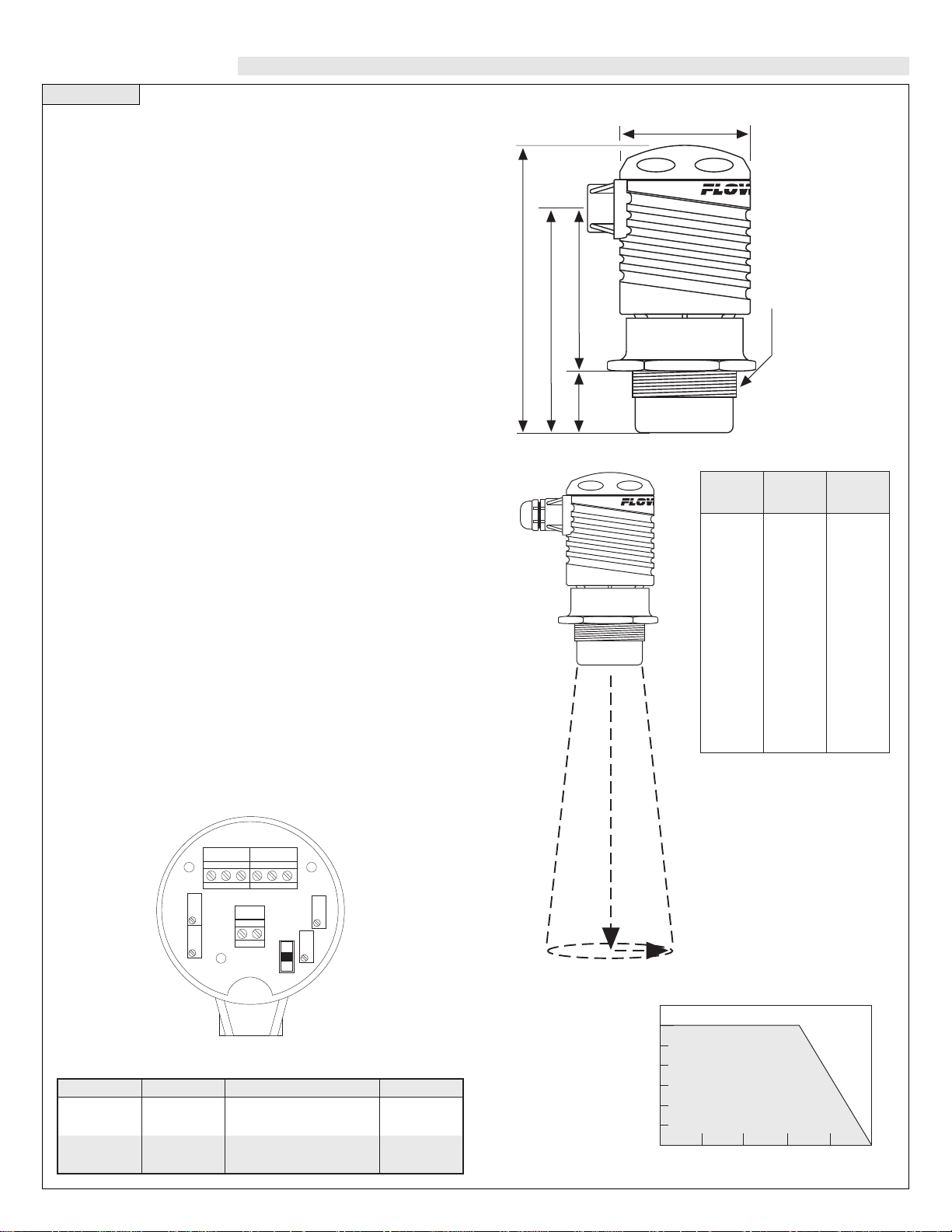
About Ultrasonic Technology:
An ultrasonic sound wave is pulsed three times per second from the
base of the transducer. The sound wave reflects against the process
medium below and returns to the transducer. The microprocessor
based electronics measures the time of flight between the sound generation and receipt, and translates this figure into the distance between
the transmitter and process medium below.
Beam Cone Radius:
RicoRelay Model Chart:
Temperature/Pressure Derating Chart:
RicoRelay Faceplate:
Dimensions:
6.3" (159 mm)
3.6 (92 mm)
4.9" (124 mm)
2.8" (71 mm)
1.3"
(32 mm)
2" NPT (2" G)
R
D
Tem erature/Pressure Derating
35
30
25
20
15
10
05
00
-40 -20 00 20 40 60
Operating Pressure (psi)
Temperature (°C)
Unacceptable
Range
Acceptable
Range
Model
LA21-5001
LA21-5801
LA21-5061
LA21-5861
Power
120 VAC
18-30 VDC
120 VAC
18-30 VDC
Mounting
2” NPT
2” NPT
2” G
2” G
Relay
250 VAC, 10A, 1/2 Hp.
250 VAC, 10A, 1/4 Hp.
250 VAC, 10A, 1/2 Hp.
250 VAC, 10A, 1/4 Hp.
NC C NO NC C NO
ON ON
LO
HI
LO
HI
RELAY 1
RELAY 2
L1 L2
AC
POWER
LO
HI
OP
Radius
Inches
Range
Feet
Radius
cm
1
2
3
4
5
6
7
8
9
10
11
12
1.2
2.1
2.9
3.7
4.9
5.4
6.2
7.1
7.9
8.8
9.6
10.4
3.1
5.2
7.3
9.5
11.6
13.7
15.9
18.0
20.1
22.3
24.4
26.5
Page 3

Step Two Step Three
SAFETY PRECAUTIONS GUIDE TO CONTROLS
About this Manual:
PLEASE READ THE ENTIRE MANUAL PRIOR TO
INSTALLING OR USING THIS PRODUCT. This manual
includes information on the RicoRelay™ bulk tank Ultrasonic
relay controller from FLOWLINE: LA21-5_01 and LA21-5_61.
Please refer to the part number located on the sensor label to verify the exact model which you have purchased.
User’s Responsibility for Safety:
FLOWLINE manufactures a wide range of liquid level sensors and
technologies. While each of these sensors is designed to operate in
a wide variety of applications, it is the user’s responsibility to select
a sensor model that is appropriate for the application, install it
properly, perform tests of the installed system, and maintain all
components. The failure to do so could result in property damage
or serious injury.
Proper Installation and Handling:
Because this is an electrically operated device, only properlytrained staff should install and/or repair this product. Use a proper
sealant with all installations. Note: Always install the 2” Viton gasket with the LA21-5_61. The G threaded version of the
RicoRelay™ will not seal unless the gasket is installed properly.
Never overtighten the transmitter within the fitting. Always check
for leaks prior to system start-up.
Wiring and Electrical:
A supply voltage of 120 VAC is used to power the LA21-50_1 controller. The sensor systems should never exceed a maximum of 120
volts AC. The supply voltage used to power the LA21-58_1 series
controller should never exceed a maximum of 30 volts DC.
Electrical wiring of the sensor should be performed in accordance
with all applicable national, state, and local codes.
Material Compatibility:
The RicoRelay™ enclosure is made of Polypropylene (PP). The
transducer is made of Polyvinylidene Fluoride (PVDF). Make sure
that the model which you have selected is chemically compatible
with the application liquids it will contact.
Enclosure:
While the transmitter housing is liquid-resistant when installed
properly, it is not designed to be immersed. It should be mounted
in such a way that the enclosure and diaphragm do not come into
contact with fluid.
Make a Fail-Safe System:
Design a fail-safe system that accommodates the possibility of
transmitter or power failure. In critical applications, FLOWLINE
recommends the use of redundant backup systems and alarms in
addition to the primary system.
Flammable, Explosive and Hazardous Applications:
The LA21 controller systems should not be used within flammable
or explosive applications.
1. Power indicator: This green LED lights when AC power is ON.
LED will also flash when a lost echo condition occurs.
2. Relay indicators: These red LED’s will light whenever the trans-
mitter energizes the relay , in response to the proper condition with
the set points.
3. AC Power terminals (LA21-50_1 series only): Connection of
120 VAC power to the controller. Polarity (neutral and hot) does
not matter.
3. DC Power terminals (LA21-58_1 series only): Connection of
18 to 30 VDC power to the controller. Please observe the Polarity
(positive and negative) of the terminal.
4. Relay terminals (NC, C, NO): Connect the device you wish to
control (pump, valve, alarm etc.) to these terminals: supply to the
COM terminal, and the device to the NO or NC terminal as
required. The switched device should be a noninductive load of
not more than 10 amps; for reactive loads the current must be derated or protection circuits used. When the red LED is ON and the
relay is in the energized state, the NO terminal will be closed and
the NC terminal will be open.
5. Relay Potentiometers: Adjusts the switching positions for each
relay with its own independent Hi and Lo adjustment.
6. Selector Switch: Allows for independent adjustment of the Hi or
Lo setting.
Warning
Always install the 2" V iton gasket with all versions of the LA215_61. The G threaded version of the RicoRelay will not seal
unless the gasket is installed properly.
NC C NO NC C NO
ON ON
LO
HI
LO
HI
RELAY 1
RELAY 2
L1 L2
AC
POWER
LO
HI
OP
1
3
4
2
5
6
24
5
5
5
Page 4

Step Four Step Five
WIRING INSTALLATION
FLOWLINE’s LA21 controller may be installed through the top wall
of a tank. Installation requires a 2" NPT (G) fitting or blind flange.
1. Install the appropriate 2" fitting in the top wall of the tank. Prior
to installation, make sure that the fitting has been installed properly and checked for leaks. Use a proper sealant at the time of
installation to ensure a liquid-tight seal. Secondly, make sure that
the fittings threads are not damaged or worn.
2. Insert the controller into the fitting and tighten to hand tight.
3. Always check for leaks prior to system start-up. To ensure proper installation, a complete leak test and simulation of actual
process conditions should be preformed.
Fitting Installation Flange Installation
Observe the Flange Chart
to the left to determine
the maximum depth for a
flange installation.
Warning
Do not install the LA21 in pressurized applications above 30 psi.
Always install the 2" V iton gasket with all versions of the LA21-
5_61. The G threaded version of the LA21-5_61 will not seal
unless the gasket is installed properly and checked for leaks.
Use a proper sealant at the time of installation to ensure a liquidtight seal. Secondly, make sure that the fittings threads are not
damaged or worn.
A supply voltage of 120 VAC is used to power the LA21 controller.
Electrical wiring of the sensor should be performed in accordance
with all applicable national, state, and local codes.
Wiring AC Power to LA21 (models LA21-50_1):
Polarity does not matter for the LA21-50_1. Do not exceed the 120
VAC power rating. The 2 relays can be connected to pumps, valves,
alarms, PLC’s, etc. as long as they do not exceed the 10A, 250 VAC,
1/2 Hp rating. Below illustrates using the same 120 VAC power suppling the LA21-50_1 to control two independent pumps directly.
Wiring DC Power to LA21 (models LA21-58_1):
Please observe polarity for the LA21-58_1. The 2 relays can be connected to pumps, valves, alarms, PLC’s, etc. as long as they do not
exceed the 10A, 250 VAC, 1/4 Hp rating. Below illustrates using the
same VDC power suppling the LA21-58_1 to control a high level and
low level alarm directly.
Wiring to the Relays:
The 2 relays are isolated from the power required to operate the
LA21. The relays can be used to control a device on a separate power
system. The illustration below demonstrates the LA21-50_1 controlling two alarms powered from a different power supply. All relay ratings will still apply.
NC C NO NC C NO
ON ON
LO
HI
LO
HI
RELAY 1
RELAY 2
L1 L2
AC
POWER
LO
HI
OP
HOT NEUTRAL
Flange
Inner Diameter
Inch (cm)
3 (7.6)
4 (10.2)
5 (12.7)
6 (15.2)
7 (17.8)
8 (20.3)
Flange
Depth
Inch (cm)
3 (7.6)
7 (17.8)
11 (27.9)
15 (38.1)
19 (48.3)
26 (66.0)
Depth
Inner Diameter
VACUUM
Do not install
LA21 at an
angle
Avoid
interference from
side of tank
Avoid
interference from
obstructions in
tank
LA21 will not
operate in
vacuum
NC C NO NC C NO
ON ON
LO
HI
LO
HI
RELAY 1
RELAY 2
+ -
AC
POWER
LO
HI
OP
Positive Negative
NC C NO NC C NO
ON ON
LO
HI
LO
HI
RELAY 1
RELAY 2
L1 L2
AC
POWER
LO
HI
OP
HOT NEUTRAL
POSITIVE NEGATIVE
18-30 VDC
18-30 VDC
120 VAC
120 VAC
Flange Chart
Page 5

Step Six Step Seven
CALIBRATION CALIBRATION
Power LED Indication
The LA21 features a single Green LED which indicates power and
fail-safe conditions. During normal operation, the LED will be ON
continuously to indicate that the controller has power and a strong
echo signal return strength.
Should the LED begin to FLASH, this indicates that the LA21 has
lost the acoustic signal and has gone into a fail-safe condition. During
the lost echo condition, both relays will energize indicating a full tank
condition. Once re-acquired, the LED will turn back ON continuously and the relays will return to their proper state. Note: during a failsafe condition, both relays will energize. Design your system such
that an energized relay state is a fail-safe condition.
Relay LED Indication
The LA21 features dual Red LED’s which indicate relay status.
When the LED is On, the corresponding relay is energized. When the
LED is Off, the corresponding relay is de-energized.
NC C NO NC C NO
ON ON
LO
HI
LO
HI
RELAY 1
RELAY 2
L1 L2
AC
POWER
LO
HI
OP
Relay 2
Red LED
Relay 1
Red LED
Power
Green
LED
Hi Set
Point
Lo Set
Point
Relay Energized
Relay De-energized
No Change To Relay
Relay LED Indication II
The relay’s in the LA21 will energize when the liquid level is above
both Hi and Lo points. The relay will de-energize when the level falls
below both the Hi and Lo points.
Low Level Alarm
The goal is to make sure that the liquid level does
not fall below a certain point. If it does, an alarm is
supposed to sound, alerting the operator of a low
level condition.
To do this, connect the alarm to the NC side of the
relay. Connect the source of power to the Com terminal of the relay.
In this application, the switch point is normally wet.
In this condition, the relay will be energized so the
alarm will not sound: i.e., the Red relay LED will be
On. If the fluid level falls below the low switch point,
the relay de-energizes, which closes the alarm circuit
and the alarm sounds.
High Level Alarm
In the same manor, this system
can be used to sound an alarm
when fluid reaches a high
level, with just a change in the
location of the switch point
and the reversing of the relay.
The alarm is now connected to
the NO side of the relay.
The sensor is normally dry. In
this condition, the relay will be
de-energized so the alarm does
not sound: i.e., the Red relay
LED should be Off. If the fluid
level rises to the high sensor
point, the sensor goes on, the relay energizes, and the alarm sounds.
Single Point Relay
Each relay can be used as a high or low level alarm. The instructions
below can be used for either function.
1. Turn on 120 VAC power supply.
2. Turn the Hi and Lo potentiometers for the
relay fully clockwise (about 18 turns).
3. Set the input level to its set point.
4. Flip selector switch to Hi.
5. Adjust Hi potentiometer counter-clockwise
until the LED for that relay just turns ON.
6. Turn Lo potentiometer for the relay fully
counter-clockwise (about 18 turns).
7. Flip selector switch to Lo.
8. Adjust Lo potentiometer clockwise until the
LED for that relay turns OFF.
9. Adjust Lo potentiometer counter-clockwise 1/4 turn, LED will
turn ON.
10. Repeat steps 3 to 9 for the other relay.
11. Flip selector switch to OP.
Note:to protect the loads, the relay set points should be adjusted
before the loads are connected.
Note:calibrate the LA21 to a static liquid level or stationary object.
Note: Low level alarm is wired NC and
the high level alarm is wired NO.
(LA21-50_1 Shown)
120 VAC
Warning
A supply voltage of 120 VAC is used to power the LA21-50_1
series controller. If making adjustments during powered operation,
use extreme caution and use only insulated tools. Also, calibrate
all models of the LA21 to a static liquid level or stationary object.
Wiring should be preformed by qualified personnel in accordance
with all applicable national, state and local electrical codes.
Note: If making adjustments during powered operation, go slow, use
extreme caution and use only insulated tools.
Note:A dry calibration is possible when using a solid target. Position
the LA21 in a secure location at the exact distances required.
High
Alarm
Low
Alarm
HOT NEUTRAL
ON ON
RELAY 1
NC C NO NC C NO
HI
LO
POWER
L1 L2
HI
OP
AC
LO
RELAY 2
HI
LO
High
Alarm
or
Low
Alarm
Page 6

Step Eight Step Nine
CALIBRATION
General:
The LA21 series controller itself requires no periodic maintenance
except cleaning as required. It is the responsibility of the user to determine the appropriate maintenance schedule, based on the specific
characteristics of the application liquids.
Cleaning Procedure:
1. Power: Make Sure that all power to the transmitter, controller
and/or power supply is completely disconnected.
2. Sensor Removal: In all through-wall installations, make sure
that the tank is drained well below the sensor prior to removal.
Carefully, remove the sensor from the installation.
3. Cleaning the Sensor: Use a soft bristle brush and mild detergent, carefully wash the transducer of the LA21. Do not use a
harsh abrasive such as steel wool or sandpaper, which might damage the surface of the transmitter. Do not use incompatible solvents which may damage the PVDF transducer or the transmitters
PP body.
4. Sensor Installation: Follow the appropriate steps of installation as outlined in the installation section of this manual.
Controller Logic
For all controllers, please use the following guide to understand the
operation of the LA21-5__1.
1. Power LED: Make sure the Green power LED is On when
power is supplied to the controller.
2. Relay LED(s): The relay(s) LED(s) on the LA21 will be energized when the level is above the Hi point and de-energized when
the level is below the Lo point. When the level is between the Hi
and Lo points, the relay will no change its state.
Relay Logic:
The relay can either be an independent relay (high or low level alarm)
or can be a latching relay (automatic fill or empty).
High Level Low Level Automatic
Alarm Alarm Control
Automatic Fill:
This system consists of a tank with a pump that is controlled by the
LA21. We connect the pump to the NC side of the relay. When the
relay is de-energized, the pump will turn On and fill the tank. When
the relay is energized, the pump will turn Off and stop filling the tank.
NOTE: If the pump motor load
exceeds the rating of the controller’s relay, a stepper relay of
higher capacity must be used as
part of the system design.
Automatic Empty:
Note that a similar system logic
can be used for an automatic
empty operation simply by controlling a pump that pumps
fluid out of the tank instead of
into it. However, note that the
pump will now be connected to
the NO side of the relay. When
the relay is energized, the pump will turn On and empty the tank.
When the relay is de-energized, the pump will turn Off and stop emptying the tank.
Latching Relay
1. Turn on 120 VAC power supply.
2. Turn the Hi and Lo potentiometers for the
relay fully counter-clockwise (about 18
turns).
3. Set the input level to its low set point.
4. Flip selector switch to Lo.
5. Adjust Lo potentiometer clockwise until the
LED for that relay just turns OFF.
6. Turn Hi potentiometer for the relay fully
clockwise (about 18 turns)
7. Flip selector switch to Hi.
8. Set input level to its highest point.
9. Adjust Hi potentiometer counter-clockwise until the LED for that
relay turns ON.
10. Repeat steps 3 to 9 for the other relay.
11. Flip selector switch to OP.
Note:to protect the loads, the relays should be adjusted before the
loads are connected.
Note:calibrate the LA21 to a static liquid level or stationary object.
MAINTENANCE
Note: Auto fill pumps are wired NC and
auto empty pumps are wired NO.
(LA21-50_1 Shown)
120 VAC
Note: If making adjustments during powered operation, go slow, use
extreme caution and use only insulated tools.
Note:Adry calibration is possible when using a solid target. Position
the LA21 in a secure location at the exact distances required.
HOT NEUTRAL
ON ON
RELAY 1
NC C NO NC C NO
HI
L1 L2
OP
AC
LO
POWER
RELAY 2
HI
HI
LO
LO
High
Level
Set Point
Low
Level
Set Point
Energized
Point
Hi Set
De-energized
Relay
Relay
Energized
Point
Lo Set
De-energized
Relay
Relay
Energized
Point
Hi Set
No Change
To Relay
Point
Lo Set
De-energized
Relay
Relay
 Loading...