

Page 1
Warranty, Service & Repair
WARRANTY
Flowline warrants to the original purchaser of its products that such
products will be free from defects in material and workmanship under
normal use and service for a period which is equal to the shorter of
one year from the date of purchase of such products or two years from
the date of manufacture of such products.
This warranty covers only those components of the products which
are non-moving and not subject to normal wear. Moreover, products
which are modified or altered, and electrical cables which are cut to
length during installation are not covered by this warranty.
Flowline’s obligation under this warranty is solely and exclusively
limited to the repair or replacement, at Flowline’s option, of the products (or components thereof) which Flowline’s examination proves to
its satisfaction to be defective. FLOWLINE SHALL HAVE NO
OBLIGATION FOR CONSEQUENTIAL DAMAGES TO PERSONAL OR REAL PROPERTY, OR FOR INJURY TO ANYPERSON.
This warranty does not apply to products which have been subject to
electrical or chemical damage due to improper use, accident, negligence, abuse or misuse. Abuse shall be assumed when indicated by
electrical damage to relays, reed switches or other components. The
warranty does not apply to products which are damaged during shipment back to Flowline’s factory or designated service center or are
returned without the original casing on the products. Moreover, this
warranty becomes immediately null and void if anyone other than service personnel authorized by Flowline attempts to repair the defective
products.
Products which are thought to be defective must be shipped prepaid
and insured to Flowline’s factory or a designated service center (the
identity and address of which will be provided upon request) within
30 days of the discovery of the defect. Such defective products must
be accompanied by proof of the date of purchase.
Flowline further reserves the right to unilaterally wave this warranty
and to dispose of any product returned to Flowline where:
a. There is evidence of a potentially hazardous material present
with product.
b. The product has remained unclaimed at Flowline for longer than
30 days after dutifully requesting disposition of the product.
THERE ARE NO WARRANTIES WHICH EXTEND BEYOND
THE DESCRIPTION ON THE FACE OF THIS WARRANTY. This
warranty and the obligations and liabilities of Flowline under it are
exclusive and instead of, and the original purchaser hereby waives, all
other remedies, warranties, guarantees or liabilities, express or
implied. EXCLUDED FROM THIS WARRANTY IS THE IMPLIED
WARRANTY OF FITNESS OF THE PRODUCTS FOR A PARTICULAR PURPOSE OR USE AND THE IMPLIED WARRANTY OF
MERCHANT ABILITY OF THE PRODUCTS.
This warranty may not be extended, altered or varied except by a written instrument signed by a duly-authorized officer of Flowline, Inc.
To register your product with the manufacturer, go to the Flowline
website for on-line registration. The website address is as follows:
www.flowline.com
On-line Warranty Registration can be found under Contact Us in
the Navigation Bar along the side of the home page.
If for some reason your product must be returned for factory service, contact Flowline Inc. at (562)598-3015 to receive a Material
Return Authorization number (MRA), providing the following
information:
1. Part Number, Serial Number
2. Name and telephone number of someone who can answer
technical questions related to the product and its application.
3. Return Shipping Address
4. Brief Description of the Symptom
5. Brief Description of the Application
Once you have received a Material Return Authorization number,
ship the product prepaid in its original packing to:
Flowline Factory Service
MRA _____
10500 Humbolt Street
Los Alamitos, CA 90720
To avoid delays in processing your repair, write the MRA on the
shipping label. Please include the information about the malfunction with your product. This information enables our service technicians to process your repair order as quickly as possible.
®
Version 0.1A
© 2005 FLOWLINE Inc.
All rights reserved.
Manual # LM900005 05/05
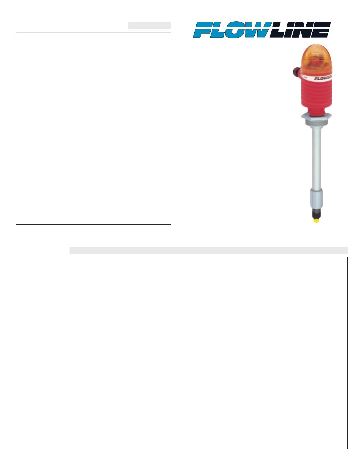
Switch Pak™
w/ Compact
Relay Controller
A _ 1 3 Series
Owner’s Manual
Page 2
Step One
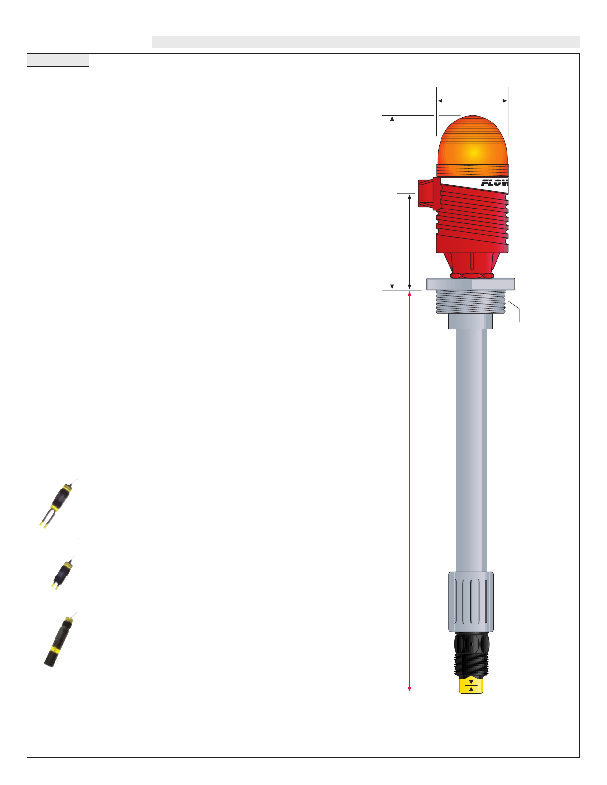
SPECIFICATIONS
3.5"(89mm)
6.5"(165mm)
2.8"
(71mm)
A (Specify)
2" NPT (1-1/2" G)
Specifications:
Length: 6" to 10' (15 cm to 3m)
Switch points: 1 (set by factory)
Orientation: ± 30˚ vertical
Supply voltage: 120/240 VAC @ 50-60 Hz.
Contact type: (1) SPDT relay
Contact rating: 250 VAC @ 10A
Contact delay: 0-60 seconds
LED indication: Power, relay and sensor status
Strobe type: _21_: Xenon tube
_22_: N/A
Strobe flash: _21_: 1 per second
_22_: N/A
Process temp.: F: -40˚ to 194˚
C: -40˚ to 90˚
Electronics temp.: F: -40˚ to 140˚
C: -40˚ to 60˚
Pressure: AU13: 150 psi (10 bar)
AZ13: 150 psi (10 bar)
AV13: 25 psi (1.7 bar)
Wetted material: 42__: PP
52__: PVDF Kynar®
Process mount: _2_3: 2" NPT
_2_7: 1 1/2” G
Enclosure rating: NEMA 4X (IP65)
Installed height: _21_: 6.5" (16.5 cm)
_22_: 4.9" (12.4 cm)
Encl. material: _21_: PP, UL94VO and polycarbonate
_22_: PP, UL94VO
Conduit entrance: Single, 1/2" NPT
Classification: General purpose
CE compliance: EN 50082-2 immunity
EN 55011 emission
EN 61010-1 safety
Sensor Technologies:
Vibration (LZ10 series)
Typically applied in wastewater media with light coating and/or foaming characteristics
Ultrasonic (LU10 series)
Broadly applied in chemical, solvent, hydrocarbon and
light weight oil media
Buoyancy (LV10 series)
Best applied in clean water or water-like chemical
media that is non-coating or scaling
Page 3

Step Two
COMPONENTS
Ultrasonic
AU13-4213
1 x LU10-1305
1 x LM45-1001
1 x LC10-1002
AU13-4217
1 x LU10-1325
1 x LM45-1061
1 x LC10-1052
AU13-5213
1 x LU10-2305
1 x LM45-5001
1 x LC10-1002
AU13-5217
1 x LU10-2325
1 x LM45-5061
1 x LC10-1052
Buoyancy
AV13-4213
1 x LV10-1301
1 x LM45-1001
1 x LC10-1002
AV13-4217
1 x LV10-1351
1 x LM45-1061
1 x LC10-1052
AV13-5213
1 x LV10-5301
1 x LM45-5001
1 x LC10-1002
AV13-5217
1 x LV10-5351
1 x LM45-5061
1 x LC10-1052
Vibration
AZ13-4213
1 x LZ12-1405
1 x LM45-1001
1 x LC10-1002
AZ13-4217
1 x LZ12-1425
1 x LM45-1061
1 x LC10-1052
Component List:
A (Specify)
Switch Pak Fitting
P/N: LM45-1001, LM45-1061,
LM45-5001 or LM45-5061
Compact Relay Controller
P/N: LC10-1001, LC10-1051,
LC10-1002 or LC10-1052
Switch-Tek Level Switch
P/N: LU10-1305. LU10-1325,
LU10-2305, LU10-2325
LV10-1301, LV10-1351,
LV10-5301, LV10-5351,
or LZ12-1405
Ultrasonic
AU13-4223
1 x LU10-1305
1 x LM45-1001
1 x LC10-1001
AU13-4227
1 x LU10-1325
1 x LM45-1061
1 x LC10-1051
AU13-5223
1 x LU10-2305
1 x LM45-5001
1 x LC10-1001
AU13-5227
1 x LU10-2325
1 x LM45-5061
1 x LC10-1051
Buoyancy
A
V13-4223
1 x LV10-1301
1 x LM45-1001
1 x LC10-1001
A
V13-4227
1 x LV10-1351
1 x LM45-1061
1 x LC10-1051
AV13-5223
1 x LV10-5301
1 x LM45-5001
1 x LC10-1001
AV13-5227
1 x LV10-5351
1 x LM45-5061
1 x LC10-1051
Vibration
AZ13-4223
1 x LZ12-1405
1 x LM45-1001
1 x LC10-1001
AZ13-4227
1 x LZ12-1425
1 x LM45-1061
1 x LC10-1051
Strobe Alert Configuration:
(AU23-432_, A V23-432_ or AZ23-432_)
Standard Configuration:
(AU13-_22_, A V13-_21_ or AZ13-_21_)
3/4" NPT
(3/4" G)
2" NPT
(1-1/2" G)
Pipe
Socket
Pipe
Coupling
w/ 3/4"
Thread
Switch Pak Fitting includes
the following parts:
1 Fitting
1 Coupling
1 Customer specified pipe
A (Specify)
Page 4

Step Four
ASSEMBLY OF SWITCH PAK™
Step Three
SAFETY PRECAUTIONS
About this Manual: PLEASE READ THE ENTIRE MANU-
AL PRIOR TO INSTALLING OR USING THIS PRODUCT. This
manual includes information on the Switch Pak™ with Compact
Relay Controller: AU13-_2__, AZ13-_2__ and AV13-_2__. The
units are identical except for the material of construction, choice of
Strobe Alert and the sensors technology.
User's Responsibility for Safety: Flowline manufactures
a wide range of liquid level sensors, controllers, and mounting systems. It is the user's responsibility to select components that are
appropriate for the application, install them properly, perform tests
of the installed system, and maintain all components. The failure to
do so could result in property damage or serious injury.
Proper Installation and Handling: Use a proper sealant
with all installations. Never overtighten the components. Always
check for leaks prior to system start-up.
Material Compatibility:
Polypropylene (PP, a polyolefin): Sensor, Switch Pak™ fitting,
Controller Housing.
Polyvinylidene Fluoride (PVDF): Sensor and SWitch Pak™ fitting.
Viton (a fluorocarbon): O-ring.
Make sure that the application liquids are compatible with the
materials that will be wetted. To determine the chemical compatibility between the components and its application liquids, refer to
the Compass Corrosion Guide, available from Compass
Publications (phone 858-589-9636).
Temperature and Pressure: Switch Pak™ is designed for
use in application temperatures up to 90° C (194° F). The V ibration
and Ultrasonic packages are designed for pressurized applications
up to 150 psi (10 bar) and the Buoyancy package is designed for
use up to 25 psi (1.7 bar).
Wiring and Electrical: Electrical wiring of any liquid level
control system should be performed in accordance with all applicable national, state, and local codes. Take care not to cut or break
the outer insulation jacket of wiring that may be immersed while
routing cables in the Switch Pak™ system. Such breaks of the liquid seal of the sensor system may lead to component failure.
Flammable, Explosive and Hazardous Applications:
The AU13-_2__, AV13-_2__ and AZ13-_2__ Switch Pak™
should not be used within classified hazardous environments.
Make a Fail-Safe System: Design a fail-safe system that
accommodates the possibility of system or power failure. In critical applications, Flowline recommends the use of redundant backup systems and alarms in addition to the primary system.
About Switch Pak™: Flowline’s Switch Pak™ with Compact
Relay Controller Assembly is an single-point mounting system for
installing one level sensor vertically within a tank. The compact relay
controller features a 120/240 VAC controller with a 250 VAC, 10A
SPDT relay contract. Switch Pak™ mounts vertically through a standard 2" NPT (1 1/2” G) tank adapter, or on a side mount bracket (such
as the LM50-1001).
Relay Controller: The level switch is
pre-wired before shipment to the 2-pole terminal strip [Input 1 (+) & (-)]. The switch
technologies used to indicate level are either
Ultrasonic, Buoyancy or Vibration. The
Compact Relay Controller provides a 1/2”
Conduit connection and 6 poles for wire termination of power and relay contact. Use the
AC, AC and GND terminals for providing
power. Use the NC, NC and COM terminals
for interfacing to the relay contact.
Vibration (LZ12-1405)
Wire Configuration:
RELAY
Red
Black
White
Green
Orange
(+)
(-)
N/A
N/A
N/A
Shld
RELAY
(+)
(-)
N/A
N/A
Shld
Red
Black
White
Green
REED
N/A
(-)
(+)
Shld
Red
Black
White
Ultrasonic (LU10-_305 or LU10-_325) Wire
Configuration:
Buoyancy (LV10-_301 or LV10-_351) Wire
Configuration:
Compact
Relay Controller
(inside shown)
Page 5

Step Five
INSTALLATION
Switch Pak™, In-Tank Installation:
Flowline's Switch Pak™ mounting system is an in-tank fitting, which
enables users to install any technology, along the entire length of
track. Switch Pak™ may be installed thru the top wall of any tank or
flange, using a standard 2" NPT tank adapter or blind flange. If tank
top is not available, Flowline's side mount bracket, LM50-1001,
enables Switch Pak™ to be installed directly to the side wall or lip of
the tank.
T ank Adapter:
Flange Mounting:
Side Mount Bracket:
Lip of Tank Side-Wall
Step Six
GUIDE TO CONTROLS
1
3
6
4
2
5
8
7
1. Power indicator:This green LED lights when AC power is ON.
2. Relay indicator: This red LED will light whenever the con-
troller energizes the relay, in response to the proper condition at
the sensor inputs and after the time delay.
3. AC Power terminals: Connection of 120 VAC power to the
controller. The setting may be changed to 240 VAC if desired.
This requires changing internal jumpers; this is covered in the
Installation section of the LC10/11 Series Manual. Polarity (neutral and hot) does not matter.
4. Relay terminals (NC, C, NO): Connect the device you wish to
control (pump, alarm etc.) to these terminals: supply to the COM
terminal, and the device to the NO or NC terminal as required.
The switched device should be a noninductive load of not more
than 10 amps; for reactive loads the current must be derated or
protection circuits used. When the red LED is ON and the relay
is in the energized state, the NO terminal will be closed and the
NC terminal will be open.
5. Invert switch: This DIP switch reverses the logic of the relay
control in response to the sensor(s): conditions that used to energize the relay will make it turn off and vice versa.
6. Time Delay: After the input(s) change(s) state, this control sets
a delay from 0.15 to 60 seconds before the relay will respond.
7. Input 1A indicator: These amber LED will light immediately
whenever the appropriate sensor attached to the terminals detects
liquid, and will turn off when it is dry.
8. Input terminals: Connect the wiring from the sensors to these
terminals. Note the polarity: (+) is a 13.5 VDC, 27 mA power
supply, and (-) is the return path from the sensor. If polarity is
reversed, the sensors will not work.
Input 1A
AC
PP
RR
115 VAC
220 VAC
AC
GND
NC
C
NO
DELAY
INVERINVERT +/- +/-
(+)
(-)
Page 6

Step Seven
VAC Power Input Wiring: Observe the labeling on the con-
troller. Note: Polarity does not matter with the AC input terminal.
Relay Input Wiring: The relay is a single pole, double throw
type rated at 250 Volts AC, 10 Amps. The terminals Normally Open
(NO) and Normally Closed (NC) will be used in different applications. Remember that the "normal" state is when the relay coil is deenergized and the Red relay LED is OFF (de-energized).
A typical application for the Switch Pak™ with Compact Relay
Controller is to operate a pump or valve between the two set points
(automatic fill or empty). In this application, a pump or valve can be
wired to either the Normally Open (NO) or Normally Closed (NC)
side of the relay.
D
Relay
Terminals
Strobe Alert Output
With the Strobe Alert wired NO, the strobe will flash when the Red
LED is ON (Invert OFF). The strobe will flash when the Red LED is
OFF when wired NC or by turning the Invert ON. If the strobe is
wired NC and the Invert is ON, the strobe will flash when the Red
LED is ON (same as NO wiring and Invert OFF).
NO Wiring NC Wiring
Power to
Switch Pak
not shown.
Power to
Switch Pak
not shown.
Power to
Switch Pak
not shown.
WIRING
Step Eight
MAINTENANCE
General: The Switch Pak™ with Compact Relay Controller
requires no periodic maintenance except cleaning as required. It is the
responsibility of the user to determine the appropriate maintenance
schedule, based on the specific characteristics of the application liquids.
Cleaning Procedure:
1. Power: Make Sure that all power to the sensor, controller and/or
power supply is completely disconnected.
2. Sensor Removal: Make sure that the tank is in a state where it
is safe to remove the sensors. Carefully, remove the Switch Pak™
from the installation.
3. Cleaning the Sensor: Use a soft bristle brush and mild deter-
gent, carefully wash the Switch Pak™. Do not use harsh abrasives such as steel wool or sandpaper, which might damage the
surface sensor. Do not use incompatible solvents which may
damage the sensor's PP or Ryton plastic body.
4. Sensor Installation: Follow the appropriate steps of installa-
tion as outlined in the installation section of this manual.
Controller Logic:
1. Power LED: Make sure the Green power LED is On when
power is supplied to the controller.
2. Input LED(s): The input LED on the controller will be Amber
when the switch is wet and Off when the switch is dry. Note: see
Step 5 regarding reed switches. If the LED's are not switching the
input LED, test the level switch.
3. Relays: When both inputs are wet (Amber LED's On), the relay
will be energized (Red LED On). After that, if one switch
becomes dry, the relay will remain energized. Only when both
switches are dry (both amber LED's Off) will the controller deenergize the relay. The relay will not energize again until both
switches are wet. See the Relay Latch Logic Chart below for further explanation.
Current Test (Ultrasonic and Vibration only):
Used to verify if the sensor is indicating a wet or dry condition. This
test uses only two wires (Red and Black). The sensor draws 5 mA
(ultrasonic) or 8 mA (vibration) when it is dry, and 19 mA when wet.
The White and Green wires are not used.
Contact Test (Buoyancy only):
Used to verify if the reed switch is switching between dry (open) and
wet (closed). Check for continuity across Black and White (open for
dry and closed for wet). Checking across Black and Red will result
in a closed when dry and open when wet condition.
Red
24 VDC
Power Supply
+
-
Multimeter
(mA)
-
+
Black
White
Black
Multimeter
(Continuity)
-
+
Normally Open
(Dry)
HOT
NRTL
GND
AC
AC
GND
NC
C
NO
HOT
NRTL
GND
AC
AC
GND
NC
C
NO
AC
AC
GN
NC
C
NO
AC
AC
GNDGND
NCNC
C
NONO
AC
P
R
R
AC
GNDGND
NCNC
C
NONO
P
R
R
AC
P
R
AC
GND
NC
C
NO
 Loading...