

Page 1
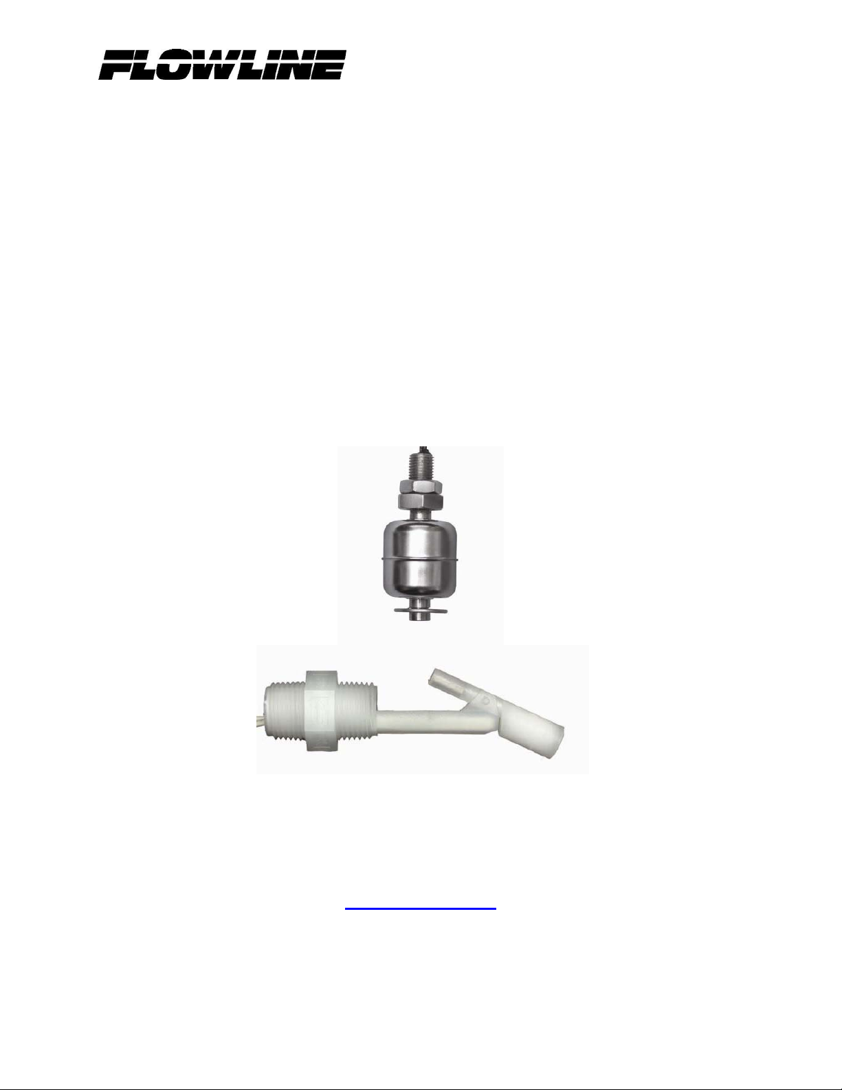
Switch-Tek
Horizontal and Vertical
And Float-Point
Float Switches
LV20, LV21, LV35, LV36, LH25,
LH29, LH35, AV_6 Series
22AUG 08
Rev A
Flowline, Inc.
10500 Humbolt Street
Los Alamitos, CA 90720
Tel: (562) 598-3015
Fax: (562) 431-8507
www.flowline.com
22 AUG 08 Switch-Tek Float Series 1 of 14
Rev A MN801839
Page 2

2 of 14 Switch-Tek Float Series 22 AUG 08
MN801839 Rev A
Page 3

Preface
This manual explains how to use the Switch-Tek series of horizontal and vertical floats.
Warranty, Service & Repair
To register your product with the manufacturer, go to the Flowline website for on-line
registration. The website address is as follows:
www.flowline.com
On-line Warranty Registration can be found under Contact Us in the Navigation Bar along the
side of the home page. If for some reason your product must be returned for factory service,
contact Flowline Inc. at (562) 598-3015 to receive a Material Return Authorization number
(MRA), providing the following information:
1. Part Number, Serial Number
2. Name and telephone number of someone who can answer technical questions
related to the product and its application.
3. Return Shipping Address
4. Brief Description of the Symptom
5. Brief Description of the Application
Once you have received a Material Return Authorization number, ship the product prepaid in its
original packing to:
Flowline Factory Service
MRA_____
10500 Humbolt Street
Los Alamitos, CA 90720
To avoid delays in processing your repair, write the MRA on the shipping label. Please include
the information about the malfunction with your product. This information enables our service
technicians to process your repair order as quickly as possible.
22 AUG 08 Switch-Tek Float Series 3 of 14
Rev A MN801839
Page 4

Warranty
Flowline warrants to the original purchaser of its products that such products will be free from
defects in material and workmanship under normal use and service for a period which is equal to
the shorter of one year from the date of purchase of such products or two years from the date of
manufacture of such products.
This warranty covers only those components of the products which hare non-moving and not
subject to normal wear. Moreover, products which are modified or altered, and electrical cables
which are cut to length during installation are not covered by this warranty.
Flowline’s obligation under this warranty is solely and exclusively limited to the repair or
replacement, at Flowline’s option, of the products (or components thereof) which Flowline’s
examination proves to its satisfaction to be defective. FLOWLINE SHALL HAVE NO
OBLIGATION FOR CONSEQUENTIAL DAMAGES TO PERSONAL OR REAL
PROPERTY, OR FOR INJURY TO ANY PERSON.
This warranty does not apply to products which have been subject to electrical or chemical
damage due to improper use, accident, negligence, abuse or misuse. Abuse shall be assumed
when indicated by electrical damage to relays, reed switches or other components. The warranty
does not apply to products which are damaged during shipment back to Flowline’s factory or
designated service center or are returned without the original casing on the products. Moreover,
this warranty becomes immediately null and void if anyone other than service personnel
authorized by Flowline attempts to repair the defective products.
Products which are thought to be defective must be shipped prepaid and insured to Flowline’s
factory or a designated service center (the identity and address of which will be provided upon
request) within 30 days of the discovery of the defect. Such defective products must be
accompanied by proof of the date of purchase.
Flowline further reserves the right to unilaterally waive this warranty and to dispose of any
product returned to Flowline where:
a. There is evidence of a potentially hazardous material present with product.
b. The product has remained unclaimed at Flowline for longer than 30 days after
dutifully requesting disposition of the product.
THERE ARE NO WARRANTIES WHICH EXTEND BEYONDTHE DESCRIPTION ON THE
FACE OF THIS WARRANTY. This warranty and the obligations and liabilities of Flowline
under it are exclusive and instead of, and the original purchaser hereby waives, all other
remedies, warranties, guarantees or liabilities, express or implied. EXCLUDED FROM THIS
WARRANTY IS THE IMPLIED WARRANTY OF FITNESS OF THE PRODUCTS FOR A
PARTICULAR PURPOSE OR USE AND THE IMPLIED WARRANTY OF
MERCHANTABILITY OF THE PRODUCTS.
This warranty may not be extended, altered or varied except by a written instrument signed by a
duly-authorized officer of Flowline, Inc.
4 of 14 Switch-Tek Float Series 22 AUG 08
MN801839 Rev A
Page 5

Table of Contents
Introduction ..........................................................................................................................6
Technology ..........................................................................................................................6
Installation............................................................................................................................7
Vertical Mounted Switches ......................................................................................7
Horizontal Mounted Switches ..................................................................................7
Environmental ......................................................................................................................8
Dimensions ..............................................................................................................8
Material Compatibility .............................................................................................9
Electrical interface .............................................................................................................10
Typical Current and Voltage Ratings ....................................................................10
AV_6 Series Float and Wire key ...........................................................................11
Specification ..........................................................................................................12
Maintenance .......................................................................................................................13
Cautions .................................................................................................................13
Testing the Installations .........................................................................................13
Cleaning Procedure ................................................................................................14
22 AUG 08 Switch-Tek Float Series 5 of 14
Rev A MN801839
Page 6

Introduction
1. Switches should be installed rigidly so the float or floats are free to move as the liquid
level changes.
2. Switches should be mounted in a tank area free of severe turbulence or protected from
such turbulence by appropriate and adequate slosh shields.
3. Vertical switch stems should be vertical for best results, but satisfactory operation is
possible in most liquids with the stem at up to a 30° angle from vertical.
4. Side mount switch stems must be mounted with the arrow vertically either up or down
depending on switch operation.
5. Care should be taken that switches are always operated within electrical ratings.
6. Orientation for standard Vertical switches can be changed from normally open to
normally closed dry or vice versa by removing the float and reversing it in the stem,
except with the LV20-2101, LV20-2201, LV21-1101 and LV21-1201.
Technology
Float switches consist of a float, magnet, reed switch and body/stem with mounting threads.
When the probe is dry, the float rests on the bottom of the stem such that the magnet does not
influence the reed switch. As the probe becomes immersed in liquid, the float becomes buoyant
and the magnet elevates causing the reed switch to change state.
6 of 14 Switch-Tek Float Series 22 AUG 08
MN801839 Rev A
Page 7

Installation
Operation is stated in the tank dry position.
• Vertical Mounted Switches:
o NC Operation:
SS Floats: Witness mark (round circle) down.
Plastic Floats: Magnets up.
o NO Operation:
SS Floats: Witness mark (round circle) up.
Plastic Floats: Magnets down.
*Note: LV20-2101, LV20-2201, LV21-1101 and LV21-1201 are not
reversible. The LV20-2101 and LV21-1101 are Normally Closed. The
LV20-2201 and LV21-1201 are Normally Open
• Horizontal Mounted Switches:
o NC Operation:
Arrow mounted vertically pointed down.
o NO Operation:
Arrow mounted vertically pointed up.
22 AUG 08 Switch-Tek Float Series 7 of 14
Rev A MN801839
Page 8

Environmental
Dimensions
LV35-S201 LV35-S401 LV36-S201
LV36-S401 LV36-S501 LV20-1501
LH35-S201 LH25-1201 LH25-1401
LV20-2101 & LV20-2201 LV21-1101 & LV21-1201
8 of 14 Switch-Tek Float Series 22 AUG 08
MN801839 Rev A
Page 9

Dimensions (continued)
LH29-1001 AV16-S243, AV26-S243,
AV36-S243, AV46-S243
and AV56-S243
AV26-S243 Shown
Material Compatibility:
o The LV36-S201, LV36-S401, LV35-S201, LV35-S401, LH35-S201 and LV36-S501 are
made of 316 stainless steel (316 SS) with 22 AWG, Teflon 24” wire.
o The LH25-1201, LH25-2401, LV21-1101, LV21-1201 and LV20-1501 are made of
Polypropylene (PP) with 22 AWG, Teflon 24” wire.
o The LV20-2101 and LV20-2201 are made of Polytetrafluoroethylene (PTFE) with 22
AWG, Teflon 24” wire.
o The LH29-1001 is made of Polypropylene (PP) with a Valox 420 stem and 22 AWG,
HALAR jacketed 120” wire.
o The AV16-S243, AV26-S243, AV36-S243, AV46-S243 and AV56-S243 are made of
316 Stainless Steel (316 SS) with a Polypropylene (PP) enclosure.
o Make sure that the switch is compatible with the application liquids. To determine the
chemical compatibility between the sensor and its application liquids, refer to the
Compass Corrosion Guide, available from Compass Publications (858-589-9636).
22 AUG 08 Switch-Tek Float Series 9 of 14
Rev A MN801839
Page 10

Electrical Interface
Typical Current and Voltage Ratings
• Note: The ratings at right are for resistive loads only. For inductive loads, maximum
switch life will be achieved if appropriate arc suppression is used.
• The following part numbers; LV36-S201, LV36-S401, LV35-S201, LV35-S401,
LV20-2101, LV20-2201, LV21-1101, LV21-1201, LH35-S201, LH25-1201, LH251401 and LH29-1001, are all two wire reed switch outputs where polarity does not
matter.
• Part numbers LV36-S501 and LV20-1501 are reed switch outputs with two additional
wires that are used to output the 100-ohm RTD used to measure the temperature of
the environment.
Watts Voltage Current Amps
15 240 AC
120 AC
100 DC
24 DC
30 240 AC
120 AC
100 DC
24 DC
60 240 AC
120 AC
100 DC
24 DC
100 240 AC
120 AC
100 DC
24 DC
-
0.12
0.10
0.30
0.14
0.28
0.07
0.28
0.40
0.50
0.20
0.50
0.40
1.00
0.40
1.00
10 of 14 Switch-Tek Float Series 22 AUG 08
MN801839 Rev A
Page 11

AV_6 Series Float and Wire Key
SPST
Switches
F-Dim
E-Dim
D-Dim
C-Dim
B-Dim
A-Dim
• Note: Each float will have a pair of colored wires for each level. For example, With
22 AUG 08 Switch-Tek Float Series 11 of 14
Rev A MN801839
AV16-S243
(1) Switch
RED
RED WHITE
RED WHITE BLUE
RED WHITE BLUE GREEN
BLACK BLACK BLACK BLACK BLACK
a AV56-S243, the B-Dim float will have two black wires as the switch contact.
AV26-S243
(2) Switches
AV36-S243
(4) Switches
Total Stem Length
AV46-S243
(4) Switches
AV56-S243
(5) Switches
Page 12

Specifications
Part
Number
Description Float
Mat’l
Stem
Mat’l
Max.
Oper.
Temp
Max
Pressure
(PSIG)
Float
SG
Nominal
VA
Fitting
(°C)
Standard Full-Size Vertical
LV36-S201
LV36-S401
LV35-S201
LV35-S401
LV20-2101
LV20-2201
LV21-1101
LV21-1201
Vertical small
Vertical small w/
slosh shield
Vertical large
Vertical large w/
slosh shield
Teflon, NC
Teflon, NO
Sub-minature, NC
Sub-minature, NO
316 SS
316 SS
316 SS
316 SS
PFTE
PFTE
PP
PP
316 SS
316 SS
316 SS
316 SS
PFTE
PTFE
PP
PP
200
200
200
200
150
150
105
105
500
500
300
300
25
25
50
50
0.70
0.70
0.70
0.70
0.69
0.69
0.85
0.85
100
100
30
30
60W
SPST
60W
SPST
15
15
¼” NPT
¼” NPT
1/8” NPT
1/8” NPT
1/8 – 27
NPT
1/8 – 27
NPT
3/8 –16
NPT
3/8 –16
NPT
Standard Horizontal
LH35-S201 Horizontal side
mount
LH25-1201
LH25-1401
Horz. side mount
Horz. side mount w/
slosh shield
316 SS 316 SS 200 500 0.60 30 ½” NPT
PP
PP
PP
PP
105
105
100
100
0.60
0.60
30
30
½” NPT
½” NPT
Vertical Floats with 100 Ohm RTD
LV36-S501 Vertical SS 316 SS 316 SS 200 500 0.70 100 ¼” NPT
LV20-1501 Vertical PP PP PP 105 100 0.85 30 1/8” NPT
Configured (Multi-Level) Vertical Assembly
AV16-S243
AV26-S243
AV36-S243
AV46-S243
AV56-S243
1-point float system
2-point float system
3-point float system
4-point float system
5-point float system
316 SS
316 SS
316 SS
316 SS
316 SS
316 SS
316 SS
316 SS
316 SS
316 SS
200
200
200
200
200
200
200
200
200
200
0.55
0.55
0.55
0.55
0.55
60
60
60
60
60
2” NPT
2” NPT
2” NPT
2” NPT
2” NPT
Interstitial Switch
LH29-1001 PP Valox
420
105 50 N/A 30W
SPST
N/A
Notes:
• Also applies to models with slosh shields
• The LV20-2101 and LV21-1101 are Normally Closed. The LV20-2201 and LV21-1201 are
Normally Open.
12 of 14 Switch-Tek Float Series 22 AUG 08
MN801839 Rev A
Page 13

Maintenance
Maintenance should consist of inspection to see that the float is free to move and not coated with
any substance, which would change its weight or volume significantly. If this occurs, the float
should be cleaned. This is easily accomplished without disturbing the installation. In addition,
the stem may be wiped down to remove any build-up. The only repair possible in the field is
replacement of either the float or stem. Dents or nicks on the float are usually of no consequence
to operation.
Cautions
FLOWLINE manufactures a wide range of liquid level switches and technologies. While each
of these switches are designed to operate in a wide variety of applications, it is the user's
responsibility to select a switch model that is appropriate for the application, install it properly,
perform tests of the installed system, and maintain all components. The failure to do so could
result in property damage or serious injury.
1. The pressure, temperature and electrical limitations shown for the specified level
switches must not be exceeded.
2. The pressures and temperatures must take into consideration possible surges in the
temperature and pressure of the system.
3. The liquids used must be compatible with the materials of construction. Specifications of
materials will be given upon request.
4. Life expectancy of the switch varies with applications. Contact the factory if life cycle
testing is required.
5. Ambient temperature changes can affect switch set points, since specific gravities of
liquids vary with temperature. Consult factory for assistance.
6. Level switches have been designed to be shock and vibration resistant. For maximum
life, both shock and vibration should be minimized. Consult factory for assistance.
7. Excessive contaminants in fluid may inhibit float operation, and occasional wipe down
may be necessary.
8. Level switches must not be field repaired
9. Physical damage to product may render product unserviceable.
10. Installation in a vessel made from magnetic materials may affect operation.
Testing the installation:
1. Power: Turn on power to the controller and/or power supply.
2. Immersing the switch: Immerse the sensing tip in its application liquid, by filling the
tank up to the switches point of actuation. An alternate method of immersing the switch
during preliminary testing is to hold a cup filled with application liquid up to the switch's
tip.
3. Test: With the switch being fluctuated between wet and dry states, the switch indicator
light in the controller should turn on and off. If the controller doesn't have an input
indicator, use a voltmeter or ammeter to ensure that the switch produces the correct
signal.
4. Point of actuation: Observe the point at which the rising or falling fluid level causes the
switch to change state, and adjust the installation of the switch if necessary.
22 AUG 08 Switch-Tek Float Series 13 of 14
Rev A MN801839
Page 14

Cleaning procedure:
1. Power: Make sure that all power to the switch, controller and/or power supply is
completely disconnected.
2. Switch removal: If necessary, make sure that the tank is drained well below the switch
prior to removal. Carefully, remove the sensor from the installation. Remove the outer
screen by pushing on the screen and turning is slightly to disconnect is from the bayonet
connector so that the float is exposed.
3. Cleaning the switch: Using a soft bristle brush and mild deter-gent, carefully wash the
switch. Do not use harsh abrasives such as steel wool or sandpaper, which might damage
the surface of the sensor. Do not use incompatible solvents, which may damage the
sensor's PP or PVDF plastic body. Take particular care to remove any scaling from the
float body and make sure that it moves freely.
4. Sensor installation: Follow the appropriate steps of installation as outlined in the
Installation section of this manual.
14 of 14 Switch-Tek Float Series 22 AUG 08
MN801839 Rev A
 Loading...