

Page 1
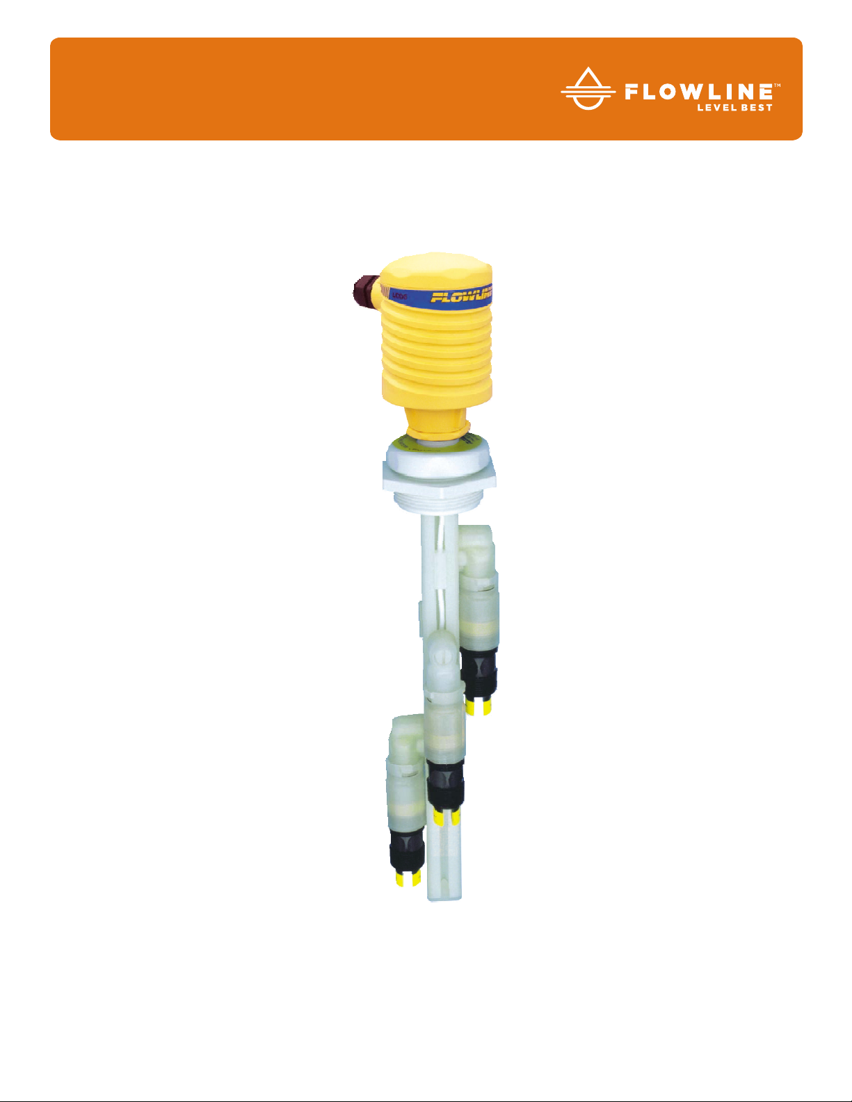
Smart Trak
w/ Compact Junction Box
™
AU18, AU28, AU38, AU48, AV16, AV26, AV36, AV46,
AZ18, AZ28, AZ38 & AZ48 Series
Owner’s Manual
Flowline, Inc. |. 10500 Humbolt Street, Los Alamitos, CA 90720. p 562.598.3015. f 562.431.8507. w flowline.com
MN301420 Rev A
Page 2
Specifications
Length: 8" to 10' (20 cm to 3m)
Switch points: 1 t 4 (field adjustable)
Orientation: ± 20˚ vertical
Process temp.: F: -40˚ to 1 7 6 ˚
C: -40˚ to 80˚
Pressure: Atmospheric
Wette d material: PP (20% glass fill)
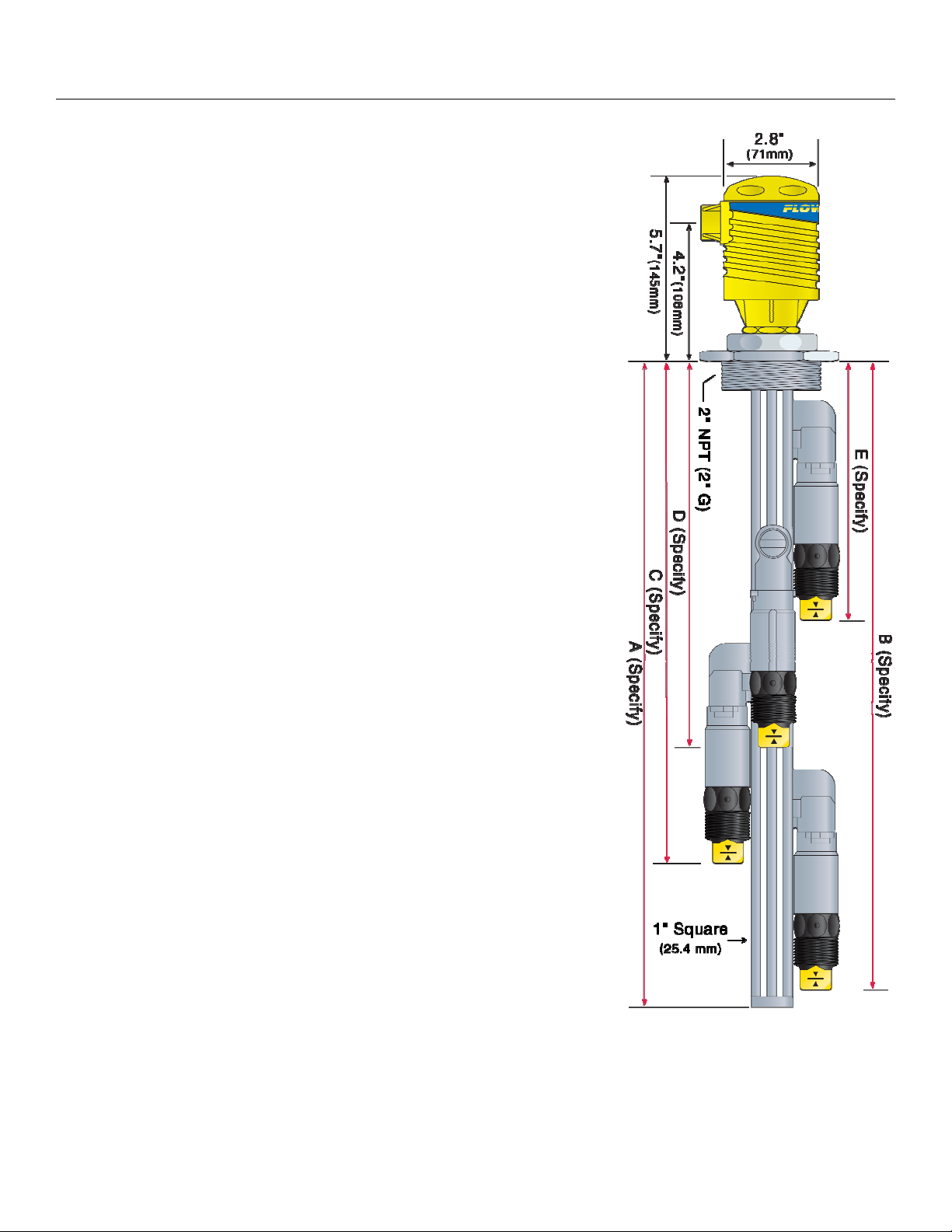
Process mount: 2" NPT (2" G)
Enclosure rating: NEMA 4X (IP65)
Installed height: 5.7" (14.4 cm) above tank process mount
Encl. material: PP , UL94VO
Conduit entrance: Single, 1/2" NPT
Termination: 12 poles
ULTRASONIC SENSOR
Supply voltage: 12-36 VDC
Consumption: 25 mA maximum
Contact type: (1) SPST relay
Contact rating: GP: 120 VAC/VDC @ 60 VA
IS: 32 VDC @ 0.5A
Cable type: 4-conductor / sensor, #22 AWG (shielded)
Contact output: Selectable NO/NC
Classification: Intrinsically safe
CE compliance: EN 50082-2 immunity
EN 55011 emission
EN 61010-1 safety
VIBRATION SENSOR
Step One
Supply voltage: 12-30 VDC
Consumption: 25 mA maximum
Contact type: (1) SPST relay
Contact rating: 120 VAC/VDC @ 60 VA
Cable type: 5-conductor / sensor, #24 AWG (shielded)
Contact output: Selectable NO/NC
Classification: General purpose
CE compliance: EN 50082-2 immunity
EN 55011 emission
EN 61010-1 safety
BUOYANCY SENSOR
Contact type: (1) SPDT reed
Contact rating: 120 VAC/VDC @ 15 VA
Cable type: 3-conductor / sensor, #22 AWG (shielded)
Contact output: Selectable NO/NC
Classification: General purpose
CE compliance: EN50082-2 immunity
EN 55011 emission
EN61010-1 safety
| 2
MN301420 rev A
Page 3
Components
V
V
A
A
A
V
V
A
A
A
Step Two
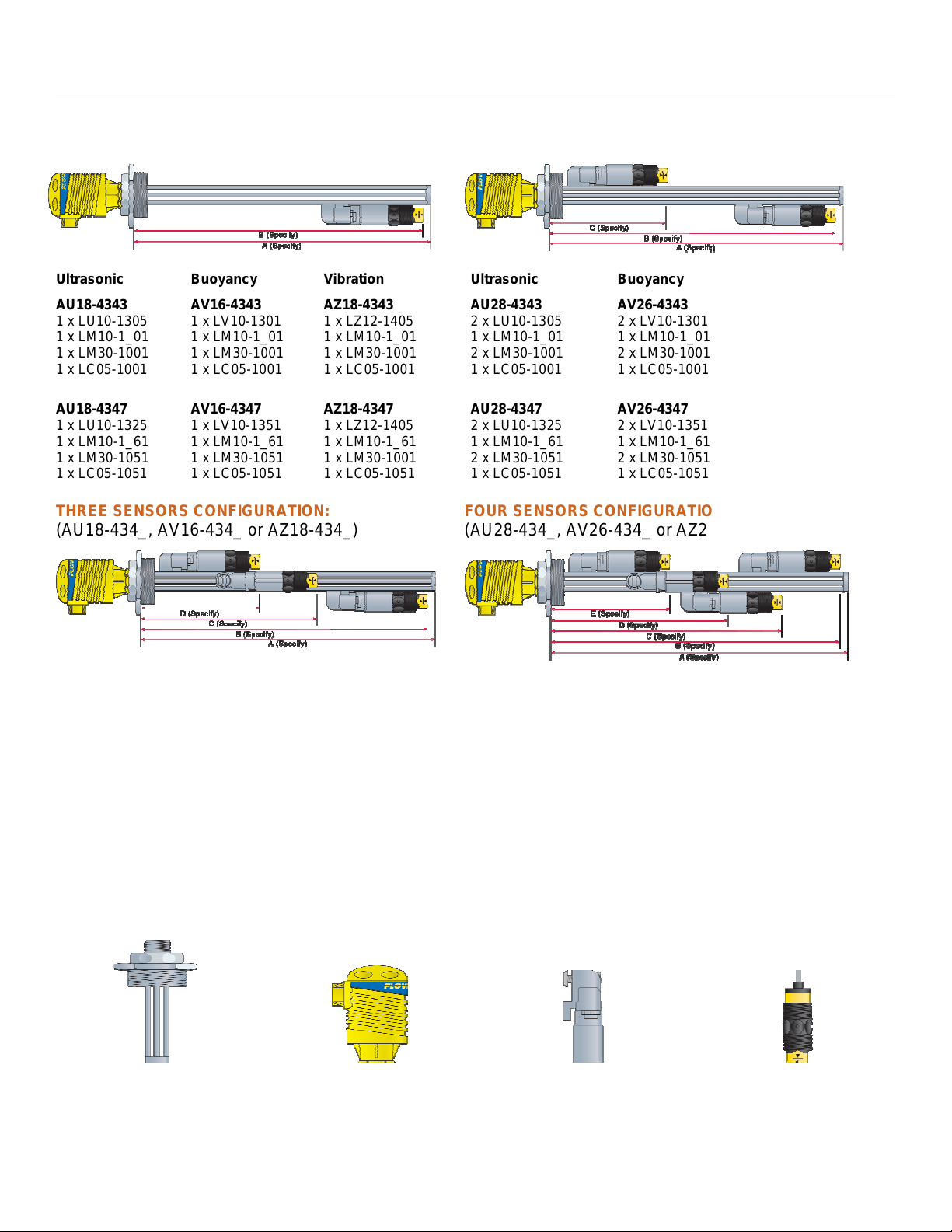
ONE SENSOR CONFIGURATION:
(AU18-434_, AV16-434_ or AZ18-434_)
Ultrasonic
AU18-4343
1 x LU10-1305
1 x LM10-1_01
1 x LM30-1001
1 x LC05-1001
AU18-4347
1 x LU10-1325
1 x LM10-1_61
1 x LM30-1051
1 x LC05-1051
Buoyancy
AV16-4343
1 x LV10-1301
1 x LM10-1_01
1 x LM30-1001
1 x LC05-1001
AV16-4347
1 x LV10-1351
1 x LM10-1_61
1 x LM30-1051
1 x LC05-1051
ibration
AZ18-4343
1 x LZ12-1405
1 x LM10-1_01
1 x LM30-1001
1 x LC05-1001
AZ18-4347
1 x LZ12-1405
1 x LM10-1_61
1 x LM30-1001
1 x LC05-1051
THREE SENSORS CONFIGURATION:
(AU18-434_, AV16-434_ or AZ18-434_)
TWO SENSORS CONFIGURATION:
(AU28-434_, AV26-434_ or AZ28-434_)
Ultrasonic
AU28-4343
2 x LU10-1305
1 x LM10-1_01
2 x LM30-1001
1 x LC05-1001
U28-4347
2 x LU10-1325
1 x LM10-1_61
2 x LM30-1051
1 x LC05-1051
FOUR SENSORS CONFIGURATION:
(AU28-434_, AV26-434_ or AZ28-434_)
Buoyancy
AV26-4343
2 x LV10-1301
1 x LM10-1_01
2 x LM30-1001
1 x LC05-1001
V26-4347
2 x LV10-1351
1 x LM10-1_61
2 x LM30-1051
1 x LC05-1051
ibration
AZ28-4343
2 x LZ12-1405
1 x LM10-1_01
2 x LM30-1001
1 x LC05-1001
Z28-4347
2 x LZ12-1405
1 x LM10-1_61
2 x LM30-1001
1 x LC05-1051
Ultrasonic
AU38-4343
3 x LU10-1305
1 x LM10-1_01
3 x LM30-1001
1 x LC05-1001
AU38-4347
3 x LU10-1325
1 x LM10-1_61
3 x LM30-1051
1 x LC05-1051
COMPONENT LIST:
Buoyancy
AV36-4343
3 x LV10-1301
1 x LM10-1_01
3 x LM30-1001
1 x LC05-1001
AV36-4347
3 x LV10-1351
1 x LM10-1_61
3 x LM30-1051
1 x LC05-1051
Smart Trak Fitting
P/N: LM10-1_01 or LM10-1_61
ibration
AZ38-4343
3 x LZ12-1405
1 x LM10-1_01
3 x LM30-1001
1 x LC05-1001
AZ38-4347
3 x LZ12-1405
1 x LM10-1_61
3 x LM30-1001
1 x LC05-1051
Compact Junction Box
P/N: LC05-1001 or LC05-1051
Ultrasonic
AU48-4343
4 x LU10-1305
1 x LM10-1_01
4 x LM30-1001
1 x LC05-1001
U48-4347
4 x LU10-1325
1 x LM10-1_61
4 x LM30-1051
1 x LC05-1051
Switch Car Kit
P/N: LM30-1001 or LM30-1051
Buoyancy
AV46-4343
4 x LV10-1301
1 x LM10-1_01
4 x LM30-1001
1 x LC05-1001
V46-4347
4 x LV10-1351
1 x LM10-1_61
4 x LM30-1051
1 x LC05-1051
ibration
AV48-4343
4 x LZ12-1405
1 x LM10-1_01
4 x LM30-1001
1 x LC05-1001
Z48-4347
4 x LZ12-1405
1 x LM10-1_61
4 x LM30-1001
1 x LC05-1051
Switch-Tek Level Switch
P/N: LU10-1305. LU10-1325,
LV10-1301, LV10-1351
or LZ12-1405
MN301420 rev A 3 |
Page 4

Safety Precautions Step Three
About this Manual: PLEASE READ THE ENTIRE MANUAL PRIOR TO INSTALLING OR USING THIS
PRODUCT. This manual includes information on the Smart Trak™ with Compact Junction Box: AU_5434_, AZ_8-434_ and AV_6-343_. The units are identical except for the number of switch points and the
sensors technology.
User's Responsibility for Safety: Flowline manufactures a wide range of liquid level sensors, controllers,
and mounting systems. It is the user's responsibility to select components that are appropriate for the
application, install them properly, perform tests of the installed system, and maintain all components. The
failure to do so could result in property damage or serious injury.
Proper Installation and Handling: Use a proper sealant with all installations. Never over tighten the
components. Always check for leaks prior to system start-up.
Material Compatibility:
o Glass filled Polypropylene (PP, a polyolefin): Track, end cap, wire retainer clips, bayonet
adapter, level switch and sensor car for all Smart Trak Assemblies.
o Polychlorotrifluoroethylene (PCTFE, a fluoroplastic): Sensor car locking bolt and screw.
o Polypropylene (PP, a polyolefin): Sensor, top compression fitting, thrust plate, locking pin and 2"
NPT fitting.
o Viton (a fluorocarbon): O-ring.
o Neoprene (w/silicon gel for lubrication): Wire gasket.
o Santoprene (w/silicon gel for lubrication): Seal plug.
Make sure that the application liquids are compatible with the materials that will be wetted. To determine
the chemical compatibility between the components and its application liquids, refer to the Compass
Corrosion Guide, available from Compass Publications.
Temperature and Pressure: Smart Trak™ is designed for use in application temperatures up to 80° C
(176° F). It is not designed for pressurized applications due to the wiring that must travel through a gasket
at the head.
Wiring and Electrical: Electrical wiring of any liquid level control system should be performed in
accordance with all applicable national, state, and local codes. Take care not to cut or break the outer
insulation jacket of wiring that may be immersed while routing cables in the Smart Trak™ system. Such
breaks of the liquid seal of the sensor system may lead to component failure.
Flammable, Explosive and Hazardous Applications: Smart Trak™ may be used within flammable or
explosive applications only if the associated components are rated intrinsically safe for such use. In
hazardous applications, use redundant measurement and control points, each having a different sensing
technology.
Make a Fail-Safe System: Design a fail-safe system that accommodates the possibility of transmitter or
power failure. In critical applications, Flowline recommends the use of redundant backup systems and
alarms in addition to the primary system.
| 4 MN301420 rev A
Page 5
Assembly of Smart Trak™
Step Four
About Smart Trak™: Flowline’s Smart Trak™ with Compact Junction Box Assembly is an adjustable
mounting system for installing multiple level sensors vertically within a tank. Mounted through a single point at
the top of the tank, up to 4 different sensors can be located at any depth on Smart Trak™. The compact
junction box features termination for the various wires from each level switch as well as a 1/2” conduit
connection. Smart Trak™ mounts vertically through a standard 2" NPT tank adapter, or on a side mount
bracket (such as the LM50-1001). Unlike prefabricated “trees” or pipes, Smart Trak™ allows you to experiment
with sensor position to account for variations in the point of actuation of each sensor during process testing.
Track: The track itself is approximately 1" square, and is from 8” to 10' long depending on the A-Dimension.
The track may be cut to length if desired. Four separate grooves run the length of the track, one on each side
of the square. These grooves hold the sensor cars that attach to Flowline sensors, and also serve to contain
the switch cable. The bottom of the track is capped with an end cap.
Level Switches: Smart Trak™ will include from 1 to 4 level switches used to identify
it’s own unique wet / dry
condition. The technologies used to indicate level are either
Ultrasonic, Buoyancy or Vibration. Each technology features a unique wiring/power
configuration (Ultrasonic and Vibration technologies require 12 to 36 VDC power for
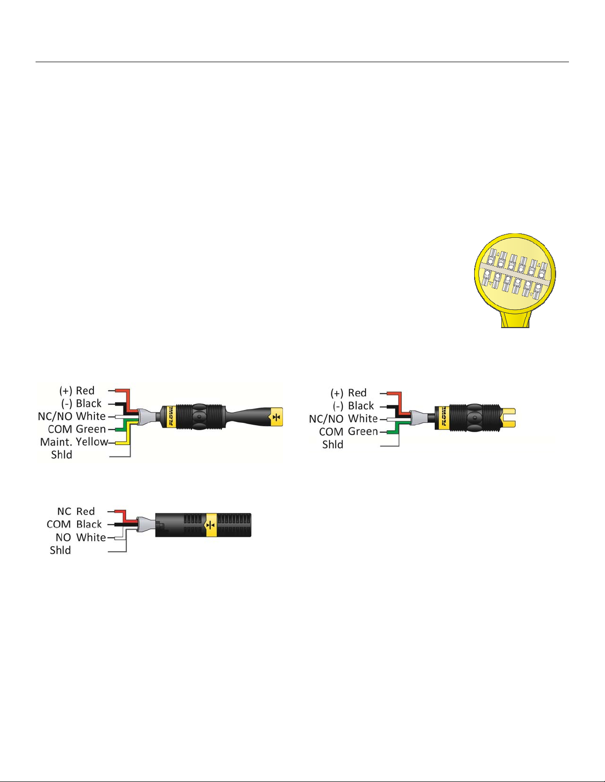
operation, see below). All of the switches are terminated in the Compact Junction Box.
The Compact Junction Box provides a 1/2” Conduit connection and 12 poles for wire
termination (for models AU45-434_ and AZ48-434_, common terminals such as
Positive (+) and Negative (-) power must be shared).
Compact Junction Box
(inside shown)
Vibration (LZ12-1405)
Wire Configuration
Ultrasonic (LU10-1305 or LU10-1325) Wire
Configuration
Buoyancy (LV10-1301 or LV10-1351)
Wire Configuration
MN301420 rev A 5 |
Page 6

Installation
SMART TRAK™, IN-TANK INSTALLATION
Step Five
Flowline's Smart Trak™ mounting system is an in-tank fitting, which enables users to install any technology,
along the entire length of track. Smart Trak™ may be installed thru the top wall of any tank or flange, using a
standard 2" NPT tank adapter or blind flange. If tank top is not available, Flowline's side mount bracket, LM501001, enables Smart Trak™ to be installed directly to the side wall or lip of the tank.
TANK ADAPTER:
FLANGE MOUNTING:
SIDE MOUNT BRACKET:
LIP OF TANK SIDE-WALL
| 6
MN301420 rev A
Page 7

Installation
Step Six
SMART TRAK™, INSTALLATION:
The Smart Trak™ with Compact Junction Box
assembly is designed to be installed through a
2” NPT (2” G) thread. The level switches will be
staggered through the fitting for installation.
A key feature of Smart Trak™ is the adjustability of
the level switches. When two level switches are
placed close together, one of the switches will
need to be moved to allow for the switches to be
staggered into the installation fitting. Once
installed, the level switch can be returned to its
required position.
MN301420 rev A 7 |
Page 8

Wiring
ULTRASONIC AND VIBRATION SWITCHES
Step Seven
(LU10-1305, LU10-1325, LZ12-1405):
The LU10-13_5 and LZ12-1405 switch can be wired normally open or normally closed for your application
requirement. Each switch requires 12 - 36 VDC power (12-30 VDC, LZ12) to operate the sensor and switch
the relay. The relay output can be wired as a dry contact. All illustrations below identify a Dry switch state as
the normal position of the relay.
SWITCHING A NORMALLY OPEN DC LOAD:
The Red wire connects to Positive (+) of the power supply and the Black wire connects to Negative (-). The
LOAD can be attached to either the Green or White wires. Complete the circuit by either connecting the Green
to (+) VDC power or White to (-) VDC power (see illustration below).
SWITCHING A NORMALLY CLOSED DC LOAD:
The Black wire connects to Positive (+) of the power supply and the Red wire connects to Negative (-). The
LOAD can be attached to either the Green or White wires. Complete the circuit by either connecting the Green
to (+) VDC power or White to (-) VDC power (see illustration below
MAINTENANCE ALARM (LZ12 VIBRATION ONLY):
For optimum performance and proactive maintenance, the sensor automatically adjusts for coating, and if
necessary, outputs a preventative maintenance alarm. The Yellow wire is a NPN transistor designed to switch
when a build-up of material prevents the vibration switch from operating at its operational frequency. Use the
Yellow wire to identify when the Vibration switch requires cleaning (see the LZ12 manual for wiring
information).
| 8
MN301420 rev A
Page 9

Wiring
BUOYANCY LEVEL SWITCH (LV10-1301 & LV10-1351):
The LV10-13_1 switch can be wired normally open or normally closed for your application requirement.
Step Eight
Normally Open:
Use the Black and White wires for operating the
LV10-_3_1 in a normally open state. Normally open
is defined as the switch being open when the float is
dry and closed when the float becomes submersed.
This operation is typical for indicating a high level.
Normally Closed:
Use the Black and Red wires for operating the
LV10-_3_1 in a normally closed state. Normally
closed is defined as the switch being closed when
the float is dry and open when the float becomes
submersed. This operation is typical for indicating a
low level.
MN301420 rev A 9 |
Page 10

Assembly of Smart Trak™ Step Nine
SMART TRAK™ ASSEMBLY DRAWING (SIDE VIEW)
Inventory:
One Smart Trak™ kit (LM10-1__1) includes the following parts:
1 Seal Plug 1 Top compression fitting
1 Wire gasket 1 Thrust Plate
1 Locking pin 1 2" NPT fitting
1 Track 1 End cap
SMART TRAK™ ASSEMBLY DRAWING (TOP VIEW):
SEAL PLUG ASSEMBLY DRAWING (SIDE VIEW)
| 10 MN301420 rev A
Page 11

Assembly of Switch Car™ Step Ten
SENSOR CAR AND BAYONET ADAPTER:
The sensor car assembly is the heart of the Smart Trak™ system. It slides in the grooves of the track, and
is locked into position by a plastic bolt and screw. The bayonet to 3/4" NPT adapter has a female 3/4"
NPT fitting on one end where the sensor (not included) will screw in, and a bayonet fitting on the other end
that attaches it onto the sensor car with a slight turn, with an O-ring in-between to provide tension for the
push-and-turn connection.
SWITCH CAR KIT ASSEMBLY DRAWING (SIDE VIEW)
INVENTORY:
One switch car kit (LM30-10_1) consists of the following parts:
1 Locking bolt 1 Locking Nut
1 Sensor car 1 O-ring
1 Bayonet to 3/4” NPT adapter
SWITCH CAR KIT TO SMART TRAK™
(Top View) (Side View)
DETERMINE THE PROPER WIRE LENGTH:
Don’t make the mistake of trimming the sensor wires too short before the process is tested. If the sensors
might need to be lowered in the future, leave sufficient slack in the wires to allow for future adjustment.
This extra wire may be stored in the bottom of the terminal strip housing, or elsewhere above the
compression fitting.
MN301420 rev A 11 |
Page 12

Maintenance Step Eleven
GENERAL:
The Smart Trak™ with Compact Junction Box requires no periodic maintenance except cleaning as required. It
is the responsibility of the user to determine the appropriate maintenance schedule, based on the specific
characteristics of the application liquids.
CLEANING PROCEDURE:
1. Power: Make Sure that all power to the sensor, controller and/or power supply is completely disconnected.
2. Sensor Removal: Make sure that the tank is in a state where it is safe to remove the sensors. Carefully,
remove the Smart Trak™ from the installation.
3. Cleaning the Sensor: Use a soft bristle brush and mild detergent, carefully wash the Smart Trak™. Do not
use harsh abrasives such as steel wool or sandpaper, which might damage the surface sensor. Do not use
incompatible solvents which may damage the sensor's PP or Ryton plastic body.
4. Sensor Installation: Follow the appropriate steps of installation as outlined in the installation section of
this manual.
TESTING THE INSTALLATION:
1. Power: Turn on power to the switches and/or power supply.
2. Immersing the switch: Immerse the sensing tip of each switch in its application liquid, by filling the tank
up to the switches point of actuation. An alternate method of immersing the switch during preliminary
testing is to hold a cup filled with application liquid up to the switch's tip.
3. Test: With the switch being fluctuated between wet and dry states, the switch will open or close depending
on wiring status. If the system doesn't have an input indicator, use a voltmeter or ammeter to ensure that
the switch produces the correct signal.
4. Point of actuation: Observe the point at which the rising or falling fluid level causes the switch to changes
state, and adjust the installation of the switch if necessary.
| 12 MN301420 rev A
Page 13

Maintenance
CURRENT TEST (ULTRASONIC AND VIBRATION ONLY):
Used to verify if the sensor is indicating a wet or dry condition. This test uses only two wires (Red and Black).
The sensor draws 5 mA (ultrasonic) or 8 mA (vibration) when it is dry, and 19 mA when wet. The White and
Green wires are not used.
Step Twelve
RELAY CONTACT TEST (ULTRASONIC AND VIBRATION ONLY):
Used to verify if the relay contact is switching between dry (open) and wet (closed). Test requires Red wired to
Positive (+) and Black wired to Negative (-) on a 12 to 36 VDC power supply. Check for continuity across
Green and White (open for dry and closed for wet). Reversing Red and Black wires will result in a closed when
dry and open when wet condition.
NORMALLY OPEN WIRING:
CONTACT TEST (BUOYANCY ONLY):
Used to verify if the reed switch is switching between dry (open) and wet (closed). Check for continuity across
Black and White (open for dry and closed for wet). Checking across Black and Red will result in a closed when
dry and open when wet condition.
MN301420 rev A 13 |
Page 14

Warranty, Returns and Limitations Step Thirteen
WARRANTY
Flowline warrants to the original purchaser of its products that such products will be free from defects in
material and workmanship under normal use and service in accordance with instructions furnished by Flowline
for a period of two years from the date of manufacture of such products. Flowline's obligation under this
warranty is solely and exclusively limited to the repair or replacement, at Flowline's option, of the products or
components, which Flowline's examination determines to its satisfaction to be defective in material or
workmanship within the warranty period. Flowline must be notified pursuant to the instructions below of any
claim under this warranty within thirty (30) days of any claimed lack of conformity of the product. Any product
repaired under this warranty will be warranted only for the remainder of the original warranty period. Any
product provided as a replacement under this warranty will be warranted for the full two years from the date of
manufacture.
RETURNS
Products cannot be returned to Flowline without Flowline's prior authorization. To return a product that is
thought to be defective, go to www.flowline.com, and submit a customer return (MRA) request form and follow
the instructions therein. All warranty and non-warranty product returns to Flowline must be shipped prepaid
and insured. Flowline will not be responsible for any products lost or damaged in shipment.
LIMITATIONS
This warranty does not apply to products which: 1) are beyond the warranty period or are products for which
the original purchaser does not follow the warranty procedures outlined above; 2) have been subjected to
electrical, mechanical or chemical damage due to improper, accidental or negligent use; 3) have been modified
or altered; 4) anyone other than service personnel authorized by Flowline have attempted to repair; 5) have
been involved in accidents or natural disasters; or 6) are damaged during return shipment to Flowline. Flowline
reserves the right to unilaterally waive this warranty and dispose of any product returned to Flowline where: 1)
there is evidence of a potentially hazardous material present with the product; or 2) the product has remained
unclaimed at Flowline for more than 30 days after Flowline has dutifully requested disposition. This warranty
contains the sole express warranty made by Flowline in connection with its products. ALL IMPLIED
WARRANTIES, INCLUDING WITHOUT LIMITATION, THE WARRANTIES OF MERCHANTABILITY AND
FITNESS FOR A PARTICULAR PURPOSE, ARE EXPRESSLY DISCLAIMED. The remedies of repair or
replacement as stated above are the exclusive remedies for the breach of this warranty. IN NO EVENT SHALL
FLOWLINE BE LIABLE FOR ANY INCIDENTAL OR CONSEQUENTIAL DAMAGES OF ANY KIND
INCLUDING PERSONAL OR REAL PROPERTY OR FOR INJURY TO ANY PERSON. THIS WARRANTY
CONSTITUTES THE FINAL, COMPLETE AND EXCLUSIVE STATEMENT OF WARRANTY TERMS AND NO
PERSON IS AUTHORIZED TO MAKE ANY OTHER WARRANTIES OR REPRESENTATIONS ON BEHALF
OF FLOWLINE. This warranty will be interpreted pursuant to the laws of the State of California. If any portion
of this warranty is held to be invalid or unenforceable for any reason, such finding will not invalidate any other
provision of this warranty.
For complete product documentation, video training, and technical support, go to www.flowline.com.
For phone support, call 562-598-3015 from 8am to 5pm PST, Mon - Fri.
(Please make sure you have the Part and Serial number available.)
| 14 MN301420 rev A
 Loading...