

Page 1
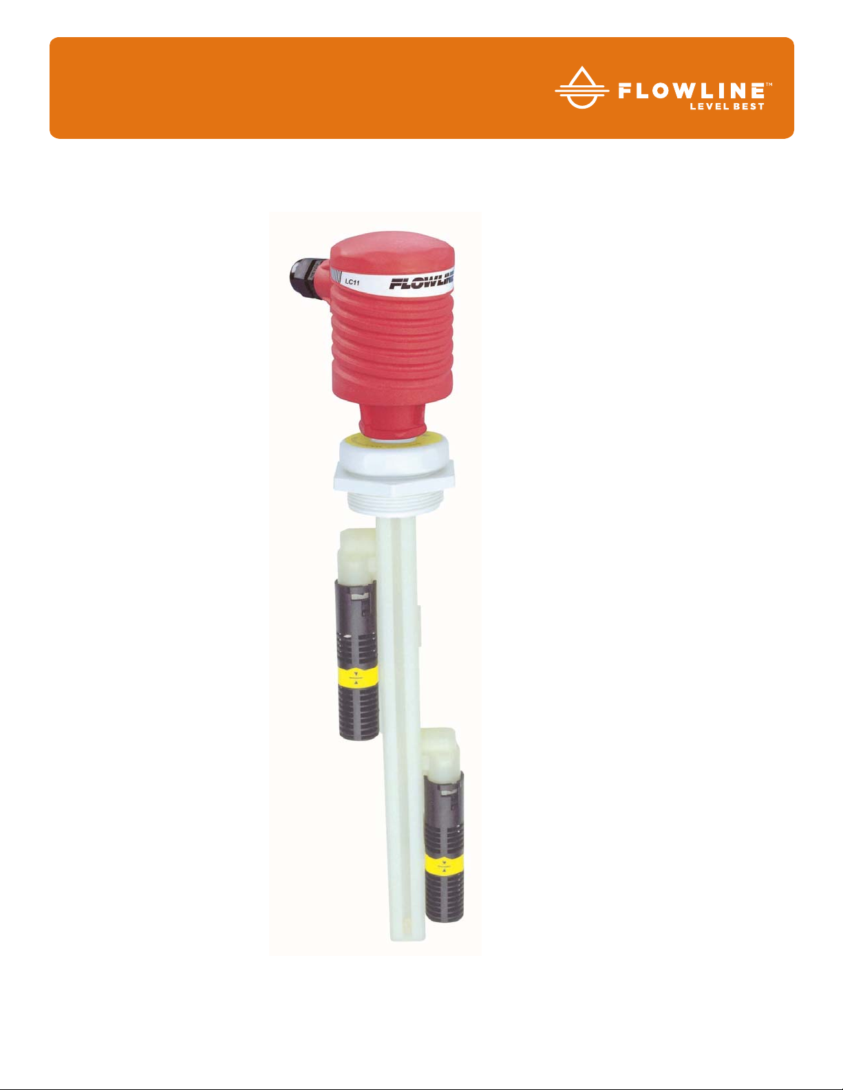
Smart -Trak™
With Compact Relay Controller
AU23, AV23, AZ23 Series Manual
Flowline, Inc. | 10500 Humbolt Street, Los Alamitos, CA 90720 p 562.598.3015 f 562.431.8507 w flowline.com MN301410 Rev A
Page 2

Introduction / Table of Contents Step One
The general purpose level switch package provides automatic tank filling and emptying up to 10’ (3m) between
two adjustable level switch points. The compact level controller with optional strobe alert provides one latching
16A relay for pump or valve control. Offered in three level sensor technologies, select the type based upon
your application media. This polypropylene liquid level switch package is widely selected for sump, process
and day tank level applications.
FEATURES
Fail-Safe relay control of pumps, valves or alarms with a 0 to 60 second delay.
Offered in three sensing technologies for broad application coverage: ultrasonic vibration & buoyancy.
Polypropylene enclosure rated NEMA 4X with swivel base for conduit alignment.
Easy setup with LED indicators for sensor(s), power and relay status.
Invert switch changes relay state from NO to NC without rewiring.
AC powered
TABLE OF CONTENTS
Specifications/Dimensions: ............................................................................................... 3
Parts Included: ...................................................................................................... 4
Configurations: ...................................................................................................... 5
Safety Precautions: ........................................................................................................... 6
Make a Fail-Safe System: ................................................................................................. 7
Getting Started: ................................................................................................................. 8
Features of Controller (Latch ON or Latch OFF): ................................................. 8
Guide to Controls: ................................................................................................. 7
Electrical: ........................................................................................................................ 10
VAC Power Input Wiring: .................................................................................... 10
Relay Input Wiring: .............................................................................................. 10
Strobe Alert Output: ............................................................................................ 10
Automatic Fill / Empty: ........................................................................................ 11
Changing from 120 to 240 VAC: ......................................................................... 12
Assembly of Smart Trak™: ............................................................................................. 13
Sensor Location: ................................................................................................. 14
Smart Trak™ Assembly: ..................................................................................... 15
Assembly of Switch Car: ................................................................................................. 16
Installation: ...................................................................................................................... 17
Maintenance: .................................................................................................................. 18
Controller Logic: .................................................................................................. 18
Troubleshooting .................................................................................................. 19
Warranty ......................................................................................................................... 20
| 2 MN30410 Rev A
Page 3
Specifications / Dimensions Step Two
Length: 8” (20cm) to 10’ (3m)
Switch points: 2 (field adjustable)
Orientation: ± 20° from vertical
Supply voltage: 120 / 240 VAC, 50 -
60 Hz.
Consumption: 0.25A maximum
Sensor supply: 13.5 VDC @ 27 mA
LED indication: Sensor, relay &
power status
Contact type: (1) SPDT Relay,
Latched
Contact rating: 250 VAC, 16A
Contact output: Selectable NO or NC
Contact delay: 0 to 60 seconds
Contact latch: Select On/Off
Process temp.: F: -40°to 176°
C: -40°to 80
Electronics temp.: F: -40°to 158°
C: -40°to 70°
Pressure: Atmospheric
Wetted material: PP (20% glass filled)
Enclosure rating: NEMA 4X (IP65)
Enclosure material: PP(U.L. 94 VO)
Process mount.: 2” NPT (2” G)
Enclosure rotation: 300°swivel base
Conduit entrance: Single, 1/2" NPT
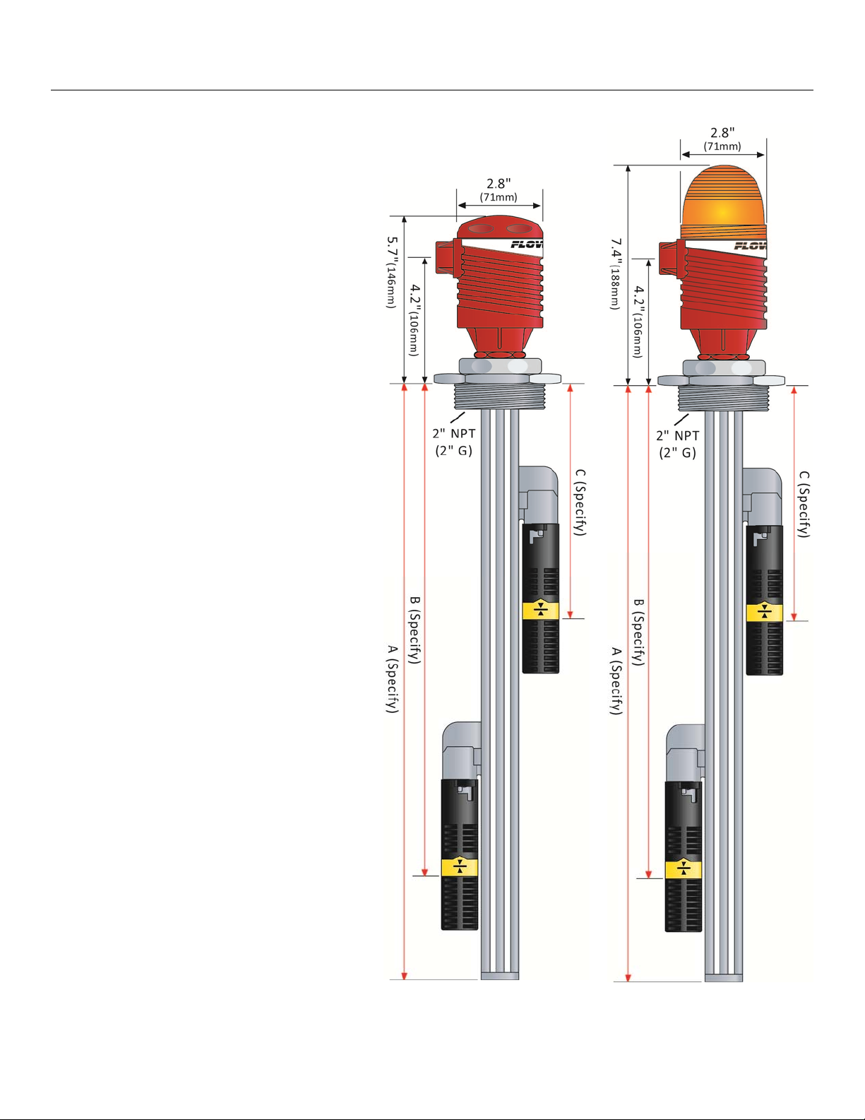
Installed height: 5.7” (14.4cm)”
7.4” (18.8cm) with
strobe
Classification: General purpose
Certificate number: LR 79326-3
CE compliance: EN 61326 EMC
EN 61010-1 Safety
Strobe Alert
Flash type: Xenon tube
Flash frequency: 1 per second
Strobe life: 10M cycles
Supply voltage: 120 VAC, 50-60 Hz.
Consumption: 3 Watts max.
Material: Polycarbonate
Enclosure rating: NEMA 4X (IP65)
Color: Amber
Without Strobe Alert
With Strobe Alert
MN301410 Rev A 3 |
Page 4

Specifications / Dimensions Step Two
Standard Faceplate
(Non-CE Versions)
CE Faceplate
(CE Versions)
Functional Diagram
PARTS INCLUDED:
240
Part Number
VAC
Option
AU23-4313
AU23-4317 G
AU23-4323
CE
Option
Add
(-CE)
N/A
Thread
NPT
NPT
Strobe
Alert
No
Yes
Description
Dual Level Switches
Ultrasonic (Gap Switch) Technology
AU23-4327 G
AV23-4313
AV23-4317 G No
AV23-4323
Add
(-E)
Add
(-CE)
NPT No
NPT Yes
Dual Level Switches
Buoyancy (Vertical Float) Technology
N/A
AV23-4327 G Yes
AZ23-4313
Az23-4317 G No
Add
(-CE)
AZ23-4323
NPT No
NPT Yes
Dual Level Switches
Vibration (Tuning Fork) Technology
N/A
AZ23-4327 G Yes
Owner’s Manual
| 4 LM900006 Rev 0_3
Page 5

Specifications / Dimensions Step Two
STANDARD CONFIGURATION:
(AU23-431_, AV23-431_ or AZ23-431_)
Ultrasonic Buoyancy Vibration
AU23-4313
2 x LU10-1305
1 x LM10-1_01
2 x LM30-1001
1 x LC11-1001
STANDARD CONFIGURATION:
AU23-4317
2 x LU10-1305
1 x LM10-1_61
2 x LM30-1001
1 x LC11-1051
AV23-4313
2 x LV10-1301
1 x LM10-1_01
2 x LM30-1001
1 x LC11-1001
AV23-4317
2 x LV10-1301
1 x LM10-1_61
2 x LM30-1001
1 x LC11-1051
AZ23-4313
2 x LZ12-1405
1 x LM10-1_01
2 x LM30-1001
1 x LC11-1001
(AU23-432_, AV23-432_ or AZ23-432_)
Ultrasonic Buoyancy Vibration
AU23-4323
2 x LU10-1305
1 x LM10-1_01
2 x LM30-1001
1 x LC11-1002
AU23-4327
2 x LU10-1305
1 x LM10-1_61
2 x LM30-1001
1 x LC11-1052
AV23-4323
2 x LV10-1301
1 x LM10-1_01
2 x LM30-1001
1 x LC11-1002
AV23-4327
2 x LV10-1301
1 x LM10-1_61
2 x LM30-1001
1 x LC11-1052
AZ23-4323
2 x LZ12-1405
1 x LM10-1_01
2 x LM30-1001
1 x LC11-1002
AZ23-4317
2 x LZ12-1405
1 x LM10-1_61
2 x LM30-1001
1 x LC11-1051
AZ23-4327
2 x LZ12-1405
1 x LM10-1_61
2 x LM30-1001
1 x LC11-1052
COMPONENT LIST:
Smart Trak™ Fitting P/N: Relay Controller P/N: Switch Car Kit P/N: Switch-Tek™ P/N:
LM10-1_01 or LM10-1_61 LC11-1001, LC11-1051,
LC11-1002 or LC11-1052
LM30-1001 LU10-1305, LV10-1301
or LZ12-1405
LM900006 Rev 0_3 5 |
Page 6
Safety Precautions Step Three
About This Manual: PLEASE READ THE ENTIRE MANUAL PRIOR TO INSTALLING OR USING THIS
PRODUCT. This manual includes information on the Smart Trak™ with Compact Relay Controller: AU2343__, AV23-43__ & AZ23-43__. The units are identical except for the sensor technology and optional
Strobe Alert.
User’s Responsibility for Safety: Flowline manufactures a wide range of liquid level sensors, controllers
and mounting systems. It is the user’s responsibility to select components that are appropriate for the
application, install them properly, perform tests of the installed system, and maintain all components. The
failure to do so could result in property damage or serious injury.
Proper Installation and Handling: Use a proper sealant with all installations. Never over tighten the
components. Always check for leaks prior to system start-up.
Material Compatibility:
o Glass filled Polypropylene (PP, a polyolefin): Track, end cap, wire retainer clips, bayonet adapter,
level switch and sensor car for all Smart Trak Assemblies.
o Polychlorotrifluoroethylene (PCTFE, a fluoroplastic): Sensor car locking bolt and screw.
o Polypropylene (PP, a polyolefin): Sensor, top compression fitting, thrust plate, locking pin and 2" NPT
fitting.
o Viton (a fluorocarbon): O-ring.
o Neoprene (w/silicon gel for lubrication): Wire gasket.
o Santoprene (w/silicon gel for lubrication): Seal plug.
Make sure that the application liquids are compatible with the materials that will be wetted. To determine
the chemical compatibility between the components and its application liquids, refer to the Compass
Corrosion Guide, available from Compass Publications.
Temperature and Pressure: Smart Trak™ is designed for use i n a p plic a t ion t e m perature s up to 8 0° C ( 176°
F). It is not designed for pressurized applicat ions due to the wiring tha t must travel thr ough a ga sket at the head .
Wiring and Electrical: Electrical wiring of any liquid level control system should be performed in
accordance with all applicable national, state, and local codes. Take care not to cut or break the outer
insulation jacket of wiring that may be immersed while routing cables in the Smart Trak™ system. Such
breaks of the liquid seal of the sensor system may lead to component failure.
Flammable, Explosive and Hazardous Applications: The AU23-43__, AZ23-43__ and AV23-34__
Smart Trak™ should not be used within classified hazardous environments.
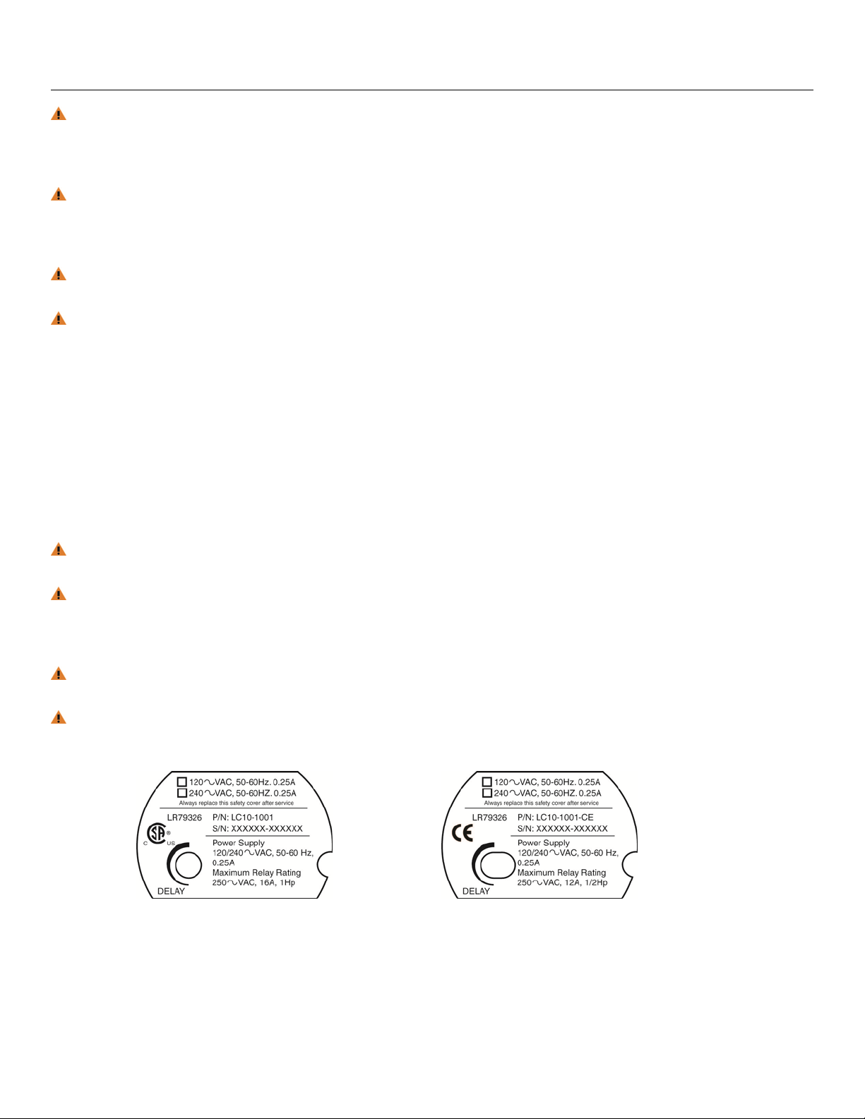
Safety Cover: Based upon the part number selected, a safety cover has been placed within the enclosure.
Always replace the safety cover after any service.
Standard Version (Non-CE)
CE Version
| 6 LM900006 Rev 0_3
Page 7

Safety Precautions Step Three
Make a Fail-Safe System: Design a fail-safe system that accommodates the possibility of relay or power
failure. If power is cut off to the controller, it will de-energize the relay. Make sure that the de-energized
state of the relay is the safe state in your process. For example, if controller power is lost, a pump filling a
tank will turn off if it is connected to the Normally Open side of the relay.
While the internal relay is reliable, over the course of time relay failure is possible in two modes: under a
heavy load the contacts may be “welded” or stuck into the energized position, or corrosion may buildup on
a contact so that it will not complete the circuit when it should. In critical applications, redundant backup
systems and alarms must be used in addition to the primary system. Such backup systems should use
different sensor technologies where possible.
While this manual offers some examples and suggestions to help explain the operation of FLOWLINE
products, such examples are for information only and are not intended as a complete guide to installing any
specific system.
Electrical Shock Hazard: It is possible to contact components on the controller that carry high voltage,
causing serious injury or death. All power to the controller and the relay circuit(s) it controls should be
turned OFF prior to working on the Smart Trak™. If it is necessary to make adjustments during powered
operation, use extreme caution and use only insulated tools. Making adjustments to powered controllers is
not recommended. Wiring should be performed by qualified personnel in accordance with all applicable
national, state and local electrical codes.
Install In a Dry Location: Although the sensors on
Smart Trak™ are designed to be submersed, the
controller housing is only liquid-resistant and made of
Polypropylene (PP). When installed properly, the
controller housing is not designed to be immersed. It
should be mounted in such a way that it does not
normally come into contact with fluid. Refer to an
industry reference to ensure that compounds that may
splash onto the controller housing will not damage it.
Such damage is not covered by the warranty.
Relay Contact Rating: The relay is rated for a 16 amp
resistive load. Many loads (such as a motor during startup or incandescent lights) are reactive and may have an
inrush current characteristic that may be 10 to 20 times
their steady-state load rating. The use of a contact
protection circuit may be necessary for your installation if
the 16 amp rating does not provide an ample margin for
such inrush currents.
LM900006 Rev 0_3 7 |
Page 8

Getting Started Step Five
FEATURES OF CONTROL (LATCH ON):
The Smart Trak™ with compact relay controller package is designed to receive signals from two liquid sensors.
It turns its internal relay ON or OFF (as set by the invert switch) in response to the presence of liquid on both
sensors, and changes the relay status back again when both sensors are dry.
Automatic Empty:
Latch is ON & Invert is OFF.
Relay will energize when level
reaches high switch (both
switches are wet). Relay will
de-energize when level is
below the bottom switch (both
switches are dry).
Automatic Empty:
Latch is ON & Invert is ON.
Relay will energize when level
is below the bottom switch
(both switches are dry). Relay
will de-energize when level
reaches high switch (both
switches are wet).
The relay is a single pole, double throw type; the controlled device can be connected to either the normally
open or normally closed side of the relay. A time delay from 0 to 60 seconds can be set (delay occurs on both
the make and break). Typical applications are automatic filling (starting fill pump at a low level and stopping
pump at a high level) or automatic emptying operations (opening a drain valve at a high level and closing valve
at low level).
FEATURES OF CONTROL (LATCH OFF):
With the latch OFF, the Smart Trak™ packa ge is d esigned to receive a signal from a sin gle liquid se nsor (t he
second sensor is ignored). It turns its internal r elay ON or OFF ( as set by the invert switch ) in response to the
presence of liquid, and changes the relay stat us back again w hen the sensor is dry.
High Alarm:
Invert is OFF. Relay will
energize when the switch
becomes Wet and will deenergize when the switch
becomes Dry (out of liquid).
Low Alarm:
Invert is ON. Relay will
energize when the switch
becomes Dry (out of liquid) and
will de-energize when the
switch becomes Wet.
Note: The package can only be used as a single high alarm or single low alarm and not
a as a high and low
alarm package because only one relay is present within the Smart Trak™. Also, the controller will only activate
upon the change of input 1A (1B will be ignored).
| 8 LM900006 Rev 0_3
Page 9

Getting Started (continued) Step Four
GUIDE TO CONTROLS:
Below is a listing and the location of the different components for the controller:
Standard Version (Non-CE)
1. Power indicator: This green LED lights when AC power is ON.
2. Relay indicator: This red LED will light whenever the controller energizes the relay, in response to the
proper condition at the sensor input(s) and after the time delay.
3. AC Power terminals: Connection of 120 VAC power to the controller. The setting may be changed to
240 VAC if desired. This requires changing internal jumpers; this is covered in the Installation section
of the manual. Polarity (neutral and hot) does not matter.
4. Relay terminals (NC, C, NO): Connect the device you wish to control (pump, alarm etc.) to these
terminals: supply to the COM terminal, and the device to the NO or NC terminal as required. The
switched device should be a non inductive load of not more than 16 amps; for reactive loads the current
must be derated or protection circuits used. When the red LED is ON and the relay is in the energized
state, the NO terminal will be closed and the NC terminal will be open.
5. Invert switch: This DIP switch reverses the logic of the relay control in response to the sensor(s):
conditions that used to energize the relay will make it turn off and vice versa.
6. Latch switch: This DIP switch determines how the relay will be energized in response to the two
sensor inputs. When LATCH is OFF, the relay responds to sensor Input 1A only; when LATCH is ON,
the relay will energize or de-energize only when both sensors (1Aand 1B) are in the same condition
(wet or dry). The relay will remain latched until both sensors change states.
7. Time Delay: After the input(s) change(s) state, this control sets a delay from 0.15 to 60 seconds
before the relay will respond.
8. Input 1Aand 1B indicator: These amber LEDs will light immediately whenever the appropriate sensor
attached to the terminals detects liquid, and will turn off when it is dry.
9. Input terminals: Connect the wiring from the sensors to these terminals: A to the upper pair, B (LC11
Series only) to the lower pair. Note the polarity: (+) is a 13.5 VDC, 27 mA power supply (to be
connected to the red wire of a Flowline sensor), and (-) is the return path from the sensor (to be
connected to the black wire of a Flowline sensor). If polarity is reversed, the sensors will not work.
CE Version (ex. AZ23-4223-CE)
LM900006 Rev 0_3 9 |
Page 10

Electrical Step Five
VAC POWER INPUT WIRING:
Observe the labeling on the controller. Note: Polarity does not matter with the AC input terminal.
WIRING:
The relay is a single pole, double throw type rated at 250 Volts AC, 16 Amps. The terminals Normally Open
(NO) and Normally Closed (NC) will be used in different applications. Remember that the "normal" state is
when the relay coil is de-energized and the Red relay LED is OFF (de-energized).
RELAY INPUT
A typical application for the Smart Trak™ with Compact Relay Controller is to operate a pump or valve
between the two set points (automatic fill or empty). In this application, a pump or valve can be wired to either
the Normally Open (NO) or Normally Closed (NC) side of the relay. In the example below, power to the Smart
Trak™ is not shown.
STROBE ALERT OUTPUT:
The Smart Trak™ features a latching controller primarily designed for automatic filling or emptying of a tank or
sump. If the Strobe Alert was added to your package, it can be wired to either indicate that the tank is
emptying or filling. Example, if a pump is wired to empty the tank, then wiring the strobe to the same terminal
(NO or NC) as the pump will have the light flash when the pump is active. Wiring to the opposite terminal as
the pump will have the light flash when the pump is not active. Note: The latching relay within the controller
prevents
the Strobe from switching when a high or level is reached.
| 10 LM900006 Rev 0_3
Page 11

Electrical (continued) Step Five
AUTOMATIC FILL:
This system consists of a tank with a high and low level sensor, and a pump or
valve that is operated by the controller. Proper fail-safe design for this system is to
stop filling if power is lost. Therefore, we connect the pump/valve to the NO side of
the relay. When energized, the device will activate and fill the tank. The relay LED
will correspond directly to the ON/OFF status of the pump/valve. NOTE: If the
pump motor load exceeds the rating of relay controller, a stepper relay of higher
capacity must be used as part of the system design.
Determining the settings of LATCH and INVERT: This is the way the system
must operate:
When both the high and low sensors are dry, the device should activate, starting to fill the tank.
When the low sensor gets wet, the device should stay ON.
When the high sensor gets wet, the device should turn OFF.
Latch: In any two-sensor control system, LATCH must be ON.
Invert: Referring to the logic chart in Step Nine, we look for the setting that will de-energize the relay (start the
pump) when both inputs are wet (Amber LEDs). In this system, Invert should be ON.
AUTOMATIC EMPTY:
Note that similar system logic can be used for an automatic empty operation simply
by controlling a pump/valve that takes fluid out of the tank instead of into it.
Connect the pump/valve to the NO side of the relay. When energized, the device
will activate and empty the tank.
Determining the settings of LATCH and INVERT: This is the way the system
must operate:
When both the high and low sensors are wet, the device should activate,
starting to empty the tank.
When the high sensor gets dry, the device should stay ON.
When the low sensor gets dry, the device should turn OFF.
Latch: In any two-sensor control system, LATCH must be ON.
Invert: Referring to the logic chart in Step Nine, we look for the setting that will de-energize the relay (start the
pump) when both inputs are wet (Amber LEDs). In this system, Invert should be OFF.
LM900006 Rev 0_3 11 |
Page 12

Electrical (continued) Step Five
CHANGING FROM 120 TO 240 VAC:
1. Remove the two screws from the top of the printed circuit board
(PCB) and gently slide the PCB from the housing. Use caution
when removing the PCB.
2. Located jumpers JWA, JWB and JWC on the PCB.
3. To change to 240 VAC, remove jumpers from JWB and JWC
and place a single jumper across JWA. To change to 120
VAC, remove jumper JWA and place jumpers across JWB and
JWC.
4. Gently return PCB into housing and replace the two screws.
RELAY LATCH LOGIC TABLE:
120 VAC 240 VAC
Configuration Configuration
With Latch ON, the relay will actuate when INPUT 1Aand INPUT 1B are in the same condition. The relay will
not change its condition until both inputs reverse their state.
Invert Off Latch ON
Input 1A Input 1B Relay
ON
OFF
ON
OFF
ON
ON
OFF
OFF
ON
No Change
No Change
OFF
Invert ON Latch ON
Input 1A Input 1B Relay
ON
OFF
ON
OFF
ON
ON
OFF
OFF
OFF
No Change
No Change
ON
The example shown below has the Invert Off and the Latch ON. With Invert ON, follow the above left chart.
Note: Some sensors (particularly buoyancy sensors) may have their own inverting capability (wired NO or
NC). This will change the logic of the invert switch. Check your system design.
With Latch OFF, the relay will
actuate only from INPUT 1A and
INPUT 1B will be ignored.
Invert Off Latch Off
Input 1A Input 1B Relay
ON
OFF
No Effect
No Effect
ON
OFF
Invert ON Latch Off
Input 1A Input 1B Relay
ON
OFF
No Effect
No Effect
OFF
ON
| 12 LM900006 Rev 0_3
Page 13

Assembly of Smart-Trak™ Step Six
ABOUT SMART TRAK™:
Flowline’s Smart Trak™ with Compact Relay Controller Assembly is an adjustable mounting system for
installing two level sensors vertically within a tank. Mounted through a single point at the top of the tank, both
sensors can be adjusted in the field. The compact relay controller features a 120/240 VAC latched controller
with a 250 VAC, 10A SPDT relay contract. Smart Trak™ mounts vertically through a standard 2" NPT tank
adapter or on a side mount bracket (such as the LM50-1001). Unlike prefabricated “trees” or pipes, Smart
Trak™ allows you to experiment with sensor position to account for variations in the point of actuation of each
sensor during process testing.
TRACK:
The track itself is approximately 1" square, and is from 8” to 10' long depending on
the A-Dimension. The track may be cut to length if desired. Four separate grooves
run the length of the track, one on each side of the square. These grooves hold
the sensor cars that attach to Flowline sensors, and also serve to contain the
switch cable. The bottom of the track is capped with an end cap.
RELAY CONTROLLER:
Both level switches are pre-wired before shipment to the 4-pole terminal strip
[Input 1A (+) & (-) & Input 1B (+) & (-)]. The switch technologies used to indicate
level are either Ultrasonic, Buoyancy or Vibration. The Compact Relay Controller
provides a 1/2” Conduit connection and 6 poles for wire termination of power and
relay contact. Use the AC, AC and GND terminals for providing power. Use the
NC, NC and COM terminals for interfacing to the relay contact.
Compact Relay Controller
(inside shown)
VIBRATION (LZ12-1405) WIRE CONFIGURATION:
Typically applied in wastewater media with light
coating and/or foaming characteristics. Use only
the Red and Black wires. White, Green and
Yellow wires are not used.
ULTRASONIC (LU10-1305) WIRE CO NFIGURATION:
Broadly applied in chemical, solvent, hydrocarbon
and light weight oil media. Use only the Red and
Black wires. White and Green wires are not used.
BUOYANCY (LV10-1301) WIRE CONFIGURATION:
Best applied in clean water or water-like chemical
media that is non-coating or scaling. Use the
White and Black wires for a Normally Open switch.
The Red and Black wires can be used for a
Normally Closed switch.
LM900006 Rev 0_3 13 |
Page 14

Assembly of Smart-Trak™ Step Six
SENSOR LOCATION:
Smart Trak™ is shipped with a specific length of the track and two sensors attached. The three values at the
end of the part number are assigned to provide the length of the track (A-Dimension), the activation location of
the bottom sensor (B-Dimension) and the activation location for the top sensor (C-Dimension). See example
below.
The sensors are attached to the track via a sensor car kit. The design of Smart
Trak™ enables the end user to adjust the location of the sensor in the field for
further fine tuning of the application. Simply loosen the locking nut on the sensor
to be moved, slide the sensor along the track and then turn the nut back to lock
into place.
NOTES:
No more than a ¼ to ½ a turn to unlock and lock the nut is required.
The cable for the sensor is designed to be submersed, is made of the same
material as the sensor.
Sensors can easily be raised from their original position, but may not be
lowered because of pre-cut cable lengths.
For systems ordered with both switches positioned at the bottom of the track
(A, B and C-dimensions are all the same), it does not matter which switch is
the high and which is the low. The controller logic looks for both switches to be
either WET or DRY before the relay switches. The switches can actually be
reversed and the system will still be functional.
If needed, the excess cable may be looped outside of the track with no effect
on the systems performance.
| 14 LM900006 Rev 0_3
Page 15

Assembly of Smart-Trak™ Step Six
Smart Trak™ Assembly Drawing (Side View) Inventory:
Inventory:
One Smart Trak™ kit (LM10-1__1)
includes the following parts:
1 x Seal Plug
1 x Top compression fitting
1 x Wire gasket
1 x Thrust Plate
1 x Locking pin
1 x 2" NPT fitting
1 x Track
1 x End cap
2 x Wire retainer clips (not shown)
Smart Trak™ Assembly Drawing (Top View):
Seal Plug Assembly Drawing (Side View):
LM900006 Rev 0_3 15 |
Page 16

Installation (continued) Step Seven
SENSOR CAR AND BAYONET ADAPTER:
The sensor car assembly is the heart of the Smart Trak™ system. It slides in the grooves of the track, and is
locked into position by a plastic bolt and screw. The bayonet to 3/4" NPT adapter has a female 3/4" NPT fitting
on one end where the sensor (not included) will screw in, and a bayonet fitting on the other end that attaches it
onto the sensor car with a slight turn, with an O-ring in-between to provide tension for the push-and-turn
connection.
Switch Car Kit Assembly Drawing (Side View)
Inventory:
One switch car kit (LM30-1001) consists of the
following parts:
1 x Locking bolt
1 x Locking Nut
1 x Sensor car
1 x O-ring
1 x Bayonet to 3/4” NPT adapter
Switch Car Kit to Smart Trak™ (Top View)
Switch Car Kit to Smart Trak™
(Side View)
DETERMINE THE PROPER WIRE LENGTH:
Don’t make the mistake of trimming the sensor wires too short before the process is tested. If the sensors
might need to be lowered in the future, leave sufficient slack in the wires to allow for future adjustment. This
extra wire may be stored in the bottom of the terminal strip housing, or elsewhere above the compression
fitting.
| 16 LM900006 Rev 0_3
Page 17

Installation Step Eight
SMART TRAK™, IN-TANK INSTALLATION:
Flowline's Smart Trak™ mounting system is an in-tank fitting, which enables users to install any technology,
along the entire length of track. Smart Trak™ may be installed thru the top wall of any tank or flange, using a
standard 2" NPT tank adapter or blind flange. If tank top is not available, Flowline's side mount bracket, LM501001, enables Smart Trak™ to be installed directly to the side wall or lip of the tank.
Tank Adapter: Flange Mounting: Side Mount Bracket (LM50 series):
Lip of Tank
Side-Wall
SMART TRAK™, INSTALLATION:
The Smart Trak™ with Compact Junction
Box assembly is designed to be installed
through a 2” NPT (2” G) thread. The level
switches will be staggered through the
fitting for installation.
A key feature of Smart Trak™ is the
adjustability of the level switches. When
two level switches are placed close
together, one of the switches will need to
be moved to allow for the switches to be
staggered into the installation fitting. Once
installed, the level switch can be returned
to its required position.
LM900006 Rev 0_3 17 |
Page 18

Maintenance Step Nine
GENERAL:
The Smart Trak™ with Compact Junction Box requires no periodic maintenance except cleaning as required.
It is the responsibility of the user to determine the appropriate maintenance schedule, based on the specific
characteristics of the application liquids.
CLEANING PROCEDURE:
1. Power: Make Sure that all power to the sensor, controller and/or power supply is completely
disconnected.
2. Sensor Removal: Make sure that the tank is in a state where it is safe to remove the sensors.
Carefully, remove the Smart Trak™ from the installation.
3. Cleaning the Sensor: Use a soft bristle brush and mild detergent, carefully wash the Smart Trak™.
Do not use harsh abrasives such as steel wool or sandpaper, which might damage the surface sensor.
Do not use incompatible solvents which may damage the sensor's PP or Ryton plastic body.
4. Sensor Installation: Follow the appropriate steps of installation as outlined in the installation section of
this manual.
CONTROLLER LOGIC:
1. Power LED: Make sure the Green power LED is On when power is supplied to the controller.
2. Input LED(s): The input LED(s) on the controller will be Amber when the switch(es) is/are wet and Off
when the switch(es) is/are dry. Note: see Step 5 regarding reed switches. If the LED's are not
switching the input LED, test the level switch.
3. Relays: When both inputs are wet (Amber LED's On), the relay will be energized (Red LED On). After
that, if one switch becomes dry, the relay will remain energized. Only when both switches are dry (both
amber LED's Off) will the controller de-energize the relay. The relay will not energize again until both
switches are wet. See the Relay Latch Logic Chart below for further explanation.
CURRENT TEST (ULTRASONIC
AND VIBRATION ONLY):
Using a Separate Power Supply Using Controller’s Power Supply
Used to verify if the sensor is
indicating a wet or dry condition.
This test uses only two wires (Red
and Black). The sensor draws 5
mA (ultrasonic) or 8 mA (vibration)
when it is dry, and 22 mA when
wet. The White and Green wires
are not used.
CONTACT TEST
(BUOYANCY ONLY):
Normally Open Switch
Used to verify if the reed switch is
switching between dry (open) and
wet (closed). Check for continuity
across Black and White (open for
dry and closed for wet). Checking
across Black and Red will result in
a closed when dry and open when
wet condition.
Normally Closed Switch
| 18 LM900006 Rev 0_3
Page 19

Maintenance Step Nine
TROUBLESHOOTING:
PROBLEM SOLUTION
Relay switches only from
one input.
Latch is turned OFF. Flip the latch switch to turn ON.
If Latch is ON, then check the input LEDs to make sure
they are switching ON and OFF as the level changes. If
the LEDs do not turn ON and OFF, the either the sensor
is not correctly wired or the sensor is not working.
Pump or Valve is
supposed to start, but it
does not.
First, check to make sure the input LEDs are both in the
same state (both ON or both OFF). If not, check wiring
to each sensor.
Second, check status of Relay LED. If incorrect, flip the
Invert switch to change the relay state.
Pump or Valve is
supposed to stop, but it
does not.
First, check to make sure the input LEDs are both in the
same state (both ON or both OFF). If not, check wiring
to each sensor.
Second, check status of Relay LED. If incorrect, flip the
Invert switch to change the relay state.
Controller is powered, but
nothing happens.
First check the Power LED to make sure it is Green. If
not, check the wiring, power and make sure the terminal
is seated correctly over the 6-pins.
LM900006 Rev 0_3 19 |
Page 20

Warranty, Returns and Limitations Step Ten
WARRANTY
Flowline warrants to the original purchaser of its products that such products will be free from defects in
material and workmanship under normal use and service in accordance with instructions furnished by Flowline
for a period of two years from the date of manufacture of such products. Flowline's obligation under this
warranty is solely and exclusively limited to the repair or replacement, at Flowline's option, of the products or
components, which Flowline's examination determines to its satisfaction to be defective in material or
workmanship within the warranty period. Flowline must be notified pursuant to the instructions below of any
claim under this warranty within thirty (30) days of any claimed lack of conformity of the product. Any product
repaired under this warranty will be warranted only for the remainder of the original warranty period. Any
product provided as a replacement under this warranty will be warranted for the full two years from the date of
manufacture.
RETURNS
Products cannot be returned to Flowline without Flowline's prior authorization. To return a product that is
thought to be defective, go to flowline.com, and submit a customer return (MRA) request form and follow the
instructions therein. All warranty and non-warranty product returns to Flowline must be shipped prepaid and
insured. Flowline will not be responsible for any products lost or damaged in shipment.
LIMITATIONS
This warranty does not apply to products which: 1) are beyond the warranty period or are products for which
the original purchaser does not follow the warranty procedures outlined above; 2) have been subjected to
electrical, mechanical or chemical damage due to improper, accidental or negligent use; 3) have been modified
or altered; 4) anyone other than service personnel authorized by Flowline have attempted to repair; 5) have
been involved in accidents or natural disasters; or 6) are damaged during return shipment to Flowline. Flowline
reserves the right to unilaterally waive this warranty and dispose of any product returned to Flowline where: 1)
there is evidence of a potentially hazardous material present with the product; or 2) the product has remained
unclaimed at Flowline for more than 30 days after Flowline has dutifully requested disposition. This warranty
contains the sole express warranty made by Flowline in connection with its products. ALL IMPLIED
WARRANTIES, INCLUDING WITHOUT LIMITATION, THE WARRANTIES OF MERCHANTABILITY AND
FITNESS FOR A PARTICULAR PURPOSE, ARE EXPRESSLY DISCLAIMED. The remedies of repair or
replacement as stated above are the exclusive remedies for the breach of this warranty. IN NO EVENT SHALL
FLOWLINE BE LIABLE FOR ANY INCIDENTAL OR CONSEQUENTIAL DAMAGES OF ANY KIND
INCLUDING PERSONAL OR REAL PROPERTY OR FOR INJURY TO ANY PERSON. THIS WARRANTY
CONSTITUTES THE FINAL, COMPLETE AND EXCLUSIVE STATEMENT OF WARRANTY TERMS AND NO
PERSON IS AUTHORIZED TO MAKE ANY OTHER WARRANTIES OR REPRESENTATIONS ON BEHALF
OF FLOWLINE. This warranty will be interpreted pursuant to the laws of the State of California. If any portion
of this warranty is held to be invalid or unenforceable for any reason, such finding will not invalidate any other
provision of this warranty.
For complete product documentation, video training, and technical support, go to flowline.com.
For phone support, call 562-598-3015 from 8am to 5pm PST, Mon - Fri.
(Please make sure you have the Part and Serial number available.)
| 20 LM900006 Rev 0_3
 Loading...